EP0974433A1 - Method and process for perforating a nonwoven web made of fibers or filaments - Google Patents
Method and process for perforating a nonwoven web made of fibers or filaments Download PDFInfo
- Publication number
- EP0974433A1 EP0974433A1 EP99490020A EP99490020A EP0974433A1 EP 0974433 A1 EP0974433 A1 EP 0974433A1 EP 99490020 A EP99490020 A EP 99490020A EP 99490020 A EP99490020 A EP 99490020A EP 0974433 A1 EP0974433 A1 EP 0974433A1
- Authority
- EP
- European Patent Office
- Prior art keywords
- fibers
- filaments
- cylinder
- orifice
- displacement
- Prior art date
- Legal status (The legal status is an assumption and is not a legal conclusion. Google has not performed a legal analysis and makes no representation as to the accuracy of the status listed.)
- Withdrawn
Links
Images


Classifications
-
- B—PERFORMING OPERATIONS; TRANSPORTING
- B32—LAYERED PRODUCTS
- B32B—LAYERED PRODUCTS, i.e. PRODUCTS BUILT-UP OF STRATA OF FLAT OR NON-FLAT, e.g. CELLULAR OR HONEYCOMB, FORM
- B32B38/00—Ancillary operations in connection with laminating processes
- B32B38/04—Punching, slitting or perforating
-
- A—HUMAN NECESSITIES
- A61—MEDICAL OR VETERINARY SCIENCE; HYGIENE
- A61F—FILTERS IMPLANTABLE INTO BLOOD VESSELS; PROSTHESES; DEVICES PROVIDING PATENCY TO, OR PREVENTING COLLAPSING OF, TUBULAR STRUCTURES OF THE BODY, e.g. STENTS; ORTHOPAEDIC, NURSING OR CONTRACEPTIVE DEVICES; FOMENTATION; TREATMENT OR PROTECTION OF EYES OR EARS; BANDAGES, DRESSINGS OR ABSORBENT PADS; FIRST-AID KITS
- A61F13/00—Bandages or dressings; Absorbent pads
- A61F13/15—Absorbent pads, e.g. sanitary towels, swabs or tampons for external or internal application to the body; Supporting or fastening means therefor; Tampon applicators
- A61F13/15577—Apparatus or processes for manufacturing
- A61F13/15707—Mechanical treatment, e.g. notching, twisting, compressing, shaping
- A61F13/15731—Treating webs, e.g. for giving them a fibrelike appearance, e.g. by embossing
-
- B—PERFORMING OPERATIONS; TRANSPORTING
- B26—HAND CUTTING TOOLS; CUTTING; SEVERING
- B26F—PERFORATING; PUNCHING; CUTTING-OUT; STAMPING-OUT; SEVERING BY MEANS OTHER THAN CUTTING
- B26F1/00—Perforating; Punching; Cutting-out; Stamping-out; Apparatus therefor
-
- D—TEXTILES; PAPER
- D04—BRAIDING; LACE-MAKING; KNITTING; TRIMMINGS; NON-WOVEN FABRICS
- D04H—MAKING TEXTILE FABRICS, e.g. FROM FIBRES OR FILAMENTARY MATERIAL; FABRICS MADE BY SUCH PROCESSES OR APPARATUS, e.g. FELTS, NON-WOVEN FABRICS; COTTON-WOOL; WADDING ; NON-WOVEN FABRICS FROM STAPLE FIBRES, FILAMENTS OR YARNS, BONDED WITH AT LEAST ONE WEB-LIKE MATERIAL DURING THEIR CONSOLIDATION
- D04H1/00—Non-woven fabrics formed wholly or mainly of staple fibres or like relatively short fibres
- D04H1/40—Non-woven fabrics formed wholly or mainly of staple fibres or like relatively short fibres from fleeces or layers composed of fibres without existing or potential cohesive properties
- D04H1/42—Non-woven fabrics formed wholly or mainly of staple fibres or like relatively short fibres from fleeces or layers composed of fibres without existing or potential cohesive properties characterised by the use of certain kinds of fibres insofar as this use has no preponderant influence on the consolidation of the fleece
- D04H1/4374—Non-woven fabrics formed wholly or mainly of staple fibres or like relatively short fibres from fleeces or layers composed of fibres without existing or potential cohesive properties characterised by the use of certain kinds of fibres insofar as this use has no preponderant influence on the consolidation of the fleece using different kinds of webs, e.g. by layering webs
-
- D—TEXTILES; PAPER
- D04—BRAIDING; LACE-MAKING; KNITTING; TRIMMINGS; NON-WOVEN FABRICS
- D04H—MAKING TEXTILE FABRICS, e.g. FROM FIBRES OR FILAMENTARY MATERIAL; FABRICS MADE BY SUCH PROCESSES OR APPARATUS, e.g. FELTS, NON-WOVEN FABRICS; COTTON-WOOL; WADDING ; NON-WOVEN FABRICS FROM STAPLE FIBRES, FILAMENTS OR YARNS, BONDED WITH AT LEAST ONE WEB-LIKE MATERIAL DURING THEIR CONSOLIDATION
- D04H13/00—Other non-woven fabrics
-
- B—PERFORMING OPERATIONS; TRANSPORTING
- B32—LAYERED PRODUCTS
- B32B—LAYERED PRODUCTS, i.e. PRODUCTS BUILT-UP OF STRATA OF FLAT OR NON-FLAT, e.g. CELLULAR OR HONEYCOMB, FORM
- B32B38/00—Ancillary operations in connection with laminating processes
- B32B38/04—Punching, slitting or perforating
- B32B2038/047—Perforating
-
- B—PERFORMING OPERATIONS; TRANSPORTING
- B32—LAYERED PRODUCTS
- B32B—LAYERED PRODUCTS, i.e. PRODUCTS BUILT-UP OF STRATA OF FLAT OR NON-FLAT, e.g. CELLULAR OR HONEYCOMB, FORM
- B32B2305/00—Condition, form or state of the layers or laminate
- B32B2305/10—Fibres of continuous length
- B32B2305/20—Fibres of continuous length in the form of a non-woven mat
Definitions
- the present invention relates to the field of tablecloths, nonwoven, made up of fibers or filaments, intended in particular but not exclusively to be used for the production of hygiene articles, for example for diapers for babies or for adult incontinence or protections feminine. They relate more particularly to a process and a device capable to produce perforations in such a nonwoven web.
- the document EP 0214608 describes a device and a process for making perforations through a nonwoven which, in a manner specific, is mainly composed of thermoplastic fibers.
- the device in question comprises two members between which the fiber web passes.
- the first member supports a plurality of studs while the other member includes recesses arranged in such a way that the ends of the studs penetrate into the tablecloth and repel certain fibers.
- the studs and the outline of the recesses of the second organ are heated so that the thermoplastic fibers that have been thus discarded are related to each other. Perforations are thus produced whose peripheral contours are consolidated, being formed of fibers bound together to each other.
- the process used in document EP 0214608 has the drawbacks on the one hand of requiring the use of thermoplastic fibers and on the other hand to provide, at the perforations, a some rigidity due to the presence, at the perforations, of the welded fibers to each other.
- the goal set by the applicant is to propose a method of perforation of a nonwoven web of fibers or filaments which overcomes the disadvantages cited above.
- each perforation is carried out, initially, by locally deforming the sheet so as to displace, in a direction substantially perpendicular to the general plane of said sheet, certain fibers, and, in a second step, to cut the fibers or filaments at the level of this deformation.
- the displacement of the fibers or filaments, towards the inside of the orifice is produced by suction.
- the cutting of the fibers or filaments in elevation relative to the other side of the part is made by moving a knife along this other side, while the fibers or filaments are locked in position at the orifice. If there is had no blockage in the position of the fibers or filaments, at the level of the orifice, it is it is probable that at least part of said fibers or filaments would be repelled towards inside the hole when the knife passes.
- this installation comprises a part provided with at least one through hole and a means of displacement of the fibers or filaments inside the orifice.
- this means of movement is constituted by the heating pad.
- the part is thin and the displacement means is capable of ensuring the displacement of the fibers or filaments to through the hole beyond the other side of the room; the installation also includes a means for cutting the fibers or filaments protruding from said other face.
- the thin piece is a rotating perforated cylinder and the means of displacement of the fibers or filaments is a suction system inside said cylinder.
- the nonwoven web of fibers or filaments is applied on the first external face of the rotating cylinder and, at the system level aspiration, the fibers or filaments penetrate, under the effect of the suction, inside the orifices formed in the cylinder until protruding beyond the other inner face of said cylinder.
- the cutting means is a fixed knife disposed inside the cylinder and the cutting blade of which comes at the other inner face of the cylinder.
- the installation according to the invention comprises at least one blocking block synchronized with the means of displacement to apply on the outer periphery of the orifice, after the displacement of the fibers or filaments towards the interior of the orifice.
- the stud does not penetrate properly speaking inside the orifice but has a configuration which is such that it just jam the fibers which delimit, at the level of the surface of the perforated cylinder, the base of the deformed area.
- each blocking stud is supported by a cylinder whose rotation is synchronized with the rotation of the suction perforated cylinder. This special effect has the effect, when of the application of the blocking pad on the fibers, to cause a slight displacement said fibers which promotes the action of the cutting blade.
- the perforated nonwoven tablecloth obtained by the process or using the device of the invention can be used in all areas where the presence of perforations is sought, and in particular in the field of articles hygiene, especially in contact with the user's skin, as a cover absorbent mattress.
- tablecloth can be used alone or in combination with other tablecloths.
- it will more particularly be a composite nonwoven, constituted superimposition and assembly, for example by thermobonding, of several tablecloths of which at least one will be a perforated nonwoven tablecloth according to the invention.
- the choice of constituent fibers or filaments of each tablecloth will be determined according to the desired application.
- a composite nonwoven may consist of two webs of card, one of which is perforated in accordance with the invention, the two sails being then assembled by thermobonding.
- a composite nonwoven can be formed by the assembly of two card webs between which is laid a sheet of filaments continuous perforated, of the Meltblown type.
- perforated nonwoven tablecloth is used alone or as a that constituting a composite nonwoven, it can, depending on the applications, be perforated only on a portion of its surface limited to what will be, during the manufacture of the final article, a liquid acquisition zone.
- the subject of the present invention is the production of perforations in a nonwoven web of fibers or filaments.
- the device 1 specially designed for the realization of such perforations consists of a first cylinder 2 which is a perforated cylinder suction, driven in rotation about its longitudinal axis 3, and a second cylinder 4, rotated about its longitudinal axis 5, parallel to the axis 3 of the first cylinder 2.
- the first cylinder 2 has, on its outer periphery, a part cylindrical, thin, provided with through holes 7. This part outer 6 is rotated in the direction of arrow F.
- This first cylinder 2 also has a cylindrical inner part 8, of the same axis longitudinal 3. This inner part 8 is fixed and delimits an internal chamber 9 to which is connected a suction source not shown.
- a suction chamber 10 which relates the internal chamber 9 and a determined angular portion 11 of the outer part 6.
- This suction chamber 10 is delimited on the one hand by two uprights 12, 13 fixed on the inner part 8 on either side of an opening 14 formed in said part 8 and on the other hand by a sealing lip 15 and a blade 16 extending respectively between each upright 12, 13 and the inner face 6 a of the outer part 6.
- the sealing lip 15 may in particular consist of a rubber band, the end 15 a of which is in contact with said inner face 6 a .
- the blade 16 is terminated by a cutting end forming a cutting blade 16 a , inclined towards the inside of the suction chamber 10. In the direction of rotation F of the first cylinder 2, the sealing lip 15 is disposed further upstream and the blade 16 further downstream.
- the suction source When the suction source is in operation, it creates a depression in the internal chamber 9 which causes a suction current to through the suction chamber 10, including through the orifices 7 of the part exterior 6 located at the angular portion 11 between the ends 15a and 16a of the sealing lip 15 and of the blade 16.
- the second cylinder 4 is provided, on its periphery, with blocking studs 17 which are arranged to cooperate with the orifices 7 made in the room outside 6 of the first cylinder 2.
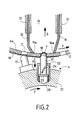
- each blocking pad 17 is in the form of a cylindrical element terminated by a hemispherical end 18 which is of a diameter slightly greater than the diameter of the orifice 7, with which it must cooperate.
- the two cylinders 2, 4 are synchronized so that during their respective rotation according to the arrows F, the hemispherical end 18 of a given stud 17 is applied precisely on the peripheral contour 7 a of the corresponding orifice 7, as this is clear from an examination of Figure 2.
- Perforations using the device 1 are carried out in the following conditions.
- the nonwoven web 19, consisting of fibers or filaments, for example from a card is applied to the first perforated cylinder 2 on a portion thereof delimited by two applicator rollers 20, driven in rotation at the same linear speed that the first perforated cylinder 2.
- the sheet of fibers 19 passes at the level of the angular portion 11 which is in relation to the suction chamber 10. Due to the intervening suction current through the orifices 7 located in this angular portion 11, the fibers or filaments which are located at the right of each orifice 7 tend to move towards the interior of the orifice 7 so that certain fibers or filaments are in elevation by relative to the inner face 6a of the outer part 6 of the first perforated cylinder 2.
- the hemispherical tip 18 is shaped such that when it bears on the periphery 7a of the orifice 7, it does not protrude beyond the inner face 6a of the part 6.
- it is preferably mounted on a spring 20 so as to compensate for any adjustment deviations and to avoid inadvertent crushing of the fibers or filaments.
- the function of the blocking pad 17 is to keep in position the fibers or filaments 21 displaced towards the inside of the orifice 7 so that the cutting blade 16 a can precisely cut the parts of fibers or filaments projecting, in the suction chamber 10, beyond the inner surface 6a of the part 6.
- the hemispherical end 18 of the pad 17 comes progressively close the orifice 7, the as of rotation two cylinders 2, 4 so that during the final blocking in position of the fibers or filaments and during cutting, the orifice 7 is completely closed.
- This progressive closure also makes it possible to limit the movement of the fibers or filaments towards the interior of the suction chamber 10 because there is already a partial pinching of certain fibers or filaments by the blocking pad 17 even before the passage of the orifice 7 in the suction chamber 10.
- the blocking block 17 is mounted in the outer part 21 of the second cylinder 4 via a housing 22 at bottom of which is disposed the spring 20.
- the stud 17 is arranged inside the housing 22 so that it turns on itself when it moves in the direction of the arrow H during the compression of the spring 20. More precisely, the stud 17 is provided with a pin 23, projecting inside the housing 22, this pin penetrating into a slide 23 formed in the wall of said housing 22 and which is inclined with respect to the direction H of displacement in height of the stud 17.
- the nonwoven web 19 is perforated continuously in the area where the second cylinder 4 cooperates with the orifices 7 of the first cylinder 2. It is understood that this zone can make all the width of the tablecloth or may be only part of this width depending on the application that is targeted. In particular when this ply 19 is used for the production of a hygiene article to promote the passage of liquid, it it may be wise to perforate said ply 19 only in the area which, in the made-up article, will correspond to the acquisition of liquid.
- the nonwoven web 19 which is perforated by the device 1 is a sheet composed of the superposition of three layers 25, 26, 27, the outer layers 25, 27 being two card webs coming from the two combers 28, 29 of a carder 30.
- the intermediate layer 26 is made of extruded blown filaments of the Meltblown type. So we get a composite sheet 19 'made up of the three said layers 25, 26, 27, the perforations of which are made by cutting the fibrous or filamentary elements from the three layers successive.
- hydrophilic or hydrophobic nature of the fibers or filaments constitutive of each layer is one of the parameters on which it is possible to intervene according to the desired applications.
- the displacement of the fibers or filaments, during aspiration, is all the easier as these fibers or filaments have a degree significant freedom in the starting layer (in one or more layers). It is therefore preferable than the mechanical or thermal means of entanglement or bonding of the fibers or filaments occurs after the perforations according to the invention.
- the perforated sheet 19 ′ then passes through a thermobonding assembly 31.
Abstract
Description
La présente invention concerne le domaine des nappes, non tissées, constituées de fibres ou de filaments, destinées notamment mais non exclusivement à être utilisées pour la réalisation d'articles d'hygiène, par exemple pour des couches-culottes pour bébés ou pour incontinents adultes ou encore des protections féminines. Elles concernent plus particulièrement un procédé et un dispositif aptes à produire des perforations dans une telle nappe non tissée.The present invention relates to the field of tablecloths, nonwoven, made up of fibers or filaments, intended in particular but not exclusively to be used for the production of hygiene articles, for example for diapers for babies or for adult incontinence or protections feminine. They relate more particularly to a process and a device capable to produce perforations in such a nonwoven web.
Le fait de former des perforations dans un matériau du type nappe non tissée voire film plastique est déjà connu pour favoriser par diffusion capillaire le passage de fluide à travers ledit matériau.The fact of forming perforations in a material of the non-ply type woven or even plastic film is already known to favor by capillary diffusion the passage of fluid through said material.
Plus particulièrement le document EP 0214608 décrit un dispositif et un procédé pour réaliser des perforations à travers un non tissé qui, de manière spécifique, est composé essentiellement de fibres thermoplastiques. Le dispositif en question comprend deux organes entre lesquels passe la nappe de fibres. Le premier organe supporte une pluralité de plots tandis que l'autre organe comprend des évidements disposés de telle sorte que les extrémités des plots pénètrent dans la nappe et repoussent certaines fibres. Les plots et le contour des évidements du second organe sont chauffés en sorte que les fibres thermoplastiques qui ont été ainsi écartées soient liées les unes aux autres. On réalise ainsi des perforations dont les contours périphériques sont consolidés, étant formés de fibres liées les unes aux autres.More particularly the document EP 0214608 describes a device and a process for making perforations through a nonwoven which, in a manner specific, is mainly composed of thermoplastic fibers. The device in question comprises two members between which the fiber web passes. The first member supports a plurality of studs while the other member includes recesses arranged in such a way that the ends of the studs penetrate into the tablecloth and repel certain fibers. The studs and the outline of the recesses of the second organ are heated so that the thermoplastic fibers that have been thus discarded are related to each other. Perforations are thus produced whose peripheral contours are consolidated, being formed of fibers bound together to each other.
Selon le demandeur, le procédé mis en oeuvre dans le document EP 0214608 présente comme inconvénients d'une part de nécessiter l'utilisation de fibres thermoplastiques et d'autre part d'apporter, au niveau des perforations, une certaine rigidité due à la présence, au niveau des perforations, des fibres soudées les unes aux autres.According to the applicant, the process used in document EP 0214608 has the drawbacks on the one hand of requiring the use of thermoplastic fibers and on the other hand to provide, at the perforations, a some rigidity due to the presence, at the perforations, of the welded fibers to each other.
Le but que s'est fixé le demandeur est de proposer un procédé de perforation d'une nappe non tissée de fibres ou de filaments qui pallie les inconvénients précités.The goal set by the applicant is to propose a method of perforation of a nonwoven web of fibers or filaments which overcomes the disadvantages cited above.
De manière caractéristique, selon l'invention, le procédé consiste à :
- amener la nappe non tissée en contact avec une première face d'une pièce de faible épaisseur pourvue d'au moins un orifice débouchant,
- déplacer vers l'intérieur de l'orifice les fibres ou filaments, constitutifs de la nappe, au droit dudit orifice, de sorte que certaines fibres ou filaments soient en élévation par rapport à l'autre face de la pièce,
- et couper lesdites fibres ou filaments en élévation.
- bringing the nonwoven web into contact with a first face of a thin piece provided with at least one through orifice,
- move the fibers or filaments constituting the sheet towards the inside of the orifice, in line with said orifice, so that certain fibers or filaments are in elevation relative to the other face of the part,
- and cutting said fibers or filaments in elevation.
Ainsi, selon le principe général de la présente invention, chaque perforation est réalisée, dans un premier temps, en déformant localement la nappe en sorte de déplacer, dans une direction sensiblement perpendiculaire au plan général de ladite nappe, certaines fibres, et, dans un second temps, à sectionner les fibres ou filaments au niveau de cette déformation.Thus, according to the general principle of the present invention, each perforation is carried out, initially, by locally deforming the sheet so as to displace, in a direction substantially perpendicular to the general plane of said sheet, certain fibers, and, in a second step, to cut the fibers or filaments at the level of this deformation.
Dans une variante préférée de réalisation, le déplacement des fibres ou filaments, vers l'intérieur de l'orifice, est réalisé par aspiration.In a preferred embodiment, the displacement of the fibers or filaments, towards the inside of the orifice, is produced by suction.
Avantageusement, la coupe des fibres ou filaments en élévation par rapport à l'autre face de la pièce se fait par déplacement d'un couteau selon cette autre face , alors que les fibres ou filaments sont bloqués en position au niveau de l'orifice. S'il n'y avait pas de blocage en position des fibres ou filaments, au niveau de l'orifice, il est vraisemblable qu'au moins une partie desdites fibres ou filaments serait repoussée vers l'intérieur de l'orifice lors du passage du couteau.Advantageously, the cutting of the fibers or filaments in elevation relative to the other side of the part is made by moving a knife along this other side, while the fibers or filaments are locked in position at the orifice. If there is had no blockage in the position of the fibers or filaments, at the level of the orifice, it is it is probable that at least part of said fibers or filaments would be repelled towards inside the hole when the knife passes.
C'est un autre objet de l'invention que de proposer une installation spécialement conçue pour réaliser la perforation d'une nappe non tissée de fibres ou de filaments, selon le procédé précité.It is another object of the invention to propose an installation specially designed for perforating a nonwoven web of fibers or filaments, according to the above method.
De manière connue par le document EP0214608, cette installation comprend une pièce pourvue d'au moins un orifice débouchant et un moyen de déplacement des fibres ou filaments à l'intérieur de l'orifice. Dans le document antérieur, ce moyen de déplacement est constitué par le plot chauffant.As is known from document EP0214608, this installation comprises a part provided with at least one through hole and a means of displacement of the fibers or filaments inside the orifice. In the document previous, this means of movement is constituted by the heating pad.
De manière caractéristique, selon l'invention, la pièce est de faible épaisseur et le moyen de déplacement est apte à assurer le déplacement des fibres ou filaments à travers l'orifice au-delà de l'autre face de la pièce ; de plus l'installation comprend un moyen de coupe des fibres ou filaments dépassant de ladite autre face.Typically, according to the invention, the part is thin and the displacement means is capable of ensuring the displacement of the fibers or filaments to through the hole beyond the other side of the room; the installation also includes a means for cutting the fibers or filaments protruding from said other face.
Dans une variante préférée de réalisation, la pièce de faible épaisseur est un cylindre perforé tournant et le moyen de déplacement des fibres ou filaments est un système d'aspiration intérieur audit cylindre.In a preferred embodiment, the thin piece is a rotating perforated cylinder and the means of displacement of the fibers or filaments is a suction system inside said cylinder.
Dans ces conditions, la nappe non tissée de fibres ou filaments est appliquée sur la première face, extérieure, du cylindre tournant et, au niveau du système d'aspiration, les fibres ou filaments pénètrent, sous l'effet de l'aspiration, à l'intérieur des orifices formés dans le cylindre jusqu'à dépasser au-delà de l'autre face, intérieure, dudit cylindre.Under these conditions, the nonwoven web of fibers or filaments is applied on the first external face of the rotating cylinder and, at the system level aspiration, the fibers or filaments penetrate, under the effect of the suction, inside the orifices formed in the cylinder until protruding beyond the other inner face of said cylinder.
De préférence le moyen de coupe est un couteau fixe disposé à l'intérieur du cylindre et dont la lame de coupe vient au niveau de l'autre face intérieure du cylindre.Preferably the cutting means is a fixed knife disposed inside the cylinder and the cutting blade of which comes at the other inner face of the cylinder.
Pour que la coupe des fibres ou filaments se fasse de manière nette sur toute la zone en élévation par rapport à la face intérieure du cylindre, il est nécessaire que lesdites fibres ou filaments soient bloqués en position au niveau de chaque orifice du cylindre perforé.So that the cutting of fibers or filaments is done neatly on any the area in elevation from the inside of the cylinder, it is necessary that said fibers or filaments are locked in position at each orifice of the perforated cylinder.
Pour obtenir ce blocage en position, de préférence l'installation selon l'invention comporte au moins un plot de blocage synchronisé avec les moyens de déplacement pour s'appliquer sur la périphérie extérieure de l'orifice, après le déplacement des fibres ou filaments vers l'intérieur de l'orifice. Le plot ne pénètre pas à proprement parler à l'intérieur de l'orifice mais a une configuration qui est telle qu'il vient coincer les fibres qui délimitent, au niveau de la surface du cylindre perforé, la base de la zone déformée. De préférence chaque plot de blocage est supporté par un cylindre dont la rotation est synchronisée avec la rotation du cylindre perforé aspirant. Cette disposition particulière a pour effet, lors de l'application du plot de blocage sur les fibres, d'entraíner un léger déplacement desdites fibres ce qui favorise l'action de la lame de coupe.To obtain this locking in position, preferably the installation according to the invention comprises at least one blocking block synchronized with the means of displacement to apply on the outer periphery of the orifice, after the displacement of the fibers or filaments towards the interior of the orifice. The stud does not penetrate properly speaking inside the orifice but has a configuration which is such that it just jam the fibers which delimit, at the level of the surface of the perforated cylinder, the base of the deformed area. Preferably each blocking stud is supported by a cylinder whose rotation is synchronized with the rotation of the suction perforated cylinder. This special effect has the effect, when of the application of the blocking pad on the fibers, to cause a slight displacement said fibers which promotes the action of the cutting blade.
La nappe non tissée perforée obtenue grâce au procédé ou à l'aide du dispositif de l'invention peut être utilisée dans tous les domaines où la présence de perforations est recherchée, et en particulier dans le domaine des articles d'hygiène, notamment en contact avec la peau de l'utilisateur, comme couverture du matelas absorbant.The perforated nonwoven tablecloth obtained by the process or using the device of the invention can be used in all areas where the presence of perforations is sought, and in particular in the field of articles hygiene, especially in contact with the user's skin, as a cover absorbent mattress.
Elle peut être utilisée seule ou en combinaison avec d'autres nappes. Dans ce dernier cas, il s'agira plus particulièrement d'un non tissé composite, constitué de la superposition et de l'assemblage, par exemple par thermoliage, de plusieurs nappes parmi lesquelles au moins une sera une nappe non tissée perforée conformément à l'invention. Bien sûr le choix des fibres ou filaments constitutifs de chaque nappe sera déterminé en fonction de l'application recherchée.It can be used alone or in combination with other tablecloths. In the latter case, it will more particularly be a composite nonwoven, constituted superimposition and assembly, for example by thermobonding, of several tablecloths of which at least one will be a perforated nonwoven tablecloth according to the invention. Of course the choice of constituent fibers or filaments of each tablecloth will be determined according to the desired application.
Par exemple un non tissé composite peut être constitué de deux voiles de carde, dont l'un est perforé conformément à l'invention, les deux voiles étant ensuite assemblés par thermoliage.For example, a composite nonwoven may consist of two webs of card, one of which is perforated in accordance with the invention, the two sails being then assembled by thermobonding.
Par exemple un non tissé composite peut être constitué par l'assemblage de deux voiles de carde entre lesquels est disposée une nappe de filaments continus perforée, du type Meltblown.For example, a composite nonwoven can be formed by the assembly of two card webs between which is laid a sheet of filaments continuous perforated, of the Meltblown type.
De plus, que la nappe non tissée perforée soit utilisée seule ou en tant que constituant d'un non tissé composite, elle peut, en fonction des applications, n'être perforée que sur une portion de sa surface limitée à ce qui sera, lors de la fabrication de l'article définitif, une zone d'acquisition de liquide.In addition, whether the perforated nonwoven tablecloth is used alone or as a that constituting a composite nonwoven, it can, depending on the applications, be perforated only on a portion of its surface limited to what will be, during the manufacture of the final article, a liquid acquisition zone.
La présente invention sera mieux comprise à la lecture de la description
qui va être faite d'un dispositif de perforation d'une nappe non tissée et d'exemples
d'utilisation d'une telle nappe, illustrée par le dessin annexé dans lequel :
La présente invention a pour objet la réalisation de perforations dans une nappe non tissée de fibres ou de filaments.The subject of the present invention is the production of perforations in a nonwoven web of fibers or filaments.
Le dispositif 1 spécialement conçu pour la réalisation de telles
perforations est constitué d'un premier cylindre 2 qui est un cylindre perforé
aspirant, entraíné en rotation autour de son axe longitudinal 3, et d'un second
cylindre 4, entraíné en rotation autour de son axe longitudinal 5, parallèle à l'axe
3 du premier cylindre 2.The device 1 specially designed for the realization of such
perforations consists of a
Le premier cylindre 2 comporte, sur sa périphérie extérieure, une pièce
cylindrique, de faible épaisseur, munie d'orifices débouchants 7. Cette pièce
extérieure 6 est entraínée en rotation dans le sens de la flèche F. Ce premier
cylindre 2 comporte également une pièce intérieure cylindrique 8, de même axe
longitudinal 3. Cette pièce intérieure 8 est fixe et délimite une chambre interne 9
à laquelle est raccordée une source d'aspiration non représentée.The
Entre la pièce extérieure 6 et la pièce intérieure 8 est constituée une
chambre d'aspiration 10 qui met en relation la chambre interne 9 et une portion
angulaire déterminée 11 de la pièce extérieure 6. Cette chambre d'aspiration 10 est
délimitée d'une part par deux montants 12, 13 fixés sur la pièce intérieure 8 de
part et d'autre d'une ouverture 14 pratiquée dans ladite pièce 8 et d'autre part par
une lèvre d'étanchéité 15 et une lame 16 s'étendant respectivement entre chaque
montant 12, 13 et la face intérieure 6a de la pièce extérieure 6. La lèvre
d'étanchéité 15 peut notamment être constituée d'une bande en caoutchouc dont
l'extrémité 15a est en contact avec ladite face intérieure 6a. La lame 16 est
terminée par une extrémité coupante formant une lame de coupe 16a, inclinée vers
l'intérieur de la chambre d'aspiration 10. Dans le sens de rotation F du premier
cylindre 2, la lèvre d'étanchéité 15 est disposée la plus en amont et la lame 16 la
plus en aval.Between the
Lorsque la source d'aspiration est en fonctionnement, il se crée une
dépression dans la chambre interne 9 qui provoque un courant d'aspiration à
travers la chambre d'aspiration 10, y compris à travers les orifices 7 de la pièce
extérieure 6 se trouvant au niveau de la portion angulaire 11 comprise entre les
extrémités 15a et 16a de la lèvre d'étanchéité 15 et de la lame 16.When the suction source is in operation, it creates a
depression in the
Le second cylindre 4 est muni, sur sa périphérie, de plots de blocage 17
qui sont agencés pour coopérer avec les orifices 7 pratiqués dans la pièce
extérieure 6 du premier cylindre 2.The
Plus précisément chaque plot de blocage 17 se présente sous la forme d'un
élément cylindrique terminé par un bout hémisphérique 18 qui est d'un diamètre
légèrement supérieur au diamètre de l'orifice 7, avec lequel il doit coopérer.More precisely, each
Les deux cylindres 2, 4 sont synchronisés en sorte que lors de leur
rotation respective selon les flèches F, le bout hémisphérique 18 d'un plot 17
donné vient s'appliquer précisément sur le contour périphérique 7a de l'orifice 7
correspondant, comme cela apparaít clairement à l'examen de la figure 2.The two
La réalisation de perforations à l'aide du dispositif 1 s'effectue dans les conditions suivantes.Perforations using the device 1 are carried out in the following conditions.
La nappe non tissée 19, constituée de fibres ou de filaments, provenant
par exemple d'une carde est appliquée sur le premier cylindre perforé 2 sur une
portion de celui-ci délimitée par deux rouleaux applicateurs 20, entraínés en
rotation à la même vitesse linéaire que le premier cylindre perforé 2. Lors de son
déplacement sur ledit cylindre perforé 2, la nappe de fibres 19 passe au niveau de
la portion angulaire 11 qui est en relation avec la chambre d'aspiration 10. Du fait
du courant d'aspiration intervenant à travers les orifices 7 localisés dans cette
portion angulaire 11, les fibres ou filaments qui se trouvent au droit de chaque
orifice 7 ont tendance à se déplacer vers l'intérieur de l'orifice 7 de sorte que
certaines fibres ou filaments sont en élévation par rapport à la face intérieure 6a
de la pièce extérieure 6 du premier cylindre perforé 2. Ce déplacement des fibres
ou filaments intervient dès que l'orifice 7, au droit desdites fibres ou filaments, est
passé au-delà de l'extrémité 15a de la lèvre d'étanchéité 15. Cette déformation des
fibres ou filaments est ensuite bloquée en position par application du bout
hémisphérique 18 du plot de blocage 17 venant coopérer avec l'orifice 7
correspondant. Les portions de fibres ou filaments, en élévation par rapport à la
face intérieure 6a de la pièce 6 sont enfin coupés par la lame de coupe 16a de la
lame 16, ce qui réalise la perforation recherchée. Les fibres ou filaments découpés
sont emmenés dans le courant d'aspiration G et évacués. La nappe non tissée
perforée 19' continue son déplacement sur le premier cylindre perforé 2.
Eventuellement, comme illustré à la figure 1, elle peut passer devant un autre
second cylindre 4' muni de plots de blocage s'il est souhaitable de pratiquer à
d'autres endroits ou selon d'autres tailles, d'autres perforations sur la nappe 19'.The
Concernant les plots de blocage 17, le bout hémisphérique 18 a une
configuration telle que, lorsqu'il est en appui sur le contour périphérique 7a de
l'orifice 7, il ne déborde pas au-delà de la face intérieure 6a de la pièce 6. De
plus, de préférence il est monté sur ressort 20 de manière à compenser les écarts
de réglage éventuels et éviter un écrasement intempestif des fibres ou filaments.
La fonction du plot de blocage 17 est de maintenir en position les fibres ou
filaments 21 déplacés vers l'intérieur de l'orifice 7 de telle sorte que la lame de
coupe 16a puisse couper précisément les parties de fibres ou filaments débordant,
dans la chambre d'aspiration 10, au-delà de la face intérieure 6a de la pièce 6. Il
est également à noter que le bout hémisphérique 18 du plot 17 vient obturer
progressivement l'orifice 7, au fur et à mesure de la rotation des deux cylindres 2,
4 de sorte que lors du blocage définitif en position des fibres ou filaments et lors
de la coupe, l'orifice 7 est totalement obturé. Cette obturation progressive permet
également de limiter le déplacement des fibres ou filaments vers l'intérieur de la
chambre d'aspiration 10 du fait qu'il existe déjà un pincement partiel de certaines
fibres ou filaments par le plot de blocage 17 avant même le passage de l'orifice
7 dans la chambre d'aspiration 10.On the locking
Dans une variante de réalisation, le plot 17 de blocage est monté dans la
pièce extérieure 21 du second cylindre 4 par l'intermédiaire d'un logement 22 au
fond duquel est disposé le ressort 20. Le plot 17 est agencé à l'intérieur du
logement 22 en sorte qu'il tourne sur lui-même lorsqu'il se déplace dans le sens
de la flèche H lors de la compression du ressort 20. Plus précisément le plot 17
est muni d'une goupille 23, en saillie à l'intérieur du logement 22, cette goupille
pénétrant dans une coulisse 23 formée dans la paroi dudit logement 22 et qui est
inclinée par rapport à la direction H de déplacement en hauteur du plot 17. Ainsi
lorsque le bout hémisphérique 18 du plot 17 vient s'appliquer sur la pièce
extérieure 6 lors de la rotation des deux cylindres 2, 4, cet embout hémisphérique
18 est repoussé dans la direction H du fait de la présence des fibres ou filaments
constitutifs de la nappe 19. Ce déplacement peut être plus ou moins important en
fonction de l'épaisseur de ladite nappe.In an alternative embodiment, the blocking
Lors de ce déplacement en hauteur du plot 17, la goupille 23 se déplace
corrélativement dans la coulisse 24. Du fait de l'inclinaison de cette coulisse 24,
le plot 17 effectue une légère rotation sur lui-même lors de son déplacement dans
la direction H. Cette légère rotation a pour effet de déplacer également les fibres
ou filaments les uns par rapport aux autres et d'obtenir une meilleure présentation
desdites fibres ou filaments lors de leur passage au niveau de la lame de coupe
16a.During this displacement in height of the
Dans l'exemple qui vient d'être décrit, la nappe non tissée 19 est perforée
de manière continue dans la zone où le second cylindre 4 vient coopérer avec les
orifices 7 du premier cylindre 2. On comprend que cette zone peut faire toute la
largeur de la nappe ou peut ne faire qu'une partie de cette largeur selon
l'application qui est visée. En particulier lorsque cette nappe 19 est mise en oeuvre
pour la réalisation d'un article d'hygiène pour favoriser le passage de liquide, il
peut être judicieux de ne perforer ladite nappe 19 que dans la zone qui, dans
l'article confectionné, correspondra à l'acquisition de liquide. In the example which has just been described, the
De même il est possible de ne pas réaliser de perforations en continu sur toute
la longueur de la nappe 19 mais de fractionner cette longueur en portions perforées et
en portions non perforées, par exemple en régulant en conséquence l'aspiration dans la
chambre interne 9 ou en éloignant légèrement l'un de l'autre les axes 3, 5 de rotation des
deux cylindres 2, 4.Similarly, it is possible not to make continuous perforations on any
the length of the
Dans l'exemple de réalisation qui est illustré à la figure 3, la nappe non tissée
19 qui est perforée grâce au dispositif 1 est une nappe composée de la superposition de
trois couches 25, 26, 27, les couches externes 25, 27 étant deux voiles de carde
provenant des deux peigneurs 28, 29 d'une carde 30. La couche 26 intermédiaire est
constituée de filaments extrudés soufflés du type Meltblown. Ainsi on obtient une
nappe composite 19' constituée des trois dites couches 25, 26, 27, dont les perforations
se font par la coupe des éléments fibreux ou filamentaires provenant des trois couches
successives.In the exemplary embodiment which is illustrated in FIG. 3, the
On comprend qu'il est possible de faire varier la disposition respective des
organes de l'installation illustrée à la figure 3 pour réaliser des perforations uniquement
sur l'une et/ou l'autre des trois couches précitées. Par exemple il serait envisageable de
détourner le parcours des voiles de carde constituant les couches extérieures 25, 27 de
manière à ce que seule la couche intermédiaire 26 du type Meltblown soit perforée.
Dans un exemple précis de réalisation, on a obtenu un non tissé composite à trois
couches 25, 26, 27 constituées respectivement de deux voiles de carde de 10 g/m2 pour
les couches externes 25, 27 et une nappe Meltblown de 3g/m2 pour la couche
intermédiaire 26.It will be understood that it is possible to vary the respective arrangement of the members of the installation illustrated in FIG. 3 in order to produce perforations only on one and / or the other of the three aforementioned layers. For example, it would be possible to divert the course of the card webs constituting the
Dans l'exemple illustré à la figure 3, il est question de la superposition de trois couches. Bien sûr il est possible de superposer uniquement deux couches voire plus de trois couches.In the example illustrated in Figure 3, we are talking about the superposition of three layers. Of course it is possible to superimpose only two layers or more three layers.
De plus le caractère hydrophile ou hydrophobe des fibres ou filaments constitutifs de chaque couche, voire de la nappe elle-même, est un des paramètres sur lesquels il est possible d'intervenir en fonction des applications recherchées.In addition, the hydrophilic or hydrophobic nature of the fibers or filaments constitutive of each layer, even of the tablecloth itself, is one of the parameters on which it is possible to intervene according to the desired applications.
Il est à souligner que le déplacement des fibres ou filaments, lors de
l'aspiration, est d'autant plus facile que ces fibres ou filaments ont un degré
important de liberté dans la nappe de départ (en une ou plusieurs couches). Il est
donc préférable que les moyens mécaniques ou thermiques d'entremêlement ou de
liaison des fibres ou filaments interviennent après qu'aient été réalisées les
perforations conformément à l'invention. Dans l'installation illustrée à la figure 3,
la nappe 19' perforée passe ensuite dans un ensemble 31 de thermoliage.It should be noted that the displacement of the fibers or filaments, during
aspiration, is all the easier as these fibers or filaments have a degree
significant freedom in the starting layer (in one or more layers). It is
therefore preferable than the mechanical or thermal means of entanglement or
bonding of the fibers or filaments occurs after the
perforations according to the invention. In the installation illustrated in Figure 3,
the
Claims (13)
Applications Claiming Priority (2)
| Application Number | Priority Date | Filing Date | Title |
|---|---|---|---|
| FR9809579A FR2781508B1 (en) | 1998-07-23 | 1998-07-23 | PROCESS AND DEVICE FOR PERFORATING A NONWOVEN FABRIC OF FIBERS OR FILAMENTS |
| FR9809579 | 1998-07-23 |
Publications (1)
| Publication Number | Publication Date |
|---|---|
| EP0974433A1 true EP0974433A1 (en) | 2000-01-26 |
Family
ID=9529054
Family Applications (1)
| Application Number | Title | Priority Date | Filing Date |
|---|---|---|---|
| EP99490020A Withdrawn EP0974433A1 (en) | 1998-07-23 | 1999-07-16 | Method and process for perforating a nonwoven web made of fibers or filaments |
Country Status (3)
| Country | Link |
|---|---|
| EP (1) | EP0974433A1 (en) |
| JP (1) | JP2000096412A (en) |
| FR (1) | FR2781508B1 (en) |
Cited By (14)
| Publication number | Priority date | Publication date | Assignee | Title |
|---|---|---|---|---|
| EP1172188A1 (en) * | 2000-07-12 | 2002-01-16 | Albis | Method and apparatus for perforationg non-woven webs |
| FR2811604A1 (en) * | 2000-07-12 | 2002-01-18 | Albis | Non-woven sheet material perforating procedure and machine uses cylinder with sharp-edged hollow inserts and roller with perforating fingers |
| FR2811603A1 (en) * | 2000-07-12 | 2002-01-18 | Albis | Non-woven sheet material perforating procedure and machine uses cylinder with sharp-edged hollow inserts and roller with perforating fingers |
| US20110309544A1 (en) * | 2010-06-21 | 2011-12-22 | Matthew Todd Hupp | Method for providing a web with unique perforations |
| US8268429B2 (en) | 2010-06-21 | 2012-09-18 | The Procter & Gamble Company | Perforated web product |
| US8283013B2 (en) | 2010-06-21 | 2012-10-09 | The Procter & Gamble Company | Uniquely perforated web product |
| US8287976B2 (en) | 2010-06-21 | 2012-10-16 | The Procter & Gamble Company | Uniquely perforated web product |
| US8287977B2 (en) | 2010-06-21 | 2012-10-16 | The Procter & Gamble Company | Uniquely perforated web product |
| US8443725B2 (en) | 2010-06-21 | 2013-05-21 | The Procter & Gamble Company | Method of perforating a web |
| US8468938B2 (en) | 2010-06-21 | 2013-06-25 | The Procter & Gamble Company | Apparatus for perforating a web material |
| US8535483B2 (en) | 2010-06-21 | 2013-09-17 | The Procter & Gamble Company | Apparatus for uniquely perforating a web material |
| US8757058B2 (en) | 2010-06-21 | 2014-06-24 | The Procter & Gamble Company | Process for perforating a web |
| US8763523B2 (en) | 2010-06-21 | 2014-07-01 | The Procter & Gamble Company | Method of perforating a web material |
| US8763526B2 (en) | 2010-06-21 | 2014-07-01 | The Procter & Gamble Company | Apparatus for perforating a web material |
Citations (5)
| Publication number | Priority date | Publication date | Assignee | Title |
|---|---|---|---|---|
| US4636417A (en) * | 1974-12-10 | 1987-01-13 | Rasmussen O B | Fibrous reticular sheet material |
| EP0214608A2 (en) * | 1985-09-09 | 1987-03-18 | Kimberly-Clark Corporation | Apertured nonwoven web |
| EP0598970A1 (en) * | 1992-11-17 | 1994-06-01 | PANTEX S.r.l. | Method and apparatus for manufacturing a product in membrane or film for covering sanitary towels or nappies or for filtering systems, and such like |
| FR2704179A1 (en) * | 1993-04-19 | 1994-10-28 | Guial Sa | Composite planar material comprising perforated film and thermoplastic fibers, use and method of manufacture |
| US5573719A (en) * | 1994-11-30 | 1996-11-12 | Kimberly-Clark Corporation | Process of making highly absorbent nonwoven fabric |
-
1998
- 1998-07-23 FR FR9809579A patent/FR2781508B1/en not_active Expired - Fee Related
-
1999
- 1999-07-16 EP EP99490020A patent/EP0974433A1/en not_active Withdrawn
- 1999-07-19 JP JP11204588A patent/JP2000096412A/en active Pending
Patent Citations (5)
| Publication number | Priority date | Publication date | Assignee | Title |
|---|---|---|---|---|
| US4636417A (en) * | 1974-12-10 | 1987-01-13 | Rasmussen O B | Fibrous reticular sheet material |
| EP0214608A2 (en) * | 1985-09-09 | 1987-03-18 | Kimberly-Clark Corporation | Apertured nonwoven web |
| EP0598970A1 (en) * | 1992-11-17 | 1994-06-01 | PANTEX S.r.l. | Method and apparatus for manufacturing a product in membrane or film for covering sanitary towels or nappies or for filtering systems, and such like |
| FR2704179A1 (en) * | 1993-04-19 | 1994-10-28 | Guial Sa | Composite planar material comprising perforated film and thermoplastic fibers, use and method of manufacture |
| US5573719A (en) * | 1994-11-30 | 1996-11-12 | Kimberly-Clark Corporation | Process of making highly absorbent nonwoven fabric |
Cited By (16)
| Publication number | Priority date | Publication date | Assignee | Title |
|---|---|---|---|---|
| EP1172188A1 (en) * | 2000-07-12 | 2002-01-16 | Albis | Method and apparatus for perforationg non-woven webs |
| FR2811604A1 (en) * | 2000-07-12 | 2002-01-18 | Albis | Non-woven sheet material perforating procedure and machine uses cylinder with sharp-edged hollow inserts and roller with perforating fingers |
| FR2811603A1 (en) * | 2000-07-12 | 2002-01-18 | Albis | Non-woven sheet material perforating procedure and machine uses cylinder with sharp-edged hollow inserts and roller with perforating fingers |
| US7080584B2 (en) | 2000-07-12 | 2006-07-25 | Albis | Method and apparatus for perforating a non-woven sheet |
| US20110309544A1 (en) * | 2010-06-21 | 2011-12-22 | Matthew Todd Hupp | Method for providing a web with unique perforations |
| US8268429B2 (en) | 2010-06-21 | 2012-09-18 | The Procter & Gamble Company | Perforated web product |
| US8283013B2 (en) | 2010-06-21 | 2012-10-09 | The Procter & Gamble Company | Uniquely perforated web product |
| US8287976B2 (en) | 2010-06-21 | 2012-10-16 | The Procter & Gamble Company | Uniquely perforated web product |
| US8287977B2 (en) | 2010-06-21 | 2012-10-16 | The Procter & Gamble Company | Uniquely perforated web product |
| US8443725B2 (en) | 2010-06-21 | 2013-05-21 | The Procter & Gamble Company | Method of perforating a web |
| US8468938B2 (en) | 2010-06-21 | 2013-06-25 | The Procter & Gamble Company | Apparatus for perforating a web material |
| US8535483B2 (en) | 2010-06-21 | 2013-09-17 | The Procter & Gamble Company | Apparatus for uniquely perforating a web material |
| US8757058B2 (en) | 2010-06-21 | 2014-06-24 | The Procter & Gamble Company | Process for perforating a web |
| US8763523B2 (en) | 2010-06-21 | 2014-07-01 | The Procter & Gamble Company | Method of perforating a web material |
| US8763526B2 (en) | 2010-06-21 | 2014-07-01 | The Procter & Gamble Company | Apparatus for perforating a web material |
| US9259848B2 (en) | 2010-06-21 | 2016-02-16 | The Procter & Gamble Company | Method for providing a web with unique lines of weakness |
Also Published As
| Publication number | Publication date |
|---|---|
| JP2000096412A (en) | 2000-04-04 |
| FR2781508B1 (en) | 2000-10-13 |
| FR2781508A1 (en) | 2000-01-28 |
Similar Documents
| Publication | Publication Date | Title |
|---|---|---|
| EP0974433A1 (en) | Method and process for perforating a nonwoven web made of fibers or filaments | |
| EP0646193B1 (en) | Plane composite material comprising a pierced film and thermoplastic fibres, its use and method of manufacture | |
| EP1172188B1 (en) | Method and apparatus for perforating non-woven webs | |
| EP1226297B1 (en) | Method for producing nonwoven webs whereof the cohesion is obtained by the action of fluid jets | |
| FR2887235A1 (en) | TRANSPORT VACUUM HOLES WITH HIGH SPEED | |
| EP0886480A1 (en) | Ruffling slide and method for making same | |
| FR2536432A1 (en) | PROCESS FOR PRODUCING NON-WOVEN ETOFFS HAVING HOLLOW OR RELIEF PATTERNS, AND NONWOVEN ETOFS THUS OBTAINED | |
| FR2602992A1 (en) | ULTRA-SOUND CONTINUOUS PERFORATION DEVICE | |
| FR2607070A1 (en) | LIQUID IMPREGNABLE COMPOSITE MATERIAL, FABRIC-LIKE, AND PROCESS FOR PRODUCING THE SAME | |
| FR2874188A1 (en) | METHOD AND DEVICE FOR WORKING ULTRASONIC WEB | |
| FR3032715A1 (en) | PROCESS FOR PREPARING TEXTILE ADHESIVE STRIPS. | |
| FR2756510A1 (en) | SHEET HEAD, FOR THE MANUFACTURE OF PLATES OF COMPOSITE MATERIAL | |
| EP1812638B1 (en) | Drum for an entanglement machine for a non-woven using water jets | |
| FR2792656A1 (en) | Device for use in production of spunbound fabric, has diffuser with divergent throat extending across fiber bundle and downstream ramp applying electrostatic charge to fibers of fabric | |
| EP0400249A1 (en) | Apparatus for perforating a web | |
| WO1996002215A1 (en) | Perforated thermoplastic sheet | |
| FR2713918A1 (en) | Stamp provided with an envelope. | |
| EP2032752B1 (en) | Device for manufacturing nonwovens | |
| EP2056703B1 (en) | Anti-lock device and dynamic brake control in a machine automatically distributing cut wiping cloths | |
| WO1997009952A1 (en) | Composite nonwoven material, fabrication process and application to absorbent hygienic articles | |
| FR2811603A1 (en) | Non-woven sheet material perforating procedure and machine uses cylinder with sharp-edged hollow inserts and roller with perforating fingers | |
| EP2803458B1 (en) | Method for producing a fibre preform by winding and tool for carrying out said method | |
| WO1998052726A1 (en) | Method and device for continuous perforation of a thermoplastic film by a grid with elliptical openings | |
| WO2022029378A1 (en) | Retaining device, absorbent item comprising such a device, and method for manufacturing such a device | |
| EP1702874A2 (en) | Verfahren und Vorrichtung zum Transportieren einer Bahn nichtgewebten Materials mit elektrostatischer Aufladung in mindestens einer Zone mit einer Dimension die kleiner als die Breite der Bahn ist |
Legal Events
| Date | Code | Title | Description |
|---|---|---|---|
| PUAI | Public reference made under article 153(3) epc to a published international application that has entered the european phase |
Free format text: ORIGINAL CODE: 0009012 |
|
| AK | Designated contracting states |
Kind code of ref document: A1 Designated state(s): AT BE CH CY DE DK ES FI FR GB GR IE IT LI LU MC NL PT SE |
|
| AX | Request for extension of the european patent |
Free format text: AL;LT;LV;MK;RO;SI |
|
| 17P | Request for examination filed |
Effective date: 20000726 |
|
| AKX | Designation fees paid |
Free format text: AT BE CH CY DE DK ES FI FR GB GR IE IT LI LU MC NL PT SE |
|
| AXX | Extension fees paid |
Free format text: AL PAYMENT 20000726;LT PAYMENT 20000726;LV PAYMENT 20000726;MK PAYMENT 20000726;RO PAYMENT 20000726;SI PAYMENT 20000726 |
|
| GRAH | Despatch of communication of intention to grant a patent |
Free format text: ORIGINAL CODE: EPIDOS IGRA |
|
| STAA | Information on the status of an ep patent application or granted ep patent |
Free format text: STATUS: THE APPLICATION IS DEEMED TO BE WITHDRAWN |
|
| 18D | Application deemed to be withdrawn |
Effective date: 20030325 |