EP0974854A1 - Optical fibre module and device for fixing it to a carrier board - Google Patents
Optical fibre module and device for fixing it to a carrier board Download PDFInfo
- Publication number
- EP0974854A1 EP0974854A1 EP98810702A EP98810702A EP0974854A1 EP 0974854 A1 EP0974854 A1 EP 0974854A1 EP 98810702 A EP98810702 A EP 98810702A EP 98810702 A EP98810702 A EP 98810702A EP 0974854 A1 EP0974854 A1 EP 0974854A1
- Authority
- EP
- European Patent Office
- Prior art keywords
- module
- bracket
- legs
- carrier plate
- socket part
- Prior art date
- Legal status (The legal status is an assumption and is not a legal conclusion. Google has not performed a legal analysis and makes no representation as to the accuracy of the status listed.)
- Granted
Links
- 239000013307 optical fiber Substances 0.000 title 1
- 230000003287 optical effect Effects 0.000 claims description 14
- 239000000463 material Substances 0.000 claims description 5
- 210000000078 claw Anatomy 0.000 claims description 2
- 238000003780 insertion Methods 0.000 description 2
- 230000037431 insertion Effects 0.000 description 2
- 238000000034 method Methods 0.000 description 2
- 238000005476 soldering Methods 0.000 description 2
- 210000002105 tongue Anatomy 0.000 description 2
- 238000005452 bending Methods 0.000 description 1
- 230000000295 complement effect Effects 0.000 description 1
- 238000010276 construction Methods 0.000 description 1
- 230000000994 depressogenic effect Effects 0.000 description 1
- 239000000428 dust Substances 0.000 description 1
- 238000002347 injection Methods 0.000 description 1
- 239000007924 injection Substances 0.000 description 1
- 239000002184 metal Substances 0.000 description 1
Images


Classifications
-
- G—PHYSICS
- G02—OPTICS
- G02B—OPTICAL ELEMENTS, SYSTEMS OR APPARATUS
- G02B6/00—Light guides; Structural details of arrangements comprising light guides and other optical elements, e.g. couplings
- G02B6/24—Coupling light guides
- G02B6/36—Mechanical coupling means
- G02B6/38—Mechanical coupling means having fibre to fibre mating means
- G02B6/3807—Dismountable connectors, i.e. comprising plugs
- G02B6/3897—Connectors fixed to housings, casing, frames or circuit boards
-
- G—PHYSICS
- G02—OPTICS
- G02B—OPTICAL ELEMENTS, SYSTEMS OR APPARATUS
- G02B6/00—Light guides; Structural details of arrangements comprising light guides and other optical elements, e.g. couplings
- G02B6/24—Coupling light guides
- G02B6/36—Mechanical coupling means
- G02B6/38—Mechanical coupling means having fibre to fibre mating means
- G02B6/3807—Dismountable connectors, i.e. comprising plugs
- G02B6/381—Dismountable connectors, i.e. comprising plugs of the ferrule type, e.g. fibre ends embedded in ferrules, connecting a pair of fibres
- G02B6/3825—Dismountable connectors, i.e. comprising plugs of the ferrule type, e.g. fibre ends embedded in ferrules, connecting a pair of fibres with an intermediate part, e.g. adapter, receptacle, linking two plugs
-
- G—PHYSICS
- G02—OPTICS
- G02B—OPTICAL ELEMENTS, SYSTEMS OR APPARATUS
- G02B6/00—Light guides; Structural details of arrangements comprising light guides and other optical elements, e.g. couplings
- G02B6/24—Coupling light guides
- G02B6/36—Mechanical coupling means
- G02B6/38—Mechanical coupling means having fibre to fibre mating means
- G02B6/3807—Dismountable connectors, i.e. comprising plugs
- G02B6/3873—Connectors using guide surfaces for aligning ferrule ends, e.g. tubes, sleeves, V-grooves, rods, pins, balls
- G02B6/3874—Connectors using guide surfaces for aligning ferrule ends, e.g. tubes, sleeves, V-grooves, rods, pins, balls using tubes, sleeves to align ferrules
- G02B6/3878—Connectors using guide surfaces for aligning ferrule ends, e.g. tubes, sleeves, V-grooves, rods, pins, balls using tubes, sleeves to align ferrules comprising a plurality of ferrules, branching and break-out means
- G02B6/3879—Linking of individual connector plugs to an overconnector, e.g. using clamps, clips, common housings comprising several individual connector plugs
-
- G—PHYSICS
- G02—OPTICS
- G02B—OPTICAL ELEMENTS, SYSTEMS OR APPARATUS
- G02B6/00—Light guides; Structural details of arrangements comprising light guides and other optical elements, e.g. couplings
- G02B6/24—Coupling light guides
- G02B6/36—Mechanical coupling means
- G02B6/38—Mechanical coupling means having fibre to fibre mating means
- G02B6/3807—Dismountable connectors, i.e. comprising plugs
- G02B6/389—Dismountable connectors, i.e. comprising plugs characterised by the method of fastening connecting plugs and sockets, e.g. screw- or nut-lock, snap-in, bayonet type
- G02B6/3893—Push-pull type, e.g. snap-in, push-on
Definitions
- the invention relates to an optical module, in particular Socket part for an optical connector according to the Preamble of claim 1.
- the bracket fulfills the Purpose, the module itself, which is not equipped with holding means record and on a carrier plate, for example a printed circuit or on a device wall.
- the socket part can be a bushing act, which from both sides an optical Can accommodate plugs.
- the socket part but also be designed as a receptacle, in which a one-sided inserted plug light on a fixed optical element sends or receives light from this element.
- a generic comparable module and an associated one Bracket is known for example from DE U 297 08 275 become.
- a disadvantage of this embodiment is in that the attachment to the support plate only on one only way is possible, namely with against Carrier plate directed U-legs of the bracket.
- this known holder is intended to be used with the carrier plate to be soldered, which makes rapid replacement impossible.
- At least one partially circumferential collar as a side boundary for the Bracket can be arranged. If the housing is made of plastic material is made, the collar can be made in one piece with the Housing be formed.
- the latching elements can pass through at least one side wall Elevations arranged on the end sections of the housing are formed, which in corresponding recesses the bracket. These surveys can be tongue-like grow out of the collar mentioned above and hers Thickness preferably corresponds to the wall thickness of the holder. These elevations on the edge can be on all side walls of the housing.
- the locking element but also at least on one side wall by at least one, preferably rectangular in plan Survey formed on at least one Section engages in a recess on the bracket.
- This elevation can also be made in one piece with the housing side wall be trained and it can be the additional Function to reinforce the relevant side wall.
- the locking means can at least on one side wall by at least one depression, in particular one Slot, which are formed by a claw on the bracket records.
- the invention also relates to a device for fastening an optical module on a carrier plate with the features of independent claims 6, 10, 11 and 12.
- the U-shaped Bracket can at least on the end faces a U-leg each have at least one recess, which serve to snap the bracket into place. But it can also on the wall section that connects the two U-legs connects have an opening. This serves the Recording of the elevation not required on the side wall of the Housing, but also the weight saving.
- the fasteners for connecting the bracket to the Carrier plate can vary widely depending on the application be trained. It can be screw connections, Snap connections but also around hinges for a movable Act attachment. Of course you can conventional soldering feet are still used.
- the two U-legs are particularly advantageous Bracket essentially plane-parallel to each other, so that a full-surface system on the side walls of the module is possible. This will prevent dust and dirt from entering prevented in remaining gaps. Since the bracket in is usually a bent part made of sheet metal moreover, the bending process is simplified. Of course the brackets could also be injection molded parts made of plastic material his.
- FIG 1 is a typical socket part 1 for an optical Plug connection shown and that in a duplex version, to accommodate a pair of connectors 27 from both sides.
- the socket part has an approximately cuboid housing 2, the elements not shown here for centering of the opposing connector pins.
- the Housing has horizontal side walls 3 and vertical Side walls 4. These are obviously on the Levels 28 and 29 crossing at right angles.
- the socket part 1 is provided with end sections 6, 6 ', which each have a circumferential collar 7, 7 ', the something rises above the side walls 3 and 4.
- On the side walls 3 are tongue-like elevations 8, 8 'approximately in the middle arranged, which are integrally formed with the collar.
- On the same axis of the elevations 8, 8 ' is in the side walls 3 also a slot 10 interrupted in the middle arranged.
- Approximately in the center of the side walls 4 is one in each Floor plan of rectangular elevation 9 is provided.
- brackets 5a, 5b, 5c, 5d, 5e, 5f and 5g There are several types on the intersecting levels 28 and 29 of brackets 5a, 5b, 5c, 5d, 5e, 5f and 5g shown.
- the brackets 5a, 5b and 5c can in the arrow direction x from be snapped onto the socket part at the top.
- the brackets 5d, 5e and 5f are on the side in the direction of arrow z Snap the socket part and the bracket 5g can be in Arrow direction y can be snapped on from below.
- the attachment individual brackets on a carrier plate is shown below described in more detail. Except for the bracket 5c are releasable connections.
- All brackets are approximately U-shaped and have the two U-legs 11, 11 'and one the U-legs connecting connecting section 12.
- the brackets on level 29 each have in the U-legs a central recess 15. These recesses have approximately the Width of the elevations 9 on the socket part and the lower edge of the Recesses are designed so that they are under an elevation 9 snaps into place.
- the brackets on this level also have an additional recess on each end 16, 16 ' 32, 32 'on the connecting section 12. These additional recesses have no actual holding function, but are only intended to the end elevations 8, 8 'on Record socket part 1.
- the lying on the level 28 have the End faces 16, 16 'on the U-legs 11, 11' also over Recesses 13, 13 '. However, these have the function in which Elevations 8, 8 'to engage the socket part 1 and thus the Fix brackets on the socket part. Against that is Opening 14 on the connecting section 12 only determines the Record elevation 9 in the middle of the socket part.
- the bracket 5a has side tabs 23 which can accommodate a mounting screw.
- the holder 5b is on the inside with locking cams 24 Mistake. These can for example be in an essay a carrier plate can be snapped into place.
- the bracket 5c is provided with soldering feet 25, which in a board can be soldered. In the soldered state however, socket part 1 can no longer be removed.
- the bracket 5d also has lateral material tongues 17 to hold fastening screws.
- brackets 5e and 5f can still have a below Clamping described in more detail can be fixed and the Bracket 5g has a hinge bracket 26, which follows is also described in more detail. All brackets are designed so that they with their End faces 16, 16 'between the circumferential collar 7, 7' on Fit socket part 1.
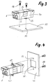
- Figure 2 shows a similar arrangement as Figure 1, but on Example of a simplex connector with only one Plug on each side of the socket part 1.
- the socket part and the associated brackets are accordingly narrower, but have the same locking and Fasteners, such as the bracket of the duplex version.
- Brackets 5b, 5f and 5g possible as a simplex version.
- Figure 3 shows how the bracket 5a with the socket part 1 a horizontal support plate 30 is screwed.
- the two Fixing screws 18 penetrate through the tabs 23 and Bores 35 in the carrier plate.
- the Bracket essentially over the entire surface of the housing of the socket part 1 so that no gaps or voids remain, in which dirt can accumulate. This applies Incidentally, also for the other variants of the brackets.
- Figure 4 shows a bracket 5d on a vertical Carrier plate 30 can be attached.
- tongues 17 are cut directly into threads, into which the fastening screws 18 are screwed can be.
- the carrier plate 30 is with a Provide opening 31 which the bracket 5d or the socket part 1 fits perfectly.
- Figure 5 shows the holder 5e, which is also on a vertical Carrier plate 30 can be fixed.
- the screw connection is a snap connection.
- This consists of a resilient clamping bracket 19 and one Abutment 20 in each U-leg 11 or 11 '.
- the bracket 5f shown in Figure 6 works in Principle in the same way as the bracket 5e.
- abutments 22 are arranged on the end face 16 and the clamps 21 lie between two abutments.
- the socket part be completely sunk inside a device so that only the insertion section of the socket part 1 is visible is.
- FIG. 9 shows how the holder 5g in the direction of the arrow can be pivoted up about the axis section 33. This can be used for devices that are difficult to access Insertion process can be facilitated.
- FIG 10 finally shows an alternative embodiment, with the edge on both side walls 3 and 4 Elevations 8, 8 'and 8a, 8a' are arranged. Analogous are in the lying in the vertical plane 29 Mounts also corresponding recesses 13a, 13a ' intended. Those lying on the horizontal plane 28 Mounts require the additional recesses 32a, 32a 'for Recording the elevations 8a, 8a '.
Abstract
Description
Die Erfindung betrifft ein optisches Modul, insbesondere
Buchsenteil für eine optische Steckverbindung gemäss dem
Oberbegriff von Anspruch 1. Die Halterung erfüllt dabei den
Zweck, das selber nicht mit Haltemitteln ausgerüstete Modul
aufzunehmen und auf einer Trägerplatte, beispielsweise auf
einer gedruckten Schaltung oder an einer Gerätewand zu befestigen.
Beim Buchsenteil kann es sich um eine Durchführungskupplung
handeln, welche von beiden Seiten einen optischen
Stecker aufnehmen kann. Alternativ könnte das Buchsenteil
aber auch als Receptacle ausgebildet sein, bei dem ein einseitig
eingesteckter Stecker Licht auf ein festmontiertes
optisches Element sendet bzw. Licht von diesem Element empfängt.The invention relates to an optical module, in particular
Socket part for an optical connector according to the
Preamble of
Ein gattungsmässig vergleichbares Modul und eine dazugehörige Halterung ist beispielsweise durch die DE U 297 08 275 bekannt geworden. Ein Nachteil dieser Ausführungsform besteht darin, dass die Befestigung auf der Trägerplatte nur auf eine einzige Art und Weise möglich ist, nämlich mit gegen die Trägerplatte gerichteten U-Schenkeln der Halterung. Ausserdem ist diese bekannte Halterung dazu bestimmt, mit der Trägerplatte verlötet zu werden, was ein rasches Auswechseln verunmöglicht.A generic comparable module and an associated one Bracket is known for example from DE U 297 08 275 become. A disadvantage of this embodiment is in that the attachment to the support plate only on one only way is possible, namely with against Carrier plate directed U-legs of the bracket. Furthermore this known holder is intended to be used with the carrier plate to be soldered, which makes rapid replacement impossible.
Es ist daher eine Aufgabe der Erfindung, ein optisches Modul
der eingangs genannten Art zu schaffen, das auf unterschiedliche
Weise in der U-förmigen Halterung fixiert werden kann
und das daher auch vielseitiger einsetzbar ist. Diese Aufgabe
wird erfindungsgemäss mit einem Modul gelöst, das die Merkmale
im Anspruch 1 aufweist. Die auf verschiedenen Seiten
angeordneten Rastmittel ermöglichen es, die Halterungen auf
sich kreuzenden Ebenen auf das Gehäuse aufzuschnappen. Zwar
kann dabei an einem Modul nur eine einzige Halterung aufgeschnappt
werden, wobei die Rastmittel auf einer Seitenwand
bzw. auf zwei parallelen Seitenwänden zum Einsatz kommen und
die Rastmittel auf den übrigen Seitenwänden funktionslos
bleiben. Mit dem gleichen Modul ist jedoch eine Vielzahl von
Befestigungsmöglichkeiten gewährleistet, wobei die Halterungen
nicht zwingend mit den U-Schenkeln gegen die Trägerplatte
gerichtet sein müssen. Auch parallel zur Tägerplatte verlaufende
U-Schenkel oder gar von der Tägerplatte weggerichtete
U-Schenkel sind grundsätzlich denkbar.It is therefore an object of the invention to provide an optical module
of the type mentioned at the outset to create different
Way can be fixed in the U-shaped bracket
and that is therefore more versatile. This task
is solved according to the invention with a module that has the features
in
Zur Fixierung des optischen Moduls in Längsrichtung kann an den beiden Endabschnitten des Gehäuses je ein wenigstens teilweise umlaufender Kragen als Seitenbegrenzung für die Halterung angeordnet sein. Wenn das Gehäuse aus Kunststoffmaterial hergestellt ist, kann der Kragen einstückig mit dem Gehäuse ausgebildet sein.To fix the optical module in the longitudinal direction on the two end sections of the housing at least one partially circumferential collar as a side boundary for the Bracket can be arranged. If the housing is made of plastic material is made, the collar can be made in one piece with the Housing be formed.
Die Rastelemente können wenigstens an einer Seitenwand durch an den Endabschnitten des Gehäuses angeordnete Erhebungen gebildet werden, welche in korrespondierende Ausnehmungen an der Halterung angreifen. Diese Erhebungen können dabei zungenartig aus den oben erwähnten Kragen herauswachsen und ihre Dicke entspricht vorzugsweise der Wandstärke der Halterung. Diese randseitigen Erhebungen können an sämtlichen Seitenwänden des Gehäuses angeordnet sein.The latching elements can pass through at least one side wall Elevations arranged on the end sections of the housing are formed, which in corresponding recesses the bracket. These surveys can be tongue-like grow out of the collar mentioned above and hers Thickness preferably corresponds to the wall thickness of the holder. These elevations on the edge can be on all side walls of the housing.
Alternativ oder kombiniert mit den erwähnten Erhebungen können die Rastelement aber auch wenigstens an einer Seitenwand durch wenigstens eine im Grundriss vorzugsweise rechteckige Erhebung gebildet werden, die an wenigstens einem Abschnitt in eine Ausnehmung an der Halterung eingreift. Diese Erhebung kann ebenfalls einstückig mit der Gehäuseseitenwand ausgebildet sein und sie kann noch die zusätzliche Funktion haben, die betreffende Seitenwand zu verstärken.Alternatively or in combination with the surveys mentioned can the locking element but also at least on one side wall by at least one, preferably rectangular in plan Survey formed on at least one Section engages in a recess on the bracket. This elevation can also be made in one piece with the housing side wall be trained and it can be the additional Function to reinforce the relevant side wall.
Schliesslich können die Rastmittel wenigstens an einer Seitenwand durch wenigstens eine Vertiefung insbesondere einen Schlitz, gebildet werden, welche eine Klaue an der Halterung aufnimmt.Finally, the locking means can at least on one side wall by at least one depression, in particular one Slot, which are formed by a claw on the bracket records.
Die Erfindung betrifft auch eine Vorrichtung zum Befestigen
eines optischen Moduls an einer Trägerplatte mit den Merkmalen
der unabhängigen Ansprüche 6, 10, 11 und 12. Die U-förmige
Halterung kann dabei an den Stirnseiten an wenigstens
einem U-Schenkel wenigstens je eine Ausnehmung aufweisen,
welche der Einrastung der Halterung dienen. Sie kann aber
auch noch am Wandabschnitt, der die beiden U-Schenkel miteinander
verbindet eine Öffnung aufweisen. Diese dient der
Aufnahme der nicht benötigten Erhebung an der Seitenwand des
Gehäuses, aber auch der Gewichtseinsparung.The invention also relates to a device for fastening
an optical module on a carrier plate with the features
of
Die Befestigungsmittel zum Verbinden der Halterung mit der Trägerplatte könne je nach Anwendungszweck ganz unterschiedlich ausgebildet sein. Es kann sich um Schraubverbindungen, Schnappverbindungen aber auch um Scharniere für eine bewegliche Befestigung handeln. Selbstverständlich können auch die konventionellen Lötfüsse nach wie vor eingesetzt werden.The fasteners for connecting the bracket to the Carrier plate can vary widely depending on the application be trained. It can be screw connections, Snap connections but also around hinges for a movable Act attachment. Of course you can conventional soldering feet are still used.
Besonders vorteilhaft verlaufen die beiden U-Schenkel der Halterung im wesentlichen planparallel zueinander, so dass eine vollflächige Anlage an den Seitenwänden des Moduls möglich ist. Damit wird das Eindringen von Staub und Schmutz in verbleibende Zwischenräume verhindert. Da die Halterung in der Regel ein Biegeteil aus Metallblech ist, wird dadurch ausserdem der Biegevorgang vereinfacht. Selbstverständlich könnten die Halterungen aber auch Spritzgussteile aus Kunststoffmaterial sein.The two U-legs are particularly advantageous Bracket essentially plane-parallel to each other, so that a full-surface system on the side walls of the module is possible. This will prevent dust and dirt from entering prevented in remaining gaps. Since the bracket in is usually a bent part made of sheet metal moreover, the bending process is simplified. Of course the brackets could also be injection molded parts made of plastic material his.
Weitere Vorteile und Einzelmerkmale der Erfindung ergeben sich aus den Zeichnungen und aus der nachfolgenden Beschreibung von Ausführungsbeispielen. Es zeigen:
Figur 1- eine perspektivische Darstellung eines Duplex-Buchsenteils mit einer Vielzahl unterschiedlichen Halterungen,
- Figur 2
- eine perspektivische Darstellung eines Simplex-Buchsenteils mit einer Vielzahl unterschiedlichen Halterungen,
Figur 3- eine Halterung mit Schraubenbefestigung auf einer horizontalen Trägerplatte,
Figur 4- eine Halterung mit Schraubenbefestigung an einer vertikalen Trägerplatte,
- Figur 5
- eine Halterung mit mittiger Klemmbefestigung an einer vertikalen Trägerplatte,
Figur 6- eine Halterung mit endseitiger Klemmbefestigung an einer vertikalen Trägerplatte,
- Figur 7
- eine Halterung mit Scharnierbefestigung auf einem Achsabschnitt,
Figur 8- eine vergrösserte Draufsicht aus Pfeilrichtung A der Scharnierbefestigung gemäss Figur 7,
Figur 9- eine schematische Seitenansicht der Halterung gemäss Figur 7 in zwei verschiedenen Positionen und,
Figur 10- eine perspektivische Darstellung eines Buchsenteils mit alternativen Rastmitteln und mit zwei komplementären Halterungen.
- Figure 1
- 1 shows a perspective illustration of a duplex socket part with a multiplicity of different holders,
- Figure 2
- 1 shows a perspective illustration of a simplex socket part with a multiplicity of different holders,
- Figure 3
- a bracket with screw fastening on a horizontal support plate,
- Figure 4
- a bracket with screw fastening on a vertical support plate,
- Figure 5
- a holder with a central clamp on a vertical support plate,
- Figure 6
- a holder with an end clamp on a vertical support plate,
- Figure 7
- a bracket with hinge attachment on one axle section,
- Figure 8
- 7 shows an enlarged top view from arrow direction A of the hinge fastening according to FIG. 7,
- Figure 9
- 7 shows a schematic side view of the holder according to FIG. 7 in two different positions, and
- Figure 10
- a perspective view of a socket part with alternative locking means and with two complementary brackets.
In Figur 1 ist ein typisches Buchsenteil 1 für eine optische
Steckverbindung dargestellt und zwar in einer Duplexversion,
zur Aufnahme je eines Steckerpaars 27 von beiden Seiten her.
Das Buchsenteil verfügt über ein etwa quaderförmiges Gehäuse
2, das die hier nicht dargestellten Elemente zum Zentrieren
der gegeneinander gerichteten Steckerstifte aufnimmt. Das
Gehäuse verfügt über horizontale Seitenwände 3 und vertikale
Seitenwände 4. Diese liegen ersichtlicherweise auf den sich
im rechten Winkel kreuzenden Ebenen 28 und 29.In Figure 1 is a
Das Buchsenteil 1 ist mit Endabschnitten 6, 6' versehen,
welche je einen umlaufenden Kragen 7, 7' aufweisen, der sich
etwas über die Seitenwände 3 und 4 erhebt. An den Seitenwänden
3 sind etwa in der Mitte zungenartige Erhebungen 8, 8'
angeordnet, die einstückig mit den Kragen ausgebildet sind.
Auf der gleichen Achse der Erhebungen 8, 8' ist in den Seitenwänden
3 auch ein in der Mitte unterbrochener Schlitz 10
angeordnet. Etwa im Zentrum der Seitenwände 4 ist je eine im
Grundriss rechteckige Erhebung 9 vorgesehen.The
Auf den sich kreuzenden Ebenen 28 und 29 sind mehrere Typen
von Halterungen 5a, 5b, 5c, 5d, 5e, 5f und 5g dargestellt.
Die Halterungen 5a, 5b und 5c können in Pfeilrichtung x von
oben auf das Buchsenteil aufgeschnappt werden. Die Halterungen
5d, 5e und 5f sind in Pfeilrichtung z seitlich auf das
Buchsenteil aufzuschnappen und die Halterung 5g kann in
Pfeilrichtung y von unten aufgeschnappt werden. Die Befestigung
einzelner Halterungen auf einer Trägerplatte wird nachstehend
noch genauer beschrieben. Mit Ausnahme der Halterung
5c handelt es sich jeweils um lösbare Verbindungen.There are several types on the
Sämtliche Halterungen sind etwa U-förmig ausgebildet und
verfügen über die beiden U-Schenkel 11, 11' und einen die U-Schenkel
verbindenden Verbindungsabschnitt 12. Die Halterungen
auf der Ebenen 29 verfügen in den U-Schenkeln über je
eine mittige Ausnehmung 15. Diese Ausnehmungen haben etwa die
Breite der Erhebungen 9 am Buchsenteil und die Unterkante der
Ausnehmungen ist so beschaffen, dass sie unter einer Erhebung
9 einrastet. Die auf dieser Ebene liegenden Halterungen
verfügen an der Stirnseite 16, 16' auch über je eine Zusatzausnehmung
32, 32' am Verbindungsabschnitt 12. Diese Zusatzausnehmungen
haben keine eigentliche Haltefunktion, sondern
sind nur dazu bestimmt, die Endseitigen Erhebungen 8, 8' am
Buchsenteil 1 aufzunehmen.All brackets are approximately U-shaped and
have the two U-legs 11, 11 'and one the U-legs
connecting connecting
Die auf der Ebenen 28 liegenden Halterung verfügen an den
Stirnseiten 16, 16' an den U-Schenkeln 11, 11' ebnfalls über
Ausnehmungen 13,13'. Diese haben jedoch die Funktion, in die
Erhebungen 8, 8' am Buchsenteil 1 einzurasten und damit die
Halterungen auf dem Buchsenteil zu fixieren. Dagegen ist die
Öffnung 14 am Verbindungsabschnitt 12 nur dazu bestimmt die
Erhebung 9 in der Mitte des Buchsenteils aufzunehmen.The lying on the
Die Halterung 5a verfügt über seitliche Laschen 23, welche
eine Befestigungsschraube aufnehmen können.The
Die Halterung 5b ist auf der Innenseite mit Rastnocken 24
versehen. Diese können beispielsweise in einen Aufsatz auf
einer Trägerplatte eingerastet werden.The holder 5b is on the inside with locking
Die Halterung 5c ist mit Lötfüssen 25 versehen, welche in
eine Platine eingelötet werden können. Im eingelöteten Zustand
kann dabei allerdings das Buchsenteil 1 nicht mehr
entfernt werden.The
Die Halterung 5d verfügt ebenfalls über seitliche Materialzungen
17 zur Aufnahme von Befestigungsschrauben.The
Die Halterungen 5e und 5f können über eine nachstehend noch
genauer beschriebene Klemmbefestigung fixiert werden und die
Halterung 5g weist eine Scharnierklammer 26 auf, die nachstehend
ebenfalls noch genauer beschrieben wird.
Sämtliche Halterungen sind so ausgebildet, dass sie mit ihren
Stirnseiten 16, 16' zwischen die umlaufenden Kragen 7, 7' am
Buchsenteil 1 passen.The
Figur 2 zeigt eine ähnliche Anordnung wie Figur 1, jedoch am
Beispiel einer Simplexsteckverbindung mit nur einem einzigen
Stecker auf jeder Seite des Buchsenteils 1. Das Buchsenteil
und die dazu gehörigen Halterungen sind dementsprechend
schmaler ausgebildet, verfügen aber über die gleichen Rast- und
Befestigungsmittel, wie die Halterung der Duplexversion.
Selbstverständlich sind auch die hier nicht dargestellten
Halterungen 5b, 5f und 5g als Simplexversion möglich.Figure 2 shows a similar arrangement as Figure 1, but on
Example of a simplex connector with only one
Plug on each side of the
Figur 3 zeigt wie die Halterung 5a mit dem Buchsenteil 1 auf
eine horizontale Trägerplatte 30 geschraubt wird. Die beiden
Befestigungsschrauben 18 dringen durch die Laschen 23 und die
Bohrungen 35 in der Trägerplatte. Wie dargestellt, liegt die
Halterung im wesentlichen vollflächig am Gehäuse des Buchsenteils
1 an, so dass keine Zwischenräume bzw. Hohlräume verbleiben,
in denen sich Schmutz ansammeln kann. Dies gilt
übrigens auch für die übrigen Varianten der Halterungen.Figure 3 shows how the
Figur 4 zeigt eine Halterung 5d, die an einer vertikalen
Trägerplatte 30 befestigt werden kann. In die beiden seitlich
abstehenden Materialzungen 17 sind direkt Gewinde eingeschnitten,
in welche die Befestigungsschrauben 18 eingeschraubt
werden können. Die Trägerplatte 30 ist mit einer
Öffnung 31 versehen, welche die Halterung 5d bzw. das Buchsenteil
1 passgenau aufnimmt.Figure 4 shows a
Figur 5 zeigt die Halterung 5e, die ebenfalls an einer vertikalen
Trägerplatte 30 fixiert werden kann. An die Stelle
der Schraubverbindung tritt jedoch eine Schnappverbindung.
Diese besteht aus je einem federnden Klemmbügel 19 und einem
Widerlager 20 in jedem U-Schenkel 11 bzw. 11'. Beim Einschieben
der Halterung 5e in die Öffnung 31 werden die Klemmbügel
niedergedrückt, bis die Widerlager 20 die Trägerplatte erreicht
haben. Dann federn die Klemmbügel wieder nach aussen
und verspannen auf die Weise die Halterung in der Öffnung 31.Figure 5 shows the
Die in Figur 6 dargestellte Halterung 5f funktioniert im
Prinzip auf die gleiche Weise wie die Halterung 5e. Die
Widerlager 22 sind jedoch an der Stirnseite 16 angeordnet und
die Klemmbügel 21 liegen zwischen zwei Widerlagern. Mit einer
derartigen Halterung kann das Buchsenteil beispielsweise
vollständig im Innern eines Geräts versenkt werden, so dass
nur noch der Einführungsabschnitt des Buchsenteils 1 sichtbar
ist.The bracket 5f shown in Figure 6 works in
Principle in the same way as the
In den Figuren 7 bis 9 ist die Konstruktion und Funktion der
Halterung 5g dargestellt. Die verfügt über eine Scharnierklammer
26, welche einstückig mit dem Verbindungsabschnitt 12
ausgebildet ist. Zu diesem Zweck ist stirnseitig eine Schürze
34 abgebogen, der an beiden Enden je ein Bügel 35 gegenübersteht.
Auf diese Weise kann die Scharnierklammer 26 einen
Achsabschnitt 33 klemmend erfassen der beispielsweise an
einer geräteseitigen Achshalterung 36 befestigt ist.In Figures 7 to 9, the construction and function of the
In Figur 9 ist dargestellt, wie die Halterung 5g in Pfeilrichtung
um den Achsabschnitt 33 hochgeschwenkt werden kann.
Damit kann beispielsweise bei schwer zugänglichen Geräten der
Einsteckvorgang erleichtert werden.FIG. 9 shows how the
Figur 10 zeigt schliesslich noch ein alternatives Ausführungsbeispiel,
bei dem an beiden Seitenwänden 3 und 4 randseitige
Erhebungen 8, 8' bzw. 8a, 8a' angeordnet sind. Sinngemäss
sind in den in der vertikalen Ebene 29 liegenden
Halterungen auch korrespondierende Ausnehmungen 13a, 13a'
vorgesehen. Die auf der horizontalen Ebene 28 liegenden
Halterungen benötigen die Zusatzausnehmungen 32a, 32a' zur
Aufnahme der Erhebungen 8a, 8a'.Figure 10 finally shows an alternative embodiment,
with the edge on both
Claims (14)
Priority Applications (2)
| Application Number | Priority Date | Filing Date | Title |
|---|---|---|---|
| DE59814429T DE59814429D1 (en) | 1998-07-21 | 1998-07-21 | Optical module for an optical connector |
| EP98810702A EP0974854B1 (en) | 1998-07-21 | 1998-07-21 | Optical module for an optical plug connection |
Applications Claiming Priority (1)
| Application Number | Priority Date | Filing Date | Title |
|---|---|---|---|
| EP98810702A EP0974854B1 (en) | 1998-07-21 | 1998-07-21 | Optical module for an optical plug connection |
Publications (2)
| Publication Number | Publication Date |
|---|---|
| EP0974854A1 true EP0974854A1 (en) | 2000-01-26 |
| EP0974854B1 EP0974854B1 (en) | 2010-01-27 |
Family
ID=8236207
Family Applications (1)
| Application Number | Title | Priority Date | Filing Date |
|---|---|---|---|
| EP98810702A Expired - Lifetime EP0974854B1 (en) | 1998-07-21 | 1998-07-21 | Optical module for an optical plug connection |
Country Status (2)
| Country | Link |
|---|---|
| EP (1) | EP0974854B1 (en) |
| DE (1) | DE59814429D1 (en) |
Cited By (2)
| Publication number | Priority date | Publication date | Assignee | Title |
|---|---|---|---|---|
| EP1978386A2 (en) | 2007-04-03 | 2008-10-08 | Diamond SA | Coupling unit for a connector |
| EP2741114A1 (en) * | 2012-12-04 | 2014-06-11 | Sercomm Corporation | Mounting assembly for optical fiber flange |
Citations (11)
| Publication number | Priority date | Publication date | Assignee | Title |
|---|---|---|---|---|
| US4986762A (en) * | 1989-08-15 | 1991-01-22 | Minnesota Mining And Manufacturing Company | Termination module for use in an array of modules |
| DE4329824A1 (en) * | 1992-09-04 | 1994-03-17 | Honda Tsushin Kogyo | Adaptor for optical fibre connection to circuit board - has two identical adaptor elements sandwiched about alignment sleeve contained in sleeve holder, and with snap fitting elements |
| EP0597501A1 (en) * | 1992-11-13 | 1994-05-18 | International Business Machines Corporation | Fiber optic connector housing |
| DE29512773U1 (en) * | 1995-08-08 | 1995-10-12 | Diamond Sa | Holder for fastening an optical module, in particular a socket part for an optical connector on a circuit board |
| EP0696748A2 (en) * | 1994-08-12 | 1996-02-14 | The Furukawa Electric Co., Ltd. | Method of collectively connecting multiple optical connectors and aligning and positioning jig for multiple optical connectors used in the method |
| DE29504575U1 (en) * | 1995-03-07 | 1996-07-11 | Siemens Ag | One-piece holder for detachable surface mounting |
| EP0730177A2 (en) * | 1995-02-28 | 1996-09-04 | AT&T Corp. | Patch panel and collar for optical fiber couplers |
| DE29614436U1 (en) * | 1996-08-20 | 1996-10-10 | Diamond Sa | Holder for attaching an optical module, in particular a socket part for an optical connector on a circuit board |
| DE29708275U1 (en) * | 1997-05-07 | 1997-07-17 | Siemens Ag | Device for fastening couplings for plugs of optical fiber cables |
| WO1997034176A1 (en) * | 1996-03-12 | 1997-09-18 | Diamond S.A. | Connector with a plurality of parallel optical waveguides |
| US5757998A (en) * | 1996-10-02 | 1998-05-26 | International Business Machines Corporation | Multigigabit adaptable transceiver module |
Family Cites Families (3)
| Publication number | Priority date | Publication date | Assignee | Title |
|---|---|---|---|---|
| JP2588720Y2 (en) * | 1992-10-19 | 1999-01-13 | ミツミ電機株式会社 | Optical fiber connector |
| JP3099113B2 (en) * | 1996-11-13 | 2000-10-16 | モレックス インコーポレーテッド | Optical fiber plug and optical connector |
| US5764043A (en) * | 1996-12-20 | 1998-06-09 | Siecor Corporation | Traceable patch cord and connector assembly and method for locating patch cord ends |
-
1998
- 1998-07-21 EP EP98810702A patent/EP0974854B1/en not_active Expired - Lifetime
- 1998-07-21 DE DE59814429T patent/DE59814429D1/en not_active Expired - Lifetime
Patent Citations (11)
| Publication number | Priority date | Publication date | Assignee | Title |
|---|---|---|---|---|
| US4986762A (en) * | 1989-08-15 | 1991-01-22 | Minnesota Mining And Manufacturing Company | Termination module for use in an array of modules |
| DE4329824A1 (en) * | 1992-09-04 | 1994-03-17 | Honda Tsushin Kogyo | Adaptor for optical fibre connection to circuit board - has two identical adaptor elements sandwiched about alignment sleeve contained in sleeve holder, and with snap fitting elements |
| EP0597501A1 (en) * | 1992-11-13 | 1994-05-18 | International Business Machines Corporation | Fiber optic connector housing |
| EP0696748A2 (en) * | 1994-08-12 | 1996-02-14 | The Furukawa Electric Co., Ltd. | Method of collectively connecting multiple optical connectors and aligning and positioning jig for multiple optical connectors used in the method |
| EP0730177A2 (en) * | 1995-02-28 | 1996-09-04 | AT&T Corp. | Patch panel and collar for optical fiber couplers |
| DE29504575U1 (en) * | 1995-03-07 | 1996-07-11 | Siemens Ag | One-piece holder for detachable surface mounting |
| DE29512773U1 (en) * | 1995-08-08 | 1995-10-12 | Diamond Sa | Holder for fastening an optical module, in particular a socket part for an optical connector on a circuit board |
| WO1997034176A1 (en) * | 1996-03-12 | 1997-09-18 | Diamond S.A. | Connector with a plurality of parallel optical waveguides |
| DE29614436U1 (en) * | 1996-08-20 | 1996-10-10 | Diamond Sa | Holder for attaching an optical module, in particular a socket part for an optical connector on a circuit board |
| US5757998A (en) * | 1996-10-02 | 1998-05-26 | International Business Machines Corporation | Multigigabit adaptable transceiver module |
| DE29708275U1 (en) * | 1997-05-07 | 1997-07-17 | Siemens Ag | Device for fastening couplings for plugs of optical fiber cables |
Cited By (3)
| Publication number | Priority date | Publication date | Assignee | Title |
|---|---|---|---|---|
| EP1978386A2 (en) | 2007-04-03 | 2008-10-08 | Diamond SA | Coupling unit for a connector |
| EP1978386A3 (en) * | 2007-04-03 | 2009-03-11 | Diamond SA | Coupling unit for a connector |
| EP2741114A1 (en) * | 2012-12-04 | 2014-06-11 | Sercomm Corporation | Mounting assembly for optical fiber flange |
Also Published As
| Publication number | Publication date |
|---|---|
| EP0974854B1 (en) | 2010-01-27 |
| DE59814429D1 (en) | 2010-03-18 |
Similar Documents
| Publication | Publication Date | Title |
|---|---|---|
| DE60131723T2 (en) | Floating mounted connector assembly | |
| DE3423235C2 (en) | Fastening device | |
| DE102009045722B4 (en) | Component carrier | |
| DE102007038787A1 (en) | Lamp module for semiconductor light sources-lamps for vehicle, has cooling body, with carrier part, which is arranged on cooling body and supports semiconductor light source | |
| DE10340571B3 (en) | Clamp for holding flat objects | |
| DE10313358B3 (en) | Electrical patch panel for mounting on wall or within component module rack supported by fixing angles at opposite ends of patch panel housing | |
| DE3600361A1 (en) | Substrate holder of integral construction | |
| DE19806690A1 (en) | Mounting system for a component to a carrier plate | |
| EP1427310B1 (en) | Drawer comprising removable section attachments | |
| DE3832468A1 (en) | EYEWEAR FRAME WITH LOCKABLE TRY-ON NOSE PIECE | |
| EP0702441A1 (en) | Electrical installation apparatus, especially for cable ducts | |
| DE102020211730B3 (en) | Housing for an electronic circuit arranged on a printed circuit board | |
| EP0974854A1 (en) | Optical fibre module and device for fixing it to a carrier board | |
| DE102011107610A1 (en) | Conductor holder for attachment to a carrier of an aircraft structure | |
| DE19839118C2 (en) | Construction arrangement for fastening a component on a printed circuit board and electronic devices with this construction | |
| EP2818733B1 (en) | Fastening element, fastening system with the fastening element and method for fitting a light holder with an electronic module by means of the fastening system | |
| DE202021104596U1 (en) | housing system | |
| DE4138047C2 (en) | Device for connecting several parts | |
| WO2004012961A1 (en) | System for fixing headlights on a carrier part of a vehicle | |
| DE102020208118B4 (en) | PCB mount, method, system and use | |
| DE3844310C2 (en) | ||
| EP0446575A2 (en) | Mounting plate, especially for telecommunication and data processing casings | |
| DE102016115898B4 (en) | Arrangement for fastening printed circuit boards | |
| DE4137687C2 (en) | ||
| DE19516428A1 (en) | Device for securing plug assembly in housing |
Legal Events
| Date | Code | Title | Description |
|---|---|---|---|
| PUAI | Public reference made under article 153(3) epc to a published international application that has entered the european phase |
Free format text: ORIGINAL CODE: 0009012 |
|
| AK | Designated contracting states |
Kind code of ref document: A1 Designated state(s): CH DE FR GB IT LI NL |
|
| AX | Request for extension of the european patent |
Free format text: AL;LT;LV;MK;RO;SI |
|
| 17P | Request for examination filed |
Effective date: 20000309 |
|
| AKX | Designation fees paid |
Free format text: CH DE FR GB IT LI NL |
|
| 17Q | First examination report despatched |
Effective date: 20071227 |
|
| RTI1 | Title (correction) |
Free format text: OPTICAL MODULE FOR AN OPTICAL PLUG CONNECTION |
|
| GRAP | Despatch of communication of intention to grant a patent |
Free format text: ORIGINAL CODE: EPIDOSNIGR1 |
|
| GRAS | Grant fee paid |
Free format text: ORIGINAL CODE: EPIDOSNIGR3 |
|
| GRAA | (expected) grant |
Free format text: ORIGINAL CODE: 0009210 |
|
| AK | Designated contracting states |
Kind code of ref document: B1 Designated state(s): CH DE FR GB IT LI NL |
|
| REG | Reference to a national code |
Ref country code: GB Ref legal event code: FG4D Free format text: NOT ENGLISH |
|
| REG | Reference to a national code |
Ref country code: CH Ref legal event code: EP |
|
| REF | Corresponds to: |
Ref document number: 59814429 Country of ref document: DE Date of ref document: 20100318 Kind code of ref document: P |
|
| REG | Reference to a national code |
Ref country code: CH Ref legal event code: NV Representative=s name: HEPP WENGER RYFFEL AG |
|
| REG | Reference to a national code |
Ref country code: NL Ref legal event code: T3 |
|
| PLBE | No opposition filed within time limit |
Free format text: ORIGINAL CODE: 0009261 |
|
| STAA | Information on the status of an ep patent application or granted ep patent |
Free format text: STATUS: NO OPPOSITION FILED WITHIN TIME LIMIT |
|
| 26N | No opposition filed |
Effective date: 20101028 |
|
| REG | Reference to a national code |
Ref country code: FR Ref legal event code: PLFP Year of fee payment: 19 |
|
| REG | Reference to a national code |
Ref country code: FR Ref legal event code: PLFP Year of fee payment: 20 |
|
| PGFP | Annual fee paid to national office [announced via postgrant information from national office to epo] |
Ref country code: FR Payment date: 20170613 Year of fee payment: 20 |
|
| PGFP | Annual fee paid to national office [announced via postgrant information from national office to epo] |
Ref country code: NL Payment date: 20170712 Year of fee payment: 20 |
|
| PGFP | Annual fee paid to national office [announced via postgrant information from national office to epo] |
Ref country code: DE Payment date: 20170719 Year of fee payment: 20 Ref country code: IT Payment date: 20170720 Year of fee payment: 20 Ref country code: GB Payment date: 20170719 Year of fee payment: 20 Ref country code: CH Payment date: 20170926 Year of fee payment: 20 |
|
| REG | Reference to a national code |
Ref country code: DE Ref legal event code: R071 Ref document number: 59814429 Country of ref document: DE |
|
| REG | Reference to a national code |
Ref country code: NL Ref legal event code: MK Effective date: 20180720 |
|
| REG | Reference to a national code |
Ref country code: CH Ref legal event code: PL |
|
| REG | Reference to a national code |
Ref country code: GB Ref legal event code: PE20 Expiry date: 20180720 |
|
| PG25 | Lapsed in a contracting state [announced via postgrant information from national office to epo] |
Ref country code: GB Free format text: LAPSE BECAUSE OF EXPIRATION OF PROTECTION Effective date: 20180720 |