Field of the Invention
-
The present invention deals with locks and switches
in which pressure-based fingerprint sensor is used.
Background of the Invention
-
Fingerprint matching systems that detect
fingerprints and compare them with fingerprint data in a
stored database have been available in the prior art for
some time now. Such fingerprint identification systems
are being increasingly used in various devices for
identifying users. For example, door locks can be
operated through the matching of fingerprints instead of
ID numbers. This prevents breach of security through
misuse of ID numbers by unauthorized persons. Locks that
use fingerprint matching systems are currently in use.
-
Conventional fingerprint matching systems found in
the prior art, however, have some shortcomings. In
conventional systems, identification is performed by
first sensing the fingerprint data and comparing it with
fingerprint data in a database. So, such systems require
a sensor (hereinafter referred to as "fingerprint
sensor") that detects fingerprint data which can then be
used for matching. In conventional systems, fingerprint
sensors are used which detect the fingerprint data
utilizing the principles of light or electrostatic
capacitance.
-
However, the optical fingerprint sensors sometimes
cannot accurately detect fingerprint data in strong
ambient light, such as when used outdoors during the day.
Also, capacitance-based sensors at times have to cope
with noise because of electromagnetic waves present in
the environment where they are used. Moreover, both types
of prior art fingerprint sensors are prone to error in
the presence of moisture. Therefore, when such sensors
are used outdoors on a wet day or in locations with high
humidity, accurate fingerprint data sometimes cannot be
obtained. Still another limitation is that sweat, grease,
etc. on the finger often affects the detection accuracy
of fingerprint data.
-
Thus, fingerprint sensors based on light or
capacitance have inherent limitations, depending on the
environment in which they are used, i.e., the season,
geographical location, the weather, etc. This type of
lowered detection accuracy of fingerprint data directly
leads to the non-functioning of locks that use such
fingerprint sensors, considerably limiting the possible
applications for such locks. Another problem with
optical fingerprint sensors is that a fairly large-sized
device is required for accurate detection of fingerprint
data. So, optical fingerprint sensors cannot be
conveniently used for as part of a lock for objects that
are relatively small.
-
The present applicant had earlier applied for and
was granted a Japanese Patent (Patent application NO HEI
5-277619/1993 and Patent No. 2557795) for a pressure-based
fingerprint sensor (surface pressure input panel)
which did not depend on optical or capacitance input.
-
The present invention was made in view of the above-described
prior art. Its objective is to overcome the
shortcomings of conventional fingerprint sensors and to
provide locks and switches that use pressure-based
fingerprint sensors which are more reliable than
conventional sensors.
Description of the Invention
-
The present invention includes the components
described below for solving the problems of the prior art.
In short, it comprises a lock equipped with a pressure-based
fingerprint sensor, the lock having a locking
mechanism that can lock or unlock the object that is to
be secured, a pressure-based fingerprint sensor that
detects the fingerprint pattern, a memory device that
maintains registered (enrolled) fingerprint data, a
matching unit that determines whether the fingerprint
data created from the pattern detected by the pressure-based
fingerprint sensor matches with fingerprint data
registered in the memory device, and a control unit that
operates the locking mechanism in response to the
determination made by the matching unit.
-
More simply, when the pressure-based fingerprint
sensor is pressed by a finger, a fingerprint data set is
created on the basis of the sensed fingerprint pattern.
Whether this data set matches the registered fingerprint
data is then determined. If there is a match, the control
unit operates the locking mechanism.
-
The locking mechanism is preferably, for instance, a
latching solenoid. A semiconductor memory, a magnetic
disk, an opto-magnetic disk, a hard disk, etc. may be
used for the memory, but an EEPROM is preferable. The
matching unit may be a digital processor, and the control
unit can consist of a digital processor and an electronic
circuit. The object to be secured can be the object
itself whose movement is to be controlled (such as a
door), or a lock which is attached to such an object, and
the lock can have any type of mechanical configuration.
-
In the present invention, the control unit can be
set up so that it would unlock the locking mechanism and
permit movement of the object when the matching unit
determines that the sensed fingerprint data match with
the registered fingerprint data.
-
The control unit can also be set up so that the
locking mechanism will prevent the movement of the object
when the matching unit determines that the sensed
fingerprint data do not match with the registered
fingerprint data.
-
Also, in the present invention, the matching unit
can be embedded in a single pc board, pc card, integrated
circuit, VLSI, or the like (logic element). In that case,
both the fingerprint pattern detected by the pressure-based
fingerprint sensor and the registered fingerprint
data maintained in the memory are both inputted into the
logic element and the result of the determination by
matching unit is outputted from the logic element and
received by the control unit.
-
This logic element can also house the memory device
and the fingerprint sensor. The logic element is
preferably a pc board.
-
When the logic element and other elements of the
invention are distributed instead of integrated, any
conventional method can be used for transmission of data
(communication) between the matching unit and control
unit. For example, the matching unit and the control
unit can communicate electrically, or through wireless,
infrared, magnetic coupling, or static electricity-based
systems.
-
The present invention is broad enough to include
switching systems equipped with a pressure-based
fingerprint sensor consisting of a switch that
electrically connects electrical and electronic devices,
a pressure-based fingerprint sensor that detects the
fingerprint pattern, a memory device that maintains
registered fingerprint data, a matching unit that
determines whether the fingerprint data set created from
the pattern detected by the pressure-based fingerprint
sensor matches the fingerprint data registered in the
memory device, and a control unit that operates the
switch when the matching unit decides that the
fingerprint data match.
-
The present invention is also broad enough to
include switching systems equipped with pressure-based
fingerprint sensors which consist of a switch that
electrically disconnects electrical or electronic devices,
a pressure-based fingerprint sensor that detects the
fingerprint pattern, a memory device that maintains
registered fingerprint data, a matching unit that
determines whether the fingerprint data set created from
the pattern detected by the pressure-based fingerprint
sensor matches fingerprint data registered in the memory
device, and a control unit that operates the switch to
turn off the power when the matching unit decides that
the fingerprint data match.
-
In this embodiment of the invention, some of the
elements can be contained in a single logic element. Any
known method may be used for data transmission between
the matching unit and the control unit.
-
The present invention also comprises a controller
that outputs signals for operating a locking mechanism to
the control device of the locking mechanism, where the
controller is equipped with a pressure-based fingerprint
sensor that detects the fingerprint pattern, a memory
device that maintains registered fingerprint data, a
matching unit that determines whether the fingerprint
data set created from the fingerprint pattern detected by
the pressure-based fingerprint sensor matches with
fingerprint data registered in the memory device, and a
transmission unit that transmits the result of the
matching to the control device as a signal for operating
the locking mechanism.
-
The present invention also comprises a controller
that outputs signals for operating a control device that
switches power to an electrical or electronic device,
where the controller is equipped with a pressure-based
fingerprint sensor that detects the fingerprint pattern,
a memory device that maintains registered fingerprint
data, a matching unit that determines whether the
fingerprint data set created from the pattern detected by
pressure-based the fingerprint sensor matches with
fingerprint data registered in the memory device, and a
transmission unit that transmits an operating signal to
the control device to actuate the power supply switch,
when the matching unit determines that the fingerprint
data match.
-
The present invention also comprises a controller
that outputs signals for operating a control device that
disconnects power to an electrical or electronic device,
where the controller is equipped with a pressure-based
fingerprint sensor that detects the fingerprint pattern,
a memory device that maintains registered fingerprint
data, a matching unit that determines whether the
fingerprint data set created from the pattern detected by
the pressure-based fingerprint sensor matches with
fingerprint data registered in the memory device, and a
transmission unit that transmits an operating signal to
the control device to operate the switch disconnect power
when the matching unit decides that the fingerprint data
match.
Brief Description of the Drawings
-
- Figure 1 depicts a schematic diagram of a lock in
which a pressure-based fingerprint sensor is used, in
Application Mode 1 of the present invention.
- Figure 2 depicts a schematic diagram of the sensor
used in the system shown in Figure 1.
- Figure 3 depicts a flow chart of the processing in
the matching circuit shown in Figure 1.
- Figure 4 depicts a diagram that explains Example 1
of an application of the present invention.
- Figure 5 depicts a functional block diagram of
Example 1.
- Figure 6 depicts a diagram that explains Example 2
of an application of the present invention.
- Figure 7 depicts a diagram that explains Example 3
of an application of the present invention.
- Figure 8 depicts another diagram that explains
Example 3 of an application of the present invention.
- Figure 9 depicts a diagram that explains Example 4
of an application of the present invention.
- Figure 10 depicts a diagram that explains Example 5
of an application of the present invention.
- Figure 11 depicts a diagram that explains Example 6
of an application of the present invention.
- Figure 12 depicts another diagram that explains
Example 6 of an application of the present invention.
- Figure 13 depicts a diagram that explains Example 7
of an application of the present invention.
- Figure 14 depicts a diagram that explains Example 8
of an application of the present invention.
- Figure 15 depicts another diagram that explains
Example 8 of an application of the present invention.
- Figure 16 depicts a diagram that explains Example 9
of an application of the present invention.
- Figure 17 depicts another diagram that explains
Example 9 of an application of the present invention.
- Figure 18 depicts a diagram that explains Example 10
of an application of the present invention.
- Figure 19 depicts another diagram that explains
Example 10 of an application of the present invention.
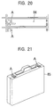
- Figure 20 depicts a diagram that explains Example 11
of an application of the present invention.
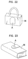
- Figure 21 depicts a diagram that explains Example 12
of an application of the present invention.
- Figure 22 depicts another diagram that explains
Example 12 of an application of the present invention.
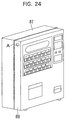
- Figure 23 depicts another diagram that explains
Example 12 of an application of the present invention.
- Figure 24 depicts a diagram that explains Example 13
of an application of the present invention.
- Figure 25 depicts a diagram that explains Example 14
of an application of the present invention.
- Figure 26 depicts a diagram that explains Example 15
of an application of the present invention.
- Figure 27 depicts a diagram that explains Example 16
of an application of the present invention.
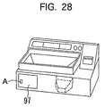
- Figure 28 depicts a diagram that explains Example 16
of an application of the present invention.
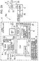
- Figure 29 depicts a schematic diagram of a lock in
which the pressure-based fingerprint sensor is used in
Application Mode 2 of the present invention.
- Figure 30 depicts a diagram showing an alternative
structure for the lock depicted in Figure 29.
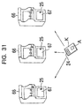
- Figure 31 depicts an example for applying the
present invention to a specific set of devices.
- Figure 32 depicts another example for applying the
present invention to a different set of specific devices.
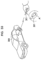
- Figure 33 depicts a diagram that explains Example 17
of an application of the present invention.
- Figure 34 depicts a diagram that explains Example 18
of an application of the present invention.
- Figure 35 depicts a diagram that explains Example 19
of an application of the present invention.
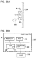
- Figure 36 depicts a diagram that explains Example 20
of an application of the present invention.
- Figure 37 depicts a diagram that explains Example 21
of an application of the present invention.
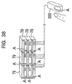
- Figure 38 depicts a diagram that explains Example 22
of an application of the present invention.
- Figure 39 depicts a diagram that explains Example 23
of an application of the present invention.
- Figure 40 depicts a diagram that explains Example 24
of an application of the present invention.
- Figure 41 depicts a diagram that explains Example 25
of an application of the present invention.
- Figure 42 shows a flow chart for the software in the
system depicted in Figure 41.
- Figure 43 depicts a schematic diagram of a switch in
which a pressure-based fingerprint sensor is used in
Application Mode 3 of the present invention.
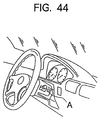
- Figure 44 depicts a diagram that explains Example 26
of an application of the present invention.
- Figure 45 depicts a diagram that explains Example 27
of an application of the present invention.
- Figure 46 depicts a diagram that explains Example 28
of an application of the present invention.
-
Best Modes for Practicing the Invention
-
We shall now explain the best modes of applying the
invention while referring to the drawings.
[Application Mode 1]
-
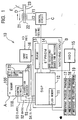
Figure 1 shows a diagram of a lock equipped with a
pressure-based fingerprint sensor 10 (hereinafter this
lock is referred to simply as "sensor lock") in
Application Mode 1 of the new invention. In this Figure,
the sensor lock 10 consists of a sensor unit A, a
matching circuit B connected to A, a control circuit C
(this corresponds to the control unit) connected to B,
and a latching solenoid D (the locking mechanism)
connected to C.
-
The sensor unit A detects the fingerprint pattern of
a finger that is pressed against the sensor. The
matching circuit B matches the fingerprint pattern
detected by A with the pre-registered fingerprint data
and sends the result to the control circuit C. The
control circuit C outputs a control signal, according to
the result of matching done by B, to the latching
solenoid D which acts according to the signal received,
to carry out the unlocking/locking operation of the
concerned object E. We shall now explain the
configuration of each part in greater detail.
〈〈Sensor Unit〉〉
-
As shown in Figure 1, the sensor unit A is an IC
where a pressure-based fingerprint sensor (hereinafter
referred to simply as "sensor") 100, a control circuit
118, an x-direction resistor 160, and a y-direction
resistor 170 are integrated into one chip. A surface
pressure input panel, such as the one that has been
described in Japanese Patent Unexamined Publication NO
Hei 8-68704 (69704/1996) Patent No. 2557795, and a
fingerprint print pattern detection circuit (a control
circuit) are used in the sensor unit A.
-
Figure 2 (a) depicts a structural diagram of the
sensor 100 (surface pressure input panel). Here, the
sensor 100 has a flexible pressure sheet 102 which has a
conductive film 102a at its bottom surface. Sensor 100
also comprises a circuit board 103 in which the scanning
electrodes 130 and 140 are arranged in a matrix pattern
on the insulator base plate 110. A thin film transistor
(TFT) 120 and a conductive contact plate 150 are provided
at each crossing point of the scanning electrode wires
130 and 140. The conductive film 102a of the pressure
sheet 102 is so laminated that it comes in contact with
the conductive contact plates 150 of the circuit board
103. The gate and drain of the TFTs 120 are connected to
the ends of the scanning electrode wires 130 and 140
arranged in a matrix pattern, and the source is connected
to the conductive contact plate 150.
-
Figure 2(b) depicts a diagram explaining the
functioning of the sensor unit A. When the sensor 100 is
pressed by a finger and the scanning signals are sent out
from x-direction resistor 160 and the y-direction
resistor 170, the signal from each detection element, the
main part of which is the TFT 120, is fed to the control
circuit (detector) 118 as a time series and outputted to
the matching circuit B. Here, the signal from each
detection element differs depending on the pressure
applied by the finger on the sensor 100, i.e., depending
on whether it was pressed by a ridge or whether there was
no ridge (valley) at that location in the finger.
Therefore, by expanding the signal from the detection
elements on to an x-y plane according to their location
we can obtain the fingerprint pattern (image data) of the
finger used to press the sensor.
-
In this example, a number of TFTs 120 were
preferably used in the sensor. But thin film diodes may
instead be used.
〈〈Matching Circuit〉〉
-
The matching circuit B shown in Figure 1 is equipped
with a DSP (digital signal processor) 12 which is the
matching unit and has a flash memory 11, a RAM (random
access memory) 13 connected to the DSP 12, and an EEPROM
(electrically erasable programmable ROM) 14 which is the
memory device. The HDD (hard disk) 15, which is also a
memory device, and the input unit 16 are connected to the
matching circuit B.
-
The flash memory 11 preferably maintains the various
control programs that will be executed by the DSP 12.
For example, the flash memory 11 preferably maintains the
programs, like the fingerprint code encoding program 17,
the fingerprint matching program 18, the fingerprint
registering program 19, etc., which are externally loaded.
However, the control programs maintained in the flash
memory can be pre-installed, such as in the form of
built-in firmware.
-
The DSP 12 receives the fingerprint pattern from the
sensor unit A, through the execution of the control
programs 17-19 maintained in the flash memory 11. The DSP
12 is connected to the sensor unit A through signal wires
S1 to S4.
-
The signal wire S1 is used by the DSP 12 to send the
driving clock signals from the clock generation circuit
(not shown) to the control circuit 118 of the sensor unit
A. DSP 12 receives the fingerprint pattern from the
control circuit 118 over signal wire S2. DSP 12 sends the
scanning commands to the x-direction resistor 160 and the
y-direction resistor 170 over signal wires S3 and S4.
-
When the DSP 12 outputs the scanning command through
the signal wires S3 and S4 as in the above setup,
scanning signals are outputted from the x-direction
resistor 160 and the y-direction resistor 170 and the
control circuit 118 which receives the fingerprint
pattern. The DSP 12 then receives, in step with the
driving clock, the fingerprint pattern from the control
circuit 118 through the signal wire S2. Upon receiving
the fingerprint pattern from the sensor unit A, the DSP
12 carries out the process of fingerprint encoding,
matching, registering, etc. These processes will be
discussed again, infra.
-
The RAM 13 is used mainly as the work area of the
DSP 12.
-
The EEPROM 14 maintains the registered fingerprint
codes (registered fingerprint data) used for matching by
the DSP 12. In this application mode, the EEPROM 14 can
maintain about 5 to 10 registered fingerprint codes.
-
The HDD 15 stores the registered fingerprint codes
that are in excess of the capacity of the EEPROM 14 to
store. Thus, the HDD 15 is used only when the registered
fingerprint database is large.
-
The input unit 16 is used to input the ID code
(encoding key) which is used, for instance, when the DSP
12 encodes the fingerprint data. This input unit 16 can
be detachably installed on the matching circuit B or it
can be integrated with B.
-
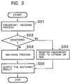
Figure 3 is a flow chart of a typical software for
the DSP 12. The program shown in Figure 3 starts
processing when the DSP 12 receives the fingerprint
pattern from the sensor unit A.
-
Firstly, the DSP 12 executes the fingerprint
encoding step S01 using the fingerprint pattern received
from the sensor unit A. In other words, the DSP 12
extracts a number of characteristic points called
minutiae from the fingerprint pattern. Then, by encoding
the relative positions of each minutia it creates a
fingerprint code, of about 256 bytes for instance.
-
In the next step, the DSP 12 determines whether the
fingerprint code generated in Step S01 is to be recorded
as a registered fingerprint code or not (Step S02). If
it determines that is to be registered (S02; "Yes"), the
processing proceeds to S03. If it decides otherwise
(S02; "No"), the processing proceeds to Step S04.
-
When the DSP 12 advances to Step S03, the
fingerprint code created in Step S01 is stored in an
appropriate area of the EEPROM 14 or the HDD 15 (Step
S03) and the processing is completed.
-
On the other hand, if the DSP 12 advances to S04,
the matching of the fingerprint is carried out. In other
words, DSP 12 reads out the registered fingerprint codes
either from the EEPROM or the HDD and compares them with
the fingerprint code obtained in Step S01 (we shall call
this the "offered fingerprint code") and determines
whether there is a match. If a number of registered
fingerprint codes are maintained in the EEPROM and the
HDD, each registered fingerprint code is compared with
the offered fingerprint code for a possible match.
-
The DSP 12 outputs the result of Step S04 (the
result of the matching) to the control circuit C (Step
S05). In this step, the DSP 12 outputs a "Yes" signal if
there is a match between the offered fingerprint code and
one of the registered fingerprint codes, and a "No"
signal if there is no match.
-
Alternatively, after the DSP 12 asks for the input
of an ID code (encoding key) from the input unit 16 in
Step S01, and the fingerprint code is encoded using this
ID code, the encoded fingerprint may be registered in the
EEPROM 14 or the HDD 15 in Step S03. In this case, the
DSP 12 demands the input of the ID code in Step S04 and
then uses the ID code to decode the fingerprint codes
stored in the EEPROM and the HDD for matching.
-
Alternatively, the system can be set up so that
after the DSP 12 demands the input of the ID code
(encoding key) through the input unit 16 in Step S04, the
inputted ID code and the registered ID codes are compared
and a "Yes" signal is output in Step S05 only if there is
a match between the fingerprint code and the ID code. In
this case, the pre-registered ID code is stored in the
EEPROM 14 for instance.
〈〈Control circuit and the Latching Solenoid〉〉
-
The control circuit C shown in Figure 1 latches in
response to the output signals ("Yes" or "No") from the
matching circuit B. It allows current flow between the
terminal T1 and T2 according to the signal. In other
words, when it receives a "Yes" signal, the control
circuit C passes current from the terminal T1 to the
terminal T2 as a control signal. On the other hand, when
the control circuit C receives a "No" signal, it passes
current from terminal T2 to terminal T1, as a control
signal.
-
The latching solenoid D has coil 21, the ends of
which are connected to the terminals T1 and T2, and a pin
22 that can move inside the coil 21. The concerned
object E, which has to be locked or unlocked, has a
latching hole 23 that is aligned with an end of the pin
22. Here, the part that will be latched by the pin 22
can have any shape as long as it can lock or unlock the
movement of concerned object E.
-
The pin 22 moves away from the concerned object E
when the current flows from the terminal T1 to terminal
T2, completely disengaging the end of the pin 22 and the
hole 23 (Position 1). On the other hand, when the
current flows from terminal T2 to terminal T1, the pin
moves towards the object E, assuming the Position 2 where
one end of the pin 22 engages the hole 23.
-
Therefore, when the pin 22 is in Position 2, the
movement of the object E is restricted or locked. When
pin 22 is in Position 1, on the other hand, the
restriction is removed and the concerned object E is
unlocked.
-
The pin 22 assumes only one of the positions, i.e.,
1 or 2, and retains that position depending on the
control signal from the control circuit C. Pin 22
maintains Position 1 during the time when the control
circuit C receives a "Yes" signal until the time it
receives a "No" signal. Pin 22 remains in Position 2
from the time the control circuit receives a "No" signal
up to the time it receives a "Yes" signal.
-
So, when a user (who may be one of a selected group
of persons) of the above-described sensor lock 10 presses
a finger (the index finger for instance) which
corresponds to one of the registered fingerprint codes,
against the sensor 100, the matching circuit B outputs a
"Yes" signal and the pin 22 assumes Position 1 unlocking
concerned object E. On the other hand, if the user
presses a finger (the middle finger for instance) that
does not correspond to any one of the registered
fingerprint codes, a "No" signal is output by the
matching circuit B and the pin 22 assumes Position 2,
locking object E.
-
Here, the concerned object E that is to be locked or
unlocked can be an object (like a door) itself the
movement of which is to be locked, or a conventional lock
(like a lock attached to a door, etc.) which is attached
to the object the movement of which is to be locked or
unlocked.
-
In this application, the control circuit C is set up
so that the pin 22 of the latching solenoid D shifts its
position depending on a "Yes" or "No" signal received by
the control circuit C. However, it can be set up so that
the pin 22 moves between Position 1 and Position 2 only
when the control circuit receives a "Yes" signal. In
this case, every time the sensor 100 is pressed with a
matching finger, locking or unlocking of the concerned
object E is carried out.
-
In this application mode, we have so far discussed
only the case in which only one matching circuit B is
used. However, more than one matching circuit B may be
provided if a large number of registered fingerprint
codes have to be handled. In that case, the system is
set up so that the offered fingerprint pattern is fed for
verification to each of the matching circuits B and if a
"Yes" signal is output from any one of the circuits B,
then a "Yes" signal is sent to the control circuit C. If
there is no "Yes" signal sent from any of the matching
circuits B, a "No" signal is sent to the control circuit
C. In this manner, the processing can be speeded up and
the response time, from the point when the sensor 100 is
pressed to the time of locking or unlocking of the
concerned object E, can be reduced.
-
The sensor lock 10 can be provided with power
generating component, such as solar cells. It can also
have some power storing element (like batteries) that can
be used to accumulate the power produced by the power
generating component.
-
The sensor lock 10 of Application Mode 1 is not
susceptible to the effects of moisture (humidity in the
atmosphere, rain, sweat, etc.), dryness, greasiness of
the finger, etc. compared to the optical or capacitance-based
sensors, because it uses a pressure-based sensor.
Therefore, the sensor lock 10 can be used irrespective of
the season, geographical location, weather, and other
environmental factors. Moreover, the sensor lock 10 is
far less sensitive to the effect of outdoor light, radio
waves, other electromagnetic waves, etc. compared to
conventional fingerprint sensors, and therefore, it has a
wider applicability. An additional advantage of the
sensor lock 10 is that it is very light, small, short,
and thin and consumes very little power compared to
conventional fingerprint sensors. Therefore, the system
can be miniaturized and the sensor lock 10 can be fitted
with only minor modification to the concerned object E.
-
The sensor lock 10 shown in Figure 1 can be provided
with a warning mechanism like a buzzer, LED or other
display device, light, etc. for indicating when the
fingerprint code does not match, the power level is low,
there is an overflow of memory capacity, the sensor lock
is malfunctioning, etc., or when the sensor 100 is not
properly pressed. This would ensure proper use and
maintenance of the sensor lock 10.
-
The sensor lock 10 shown in Figure 1 preferably has
a structure that enables recording of the fingerprint of
any finger that presses sensor 100. This permits the
tracing of the use of the sensor lock (by whom and how
often) on the basis of the recorded fingerprint codes,
and the persons with registered fingerprints (whose
fingerprint data are recorded for permitted use of the
sensor lock 10) can be managed. Also, non-enrolled
persons who try to unlock the concerned object E by using
the sensor lock 10 can be identified and unauthorized use
can be discouraged.
-
The matching circuit B can be configured to reject
an offered fingerprint code that matches perfectly, and
with no minor imperfections, with a registered
fingerprint code (by outputting a "No" signal), and to
display a warning signal of the type mentioned earlier.
The fingerprint code generated differs slightly each time
the sensor is pressed, even if it is pressed by the same
finger. So, if the offered fingerprint code matches
perfectly with a registered one it is likely that the
offered code was created in an unauthorized manner using
the registered code. This feature can thus prevent the
unlocking of the object by unauthorized copying of a
fingerprint code.
-
The above-described sensor lock 10 can also have an
auto-check feature. This a feature that confirms whether
a person who has a registered fingerprint is actually
operating the object E, by requiring a re-input of the
fingerprint after a certain time interval, even if the
object E (including those using a conventional lock) was
once unlocked after the first matching.
-
The sensor lock 10 can be set up to have different
categories of access, such as by grouping the registered
users according the type of operation or according to the
type of functions, so that persons belonging only to
certain groups can operate the sensor lock 10 of the
concerned object E (including the systems that use a
conventional lock).
〈Example 1〉
-
We shall now explain an example of the use of the
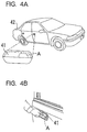
sensor lock 10 described above. Figure 4 shows an
example of applying the sensor lock 10. Figure 4(a)
shows an example where a sensor lock 10 of the type shown
in Figure 1 is used for the doors and trunk of an
automobile.
-
In Figure 4(a), there is no keyhole in the doors and
trunk of the car. Instead, the sensor lock 10 is
installed in the door on the driver's side. The door
handle 41 has the sensor unit A of the sensor lock 10.
The sensor unit A is installed on the inside surface of
the door handle 41 at the position where the index finger
is normally placed when a person pulls the door knob
towards himself, Figure 4(b). The matching circuit B,
the control circuit C, and latching solenoid D, all of
the type shown in Figure 1, are installed inside the door.
-
The trunk lid 42 has a door handle (not shown) for
opening and closing the trunk. A sensor A is installed
on the back side of this handle also. The trunk lid 42
is so constructed that it can be opened by pulling the
trunk handle towards the person who is opening the trunk.
At the time when the doors and trunk are locked, the pin
22 (see Figure 1) of the sensor lock 10 is inside the
hole 23 on the door handle 41 and the trunk handle,
restricting the movement of these parts. The door handle
and the trunk lid handle are thus immobilized and their
locking mechanisms cannot be unlocked, and the door and
trunk remain closed. When a person with a registered
fingerprint presses the sensor 100 of the door or the
trunk with the appropriate finger, the linkage between
the pin 22 and the hole 23 of that sensor get disengaged,
releasing the restriction on the movement of the handle.
So, if the registered person pulls the handle, it moves
and the door or trunk gets unlocked, making it possible
for it be opened.
-
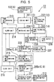
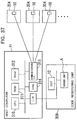
Figure 5 is a functional block diagram of the sensor
lock 10 used in Example 1. The sensor lock 10 has a
sensor 100 (sensor unit A), a coding unit 201 connected
to the sensor 100, a registration and renewal unit 202
connected to the coding unit, and a code record unit 203
that is connected to the registration and renewal unit
202.
-
The coding unit 201 performs some of the function of
the DSP 12 of Figure 1. It prepares a fingerprint code
from the fingerprint pattern detected by the sensor 100.
The code registration and renewal unit 202 also performs
some of the function of DSP 12 of Figure 1. It receives
the fingerprint code form the coding unit 201 and stores
(renews) it in the record unit 203. The code record unit
203 corresponds to the EEPROM 14 of Figure 1 and it
maintains the fingerprint codes stored by the code
registration and renewal unit 202 as the registered
fingerprint codes. The sensor lock 10 is equipped also
with a matching unit 204 which is connected to the coding
unit 201, the access limit determination unit 206 which
is connected to the matching unit 204, the actuator
driving units 205a and 205b and the access limit record
unit 207, all of which are connected to the access limit
determination unit 206, the time judging unit 213 which
is connected to the coding unit 201 and the matching unit
204, an alarm unit 214 which is connected to the matching
unit 204 and the access limit determination unit 206, and
a clock 216 which is connected to the time judging unit
213.
-
Here, the time judging unit 213 maintains the
current time data, on the basis of the clock signals
supplied by the clock 216. The unit 213 receives a
signal from the coding unit 201 when a fingerprint code
has been prepared by coding unit 201, and provides the
time of arrival of the code to the matching unit 204.
-
The clock 216 is a clock generating circuit that
provides clock signals to the time judging unit 213. The
matching unit 204 performs some of the function of the
DSP 12 of Figure 1. Upon receiving the fingerprint code
from the coding unit 201, the matching unit 204 reads out
the registered fingerprint codes from the code recording
unit 203 to determine whether there is any match between
the offered fingerprint code and a registered fingerprint
code. Here, if the matching unit 204 determines that
there is a match, it outputs specific information about
the matched fingerprint code (specific information about
the owner of the fingerprint), a signal for unlocking the
door or trunk (a "Yes" signal) and the arrival time of
the code obtained from the time judging unit 213, to the
access limit determination unit 206. On the other hand,
when there is no match for the offered fingerprint code,
the matching unit 204 sends out specific information
about the code (code-specific information) and a signal
to prevent the unlocking of the door or trunk (a "No"
signal), to both the access limit determination unit 206
and the alarm unit 214.
-
The access limit record unit 207 is, preferably, a
semiconductor memory device. It maintains the access
control data about the door and trunk derived from the
specific information about the fingerprint code. Here,
the access control data are data specifying access
control specific to the owner of each registered
fingerprint code. For example, it can be data about the
time interval during which an enrolled person can use the
car (permitted time period data).
-
The access limit determination unit 206 can consist
of a digital processor (DSP, CPU, etc.) or electronic
circuit. When it receives the code-specific information,
a "Yes" signal and arrival time of the code, all from the
matching unit 204, the access limit determination unit
206 reads out the access control data corresponding to
the code-specific information received, from the access
limit record unit 207 and determines whether to provide
access through the door or trunk, on the basis of the
access control data. The access control unit 206 also
determines whether the arrival time of the fingerprint
code is within the permitted time period, if the access
control data includes data on the permitted time period.
-
The access limit determination unit 206 sends out a
"No" signal and the code arrival time to the actuator
unit 205b and the alarm unit 214 if it judges that access
is to be denied (for instance when the code arrival time
is outside the permitted time interval). On the other
hand, if it judges that access can be permitted (if the
code arrival time is within the permitted time interval,
for instance) it outputs the code-specific information, a
"Yes" signal and the code arrival time to the actuator
unit 205a.
-
With the help of the above-described access limit
determination unit 206, the unlocking of the door or
trunk (the use of the car) can be controlled in relation
to specific information about the fingerprint owner, even
when there is a match of the fingerprint code. This
feature is very useful when one car is to be shared by a
number of persons and the permitted time interval for use
of the car is strictly regulated, even though only an
authorized person can use a car. When there is no
access control data corresponding to the code-specific
information in the access limit record unit 207, the
access limit determination unit 206 provides the code-specific
information about the code that came from the
matching unit 204, a "Yes" signal, and the code arrival
time to the actuator unit 205a. Otherwise it sends a
"No" signal that came from the matching unit 204 and the
code arrival time to the actuator driving unit 205b and a
"No" signal to the alarm unit 214.
-
The actuator units 205a and 205b correspond to the
control circuit C and latching solenoid D of Figure 1.
The actuator unit 205a, upon receiving the code specific
information and a "Yes" signal from the access limit
determination unit 206, removes the restriction on the
movement of the door handle 41 or the trunk handle
(unlocks the door or trunk), making it possible to open
the door or the trunk manually. On the other hand, the
actuator driving unit 205b, upon receiving a "No" signal
from the access limit determination unit 206, restricts
the movement of the door handle 41 or the trunk handle
(locks them). Then the door or trunk can be locked.
-
The alarm unit 214 is comprised of, for instance, a
buzzer, LED, display panel, etc. Upon receiving a "No"
signal from the matching unit 204 or the access limit
determination unit 206, it outputs an alarm sound from
the buzzer, turns on the LED, or displays a warning
message on the display panel (warning display). The
warning display unit can be set up so that it displays
warnings when there is not enough power available to
operate the sensor lock, there is insufficient memory
capacity in the code record unit 203, the sensor 100 is
not properly pressed, when there is some problem in the
sensor lock 10 itself, etc.
-
In addition to these, the sensor lock 10 is provided
with an unauthorized code writing unit 208 which is
connected to the matching unit 204 and code record unit
203, and a code output unit 209 which is connected to the
code record unit 203. The unauthorized code writing
unit 208 consists of, for instance, a memory controller.
This writing unit 208 receives the offered fingerprint
code from the matching unit 204 when the latter sends out
a "No" signal to the access limit determination unit 206,
and writes it in a specific memory area of the code
record unit 203.
-
The code output unit 209 consists of a display
device and a printer. When externally instructed, it
outputs the fingerprint codes recorded in the specific
area of the code recording unit 203. The unauthorized
code writing unit 208 and the output unit 209 enable the
recording and storing of fingerprint codes, other than
those of owners of registered fingerprints, who press the
sensor 100, and outputting these when needed.
-
Therefore, using the fingerprint code outputted by
the code output unit 209, the owner of the unauthorized
fingerprint can be identified. In other words, a person
who tries to open the door or trunk of the car without
authorization can be identified. This can become a
deterrent for unauthorized users. The fingerprint codes
recorded in the specific area of the code record unit 203
are erased after a certain time period or after they are
output.
-
The sensor lock 10 is provided with a time judging
unit 215 which is connected to the actuator driving units
206a and 205b, the alarm unit 214, and the clock unit 216.
This time judging unit 215 can be made up of, for
instance, a timer, etc. When the actuator 205a unlocks
the door or trunk, the time judging unit 215 receives the
corresponding signal and the code arrival time from the
actuator unit 205a and starts counting the time interval
using the signals received from the clock unit 216.
After counting a certain time interval, the time judging
unit 215 sends out a "No" signal to the alarm unit 214
and the time data (the code arrival time plus the counted
time) and a "No" signal to actuator 205b.
-
On receiving these signals, the alarm unit 214
displays the warning described above and the actuator
driving unit 205b locks the door or trunk. In this
manner, the door or trunk gets automatically locked after
the lapse of a certain amount of time after it is
unlocked.
-
The sensor lock 10 is provided also with an
opening/closing record unit 211 which is connected to the
actuator driving units 205a and 205b and opening/closing
record output unit 212 connected to the record unit 211.
This record unit 211 receives locking and unlocking data,
the code arrival time and code-specific information from
the actuator driving units 205a and 205b whenever they
operate. Thus, whether the door or trunk was locked or
unlocked, the time of the locking or unlocking, and
information about the person (code-specific information)
who does the locking or unlocking are stored in the
opening/closing record unit 211.
-
The opening/closing record output unit 212 outputs
its contents in response to an external command. This
feature makes it possible to find out information about
the use of the sensor lock and the use of the car.
-
In Example 1, only persons whose fingerprints have
been registered can unlock the door or trunk of the car.
Therefore, inability to access the car or trunk due to
loss of the key, forgetting the key inside the car, the
key being with someone else, theft of the key, etc. can
be eliminated. Access to the car or trunk by a person
who has stolen the key or made a counterfeit, etc. can
also be prevented.
-
The sensor unit A is far smaller than optical
fingerprint sensors and therefore can be installed on the
back surface of the door handle, where it is not readily
visible. Thus, the certain psychological resistance
against unlocking a door through offering a fingerprint
for matching can be reduced.
-
In this Example 1, sensor units A are provided
separately for the door and trunk. But, the system can
be set up so that the sensor unit A is provided only on
the door handle 41 and the trunk may be locked and
unlocked simultaneously with the door.
-
In Example 1 discussed above, no key hole was
provided in the door or trunk. However, there can be key
holes on the outside of the door and trunk lid and the
sensor lock 10 can prevent the rotation of the key
inserted in the key hole when it is locked. The rotation
of the key which has been inserted in the keyhole is
permitted only in unlocked state and the lock which works
by means of the door or a trunk locking mechanism is
opened accordingly.
〈Example 2〉
-
Figure 6 illustrates Example 2 of Application Mode 1.
Figure 6(a) is a case where the concerned object E of
Figure 1 is for example a door of a building, or a gate.
It shows the outside view of an entrance door 45 on which
the sensor lock 10 has been installed. In Figure 6(a),
the door 45 is provided with a latch bolt 46 and a rotary
shaft 47 that moves the latch bolt 46 inside the door 45,
and a lock equipped with a dead bolt 50. The lock is
basically the same as a conventional lock. In other
words, the outer knob 48 is fixed co-axially on the
rotary shaft 47 and this outer knob 48 has a lever 49
that extends along a direction generally perpendicular to
the shaft 47.
-
The lever 49 is held in a more or less horizontal
initial position by a spring kept in the lock, unless
an external force is applied. The latch bolt 46 sticks
out of the door 45 when the lever 49 is in the initial
position. On the other hand, when the lever 49 turns in
the clockwise or anti-clockwise direction, the latch bolt
46 withdraws into the door 45 in step with the rotation
of the rotary shaft 47 caused by the turning of the outer
knob 48.
-
A sensor A of the type shown in Figure 1 is
installed at the base of the lever 49. The sensor A is
positioned in a such a manner that when a person holds
the lever 49 and extends the thumb, the inner side of the
thumb comes into contact with the sensor (see Figure
6(b)). So, when the door 45 is to be unlocked, the
sensor unit A is naturally pressed by the thumb. A
matching circuit B, control circuit C, and latching
solenoid D of the type shown in Figure 1 are installed
inside the lock. When the door 45 is locked, the pin 22
of the latching solenoid D is engaged with a hole 23 made
on the rotary shaft 47, making the lever 48 immobile at
its initial position. This makes the latching bolt 46
inoperable by the rotary shaft 47 and, like the dead bolt
50, fixed in place to lock the door.
-
When the sensor A is pressed with the appropriate
finger, when the door 45 is in the locked condition, the
matching circuit B outputs a "Yes" signal and the control
circuit C disengages the pin 22 from the hole 23. This
in turn permits the turning of the lever 49, withdrawing
the latch bolt 46 into the door and unlocking the door 45.
In this case, if the dead bolt 50 is sticking out of the
door 45, this also is withdrawn into the door like the
latch bolt 46. The door can now be opened by pulling the
lever 49 outward (or inward).
-
For locking the door 45 from outside, the sensor A
can be pressed by a finger other than one having a
registered fingerprint which, in this case, is any finger
other than the thumb of the right hand. In this example,
the locking by the dead bolt 50 is possible only from the
inner side of the door 45.
-
The sensor lock of Example 2 can be made very small,
because the pressure-based fingerprint sensor 100 is used
for detection of only the fingerprint. Thus, the sensor
unit can be attached to the lever 49 of the outer knob 48
so that it is grasped in a natural way.
-
In this Example 2 also, the system can be set up so
that if there is no match of the fingerprint, the
detected unauthorized fingerprint code can be stored for
some time and unauthorized attempts to open the door can
be deterred.
-
In this example, the latching hole 23 is on the
rotary shaft 47 and the pin 22 enters this hole to
restrict the movement. Instead, the hole 23 can be made
on the latch bolt 46 so that the pin 22 is engaged in it
when the door 45 is locked. In that case, the latch bolt
46 will be extended from the door 45 when it is engaged.
〈Example 3〉
-
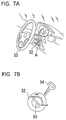
Figure 7 explains Example 3 of Application Node 1 of
the invention. This is a case where a sensor lock 10 of
the type shown in Figure 1 is used to lock a steering
wheel of a car. Figure 7(a) shows the parts around the
steering wheel and Figure 7(b) the ignition switch 52.
-
In Figure 7(a), the ignition switch 52 which may be
operated by the key 54 of the car, is shown installed on
the right side of the steering shaft cover. When the key
54 is inserted in the ignition switch 52 and turned
counter-clockwise to the "Lock" position (Figure 7(b)),
the steering wheel 53 is locked. The structure of the
steering wheel lock is not much different from
conventional locks of this type.
-
A sensor unit A of the type shown in Figure 1 is
installed near the ignition switch 52, and the matching
circuit B, control circuit C and latching solenoid D are
installed inside the steering shaft cover. The pin 22 of
the latching solenoid D restricts turning of the key 54
in the ignition switch 52 when the steering wheel is
locked (when the slot of the key hole of 53 is in aligned
with the "Lock" position).
-
When the steering wheel is thus locked, if the key
54 is inserted in the ignition switch 52 and a person
with a registered fingerprint presses the sensor unit A
with an appropriate finger, the pin 22 of the latch
solenoid D releases ignition switch 52. This permits key
54 to be turned in the clock-wise direction which
releases the steering wheel.
-
According to example 3, the steering wheel cannot be
released with the key 54 alone. This prevents
unauthorized unlocking of the steering wheel using a
stolen or counterfeit key, thereby preventing car theft.
-
Moreover, unless the steering wheel lock is unlocked,
the key 54 cannot turn the ignition switch to the "Start"
position, which means that the starter motor of the car
cannot be operated and the engine cannot be started.
Therefore, the above-described sensor lock 10 functions
as the starter switch of the car also. Here, the system
can be set up so that one more round of fingerprint
matching is required before the key 54 can turn the
ignition switch 52 from the "Off" position to the "Start"
position.
-
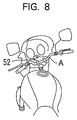
In this Example 3, we have explained a case where
the present invention is used to lock the steering wheel
of a car. But the same invention embodiment can be used
for locking the handle of a motorcycle, a motorbike, a
ship, an aircraft, etc. Figure 8 depicts a part of a
motorbike provided with a handle lock of the type
described above. Because the sensor lock 10 is small, it
can be installed near the ignition switch 52 of the
motorbike and it has little affect on the layout of other
devices.
-
In this example 3, we have shown the set up where a
steering wheel or handle lock itself is operated with a
key, as in conventional locks. But the handle or
steering wheel 53 can be locked or unlocked without using
a key 54 if the pin 22 directly restricts rotary movement
of the steering shaft and the sensor lock 10 locks or
unlocks the steering wheel directly without a key 45,
which may be preferable. Such an arrangement is useful,
for instance, when the key 54 is lost, and the car is to
be moved after unlocking the steering wheel.
〈Example 4〉
-
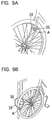
Example 4 is a case where a sensor lock 10 of the
type shown in Figure 4 is used in a bicycle lock. Figure
9(a) and Figure 9(b) show locks 55 and 58 where sensor
locks are used.
-
Figure 9(a) shows a case where the lock 55 is
attached to the front fork of the bicycle. This lock 55
has more or less the same structure as a conventional
bicycle lock. Inside the lock 55 there is a spring that
pushes on the lock bar 56. When the bicycle is unlocked,
this spring is in the compressed state because the lock
bar 56 is pushed into the lock 55. When it is locked,
the pressure on the spring is released and the lock bar
56 is pushed out of the lock 55. The lock 55 is
installed on the front fork in a such a manner that the
lock bar 56 will be between the spokes of the wheel when
it is pushed out of the lock and the bicycle is locked by
restricting the rotation of the wheel.
-
The sensor lock 10 (only the sensor unit A is shown
here) is inside the lock, and it functions like a
conventional key to keep the lock bar 56 inside the lock.
When the bicycle is unlocked, the pin 22 of the latching
solenoid D is engaged with a hole 23 in the lock bar 56
to keep it inside the lock 55. When the sensor unit A,
which is installed on the outer surface of the lock 55,
is pressed with a matching finger, the pin 22 gets
disengaged from the hole 23 and the lock bar is pushed
out of the lock by the spring. In this manner, the lock
55 locks and unlocks the bicycle.
-
Figure 9(b) shows a "chain key" type lock 58 for a
bicycle. One end of the chain 59 has a projection and
the other end has a hole, and the lock is engaged when
the projection is coupled with the hole. The sensor lock
10 of Figure 1 (only the sensor unit A is shown here)
locks these two parts together.
-
At the time of locking, the pin 22 of the latching
solenoid D gets engaged in the hole 23 (not shown) which
are set up in such a way that the projection and the hole
at the two ends of the chain would be coupled together,
locking the chain. This makes the lock 58 form a
continuous ring. As the wheel and an object like an
electrical pole, guard rail, pier, fence post, etc. are
typically included inside this ring, the bicycle is
locked.
-
On the other hand, when the sensor unit A installed
on the outside of the lock 58 is pressed by a matching
finger, the pin 22 disengages from the hole 23 unlocks
the lock 58. Then, by pulling the two ends of the chain
59 apart, the projection comes out of the hole and the
lock 58 assumes the form of a straight chain.
-
In Example 4, since the sensor lock 10 is small in
size, it can be attached to the bicycle lock. Also,
because the sensor lock 10 is insensitive to the various
environmental conditions mentioned above compared to
conventional fingerprint sensors, it can reliably lock
and unlock the bicycle locks 55 and 58 on bicycles which
are normally kept outdoors. This is an advantage that is
not available with conventional fingerprint sensors of
the prior art.
-
In Example 4, a conventional key is not needed for
locking and unlocking the bicycle locks 55 or 58. Thus,
the problem of locking or unlocking the bicycle without
the key which may be lost, misplaced or stolen can be
eliminated.
〈Example 5〉
-
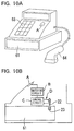
Example 5 is a case where a sensor lock 10 of the
type shown in Figure 1 is used in a cash drawer of a cash
register. Conventionally, an ordinary key alone, or a
key and a secret code number or ID number of a user of
the register, is used for locking and unlocking the cash
drawer of the register. In this case, however, there is
a risk of the cash drawer being opened by an unauthorized
person if the key and/or the ID number of a user are
stolen.
-
Figure 10 shows a register in which a sensor lock 10
is used. At the lower part of the register there is a
drawer type cash box 61 in which the cash is kept (as
shown in Figure 10(a)). This cash drawer 61 is normally
kept locked. It is set up so that when it is unlocked
the drawer sticks out half way.
-
The sensor lock 10 is used as a key to open this
cash drawer 61. The sensor unit A is installed on the
front surface of the register as shown in Figure 10(b),
and the matching circuit B, control circuit C and
latching solenoid D are installed inside the register.
When the cash box 61 is in the locked condition, the pin
22 of the latching solenoid D is engaged with a hole 23
in the cash drawer 61, preventing the drawer from
springing open. Now, if the sensor unit A is pressed by
a matching finger, the pin 22 disengages from the hole 23,
permitting the drawer 61 to spring open. To lock the
cash drawer 61, it is first pushed into the cash register,
and the sensor unit A is pressed with a non-registered
finger.
-
In the cash register used in this example, whenever
the cash drawer 61 is opened using the sensor lock 10,
the fingerprint data and the time are recorded, for
instance, in the RAM of the matching circuit B or in a
memory device (such as a hard disk, magnetic disk, etc.)
installed in the register, and becomes a part of the
"history of unlocking data" of the cash box 61. The
fingerprint data stored in this manner can be the
fingerprint pattern sensed by the sensor unit A or the
fingerprint code obtained by the matching circuit B.
-
In Example 5, since a sensor lock 10 is used for
locking and unlocking the cash drawer 61, unauthorized
opening of the cash box does not occur, such as can
happen with conventional cash registers when the key,
code number of the register, or ID number of a user is
stolen.
-
Moreover, every time the cash drawer 61 is opened
using the sensor lock 10, the history of unlocking data
is recorded. So, the time and identity of the person who
opened the drawer are recorded accurately. Unlike a code
or ID number, a fingerprint cannot be stolen or forged.
Thus, the cash drawer 61 cannot be opened by an
impersonator. Therefore, the data recording the history
of unlocking of the cash drawer contains only data about
authorized opening of the cash drawer. It furthermore
acts as a deterrent to a person with a registered
fingerprint stealing cash from the cash drawer.
-
In the cash register shown in Figure 9, the cash
drawer 61 does not have a conventional lock. It can,
however, have a lock like in a conventional cash register,
and it can be set up so that the sensor lock 10 restricts
the rotation of the key in the lock when the cash drawer
is locked and permits the key inserted in the lock to
rotate and unlock the cash drawer 61 only when there is a
match of the fingerprint codes.
-
In the above example, additional conditions for
unlocking can also be imposed to allow opening of the
drawer, such as inputting a suitable code number through
the input keys 63, providing a bar code (encoding the ID
of an authorized user) which is read by a bar code reader
64, etc.
〈Example 6〉
-
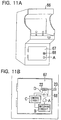
We shall now explain Example 6 where the sensor lock
10 of the type shown in Figure 1 is used in an enclosure
66 of a game machine. Fig. 11(a) shows an enclosure 66 of
a game machine, in which the sensor lock 10 is used.
Inside this enclosure 66 are housed the base board of a
video game, a cash box for storing the money charged for
playing the game, etc. A door 67 is provided at the
front bottom of the enclosure 66. The person who
maintains the game machine collects the game charges,
changes the base board, carries out maintenance, etc.
through this door 67.
-
The door 67 has a sensor lock 10 to prevent theft of
cash and the base board. The sensor unit A is installed
on the outer surface of the door 67 as shown in Fig.
11(b) and the matching circuit B, control circuit C, and
latching solenoid D are installed in the door 67. The
pin 22 of the latching solenoid D engages the hole 23 in
the enclosure 66, locking the door 67. On the other hand,
when the sensor unit A is pressed with the appropriate
finger, the pin 22 disengages the hole 23, unlocking the
door 67. Therefore, the door 67 can be opened by pulling
the handle 68.
-
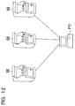
When the sensor unit A is pressed, the fingerprint
data and the time are recorded on the hard disk (not
shown) kept in the enclosure 66, as unlocking history
data. A number of enclosures 66 are connected to a PC
(computer) through a communication cable as shown in
Figure 12 and the unlocking history data recorded in the
hard disk are transferred to the PC where they are
subject to unitary control.
-
In the case of Example 6, the door 67 of the
enclosure 66 cannot be opened unless a finger with a
registered fingerprint is used. Therefore, the stealing
of cash or the game board from the enclosure by using a
stolen key or a counterfeit key is prevented.
-
Traditionally, the cash is collected from the
enclosures 66 and the game machines are maintained by
employees who turn in statements on perhaps a daily basis.
This method of maintaining and servicing the machines
creates the possibility of theft by and employee turning
in a false statement. In Example 6, however, because the
unlocking history data of each container 66 are pooled
and maintained accurately by the PC, false declarations
are readily detected and the theft of cash from the cash
box, etc. can be discovered and prevented.
〈Example 7〉
-
Example 7 is a case where a sensor lock 10 of the
type shown in Figure 1 is used in a coin locker.
Conventionally, a lock with an ordinary key is used for
locking coin lockers. Therefore, if the user of the
locker loses the key, he or she has to report the loss to
the manager of the locker facility, and the locker has to
be unlocked with a master key.
-
Figure 13 shows a coin locker 70 where sensor lock
10 is used. The sensor lock 10 (only the sensor unit A is
shown in the Figure) is installed on the outer frame of
the coin locker 70. This sensor lock locks and unlocks,
i.e., opens and closes, the door 71 through the same
mechanism as explained in Example 6 (see Figure 11(b)).
-
The coin locker 70 can be operated by inserting a
coin into the slot 72. While the locker is in use, a
display device like the LED 73 is on, indicating that it
is in use. A certain time limit is assigned for the use
of the locker by a person with a registered fingerprint.
After this time limit, the LED 73 of the coin locker 70
blinks, for instance, indicating that the permitted time
limit has expired.
-
Let us suppose that the user of locker 70 has
forgotten the location of his coin locker. The user may
press the sensor unit A of any one of the coin lockers.
If it happens to be his coin locker, the LED 73 would
blink at a fast rate (for instance) indicating that it is
the user's locker.
-
In this example, a conventional key is not required
for unlocking the coin locker 70. Thus, any
inconvenience arising from the loss of the key can be
eliminated. Occasionally, there are instances of coin
lockers being used for crimes. Arms, fake passports,
even dead bodies, etc. have in fact been found in coin
lockers, where the permitted period of use had expired.
The coin locker 70, however, requires fingerprint
registration as a pre-condition for its use. Thus, it
can prevent the use of coin lockers for crime or even
reduce crimes of the type described above.
〈Example 8〉
-
Example 8 is a case where the sensor lock 10 of the
type shown in Figure 1 is used for cash transaction
devices such as an automatic teller machine (ATM), cash
dispensers, automatic money changers, etc. Such cash
transaction devices have a built-in cash box where the
cash received from the customer, or to be given to the
customer, is stored. They further have a door for paying
in or dispensing the cash and this door is conventionally
locked with a lock and key. This arrangement has the
risk of cash theft by unauthorized persons opening the
door using stolen or counterfeit keys.
-
Figure 14 shows the ATM 74 which is a cash
transaction device of Example 8. The cash box 75 is
built into the ATM 74. The door 76 is installed on the
front of the ATM 74 for providing access to the cash box
75. This door has a sensor lock 10 of the type shown in
Figure 1 which locks and unlocks the door 76 through the
same mechanism, as explained in Example 6. As in
Example 6, whenever the sensor unit A is pressed with a
finger, the unlocking history is recorded on a hard disk,
etc. (not shown).
-
In Example 8, because a sensor lock 10 is used for
locking and unlocking the door 76, any inconvenience
caused by the theft of the key, etc. is avoided. Also,
stealing of cash by persons with registered fingerprints
can be detected and deterred because the door unlocking
history data are recorded. Unlike with the use of secret
code numbers, an unauthorized person cannot impersonate
an authorized user.
-
The sensor lock 10 of the type shown in Figure 14
may also be used on the cash collection door 76a of a
public telephone (as shown in Figure 15).
〈Example 9〉
-
Example 9 teaches the use of a sensor lock 10 of the
type shown in Figure 1 in a post office or letter drop
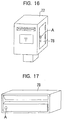
box. Figure 16 shows the drop box (pillar box) 77 of
Example 9. The drop box has a door 78 for removing the
deposited mail. The door 78 has a sensor lock 10 (only
the sensor unit A is shown) having the same structure as
in Example 6, for locking and unlocking the door 78.
-
Here, as in Example 9, a pressure-based fingerprint
sensor 100 is used in the sensor unit A. Therefore, even
if the sensor lock 10 is used on the door of the drop box
which is usually located outdoors, the detection accuracy
of the fingerprint pattern is not adversely affected by
environmental conditions mentioned above as experienced
by ordinary fingerprint sensors of the prior art.
-
The sensor lock 10 may be installed on a domestic
letter box 79 as shown in Figure 17. Mail is closely
related to an individual's privacy. In recent years,
with the increased use of credit cards, information about
the use of credit cards, stock transaction records, etc.
are also being sent through the mail, and the importance
of mail has increased. Previously, individual letter
boxes that can be opened by input of secret code numbers
had been suggested. But in that case, there is the risk
of the mail being stolen by others, or the information
contained in the mail becoming known to others who come
to know the code number. Particularly in the letter
boxes of apartments, the secret code numbers are often
not changed when there is a change of the tenant, and the
letter boxes could be opened by the previous tenant. But
if a sensor lock 10 used, this type of inconvenience in
the use of letter boxes and other private temporary mail
storage containers can be eliminated.
〈Example 10〉
-
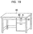
Example 10 is the case where a sensor lock 10 of the
type shown in Figure 1 is used for drawers of desks,
credenzas, filing cabinets, etc. Figure 18 shows an
office desk 80 in which a sensor lock 10 is used. This
office desk 80 has the sensor lock 10 (only the sensor
unit A is shown) having about the same structure as the
one used in Example 5 (see Figure 10(b)) installed in it
for locking the drawer 81.
-
In Example 10, an ordinary key is not used to lock
the drawer 81. Therefore, any inconvenience caused by a
loss of the key does not arise. Also, in offices where a
number of identical looking desks are used, there is
often confusion about which key belongs to which desk.
Such confusion also does not arise when the system of
Example 10 is used. The sensor lock 10 can also be used
in lockers installed in offices. In that case also,
since a number of similar lockers are used, the same
advantages can be realized.
-
The sensor unit A can be installed on the back
surface of the handle 82 of the drawer 81 (as shown in
Figure 19), which has the same effect as the sensor unit
A installed on the back side of the door handle 41 in
Example 1.
〈Example 11〉
-
Example 11 is the case where the sensor lock 10 of
the type shown in Figure 1 is applied in a bank locker
(safe deposit box). Figure 20 shows the bank locker 84 of
Example 11. Here, the bank locker has a sensor lock 10
(only the sensor unit A is shown) with the same structure
as in Example 2 (see Figure 6(b)). In bank locker 84,
whenever the sensor unit A is pressed, data on history of
unlocking is recorded as in Example 6.
-
In Example 11 also there is the advantage of not
having to use an ordinary key, as in the other examples.
The bank locker 84 can be opened only by the person whose
fingerprint has been registered. Thus, upon opening the
locker, there is no need to verify the identify of the
person, by checking the seal, etc. This makes it
unnecessary for the bank worker, etc. to be present at
the opening of the locker 84, and completely automatic 24
hour operation of the bank locker is possible. Also,
since the unlocking history data are recorded, one can
always know accurately when the locker 84 was opened and
by whom.
〈Example 12〉
-
Example 12 deals with a case where the sensor lock
10 of the type shown in Figure 1 is used in luggage, such
as a suit case, attache case, handbag, travel bag, etc.
Figure 21 shows an attache case having a sensor lock 10
(only the sensor unit A is shown). As the sensor lock 10
is small in size, it can be used for the attache case 85.
-
Also, because of its small size it can be used in
padlocks and even in various types of notebooks 86, like
diaries, notebooks, memo pads, registers, account books,
etc. as shown in Figure 23. In notebooks such as diaries
that will be used for a long period of time, the status
of the fingerprint that will be used to unlock the
notebook must be updated. For example, if the owner of
the registered fingerprint is a growing child, the
registered fingerprint may be updated periodically and
the information may be used as a part of the record of
the child's growth. Otherwise, the risk is that the
changing fingerprint characteristic of the growing child
will unintentionally lead to his inability to open the
diary.
〈Example 13〉
-
Example 13 is the case in which a sensor lock 10 of
the type shown in Figure 1 is used in an automatic
vending machine. Figure 24 shows an automatic vending
machine 87 which has the sensor lock 10 (only the sensor
unit A is shown). The vending machine 87 has an openable
front 88 for stocking the vended goods and the small
change, etc. The sensor lock 10 having about the same
structure as in Example 6 is used for locking and
unlocking this openable front 88. The use of this sensor
lock as previously explained detects, deters, and thus
helps prevent problems like theft of goods or cash from
the machine that can occur when a conventional lock and
key are used. In Figure 24, the sensor unit A is shown
mounted on the side of the dispenser 88. It can of
course be mounted on the front or any other convenient
location instead.
〈Example 14〉
-
Example 14 is the case where the sensor lock 10 of
the type shown in Figure 1 is used in a strong box (safe).
Figure 25 depicts the safe 89 which has the sensor lock
10 (only the sensor unit A is shown). Locking and
unlocking of the door 90 of the safe 89 is done through
the sensor lock 10 installed on the frame of the door of
the safe 89. This sensor lock has about the same
structure as in Example 6.
-
The sensor lock 10 is small in size. Therefore, it
can be installed in this manner on the frame of the door.
Also, because there is no need for running power cables
for the sensor lock 10 from the door frame to the door,
any failure due to a failed power cable is avoided.
-
A record of the registered fingerprint codes is kept
in the EEPROM 14 (see Figure 1) of the matching circuit B
of the sensor lock 10. The matching circuit B outputs
the "Yes" signal in this case only when all the
registered fingerprint codes are matched within a certain
time interval. Because more than one fingerprint code
has to be detected, and all the registered fingerprints
have to match within a certain time period for opening
the safe, theft by less than all of the persons who have
registered fingerprints can be prevented. The security
level of the safe is thus greater than with prior art
arrangements.
〈Example 15〉
-
Example 15 is the case where the sensor lock 10 is
used on firearms, such as a pistol, rifle, revolver, etc.
Figure 26 shows a gun 91 in which the sensor lock 10
(only the sensor unit A is shown) is installed, for
locking and unlocking the safety catch of the gun.
Because the sensor lock 10 is small in size, it can be
installed even on a gun. This permits the use of the gun
only by the owner of the registered fingerprint.
Therefore, the stealing and misuse of the gun 91 and
violation of any governmental firearms act can be
prevented.
〈Example 16〉
-
Example 16 is a case where a sensor lock 10 of the
type shown in Figure 1 is used in a pin ball machine.
Figure 27 shows a pin ball machine 92 in which a sensor
lock 10 is used. The pin ball play area 93 of the
machine 92 is covered with a glass door 94, which permits
the player to see the play area 93, at the same time
preventing the balls from jumping out of the area. The
glass door 94 is kept locked using a lock installed on
the outer frame of the pin ball table 92 when it is in
use, to prevent the player from tampering with the game.
-
The lock of the door 94 is embedded in the outer
frame of the pin ball machine 92. The lock has a key
hole 95 for inserting the key 95a. When the key 95a is
inserted in the hole 95 and turned, the lock is released.
The sensor lock 10 of the type shown in Figure 1 is
installed within this outer frame, and the sensor unit A
is installed near the key hole 95.
-
The pin 22 of the latching solenoid D of the sensor
lock 10 engages a certain coupling part (not shown)
installed in the lock when the door 94 is locked,
preventing the rotation of the key 95a when it is
inserted in the key hole. The pin 22 disengages and the
restriction on the rotation of the key 95a is removed
only when the sensor unit A is pressed by the appropriate
finger. Thus, a person with a registered fingerprint may
turn the key 95a to unlock the lock and pull the handle
96 to open the door.
-
As in Example 6, whenever the sensor unit A is
pressed, the unlocking data are recorded. When there is
a number of pin ball machines 92, the unlocking data of
all the machines are maintained by a host computer (not
shown).
-
In Example 16, a person with a registered
fingerprint alone can open the door 94 using his finger
and the key 95a. Therefore, unauthorized opening of the
door 94, using a stolen or counterfeit key, for improper
mechanical adjustment of its inner workings or for
unauthorized setting of the ROM inside the pin ball
machine 92, etc. can be prevented.
-
Also, because the unlocking data are recorded every
time the sensor unit A is pressed, the record of when and
by whom the door 94 was opened can be examined in the
event of any suspicious activity. This prevents
unauthorized actions by employees of the pin ball game
Centre. The feature of easy identification of the person
who opens the door 94 is a special feature not available
with the prior art devices.
-
In Example 16, the latching solenoid D of the sensor
lock 10 controls the rotation of the key 95a inserted in
the key hole 95. But instead, it can be set up so that
the latching solenoid D directly opens or locks the door,
in which case the conventional lock and key become
unnecessary.
-
The above-described locking system for the door 94
can be used for all types of pin ball processing
equipment used in pin ball game centers, such as the ball
dispensing machine, ball counting machine, for the supply
route of the balls, etc.
-
Figure 28 shows a pin ball counting machine that
uses the sensor lock 10. An electronic circuit that
counts the pin balls, and the return route of the pin
balls, is installed inside this counting machine. The
door 97 is to be opened for maintaining this counting
machine. This door has a sensor lock 10 for locking it
and can be opened only by the owner of a registered
fingerprint. Whenever the door 97 is thus opened, a
record of who opened the door, and when, is made. This
arrangement can prevent unauthorized opening of the door
97, by stealing the key for instance, for tampering with
the electronic controls in the counting machine (changing
the set number of pin balls, for instance), stealing pin
balls from the pin ball recovery route, etc.
-
Supply and recovery routes for pin balls are
provided at pin ball centers. Such routes are normally
placed in containers, housings, inside walls, etc., and
sensor locks 10 can be used for locking the access doors
of such containers. This arrangement can prevent the
theft of pin balls from these pin ball supply/recovery
routes.
-
In the Examples 7 to 14 described earlier, the
sensor lock 10 can also be used as described in Example
16, that is, using sensor lock 10 to lock and unlock a
conventional lock.
[Application Mode 2]
-
Figure 29 is a diagram of the sensor lock 10a used
in Application Mode 2 of the present invention. Because
it has many features in common with the sensor lock 10
used in Application Mode 1, we shall explain here only
the features that are different from the sensor lock 10.
-
Some of the constituent elements of the sensor lock
10a used in Application Mode 2 are housed in a single
container which acts as the controller for the pin 22 of
the latching solenoid D, as shown in Figure 29. The
controller in Figure 29 can, for instance, be in the form
of a card K in which the sensor unit A and the matching
circuit B are embedded. The control circuit C and the
latching solenoid D are attached to the concerned object
E which is to be locked or unlocked. Thus, the matching
circuit B is physically separated from the control
circuit C. The matching circuit B has a data
transmission unit 24 and the control circuit C has a data
receiving unit 25. "Yes" and "No" signals are
transmitted between these two units.
-
Here, any mode of data transmission can be employed
between the transmission unit 24 and the receiving unit
25. In other words, these units may be physically
connected through cables, or the transmission can be
through conventional non-contact data transmission
methods like optical, wireless, magnetic coupling, static
electricity based systems, etc. In other words, the card
K can be of any type. It can be a non-contact type card
in which optical or magnetic coupling is used, a card
that can be read by a card reader, or a PC compatible
contact type card with a PCM/CIA card interface.
-
There can be a matching circuit on the data
receiving side of the controller also, as shown in Figure
30. In that case, it can be set up so that the data
transmission side, i.e., the card K, carries out only the
preparation of the fingerprint codes while the processing
of fingerprint code registration and matching are done on
the data receiving side. In this case, the EEPROM 14 of
the card K need not be present. The system can also be
set up in a way that the card K carries out only the
fingerprint code preparation and matching processes and
not the fingerprint registration. In other words, the
flash memory 11 does not have the fingerprint code
registration program.
-
The system can also be set up in such a way that the
card K (controller) carries out the fingerprint code
creation and fingerprint code registration, and the
matching is done on the data receiving side. In that
case, the EEPROM 14 and HDD 15 need not be present on the
data receiving side. If the data receiving side alone
stores the registered fingerprint codes and the matching
is done by the card K (controller), the registered
fingerprint codes can be transmitted from the data
receiving side to the data transmitting side. In that
case, the data transmission unit 24 should also have the
ability to receive data and the data receiving unit 25
should have the ability to transmit data. The sensor
unit A can be on the card K (controller) or otherwise.
-
The sensor unit A installed on the card K
(controller) can have a structure where the pressure
sheet 102 (see Fig. 2(a)) of the sensor 100 is always
exposed. The card K can also of course have a cover to
protect at least the surface of the pressure sheet 102 of
the sensor. This cover can be a lid that can be rotated
in relation to the surface of pressure sheet 102 or it
can be of a type that is installed parallel to the
pressure sheet 102 and slides over it to cover it. This
cover for the sensor unit A is applicable for all the
examples of the Application Mode 2 described below.
-
In this Application Mode 2, the number of
constituent elements of the system attached to the
concerned object E can be reduced. Thus, if the
concerned object E is small and it is difficult to attach
the sensor lock 10 to it, the sensor lock 10a can still
be applied. Moreover, even if the card K is lost or
stolen, it cannot be used by any person other than the
owner of the registered fingerprint. Thus, it does not
have the inconveniences associated with conventional keys.
Another advantage is that it is possible to lock and
unlock more than one concerned object E using one card K
(see Figures 31 and 32). This means that a separate card
K does not need to be prepared for each concerned object
E.
-
The sensor lock 10a may be used in place of the
sensor lock 10 in all the examples of the Application
Mode 1.
〈Example 17〉
-
An example of the Application Mode 2 is given below.
In this Example 17, a sensor lock 10a of the Application
Mode 2 is used as a key of a car. In Figure 33, the door
lock of the car 300 is unlocked by an unlocking code
generated by the key 301 (which is the controller). The
key 301 has the components of the card K shown in Figure
29 (only the sensor unit A is shown in Figure 33), and a
conversion circuit (not shown) which converts the "Yes"
signal received from the matching circuit into the
unlocking code.
-
Because of this arrangement, when the sensor unit A
is pressed by the appropriate finger, the unlocking code
is transmitted by the key 301 and received by a receiving
unit installed on the car 300, unlocking the door lock of
the car. In this Example 17, the elements of the card K
and the addition of a conversion circuit to the key 310
are improvements over the prior art. Alternatively, a
sensor lock 10a with the structure shown in Figure 29 may
be used in the car 300.
-
In Example 17, because of the structure of card K
used and the conversion circuit that is added to it to
form the key 301, only a registered fingerprint owner can
unlock the door lock. So, unauthorized opening of the
lock by the use of lost keys or stolen keys can be
prevented. The unlocking code of the door lock is
provided to the user by the manufacturer of the car.
Thus, by slightly modifying the key 301, the types of
inconveniences like unauthorized opening of the door lock
described above can be eliminated. This locking system
can be used for locking the trunk of the car 300 also.
〈Example 18〉
-
Example 18 is a case where a sensor lock 10a of the
type shown in Figure 29 is used in a door, as shown in
Figure 34(a). The data receiving unit 25 is installed
on the outer surface of the door. The setup on the door
side is the same as in Example 2 (Figure 6). Thus, we
shall omit the explanation of this setup here. As shown
in Figure 34(b), the card K can be used by inserting it
into the connector 303 installed on the outer surface of
the door.
〈Example 19〉
-
Example 19 is a case where a sensor lock 10a of the
type shown in Figure 29 is used for an enclosure 66 of a
game machine (Figure 35). We shall omit the explanation
of Example 19 here because the setup is the same as in
Example 6 (Figure 11) except for the elements of the
sensor lock 10a. However, as shown in Figure 31, the
system can be set up so that one card K can be used to
open the doors 67 of more than one enclosure 66.
-
Here, however, if the locks installed on the door 67
of each enclosure 66 is to be opened with a different
unlocking signal, then the card K is to be so designed
that it can output all these unlocking signals so that
all the doors 67 can be individually opened.
〈Example 20〉
-
Example 20 is a case where a sensor lock 10 of the
type shown in Figure 1 is used in the doors of rooms of a
lodging facility, like a hotel or an inn. Figure 36(a)
shows the appearance of the outside of a door 304 which
is the entrance to a room. The door 304 has the sensor
lock 10 (only the sensor unit A is shown here) which has
the same structure as in Example 2. Besides this, the
door 304 has a slot 305 in which the card 306, with the
recorded fingerprint code of the customer, is to be
inserted. A card reader (not shown) is installed in the
slot 305 for reading the fingerprint code from the
inserted card 306.
-
The fingerprint code read out by the card reader is
maintained for a certain duration as a registered
fingerprint code in the EEPROM 14 (see Figure 1) of the
matching circuit B. Therefore, if the customer presses
the sensor unit A using the same finger as of the
registered fingerprint code during this period, the door
304 will be unlocked and can be opened. After that, when
a certain amount of time has elapsed, the door 304 is
locked automatically and the fingerprint code is erased
from the EEPROM 14. In that case, the customer has to
again insert the card 306 in the slot 305 and press the
sensor unit A for entering the room.
-
The card 306 is, for instance, a disposable card
made of paper, with magnetic stripes provided on one side
to record the fingerprint code. The recording of the
fingerprint code on the card 306 can be done by a card
writer 307 placed at the front desk of the lodging
facility. The card writer 307 can consist of, for
example, a sensor unit A of the type shown in Figure 1, a
DSP 12 that executes the fingerprint print code
preparation program and the fingerprint code registering
program, and code writing unit 308 that writes the code
on the magnetic stripes of the card 306, as shown in
Figure 36(b).
-
When the sensor unit A of the card writer 307 is
pressed by a finger, the fingerprint pattern is detected
by the sensor unit A, and the DSP 12 prepares the
fingerprint code using this fingerprint pattern. This
fingerprint code is then written on the card 306 by the
card writing unit 308. At the time of checking in, the
customer receives the card 306 on which his or her
fingerprint code is recorded. This card is used to unlock
the door of the room through the sensor lock 10.
-
In Example 20, the door 304 is unlocked using the
disposable card 306 and the sensor lock 10. Thus, the
front desk of the hotel, etc. need not concern itself
with the whereabouts of the key of each room. Also,
since the card 306 can be used only by the person whose
fingerprint is registered, the door 304 can never be
unlocked using a stolen or lost card. In addition to
this, even if the customer loses the card, the reissue of
the card is very easy.
-
In this example, the fingerprint data are not handed
over to the owner of the lodging facility. Thus, the
psychological resistance of the guest against the use of
fingerprints for opening the door can be overcome. The
card 306 can also be a punched card.
-
The sensor lock 10 in the door 304 of each hotel
room can be connected to a host computer H via
communication lines and the fingerprint code of the
customer can be registered on the hard disk 314 of the
host computer H through a code registering unit 309, as
shown in Figure 37.
-
In this case, the customer registers the fingerprint,
at the time of check-in, on the hard disk 314 of the
computer H through the code registering unit 309 placed
at the front desk. Then, to unlock his room he just
presses the sensor unit A on the door.
〈Example 21〉
-
We shall now explain Example 21. When the concerned
object E which is to be locked or unlocked using the
above-described sensor lock 10 or 10a belongs to the
person with a registered fingerprint, in principle the
fingerprint code registered in the matching circuit B
need not be changed. On the other hand, if the
authorized user of the concerned object E changes quite
frequently, requiring the registered fingerprint code to
be changed frequently, (such as with the letter box or
door of a rented apartment or house, a car door, the cash
drawer of a cash register, the door of a hotel room,
etc.) the registered fingerprint code in the matching
device B has to be erased and a new fingerprint code
registered. If the sensor lock 10 or 10a has a feature
that can easily register a new fingerprint code, there is
the risk of an unauthorized person registering his or her
fingerprint code and unlocking the concerned object E.
-
Figure-38 shows a row of letter boxes 79, each using
a sensor lock 10, in an apartment house. Here, the flash
memory 11 (see Figure 1) of the sensor lock 10 (only the
sensor units A are shown) does not have the fingerprint
code registering program 19. Thus, the DSP 12 cannot
register and store the fingerprint codes prepared by it
in the EEPROM 14.
-
For storing the registered fingerprint code in each
EEPROM 14, a code registering device 309 shown in Figure
37 should be connected to the individual sensor lock 10.
The fingerprint code created by pressing the sensor unit
A of the code registering device 309 is then registered
in the EEPROM 14 of the sensor lock 10. When a new
fingerprint code is registered in the EEPROM 14, it
overwrites the existing fingerprint code.
-
Thus, the system is set up so that registering a new
fingerprint is possible only by using the special
fingerprint code registering device 309. Because of this
arrangement, a new fingerprint code cannot be registered
by pressing the sensor unit A of the sensor lock 10 of a
letter box. Unauthorized registration of new
fingerprints can be prevented if the code registering
device 309 is kept with the manager and it is used only
in the presence of the manager. Also, since the old
fingerprint code is automatically erased when a new
fingerprint code is registered, there is no possibility
of the previous tenant being able to open a letter box.
-
Figure 39 shows the door 316 of a car in which a
sensor lock 10 is used. Here also, the DSP 12 of the
sensor lock 10 does not register the fingerprint codes
made by it in the EEPROM 14. Instead, the fingerprint
code is registered by a code registering device 309a.
The code registering device 309a is a non-contact type
card machine in which radio waves or other
electromagnetic waves are used for data transmission.
Its internal structure is about the same as the code
registering device 309 mentioned earlier. Each code
registering device 309a is exclusive for a car. So it
can register fingerprint codes for the sensor lock 10
only of the car to which it belongs.
-
When the sensor unit A of the code registering
device 309a is pressed, the fingerprint code is
transferred from the data transmission unit (not shown)
of the code registering device 309a to the data receiving
unit (also not shown) of the matching circuit B. However,
the code registration device 309a exchanges a secret code
with the sensor lock 10 to verify each other before
transferring the fingerprint code. When the two units
fail to verify, the code registering device 309a does not
transmit a fingerprint code. When the data receiving
unit of the matching circuit B receives the fingerprint
code, it is stored in the EEPROM 14 and becomes a
registered fingerprint code. When a new fingerprint code
is registered in the EEPROM 14, the previously registered
fingerprint code is erased.
-
When the above-described sensor lock 10 and the code
registering device 309a are used, the registration of the
fingerprint code for the sensor lock 10 is done only by
the corresponding code registering unit 309a. Thus, as
long as others are not permitted to use the code
registration unit 309a, there is no possibility of the
registered fingerprint code being overwritten without
authorization. Also, since the sensor lock 10 by itself
cannot register fingerprint codes, any inconvenience or
security risk arising from unauthorized registration of
fingerprint codes does not arise.
〈Example 22〉
-
Example 22 is a case where the sensor lock 10 is
used in a centralized locking system in an apartment
house (block of flats). Figure 40(a) shows the external
appearance of the centralized locking control device 310.
In this Figure, the centralized locking control unit 310
has a sensor unit A and an inputting key pad 311. Such a
control unit 310 can be installed, for instance, at the
entrance of an apartment house. Figure 40(b) shows the
system configuration of this centralized locking control
system.
-
In Figure 40(b), the locking control system 310 is
shown to be connected through communication lines to the
sensor locks 10 installed on the entrance doors 316 of
each apartment. These sensor locks 10 on the doors of
the apartments have about the same structure as in
Example 2. When a resident of an apartment inputs a code
number (the room number of the resident, for instance)
through the input key pad 311 to the centralized locking
control system 310, the CPU 312 carries out the processes
described below by executing stored software programs
maintained in the ROM 313.
-
In short, the CPU 312 uses the code number inputted
to open the communication line between with the sensor
lock 10 installed on the entrance door 316 of the
apartment corresponding to the code number. If the
sensor unit A is then pressed with a finger other than
the one having the registered fingerprint, the CPU 312
prepares the fingerprint code and sends it to the sensor
lock 10 through the communication line. When the
fingerprint code reaches the sensor lock 10, the matching
circuit B of the sensor lock 10 carries out the matching.
In this case, the entrance door 316 is locked because the
fingerprint code does not match with a registered code.
On the other hand, if the fingerprint codes match, the
lock of the entrance door
316 is unlocked.
-
Because of the arrangement described above, if the
resident of the apartment remembers that he forgot to
lock his entrance door 316, after reaching the entrance
of the building, he can lock his door 316 while he is
standing at the entrance of the building. He can also
unlock the entrance door 316 of his room from that
location, if he so desires.
〈Example 23〉
-
Example 23 is a case where a sensor lock 10 of the
type shown in Figure 1 is placed on the entrance door of
a room with restricted entry, such as a room in which
important or classified documents are stored, secret
meetings are held, etc. Figure 41 is the system diagram
of the entrance door 323 of this Example 23. In this
Figure the CPU 317 executes the stored software programs
maintained in ROM 319, by loading them into the RAM 318.
The hard disk 320 maintains a photographic data base 320a,
an ID code database 320b and a fingerprint code database
320c, of persons who are authorized to enter the room.
-
Figure 42 is the flow chart of the software for
operating the system shown in Figure 41. This program
starts when an ID document, a company ID card issued to
an employee for instance, of a person who is authorized
to enter is input into an image reader. The image reader
322 reads out image data from the photograph on the ID
card (Step S101).
-
In the next step, the CPU 317 compares the
photographic image data acquired in Step S101 with the
photographic image data stored in the database 320a (Step
S102) and determines whether there is a match (Step S103).
If there is a match (S103; Yes), the program moves on to
Step S104. Otherwise (S103; No) the program moves to
Step S112.
-
If it proceeds to Step S104, the CPU 317 reads out
the current time from the clock 317a and determines
whether it is in the time period of 9 AM to 5 PM. If it
is within this time zone (S104; Yes), the program moves
to Step S113. Otherwise (S104; No) the program moves to
S105. If the program moves to Step S105, the CPU 317
demands the input of an ID code from the person through
the input unit 321, and obtains the ID code.
-
In the next step, the CPU 317 compares the ID code
obtained in S105 with the ID codes stored in the ID code
database 320b (Step S105) to determine whether there is a
match (Step S106). If there is a match (S106; Yes), the
program moves to S104. Otherwise (S106; No) the program
proceeds to Step S112.
-
In Step S108, the CPU 317 obtains the current time
from the clock 317a and determines whether it is in the
time zone 5 PM to 10 PM. If the answer is "Yes" (S108;
Yes), the program proceeds to Step S113. Otherwise
(S108; No) it moves to Step S109. In Step S109, the CPU
demands from the person the input of a fingerprint
through the sensor unit A. The fingerprint code is then
prepared from the fingerprint pattern sensed by the
sensor unit A.
-
In the next step, the CPU 317 compares the
fingerprint code obtained in Step S109 with the
fingerprint codes in the fingerprint code database 320c
(Step S110) to determine whether there is a match (Step
S111). If there is a match (S111; Yes), the program
moves to S113. Otherwise (S111; No) the program proceeds
to Step S112.
-
When the program moves to Step S112, the system
concludes that there was no match in the photographic
data, ID code or fingerprint code and gives out an error
display (alarm display) on a display unit (not shown) to
complete the program. In this case, the lock of the
entrance door 323 does not get unlocked.
-
On the other hand, if the program advances to S113,
a "Yes" signal is sent to the control circuit C and, pin
22 of the latching solenoid D gets disengaged, unlocking
the door 323.
-
With the system operating as explained above, the
inlet door 323 gets unlocked to permit authorized persons
to enter the room if the time that entry is sought (the
time at which the image reader starts reading the image)
is within normal working hours (9:00 AM to 5:00 PM) and
the photographic data on the ID card matches the
registered photographic data. Relatively mild entry
conditions are imposed during working hours because other
security personnel at the entry point can also check the
identity of the person seeking entry.
-
On the other hand, if the time that entry is sought
is during 5:00 to 10:00 PM, when the majority of the
employees will be off duty and not at the facility, the
conditions of entry are made stricter. Entry is
permitted only when both the photographic data and the ID
code match.
-
The most stringent conditions of entry are imposed
during the time period of 10:00 PM to 9:00 AM of the
following day, when almost no employee is in the facility.
Entry is permitted only when the photographic data, the
ID code and the fingerprint code, all match. In this
manner, the level of security can be changed by varying
the entry conditions depending on the time that entry is
sought.
[Application Mode 3]
-
Application Mode 3 concerns newly invented switches
in which the pressure-based fingerprint sensor is used.
Figure 43 shows the structure of switch 10b used in this
application mode. The sensor unit A and matching circuit
B of the switch 10b are basically the same as those used
in Application Mode 1. However, the starter switch SW is
connected to the matching circuit B and the object F to
be started (which can be an electrical or electronic
device) is connected to the starter switch SW. The
starter switch SW is turned on when a "Yes" signal is
received from the matching circuit B, starting the object
F. Here, F can be a motor, an actuator (including
solenoids), or electrical products (such as electrical or
electronic devices).
-
When switch 10b of this application mode is used,
only a person with a registered fingerprint can start the
concerned object F. Therefore, unlike with switches that
require a conventional key, any inconvenience like not
being able to start the concerned object F because of
loss or theft of the key does not arise. In the above-described
switch 10b, the sensor unit A and the matching
circuit B can be housed in a card K (controller) as in
Application Mode 2. Variations of the controller (card K)
explained for Application Mode 2 are all applicable as
explained above for the configuration of the card K in
this Application Mode 3.
〈Example 24〉
-
We shall now give some examples of using the
Application Mode 3. Example 24 is a case where a switch
10b of the type shown in Figure 43 is used for starting a
car engine. As shown in Figure 44, a switch 10b (only
the sensor unit A is shown here) is installed, instead of
the ignition switch, on the right hand side of the
steering shaft cover.
-
If the sensor unit A is pressed with an appropriate
finger of a person with a registered fingerprint, the
matching circuit B outputs a "Yes" signal. This signal
turns on the power source switch (not shown) which makes
it possible to supply power to the electrically powered
accessories (radio, cassette player, door mirror, power
window, etc.) of the car.
-
The actuator that shifts the driver's seat backward
or forward and another actuator that changes the
inclination of the back of this seat are installed in the
driver's seat of the car. The central rear view mirror
and the side mirrors are also equipped with actuators
that change their angles. An actuator for changing the
position of the steering wheel is also provided.
-
When the power switch is turned on upon receiving
the "Yes" signal, the processor unit (not shown) that
controls the operation of the actuators, becomes
operational and drives these actuators on the basis of
the positioning data (the angle of the seat back, the
forward-backward position of the seat, the position of
the steering wheel, and angles of the rear view mirror
and side mirrors) of the fingerprint registered person
pre-recorded in the memory unit (not shown). Thus, when
the sensor unit A is pressed by an appropriate finger,
the optimum driving position and settings for other
electrically operated accessories for the fingerprint
registered person is automatically created.
-
After this, a "Yes" signal is given to the starter
switch SW. Upon receiving this "Yes" signal, the starter
switch SW starts the power supply from the battery to the
starter motor (corresponding to the electrical and
electronic devices) of the engine while at the same time
firing the spark plugs at certain time intervals. This
starts the motor, starting the engine.
-
In Example 24, a conventional ignition switch which
uses a key is not provided. Instead, the switch 10b
controls the power supply to the starter motor.
Therefore, the inconvenience of not being able to start
the car because of loss or theft of the key does not
arise.
-
When the system decides that there is a match in the
fingerprint code, the optimum driving position is created
before power is supplied to the starter motor. Driving
position resetting systems have been known for some time,
but in conventional systems the driver had to operate a
switch manually for resetting the optimum driving
position. Sometimes the driver remembers after starting
the car that he had forgotten to press this switch, and
presses the switch after the car has started. In that
case, the position of the driver's seat, angles of the
mirrors, etc. would change while the car is running,
posing some risk to the driver. In some other systems,
pressing any manual controls would be ineffective in
creating any adjustment as operation was disabled when
the ignition was on to prevent any unsafe condition. In
Example 24, the suitable driving position is set before
the engine is started. So, it does not have the problems
associated with the conventional prior art systems.
-
The switch 10b can be used for stopping the engine
also. For example, the system can be so set up that when
the sensor unit A is pressed with a finger other than the
appropriate one, the power switch turns off power supply
to the spark plugs, which stops the engine.
-
The starting and stopping of the engine using the
switch 10b is not limited to cars. For example, it may
be used in motorized bicycles, motorcycles, large sized
vehicles, ships, aircraft, diesel vehicles, etc. The
setting of the optimum driving position and adjustment of
other electrical accessories can be applied in large
sized vehicles, ships, aircraft, etc., also.
〈Example 25〉
-
Example 25 is a case where a switch 10b of the type
shown in Figure 43 is used to operate a garage door
controlled by remote controller 324. As shown in Figure
45, the remote controller 324 has the same structure as
the card K of Figure 29. When the sensor unit A of this
remote controller 324 is suitably pressed, the LED 325,
which acts as the data transmission unit 24, outputs a
"Yes" signal. This "Yes" signal is received by a photo-sensor
unit (not shown) installed on the side of the
shutter 326, and then transmitted to the starter switch
SW.
-
The starter switch SW then turns on the power supply
(an electrical or electronic device not shown) that moves
the garage door vertically. Here, if the garage door 326
is down at or near its lowest position, it moves up (the
garage door opens) and if it is at or near its highest
position, it moves down (the garage door closes).
-
The starter switch SW is so set up that if it
receives a "Yes" signal while the garage door is moving,
it shuts off the power supply to the actuator, stopping
the movement of the garage door.
-
Conventional remote controlled garage doors can be
operated by any one who has the remote control. But in
Example 25, only a person whose fingerprint has been
registered can operate the garage door. So, unauthorized
opening of the garage door using a stolen remote control,
trespassing into the garden or garage that is locked out
by the garage door and the damaging of property placed
there, etc. can be averted.
〈Example 26〉
-
Example 26 is a system in which the above-mentioned
switch 10b and a sensor lock 10 are used in combination.
As shown in Figure 46, the "Yes" signal coming from the
matching circuit B is inputted to the control circuit C
upon which the latching solenoid D unlocks the lock
328 of the door 327. In this case, the "Yes" signal is
inputted to the switch 330 of the air conditioner and the
switch 332 of the light 331, turning on the air
conditioner and the light. The system is set up so that
when the door 327 is locked by the sensor lock 10, the
air conditioner 329 and the light 331, etc. inside the
room are turned off.
-
Therefore, when the person with the registered
fingerprint comes home and presses the sensor unit A on
the door 327 at the entrance, the door is unlocked and
simultaneously the light 331 of the room is turned on and
the air conditioner 329 also starts operation.
Alternatively, the system can be set up so that the
operation of the air conditioner, light, etc. inside the
room can be controlled remotely, by transmitting a
fingerprint code to the switch 10b through a public
communication system like telephone wires, ISDN, etc.
-
The examples explained above under these application
modes are merely examples of various implementations of
the invention. The newly invented locks and switches
that use a pressure-based fingerprint sensor have wide
applicability on objects for which restricted access is
desired.