EP0978040B1 - Memory device - Google Patents
Memory device Download PDFInfo
- Publication number
- EP0978040B1 EP0978040B1 EP97926095A EP97926095A EP0978040B1 EP 0978040 B1 EP0978040 B1 EP 0978040B1 EP 97926095 A EP97926095 A EP 97926095A EP 97926095 A EP97926095 A EP 97926095A EP 0978040 B1 EP0978040 B1 EP 0978040B1
- Authority
- EP
- European Patent Office
- Prior art keywords
- data storage
- relatively fast
- access
- mass
- storage means
- Prior art date
- Legal status (The legal status is an assumption and is not a legal conclusion. Google has not performed a legal analysis and makes no representation as to the accuracy of the status listed.)
- Expired - Lifetime
Links
Images
Classifications
-
- G—PHYSICS
- G06—COMPUTING; CALCULATING OR COUNTING
- G06F—ELECTRIC DIGITAL DATA PROCESSING
- G06F3/00—Input arrangements for transferring data to be processed into a form capable of being handled by the computer; Output arrangements for transferring data from processing unit to output unit, e.g. interface arrangements
- G06F3/06—Digital input from, or digital output to, record carriers, e.g. RAID, emulated record carriers or networked record carriers
- G06F3/0601—Interfaces specially adapted for storage systems
-
- G—PHYSICS
- G06—COMPUTING; CALCULATING OR COUNTING
- G06F—ELECTRIC DIGITAL DATA PROCESSING
- G06F12/00—Accessing, addressing or allocating within memory systems or architectures
- G06F12/02—Addressing or allocation; Relocation
- G06F12/08—Addressing or allocation; Relocation in hierarchically structured memory systems, e.g. virtual memory systems
- G06F12/0802—Addressing of a memory level in which the access to the desired data or data block requires associative addressing means, e.g. caches
- G06F12/0866—Addressing of a memory level in which the access to the desired data or data block requires associative addressing means, e.g. caches for peripheral storage systems, e.g. disk cache
-
- G—PHYSICS
- G06—COMPUTING; CALCULATING OR COUNTING
- G06F—ELECTRIC DIGITAL DATA PROCESSING
- G06F2212/00—Indexing scheme relating to accessing, addressing or allocation within memory systems or architectures
- G06F2212/31—Providing disk cache in a specific location of a storage system
- G06F2212/312—In storage controller
-
- G—PHYSICS
- G06—COMPUTING; CALCULATING OR COUNTING
- G06F—ELECTRIC DIGITAL DATA PROCESSING
- G06F3/00—Input arrangements for transferring data to be processed into a form capable of being handled by the computer; Output arrangements for transferring data from processing unit to output unit, e.g. interface arrangements
- G06F3/06—Digital input from, or digital output to, record carriers, e.g. RAID, emulated record carriers or networked record carriers
- G06F3/0601—Interfaces specially adapted for storage systems
- G06F3/0628—Interfaces specially adapted for storage systems making use of a particular technique
- G06F3/0655—Vertical data movement, i.e. input-output transfer; data movement between one or more hosts and one or more storage devices
- G06F3/0656—Data buffering arrangements
Definitions
- the present invention relates to memory devices. It finds particular application in the field of data storage in computers.
- Non-volatile storage medium is required.
- One common non-volatile storage medium is the magnetic disk drive, another non-volatile storage medium is a solid state disk that emulates magnetic disk drives.
- a cache is usually a volatile memory which stores the most recent data accessed by the host. When power to the memory system is removed the data in the cache is copied to the mass storage device.
- the advantage of a cache is that it enables a large, slow memory to appear as a large, fast memory by adding a small fast memory.
- Cache memory operates under the control of a cache manager which ensures that appropriate data is always accessible in the cache.
- a cache manager which ensures that appropriate data is always accessible in the cache.
- One disadvantage of a cache is that the algorithms used by the cache manager are often very complicated so a cache is usually designed to work with a particular system and requires a large processing overhead.
- a software cache is implemented by the processor of a computer.
- the processor uses the memory of the computer as a cache and it also uses an area of the storage medium in use to store data blocks as they are transferred to and from the cache.
- EP-A-0564699 It is known from EP-A-0564699 to provide a storage system with both a disk drive and a solid state disk to provide bulk storage in the disk drive and fast access memory in the solid state disk.
- a host connected to the system considers the memory provided by the disk drive and solid state disk as entirely separate storage devices accessed via a buffer memory which is partitioned accordingly.
- EP-A-0702305 It is also known from EP-A-0702305 to provide a disk drive with a controller which shuts down the disk drive when memory is idle for a predetermined period of time.
- a non-volatile memory duplicates storage of selected data blocks for rapid access during shut down, the data blocks being selected on the basis of history of the access to the data blocks.
- a data storage arrangement for a host computer or the like having a relatively slow-access mass data storage device connected thereto wherein said data storage arrangement comprises relatively fast-access data storage means consisting, at least in part, of non-volatile memory and controller means connectible to said host computer and to said mass data storage device, selectively to route data between said host computer and either said mass data storage device or said relatively fast-access data storage means.
- the embodiment provides a system that can be inserted into a standard personal computer, or other data processing device, and connected to a standard storage medium such as a magnetic disk.
- the system uses fast non-volatile memory to provide permanent storage of data and it may also incorporate some fast memory to act as a data buffer, thus increasing the performance of the storage medium that is being used.
- the embodiment differs from a software cache in a number of ways. It relates to hardware which can be connected to existing hardware to provide a cache-like function with permanent storage of the information. Since most caches are volatile, the contents of a cache must be generated over a period of time. Thus, the initial access of each data entry in the cache must be to the mass storage device.
- the high speed memory of the present invention is located entirely in the mass storage device: no executable code is required to occupy valuable main memory space.
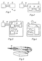
- Figure 1 shows a typical arrangement for a computer system 10 where a host 12 (such as a personal computer) is connected to a memory system 14 by a standard interface 16.
- the standard interface could be such as is conventionally used with a magnetic disk, for example an ATA or an IDE interface).
- the memory system 14 stores data which is accessed by the host 12 via the standard interface 16.
- the memory system 14 shown in Figure 1 is composed of a master unit 18 and a slave unit 20 connected by a standard interface 16. This is shown in Figure 2.
- the slave unit 20 is typically a magnetic disk which serves as the high volume storage area (the mass storage area) for storing information sent by the host 12.
- the memory system 14 provides the same function to the host 12 as would be provided if the slave unit 20 was connected directly to the host 12. That is, the existence of the master-slave arrangement is transparent to the host 12.
- the master unit 18 is a high speed, non-volatile memory system which comprises a controller 22, a first internal interface 24 and a high speed memory 26.
- the first internal interface 24 may be the same as the standard interface 16.
- the master unit 18 forms a portable store which can be connected to any standard magnetic disk and appropriate standard interface 16 to improve access to the magnetic disk.
- the non-volatile memory capacity of the memory system 14 is the sum of the capacities of the master unit 18 and the slave unit 20.
- the function of the controller 22 within the master unit 18 is to ensure that a high proportion of the data sector accesses made by the host 12 are made to the high speed memory 26 rather than the slave unit 20. This provides a higher performance than if the slave unit 20 is always accessed.
- the controller 22 also maintains a lookup table that stores the location of each data sector, for example, whether a data sector is in the high speed memory 26 or in the slave unit 20.
- the controller 22 ensures that a high proportion of the data accesses requested by the host 12 are in the high speed memory 26 by relocating data sectors between the high speed memory 26 and the slave unit 20.
- Sectors written by the host 12 would normally be located in the high speed memory 26: sectors read from the slave unit 20 would normally be simultaneously relocated to high speed memory 26.
- the controller 22 would normally also have access to the host's File Allocation Table (FAT) and could relocate sectors which are part of an active file (a file currently being used). Other techniques used in conventional cache memories could also be applied to the present invention.
- FAT File Allocation Table
- multiple high speed memories 26 may also be connected to a single controller 22.
- the memory system of the present invention differs from a conventional cache memory in that both the high speed memory 26 and the slave unit 20 are non-volatile memories. Data is not temporarily located in the high speed memory 26 as a copy of the data in the slave unit 20, as is the case with a high speed cache. Only one version of each data sector is maintained. The data sector is stored either in the high speed memory 26 or in the slave unit 20. Thus the memory configuration is retained when electrical power is restored.
- One of the characteristics of the present invention is that it is configured as a single device conforming to a mass storage standard and occupying two physical disk slots.
- multiple slave units 20 are connected to a single master unit 18.
- the high speed memory 26 comprises two memories: a non-volatile memory 28 and a volatile memory 30 connected by a second internal interface 32.
- the second internal interface 32 could be identical to the first internal interface 24 or it may conform to a different standard.
- the volatile memory 30 is used as a buffer memory to allow fast write operations.
- the volatile memory 30 is a Static Random Access Memory (SRAM) and the non-volatile memory 28 is a FLASH EPROM. All data sectors stored in the SRAM 30 will be copied to the FLASH EPROM 28 for permanent storage.
- SRAM Static Random Access Memory
- the FLASH EPROM 28 will have some means of ensuring uniform memory usage to avoid excessive wear of the FLASH EPROM cells, this function may be implemented by a high speed memory control unit 34. Since FLASH EPROM 28 has a slow write cycle, the SRAM 30 is used to improve the performance of the master unit 18 for writing data.
- the high speed memory control unit 34 would not need any additional memory, because the memory is used as a buffer for the solid state disk.
- the controller 22 also has the necessary logic to move data from the high speed memory 26 to the slave unit 20 to liberate space in the high speed memory as the free space in the high speed memory 26 diminishes.
- the movement of data between the high speed memory 26 and the slave unit 20 is controlled by the controller 22.
- the present invention is suitable for use with any convenient algorithm.
Description
- Figure 1
- shows a diagram of a computer system;
- Figure 2
- shows a diagram of a master-slave memory system;
- Figure 3
- shows a diagram of a master-slave memory system showing detail of the master unit;
- Figure 4
- shows a diagram of a high speed memory; and
- Figure 5
- shows a diagram of an implementation of the present invention.
Claims (15)
- Apparatus (18) for connection between a computer system (12) and a relatively slow-access mass data storage device (20), the apparatus comprising a controller means (22) connectible to said host computer and to said mass data storage device; and
a relatively fast-access data storage means (26) connected to the controller means;
wherein the controller means is selectively operable to route data between said host computer, said mass data storage device and said relatively fast-access data storage means;
said controller means comprising;
means for determining whether a data sector is to be stored in the mass data storage device or the relatively fast-access data storage means such that only one version of the data sector is maintained, and means to relocate data between said relatively fast access data storage means and said mass data storage device to ensure that a greater proportion of data sector accesses made by the computer system are to the relatively fast access data storage means rather than the mass data storage device. - Apparatus as claimed in claim 1 wherein said relatively fast-access data storage means further includes relatively fast-access volatile memory (30) to act as a data buffer, thereby increasing the performance of the storage medium that is being used.
- Apparatus as claimed in claim 2 wherein said volatile memory comprises Static Random Access Memory.
- Apparatus as claimed in claim 1 wherein said relatively fast-access data storage means comprises FLASH erasable programmable read-only memory.
- Apparatus as claimed in claim 4 wherein said relatively fast-access data storage means includes means (34) adapted to equalise usage of said erasable programmable read-only memory.
- Apparatus as claimed in claim 4 wherein said relatively fast-access data storage means includes static random-access memory (30) to improve the speed of access of said host computer or the like for writing data.
- Apparatus as claimed in claim 1 wherein said controller means includes storage means to store information on whether a data sector is currently in said relatively fast-access data storage means or in the mass data storage device.
- Apparatus as claimed in claim 1 wherein said means to relocate data is operable to ensure that the data sector which was accessed least recently is moved from the relatively fast access data storage means to the mass storage area first.
- Apparatus as claimed in claim 1 wherein said means to relocate is operable to ensure that the data sector which is accessed least frequently is moved from the relatively fast access data storage means to the mass storage area first.
- Apparatus according to any one of the preceding claims comprising an input and an output interface having a common format whereby it may be interposed between said host computer and said mass data storage device.
- A system comprising a computer system (12) in combination with said apparatus in accordance with any one of the preceding claims.
- A method of operating apparatus (18) providing connection between a computer system (12) and a relatively slow-access mass data storage device (20), the apparatus comprising a controller means (22) connectible to said host computer and to said mass data storage device; and
a relatively fast-access data storage means (26) connected to the controller means;
wherein the method comprises operating the controller means to selectively route data between said host computer, said mass data storage device and said relatively fast-access data storage means;
said controller means determining whether a data sector is to be stored in the mass data storage device or the relatively fast-access data storage means such that only one version of the data sector is maintained, and relocating data between said relatively fast access data storage means and said mass data storage device to ensure that a greater proportion of data sector accesses made by the computer system are to the relatively fast access data storage means rather than the mass data storage device. - A method as claimed in claim 12 wherein said controller stores information on whether a data sector is currently in said relatively fast-access data storage means or in the mass data storage device.
- A method as claimed in claim 12 wherein said relocating step ensures that the data sector which was accessed least recently is moved from the relatively fast access data storage means to the mass storage area first.
- A method as claimed in claim 12 wherein said relocating step ensures that the data sector which is accessed least frequently is moved from the relatively fast access data storage means to the mass storage area first.
Applications Claiming Priority (3)
| Application Number | Priority Date | Filing Date | Title |
|---|---|---|---|
| GBGB9613088.5A GB9613088D0 (en) | 1996-06-21 | 1996-06-21 | Memory device |
| GB9613088 | 1996-06-21 | ||
| PCT/GB1997/001532 WO1997050035A1 (en) | 1996-06-21 | 1997-06-09 | Memory device |
Publications (2)
| Publication Number | Publication Date |
|---|---|
| EP0978040A1 EP0978040A1 (en) | 2000-02-09 |
| EP0978040B1 true EP0978040B1 (en) | 2004-05-06 |
Family
ID=10795708
Family Applications (1)
| Application Number | Title | Priority Date | Filing Date |
|---|---|---|---|
| EP97926095A Expired - Lifetime EP0978040B1 (en) | 1996-06-21 | 1997-06-09 | Memory device |
Country Status (3)
| Country | Link |
|---|---|
| EP (1) | EP0978040B1 (en) |
| GB (1) | GB9613088D0 (en) |
| WO (1) | WO1997050035A1 (en) |
Cited By (16)
| Publication number | Priority date | Publication date | Assignee | Title |
|---|---|---|---|---|
| US7634585B2 (en) | 2005-11-04 | 2009-12-15 | Sandisk Corporation | In-line cache using nonvolatile memory between host and disk device |
| US7634624B2 (en) | 2001-09-28 | 2009-12-15 | Micron Technology, Inc. | Memory system for data storage and retrieval |
| US7681057B2 (en) | 2001-09-28 | 2010-03-16 | Lexar Media, Inc. | Power management of non-volatile memory systems |
| US7725628B1 (en) | 2004-04-20 | 2010-05-25 | Lexar Media, Inc. | Direct secondary device interface by a host |
| US7734862B2 (en) | 2000-07-21 | 2010-06-08 | Lexar Media, Inc. | Block management for mass storage |
| US7743290B2 (en) | 2004-08-27 | 2010-06-22 | Lexar Media, Inc. | Status of overall health of nonvolatile memory |
| US7774576B2 (en) | 1995-07-31 | 2010-08-10 | Lexar Media, Inc. | Direct logical block addressing flash memory mass storage architecture |
| US7865659B2 (en) | 2004-04-30 | 2011-01-04 | Micron Technology, Inc. | Removable storage device |
| US7908426B2 (en) | 1995-07-31 | 2011-03-15 | Lexar Media, Inc. | Moving sectors within a block of information in a flash memory mass storage architecture |
| US7944762B2 (en) | 2001-09-28 | 2011-05-17 | Micron Technology, Inc. | Non-volatile memory control |
| US7949822B2 (en) | 2004-08-27 | 2011-05-24 | Micron Technology, Inc. | Storage capacity status |
| US8078797B2 (en) | 1995-07-31 | 2011-12-13 | Micron Technology, Inc. | Increasing the memory performance of flash memory devices by writing sectors simultaneously to multiple flash memory devices |
| US8166488B2 (en) | 2002-02-22 | 2012-04-24 | Micron Technology, Inc. | Methods of directly accessing a mass storage data device |
| US8171203B2 (en) | 1995-07-31 | 2012-05-01 | Micron Technology, Inc. | Faster write operations to nonvolatile memory using FSInfo sector manipulation |
| US8386695B2 (en) | 2001-09-28 | 2013-02-26 | Micron Technology, Inc. | Methods and apparatus for writing data to non-volatile memory |
| CN103699336A (en) * | 2013-12-03 | 2014-04-02 | 中国科学院计算技术研究所 | Method and system for distributing and reestablishing data of magnetic disc array |
Families Citing this family (8)
| Publication number | Priority date | Publication date | Assignee | Title |
|---|---|---|---|---|
| US7127549B2 (en) | 2004-02-04 | 2006-10-24 | Sandisk Corporation | Disk acceleration using first and second storage devices |
| US7136973B2 (en) | 2004-02-04 | 2006-11-14 | Sandisk Corporation | Dual media storage device |
| US9104315B2 (en) | 2005-02-04 | 2015-08-11 | Sandisk Technologies Inc. | Systems and methods for a mass data storage system having a file-based interface to a host and a non-file-based interface to secondary storage |
| US20060184717A1 (en) * | 2005-02-17 | 2006-08-17 | Intel Corporation | Integrated circuit capable of flash memory storage management |
| US7543179B2 (en) | 2005-03-21 | 2009-06-02 | Intel Corporation | Error management topologies |
| US7412619B2 (en) | 2005-03-21 | 2008-08-12 | Intel Corporation | Integrated circuit capable of error management |
| US7899987B2 (en) | 2007-05-15 | 2011-03-01 | Sandisk Il Ltd. | File storage in a computer system with diverse storage media |
| EP2098458A1 (en) * | 2008-03-03 | 2009-09-09 | Superfos a/s | Container comprising an inner lining, a method of applying such a lining to a container and use of a peel able coating as an inner lining in a container |
Family Cites Families (6)
| Publication number | Priority date | Publication date | Assignee | Title |
|---|---|---|---|---|
| GB2256735B (en) * | 1991-06-12 | 1995-06-21 | Intel Corp | Non-volatile disk cache |
| JP2582487B2 (en) * | 1991-07-12 | 1997-02-19 | インターナショナル・ビジネス・マシーンズ・コーポレイション | External storage system using semiconductor memory and control method thereof |
| US5420998A (en) * | 1992-04-10 | 1995-05-30 | Fujitsu Limited | Dual memory disk drive |
| JPH06236241A (en) * | 1993-02-09 | 1994-08-23 | Sharp Corp | Hard disk device using flash memory |
| JPH06314177A (en) * | 1993-04-28 | 1994-11-08 | Toshiba Corp | Magnetic disk device and access method |
| JPH0883148A (en) * | 1994-09-13 | 1996-03-26 | Nec Corp | Magnetic disk device |
-
1996
- 1996-06-21 GB GBGB9613088.5A patent/GB9613088D0/en active Pending
-
1997
- 1997-06-09 WO PCT/GB1997/001532 patent/WO1997050035A1/en active IP Right Grant
- 1997-06-09 EP EP97926095A patent/EP0978040B1/en not_active Expired - Lifetime
Cited By (37)
| Publication number | Priority date | Publication date | Assignee | Title |
|---|---|---|---|---|
| US8171203B2 (en) | 1995-07-31 | 2012-05-01 | Micron Technology, Inc. | Faster write operations to nonvolatile memory using FSInfo sector manipulation |
| US8397019B2 (en) | 1995-07-31 | 2013-03-12 | Micron Technology, Inc. | Memory for accessing multiple sectors of information substantially concurrently |
| US8554985B2 (en) | 1995-07-31 | 2013-10-08 | Micron Technology, Inc. | Memory block identified by group of logical block addresses, storage device with movable sectors, and methods |
| US7774576B2 (en) | 1995-07-31 | 2010-08-10 | Lexar Media, Inc. | Direct logical block addressing flash memory mass storage architecture |
| US9026721B2 (en) | 1995-07-31 | 2015-05-05 | Micron Technology, Inc. | Managing defective areas of memory |
| US7908426B2 (en) | 1995-07-31 | 2011-03-15 | Lexar Media, Inc. | Moving sectors within a block of information in a flash memory mass storage architecture |
| US8078797B2 (en) | 1995-07-31 | 2011-12-13 | Micron Technology, Inc. | Increasing the memory performance of flash memory devices by writing sectors simultaneously to multiple flash memory devices |
| US8032694B2 (en) | 1995-07-31 | 2011-10-04 | Micron Technology, Inc. | Direct logical block addressing flash memory mass storage architecture |
| US8793430B2 (en) | 1995-07-31 | 2014-07-29 | Micron Technology, Inc. | Electronic system having memory with a physical block having a sector storing data and indicating a move status of another sector of the physical block |
| US8019932B2 (en) | 2000-07-21 | 2011-09-13 | Micron Technology, Inc. | Block management for mass storage |
| US8250294B2 (en) | 2000-07-21 | 2012-08-21 | Micron Technology, Inc. | Block management for mass storage |
| US7734862B2 (en) | 2000-07-21 | 2010-06-08 | Lexar Media, Inc. | Block management for mass storage |
| US7944762B2 (en) | 2001-09-28 | 2011-05-17 | Micron Technology, Inc. | Non-volatile memory control |
| US8386695B2 (en) | 2001-09-28 | 2013-02-26 | Micron Technology, Inc. | Methods and apparatus for writing data to non-volatile memory |
| US7917709B2 (en) | 2001-09-28 | 2011-03-29 | Lexar Media, Inc. | Memory system for data storage and retrieval |
| US8694722B2 (en) | 2001-09-28 | 2014-04-08 | Micron Technology, Inc. | Memory systems |
| US8135925B2 (en) | 2001-09-28 | 2012-03-13 | Micron Technology, Inc. | Methods of operating a memory system |
| US9032134B2 (en) | 2001-09-28 | 2015-05-12 | Micron Technology, Inc. | Methods of operating a memory system that include outputting a data pattern from a sector allocation table to a host if a logical sector is indicated as being erased |
| US9489301B2 (en) | 2001-09-28 | 2016-11-08 | Micron Technology, Inc. | Memory systems |
| US7681057B2 (en) | 2001-09-28 | 2010-03-16 | Lexar Media, Inc. | Power management of non-volatile memory systems |
| US8208322B2 (en) | 2001-09-28 | 2012-06-26 | Micron Technology, Inc. | Non-volatile memory control |
| US7634624B2 (en) | 2001-09-28 | 2009-12-15 | Micron Technology, Inc. | Memory system for data storage and retrieval |
| US8166488B2 (en) | 2002-02-22 | 2012-04-24 | Micron Technology, Inc. | Methods of directly accessing a mass storage data device |
| US9213606B2 (en) | 2002-02-22 | 2015-12-15 | Micron Technology, Inc. | Image rescue |
| US8090886B2 (en) | 2004-04-20 | 2012-01-03 | Micron Technology, Inc. | Direct secondary device interface by a host |
| US7725628B1 (en) | 2004-04-20 | 2010-05-25 | Lexar Media, Inc. | Direct secondary device interface by a host |
| US8316165B2 (en) | 2004-04-20 | 2012-11-20 | Micron Technology, Inc. | Direct secondary device interface by a host |
| US8151041B2 (en) | 2004-04-30 | 2012-04-03 | Micron Technology, Inc. | Removable storage device |
| US8612671B2 (en) | 2004-04-30 | 2013-12-17 | Micron Technology, Inc. | Removable devices |
| US7865659B2 (en) | 2004-04-30 | 2011-01-04 | Micron Technology, Inc. | Removable storage device |
| US9576154B2 (en) | 2004-04-30 | 2017-02-21 | Micron Technology, Inc. | Methods of operating storage systems including using a key to determine whether a password can be changed |
| US10049207B2 (en) | 2004-04-30 | 2018-08-14 | Micron Technology, Inc. | Methods of operating storage systems including encrypting a key salt |
| US7949822B2 (en) | 2004-08-27 | 2011-05-24 | Micron Technology, Inc. | Storage capacity status |
| US7743290B2 (en) | 2004-08-27 | 2010-06-22 | Lexar Media, Inc. | Status of overall health of nonvolatile memory |
| US8296545B2 (en) | 2004-08-27 | 2012-10-23 | Micron Technology, Inc. | Storage capacity status |
| US7634585B2 (en) | 2005-11-04 | 2009-12-15 | Sandisk Corporation | In-line cache using nonvolatile memory between host and disk device |
| CN103699336A (en) * | 2013-12-03 | 2014-04-02 | 中国科学院计算技术研究所 | Method and system for distributing and reestablishing data of magnetic disc array |
Also Published As
| Publication number | Publication date |
|---|---|
| WO1997050035A1 (en) | 1997-12-31 |
| EP0978040A1 (en) | 2000-02-09 |
| GB9613088D0 (en) | 1996-08-28 |
Similar Documents
| Publication | Publication Date | Title |
|---|---|---|
| EP0978040B1 (en) | Memory device | |
| CN107632939B (en) | Mapping table for storage device | |
| KR100771519B1 (en) | Memory system including flash memory and merge method of thereof | |
| KR100684887B1 (en) | Data storing device including flash memory and merge method of thereof | |
| KR100684942B1 (en) | Adaptive flash memory control device with multiple mapping schemes and flash memory system havintg the same | |
| KR100568115B1 (en) | Incremental merge method and memory system using the same | |
| US10776153B2 (en) | Information processing device and system capable of preventing loss of user data | |
| Park et al. | A high performance controller for NAND flash-based solid state disk (NSSD) | |
| JP4155463B2 (en) | System having flash management system using only sequential writing and method thereof | |
| US20140337566A1 (en) | Solid state memory (ssm), computer system including an ssm, and method of operating an ssm | |
| US20100023676A1 (en) | Solid state storage system for data merging and method of controlling the same according to both in-place method and out-of-place method | |
| US5983319A (en) | Information recording and reproduction apparatus and a method of data caching including read-ahead capability | |
| KR20090102192A (en) | Memory system and data storing method thereof | |
| KR20100065786A (en) | Cache synchronization method and system for fast power-off | |
| US8433847B2 (en) | Memory drive that can be operated like optical disk drive and method for virtualizing memory drive as optical disk drive | |
| KR20130024271A (en) | Storage system including hdd and nvm | |
| KR100963009B1 (en) | File management system and method | |
| CN111984441B (en) | Instant power-off recovery processing method and device and computer readable storage medium | |
| KR20100035408A (en) | Solid state disk device and random data processing method thereof | |
| KR102589609B1 (en) | Snapshot management in partitioned storage | |
| EP2381354A2 (en) | Data recording device | |
| JPH01303547A (en) | Control system for information memory | |
| KR100982440B1 (en) | System for managing data in single flash memory | |
| JPH05258585A (en) | Filing device | |
| KR20100055374A (en) | File management system and method |
Legal Events
| Date | Code | Title | Description |
|---|---|---|---|
| PUAI | Public reference made under article 153(3) epc to a published international application that has entered the european phase |
Free format text: ORIGINAL CODE: 0009012 |
|
| 17P | Request for examination filed |
Effective date: 19990104 |
|
| AK | Designated contracting states |
Kind code of ref document: A1 Designated state(s): GB |
|
| RAP1 | Party data changed (applicant data changed or rights of an application transferred) |
Owner name: MEMQUEST, INC |
|
| 17Q | First examination report despatched |
Effective date: 20020130 |
|
| GRAP | Despatch of communication of intention to grant a patent |
Free format text: ORIGINAL CODE: EPIDOSNIGR1 |
|
| RAP1 | Party data changed (applicant data changed or rights of an application transferred) |
Owner name: LEXAR MEDIA, INC. |
|
| GRAS | Grant fee paid |
Free format text: ORIGINAL CODE: EPIDOSNIGR3 |
|
| GRAA | (expected) grant |
Free format text: ORIGINAL CODE: 0009210 |
|
| AK | Designated contracting states |
Kind code of ref document: B1 Designated state(s): GB |
|
| REG | Reference to a national code |
Ref country code: GB Ref legal event code: FG4D |
|
| PLBE | No opposition filed within time limit |
Free format text: ORIGINAL CODE: 0009261 |
|
| STAA | Information on the status of an ep patent application or granted ep patent |
Free format text: STATUS: NO OPPOSITION FILED WITHIN TIME LIMIT |
|
| 26N | No opposition filed |
Effective date: 20050208 |
|
| PGFP | Annual fee paid to national office [announced via postgrant information from national office to epo] |
Ref country code: GB Payment date: 20150603 Year of fee payment: 19 |
|
| GBPC | Gb: european patent ceased through non-payment of renewal fee |
Effective date: 20160609 |
|
| PG25 | Lapsed in a contracting state [announced via postgrant information from national office to epo] |
Ref country code: GB Free format text: LAPSE BECAUSE OF NON-PAYMENT OF DUE FEES Effective date: 20160609 |