EP0981262A2 - Implant - Google Patents
Implant Download PDFInfo
- Publication number
- EP0981262A2 EP0981262A2 EP98121614A EP98121614A EP0981262A2 EP 0981262 A2 EP0981262 A2 EP 0981262A2 EP 98121614 A EP98121614 A EP 98121614A EP 98121614 A EP98121614 A EP 98121614A EP 0981262 A2 EP0981262 A2 EP 0981262A2
- Authority
- EP
- European Patent Office
- Prior art keywords
- housing
- energy source
- electrical energy
- implant
- potential
- Prior art date
- Legal status (The legal status is an assumption and is not a legal conclusion. Google has not performed a legal analysis and makes no representation as to the accuracy of the status listed.)
- Withdrawn
Links
- 239000007943 implant Substances 0.000 title claims abstract description 60
- 239000000523 sample Substances 0.000 claims abstract description 28
- 239000003792 electrolyte Substances 0.000 claims description 10
- 239000000446 fuel Substances 0.000 claims description 3
- 238000000034 method Methods 0.000 abstract description 11
- 230000008569 process Effects 0.000 abstract description 10
- 238000004904 shortening Methods 0.000 abstract 1
- 238000005259 measurement Methods 0.000 description 14
- 230000006870 function Effects 0.000 description 7
- 239000012212 insulator Substances 0.000 description 6
- WHXSMMKQMYFTQS-UHFFFAOYSA-N Lithium Chemical compound [Li] WHXSMMKQMYFTQS-UHFFFAOYSA-N 0.000 description 4
- 229910052744 lithium Inorganic materials 0.000 description 4
- 239000005518 polymer electrolyte Substances 0.000 description 4
- 239000011701 zinc Substances 0.000 description 4
- 239000003990 capacitor Substances 0.000 description 3
- 238000009413 insulation Methods 0.000 description 3
- 239000007788 liquid Substances 0.000 description 3
- 238000004519 manufacturing process Methods 0.000 description 3
- 229910052751 metal Inorganic materials 0.000 description 3
- 239000002184 metal Substances 0.000 description 3
- 238000013508 migration Methods 0.000 description 3
- 230000005012 migration Effects 0.000 description 3
- 238000012544 monitoring process Methods 0.000 description 3
- 238000005516 engineering process Methods 0.000 description 2
- 239000000615 nonconductor Substances 0.000 description 2
- 229920000642 polymer Polymers 0.000 description 2
- 238000007086 side reaction Methods 0.000 description 2
- 239000007787 solid Substances 0.000 description 2
- 230000000638 stimulation Effects 0.000 description 2
- 238000012360 testing method Methods 0.000 description 2
- 229910018072 Al 2 O 3 Inorganic materials 0.000 description 1
- 229910000733 Li alloy Inorganic materials 0.000 description 1
- HCHKCACWOHOZIP-UHFFFAOYSA-N Zinc Chemical compound [Zn] HCHKCACWOHOZIP-UHFFFAOYSA-N 0.000 description 1
- 238000004458 analytical method Methods 0.000 description 1
- 230000033228 biological regulation Effects 0.000 description 1
- 230000005540 biological transmission Effects 0.000 description 1
- OJIJEKBXJYRIBZ-UHFFFAOYSA-N cadmium nickel Chemical compound [Ni].[Cd] OJIJEKBXJYRIBZ-UHFFFAOYSA-N 0.000 description 1
- 150000001875 compounds Chemical class 0.000 description 1
- 239000004020 conductor Substances 0.000 description 1
- 238000013461 design Methods 0.000 description 1
- 238000001514 detection method Methods 0.000 description 1
- 239000003814 drug Substances 0.000 description 1
- 229940079593 drug Drugs 0.000 description 1
- 238000010292 electrical insulation Methods 0.000 description 1
- 238000000840 electrochemical analysis Methods 0.000 description 1
- 239000008151 electrolyte solution Substances 0.000 description 1
- 230000005284 excitation Effects 0.000 description 1
- 230000006698 induction Effects 0.000 description 1
- 230000001939 inductive effect Effects 0.000 description 1
- 230000002687 intercalation Effects 0.000 description 1
- 238000009830 intercalation Methods 0.000 description 1
- 238000011835 investigation Methods 0.000 description 1
- 239000010416 ion conductor Substances 0.000 description 1
- 239000001989 lithium alloy Substances 0.000 description 1
- 229910001416 lithium ion Inorganic materials 0.000 description 1
- 229910052987 metal hydride Inorganic materials 0.000 description 1
- 230000007935 neutral effect Effects 0.000 description 1
- 239000005486 organic electrolyte Substances 0.000 description 1
- 239000011148 porous material Substances 0.000 description 1
- 230000002028 premature Effects 0.000 description 1
- 238000005476 soldering Methods 0.000 description 1
- 239000007784 solid electrolyte Substances 0.000 description 1
- 239000000243 solution Substances 0.000 description 1
- 238000001356 surgical procedure Methods 0.000 description 1
- 229910052725 zinc Inorganic materials 0.000 description 1
Images


Classifications
-
- H—ELECTRICITY
- H01—ELECTRIC ELEMENTS
- H01M—PROCESSES OR MEANS, e.g. BATTERIES, FOR THE DIRECT CONVERSION OF CHEMICAL ENERGY INTO ELECTRICAL ENERGY
- H01M6/00—Primary cells; Manufacture thereof
- H01M6/50—Methods or arrangements for servicing or maintenance, e.g. for maintaining operating temperature
- H01M6/5005—Auxiliary electrodes
-
- A—HUMAN NECESSITIES
- A61—MEDICAL OR VETERINARY SCIENCE; HYGIENE
- A61N—ELECTROTHERAPY; MAGNETOTHERAPY; RADIATION THERAPY; ULTRASOUND THERAPY
- A61N1/00—Electrotherapy; Circuits therefor
- A61N1/18—Applying electric currents by contact electrodes
- A61N1/32—Applying electric currents by contact electrodes alternating or intermittent currents
- A61N1/36—Applying electric currents by contact electrodes alternating or intermittent currents for stimulation
- A61N1/372—Arrangements in connection with the implantation of stimulators
- A61N1/378—Electrical supply
-
- H—ELECTRICITY
- H01—ELECTRIC ELEMENTS
- H01M—PROCESSES OR MEANS, e.g. BATTERIES, FOR THE DIRECT CONVERSION OF CHEMICAL ENERGY INTO ELECTRICAL ENERGY
- H01M10/00—Secondary cells; Manufacture thereof
- H01M10/04—Construction or manufacture in general
- H01M10/0436—Small-sized flat cells or batteries for portable equipment
-
- H—ELECTRICITY
- H01—ELECTRIC ELEMENTS
- H01M—PROCESSES OR MEANS, e.g. BATTERIES, FOR THE DIRECT CONVERSION OF CHEMICAL ENERGY INTO ELECTRICAL ENERGY
- H01M10/00—Secondary cells; Manufacture thereof
- H01M10/42—Methods or arrangements for servicing or maintenance of secondary cells or secondary half-cells
- H01M10/48—Accumulators combined with arrangements for measuring, testing or indicating the condition of cells, e.g. the level or density of the electrolyte
-
- H—ELECTRICITY
- H01—ELECTRIC ELEMENTS
- H01M—PROCESSES OR MEANS, e.g. BATTERIES, FOR THE DIRECT CONVERSION OF CHEMICAL ENERGY INTO ELECTRICAL ENERGY
- H01M50/00—Constructional details or processes of manufacture of the non-active parts of electrochemical cells other than fuel cells, e.g. hybrid cells
- H01M50/10—Primary casings, jackets or wrappings of a single cell or a single battery
- H01M50/102—Primary casings, jackets or wrappings of a single cell or a single battery characterised by their shape or physical structure
- H01M50/103—Primary casings, jackets or wrappings of a single cell or a single battery characterised by their shape or physical structure prismatic or rectangular
-
- H—ELECTRICITY
- H01—ELECTRIC ELEMENTS
- H01M—PROCESSES OR MEANS, e.g. BATTERIES, FOR THE DIRECT CONVERSION OF CHEMICAL ENERGY INTO ELECTRICAL ENERGY
- H01M50/00—Constructional details or processes of manufacture of the non-active parts of electrochemical cells other than fuel cells, e.g. hybrid cells
- H01M50/10—Primary casings, jackets or wrappings of a single cell or a single battery
- H01M50/116—Primary casings, jackets or wrappings of a single cell or a single battery characterised by the material
- H01M50/124—Primary casings, jackets or wrappings of a single cell or a single battery characterised by the material having a layered structure
-
- H—ELECTRICITY
- H01—ELECTRIC ELEMENTS
- H01M—PROCESSES OR MEANS, e.g. BATTERIES, FOR THE DIRECT CONVERSION OF CHEMICAL ENERGY INTO ELECTRICAL ENERGY
- H01M50/00—Constructional details or processes of manufacture of the non-active parts of electrochemical cells other than fuel cells, e.g. hybrid cells
- H01M50/10—Primary casings, jackets or wrappings of a single cell or a single battery
- H01M50/116—Primary casings, jackets or wrappings of a single cell or a single battery characterised by the material
- H01M50/117—Inorganic material
- H01M50/119—Metals
-
- H—ELECTRICITY
- H04—ELECTRIC COMMUNICATION TECHNIQUE
- H04R—LOUDSPEAKERS, MICROPHONES, GRAMOPHONE PICK-UPS OR LIKE ACOUSTIC ELECTROMECHANICAL TRANSDUCERS; DEAF-AID SETS; PUBLIC ADDRESS SYSTEMS
- H04R25/00—Deaf-aid sets, i.e. electro-acoustic or electro-mechanical hearing aids; Electric tinnitus maskers providing an auditory perception
- H04R25/60—Mounting or interconnection of hearing aid parts, e.g. inside tips, housings or to ossicles
- H04R25/602—Mounting or interconnection of hearing aid parts, e.g. inside tips, housings or to ossicles of batteries
-
- Y—GENERAL TAGGING OF NEW TECHNOLOGICAL DEVELOPMENTS; GENERAL TAGGING OF CROSS-SECTIONAL TECHNOLOGIES SPANNING OVER SEVERAL SECTIONS OF THE IPC; TECHNICAL SUBJECTS COVERED BY FORMER USPC CROSS-REFERENCE ART COLLECTIONS [XRACs] AND DIGESTS
- Y02—TECHNOLOGIES OR APPLICATIONS FOR MITIGATION OR ADAPTATION AGAINST CLIMATE CHANGE
- Y02E—REDUCTION OF GREENHOUSE GAS [GHG] EMISSIONS, RELATED TO ENERGY GENERATION, TRANSMISSION OR DISTRIBUTION
- Y02E60/00—Enabling technologies; Technologies with a potential or indirect contribution to GHG emissions mitigation
- Y02E60/10—Energy storage using batteries
-
- Y—GENERAL TAGGING OF NEW TECHNOLOGICAL DEVELOPMENTS; GENERAL TAGGING OF CROSS-SECTIONAL TECHNOLOGIES SPANNING OVER SEVERAL SECTIONS OF THE IPC; TECHNICAL SUBJECTS COVERED BY FORMER USPC CROSS-REFERENCE ART COLLECTIONS [XRACs] AND DIGESTS
- Y02—TECHNOLOGIES OR APPLICATIONS FOR MITIGATION OR ADAPTATION AGAINST CLIMATE CHANGE
- Y02P—CLIMATE CHANGE MITIGATION TECHNOLOGIES IN THE PRODUCTION OR PROCESSING OF GOODS
- Y02P70/00—Climate change mitigation technologies in the production process for final industrial or consumer products
- Y02P70/50—Manufacturing or production processes characterised by the final manufactured product
Abstract
Um die Lebensdauer von Implantaten, die selbst elektrische Energie verbrauchen oder mit
einer elektrische Energie verbrauchenden Anordnung gekoppelt sind, zu verlängern, wird
vorgeschlagen, bei derartigen Implantaten eine elektrische Energiequelle vorzusehen, die
mindestens eine von der Anode und der Kathode der elektrischen Energiequelle unabhängige
Potentialsonde aufweist. Auf diese Weise lassen sich Implantate realisieren, bei welchen
unter Anwendung einer geeigneten Steuerung eine Verkürzung der Lebensdauer der in
der elektrischen Energiequelle eingesetzten Elektroden durch Vermeidung von die Elektroden
schädigenden Prozessen verhindert und somit die Lebensdauer des Implantats selbst
verlängert werden kann.

Description
Die vorliegende Erfindung betrifft ein Implantat mit einer elektrische Energie verbrauchenden Anordnung und einer eine Anode und eine Kathode aufweisenden elektrischen Energiequelle, welche mit der elektrische Energie verbrauchenden Anordnung gekoppelt ist. Vorliegend wird unter einem derartigen Implantat ein Implantat verstanden, welches entweder selbst elektrische Energie verbraucht und/oder welches mit einer separaten, jedoch gleichfalls implantierten, elektrische Energie verbrauchenden Anordnung gekoppelt ist.The present invention relates to an implant with an electrical energy consuming Arrangement and an electrical energy source having an anode and a cathode, which is coupled to the electrical energy consuming arrangement. Present such an implant is understood to mean an implant which either even consumes electrical energy and / or which with a separate, but also implanted, electrical energy consuming arrangement is coupled.
Bei derzeit verfügbaren Implantaten, die zum Betrieb eine elektrische Energiequelle benötigen wie beispielsweise Herzschrittmachern, Hörgeräten, Stimulationsgeräten und dergleichen werden als elektrische Energiequelle entweder Primärzellen oder Sekundärzellen eingesetzt. Eine die Funktion des Implantats gefährdende Abnahme der Leistungsfähigkeit der elektrischen Energiequelle läßt sich dadurch vermeiden, daß die Zelle bereits vor Ablauf der zu erwartenden Betriebsdauer ausgetauscht bzw. nachgeladen wird. Da jedoch jeder Austausch der elektrischen Energiequelle eine Operation des Implantatträgers erforderlich macht, ist das Erreichen einer langen Betriebs- und Lebensdauer der elektrischen Energiequelle von vorrangiger Bedeutung.With currently available implants that require an electrical energy source to operate such as pacemakers, hearing aids, stimulation devices and the like Either primary cells or secondary cells are used as the electrical energy source. A decrease in the performance of the implant which jeopardizes the function of the implant electrical energy source can be avoided that the cell before the expiry of expected operating time is replaced or reloaded. However, since every exchange operation of the implant carrier is required for the electrical energy source is the achievement of a long operating and lifespan of the electrical energy source of primary importance.
Um einerseits die Leistungsfähigkeit der in dem Implantat vorgesehenen elektrischen Energiequelle, sei es als Primär- oder als Sekundärzelle, vorhersagen zu können sowie um andererseits die einzelnen Elektroden schädigenden Prozesse, wie sie insbesondere bei Ladevorgängen einer als Sekundärzelle ausgeführten elektrischen Energiequelle auftreten können, zu verhindern, sollten die Elektroden hinsichtlich bestimmter Kenngrößen wie Strom und Spannung überwacht werden.On the one hand, the performance of the electrical energy source provided in the implant, be it as a primary or a secondary cell, to be able to predict and on the other hand processes damaging the individual electrodes, such as in particular during charging processes an electrical energy source designed as a secondary cell can occur, To prevent, the electrodes should be considered with regard to certain parameters such as current and Voltage are monitored.
Bei einem mit einer konventionellen elektrischen Energiequelle ausgestatteten Implantat lassen sich die Elektroden der elektrischen Energiequelle nicht unabhängig voneinander bzw. individuell beobachten und kontrollieren. Vielmehr sind die außerhalb der Energiequelle meßbaren Kenngrößen Strom und Spannung immer auf die gesamte Kombination der in der elektrischen Energiequelle vorgesehenen Elektroden bezogen. Bei einer Messung dieser Kenngrößen verläßt man sich im allgemeinen darauf, daß die Elektroden beim Entladen, im Ruhezustand und gegebenenfalls beim Laden vorhersagbare Eigenschaften haben. Eine solche Messung kann jedoch durch gleichzeitig ablaufende, die Elektroden unterschiedlich polarisierende, Vorgänge verfälscht werden und erlaubt dann nur noch bedingt und in genauer Kenntnis dieser Vorgänge unter den momentan geltenden Randbedingungen Rückschlüsse auf den momentanen Zustand der elektrischen Energiequelle.For an implant equipped with a conventional electrical energy source the electrodes of the electrical energy source cannot be used independently or individually observe and control. Rather, they are outside the energy source measurable parameters of current and voltage always on the entire combination of electrodes provided in the electrical energy source. During a measurement these parameters are generally relied upon for the electrodes to discharge, have predictable properties when idle and possibly when charging. Such a measurement can, however, be different due to the electrodes running simultaneously polarizing processes are falsified and then only allowed to a limited extent and with detailed knowledge of these processes under the current boundary conditions Conclusions about the current state of the electrical energy source.
Beispielsweise werden beim Laden einer elektrochemischen Sekundärzelle die Gleichgewichtspotentiale der beiden aktiven Elektroden aufgrund der existenten Innenwiderstände zu negativeren (negative Elektrode) und positiveren (positive Elektrode) Potentialen hin verschoben. Die Innenwiderstände setzen sich dabei aus ohmschen und nicht-ohmschen Teilen zusammen. Ohmsche Anteile betreffen in der Regel Kontakt- und Elektrolytwiderstände. Nicht-ohmsche Anteile sind durch Elektrodenbeschaffenheit und die an den Elektroden ablaufenden elektrochemischen Vorgänge gegeben.For example, when an electrochemical secondary cell is charged, the equilibrium potentials of the two active electrodes due to the existing internal resistance more negative (negative electrode) and more positive (positive electrode) potentials shifted. The internal resistances are made up of ohmic and non-ohmic parts together. Ohmic components usually concern contact and electrolyte resistances. Non-ohmic components are due to the nature of the electrodes and those on the electrodes given electrochemical processes.
Insgesamt ergibt sich ein sehr komplexes Netzwerk von resistiven, kapazitiven und induktiven Komponenten, das insbesondere im Lastfall, d.h. wenn die elektrische Energiequelle das Implantat mit elektrischer Energie versorgt, nicht mehr aufgelöst werden kann. Aus einer einfachen Strom-/Spannungsmessung läßt sich daher keine Aussage mehr dahingehend ableiten, welche der beteiligten Elektroden sich nach Wunsch verhalten und welche nicht.Overall, there is a very complex network of resistive, capacitive and inductive Components that are particularly in the load case, i.e. if the electrical energy source the implant is supplied with electrical energy, can no longer be resolved. Out a simple current / voltage measurement can therefore no longer be said derive which of the electrodes involved behave as desired and which Not.
Nur durch umfangreiche Erfahrung mit einem gegebenen System unter klar definierten
Randbedingungen (z.B. ![]()
![]()
Es ist daher eine Aufgabe der vorliegenden Erfindung, ein Implantat zu schaffen, welches eine genauere und zuverlässigere Messung und/oder Überwachung von Elektrodenkenngrößen erlaubt.It is therefore an object of the present invention to provide an implant which a more accurate and reliable measurement and / or monitoring of electrode parameters allowed.
Diese Aufgabe wird erfindungsgemäß durch ein Implantat der eingangs genannten Art gelöst, bei welchem die elektrische Energiequelle mindestens eine von der Anode und der Kathode unabhängige Potentialsonde aufweist. Auf diese Weise erhält man ein von der Anode und der Kathode der elektrischen Energiequelle unabhängiges Bezugspotential, mittels dessen sich durch gezielte Überwachung und/oder Regelung einzelner Elektrodenpotentiale relativ zu dem Bezugspotential ungewollte Nebenreaktionen oder ungewollt übermäßig ablaufende Nebenreaktionen an den betrachteten Elektroden erkennen und verhindern lassen. According to the invention, this object is achieved by an implant of the type mentioned at the beginning, in which the electrical energy source at least one of the anode and the Has cathode independent potential probe. This way you get one from the anode and the cathode of the electrical energy source independent reference potential, by means of which is achieved through targeted monitoring and / or regulation of individual electrode potentials unwanted side reactions or unwanted excessively occurring relative to the reference potential Detect and prevent side reactions on the electrodes under consideration.
Somit kann bei Kenntnis der jeweiligen Elektrodeneigenschaften grundsätzlich verhindert werden, daß Elektroden irreversibel geschädigt werden, was zu einem frühzeitigen Ausfall der elektrischen Energiequelle führen könnte. Bei dem Implantat nach der Erfindung ist es also nicht mehr notwendig, umfassendes und auf langjähriger Erfahrung beruhendes Fachwissen mit langwierigen Testreihen zu kombinieren. Vielmehr sind bei dem erfindungsgemäßen Implantat nach wenigen und relativ zeitunkritischen Messungen definitive und allgemeingültige Aussagen hinsichtlich der betreffenden Elektroden möglich. Elektrodenschädigende Prozesse lassen sich somit einfach vermeiden, ohne daß eine auf vielen Annahmen beruhende Analyse der jeweiligen gesamten Strom/Spannungskurven durchgeführt werden müßte. Aufgrund der daraus resultierenden längeren Lebensdauer der in der elektrischen Energiequelle benutzten Elektroden wird ein vorzeitiger Zugriff auf das Implantat, der eine Operation des Implantatträgers erfordern würde, vermieden.Thus, with knowledge of the respective electrode properties, it can be prevented in principle be that electrodes are irreversibly damaged, leading to premature failure of the electrical energy source. It is with the implant according to the invention So no longer necessary, comprehensive specialist knowledge based on many years of experience to combine with lengthy test series. Rather, the inventive Implant after a few and relatively time-uncritical measurements general statements regarding the electrodes in question are possible. Electrode damaging Processes can thus be easily avoided without making many assumptions based analysis of the respective total current / voltage curves should be. Due to the resulting longer life in the electrical Electrodes used energy source will provide early access to the implant, which would require surgery on the implant carrier.
Weitere vorteilhafte Ausgestaltungen der Erfindung ergeben sich aus den Unteransprüchen.Further advantageous embodiments of the invention result from the subclaims.
Insbesondere kann die elektrische Energiequelle eine elektrochemische Energiequelle oder ein Superkondensator sein.In particular, the electrical energy source can be an electrochemical energy source or be a supercapacitor.
Handelt es sich bei der elektrischen Energiequelle um eine elektrochemische Energiequelle, so kann diese als galvanisches Element, insbesondere als Primärelement oder Sekundärelement, oder als Brennstoffzelle ausgeführt sein.If the electrical energy source is an electrochemical energy source, it can be used as a galvanic element, in particular as a primary element or secondary element, or be designed as a fuel cell.
Des weiteren kann die elektrische Energiequelle des Implantats mit einem elektrisch leitenden Gehäuse versehen sein, welches einen Abgriff aufweist, der als Potentialsonde dient. Diese Ausführungsform stellt aus fertigungstechnischen Gründen die am einfachsten zu bewerkstelligende Lösung dar, da hierbei ein Abgriff von außen an dem Gehäuse der elektrischen Energiequelle z.B. mittels Löten angebracht werden kann, ohne daß Durchführungen in das Gehäuse erforderlich wären.Furthermore, the electrical energy source of the implant can be electrically conductive Be provided housing, which has a tap that serves as a potential probe. This embodiment delivers the simplest for manufacturing reasons accomplishing solution, since this is a tap from the outside on the housing of the electrical Energy source e.g. can be attached by soldering, without bushings would be required in the housing.
Hierbei kann das Gehäuse mehrere gegeneinander elektrisch isolierte Abschnitte aufweisen, wobei mindestens zwei der Gehäuseabschnitte über einen Abgriff verfügen, die als Potentialsonden dienen. Beispielsweise kann das Gehäuse der in dem Implantat vorgesehenen elektrischen Energiequelle einen ersten, die Anode umgebenden Gehäuseabschnitt sowie einen zweiten, die Kathode umgebenden Gehäuseabschnitt aufweisen, der gegenüber dem ersten Gehäuseabschnitt elektrisch isoliert ist, wobei der erste und der zweite Gehäuseabschnitt jeweils einen Abgriff aufweisen, die als Potentialsonden dienen. Bei dieser Ausgestaltung des erfindungsgemäßen Implantats liefern die Abgriffe zusätzlich zu ihrer Funktion des Bereitstellens von Bezugspotentialen für Messungen der Anode und der Kathode ferner Informationen über den Zustand des Inneren der elektrischen Energiequelle des Implantats an verschiedenen Bereichen innerhalb des Gehäuses der elektrischen Energiequelle. Here, the housing can have a plurality of sections which are electrically insulated from one another, wherein at least two of the housing sections have a tap, which act as potential probes serve. For example, the housing can be provided in the implant electrical energy source, a first housing section surrounding the anode and have a second housing section surrounding the cathode, which is opposite the the first housing section is electrically insulated, the first and the second housing section each have a tap that serve as potential probes. With this configuration of the implant according to the invention provide the taps in addition to their function the provision of reference potentials for measurements of the anode and the cathode Information about the state of the interior of the electrical energy source of the implant at different areas within the housing of the electrical energy source.
Ist in weiterer Ausgestaltung der Erfindung bei dem vorgenannten Gehäuse zwischen dem ersten Gehäuseabschnitt und dem zweiten Gehäuseabschnitt ein gegenüber dem ersten und dem zweiten Gehäuseabschnitt elektrisch isolierter dritter Gehäuseabschnitt vorgesehen, wobei der erste, zweite und dritte Gehäuseabschnitt jeweils einen Abgriff aufweisen, die als Potentialsonden dienen, so lassen sich mittels der jeweiligen Abgriffe die Potentiale der jeweiligen Gehäuseabschnitte messen und somit Informationen über den Zustand der einzelnen Bereiche der elektrischen Energiequelle des Implantats gewinnen.Is in a further embodiment of the invention in the aforementioned housing between the first housing section and the second housing section opposite the first and the second housing section is provided with an electrically insulated third housing section, wherein the first, second and third housing sections each have a tap, which as Potential probes are used, so the potentials of the measure respective housing sections and thus information about the condition of each Gain areas of the electrical energy source of the implant.
Ist ferner das Gehäuse gegenüber dem Gehäuseinneren elektrisch isoliert, so ergibt sich ein nach außen hin elektrisch neutrales Gehäuse.Furthermore, if the housing is electrically insulated from the interior of the housing, a externally electrically neutral housing.
Gemäß einer weiteren bevorzugten Ausgestaltung der Erfindung kann außer der Anode und der Kathode mindestens eine weitere als Potentialsonde dienende Elektrode vorgesehen sein, mit der sich das Potential eines zwischen der Anode und der Kathode befindlichen Elektrolyten abgreifen läßt.According to a further preferred embodiment of the invention, in addition to the anode and the cathode is provided with at least one further electrode serving as a potential probe with which there is the potential of one between the anode and the cathode Electrolytes can be tapped.
Vorzugsweise ist das Implantat ferner mit einer Telemetrieeinrichtung versehen, um Daten zwischen dem Implantat und einer externen Meß- und/oder Steuervorrichtung zu übertragen. Derartige Telemetrieeinrichtungen, bei welchen Datensignale mittels magnetischer Induktion oder per Infrarotübertragung übermittelt werden, sind an sich aus dem Stand der Technik bekannt und bereits bei zahlreichen Implantaten im Einsatz.The implant is preferably also provided with a telemetry device for data to be transferred between the implant and an external measuring and / or control device. Such telemetry devices, in which data signals by means of magnetic Induction or infrared transmission are inherently state of the art Technology known and already in use with numerous implants.
Bevorzugte Ausführungsformen der vorliegenden Erfindung werden nachstehend unter Bezugnahme aufdie beigefügten Zeichnungen beschrieben, wobei
- FIG. 1
- eine schematische Schnittansicht eines Implantats zeigt; und
- FIG. 2
- bis FIG. 6 Schnittansichten von bei dem Implantat aus FIG. 1 eingesetzten elektrischen Energiequellen zeigen.
- FIG. 1
- shows a schematic sectional view of an implant; and
- FIG. 2nd
- to FIG. 6 sectional views of the implant from FIG. 1 show electrical energy sources used.
Das in FIG. 1 gezeigte Implantat 10 weist als Hauptbestandteile eine Steuereinheit 12, eine
elektrische Energiequelle 14 sowie eine Telemetrieeinrichtung 16 auf, die alle in einem gemeinsamen
Implantatgehäuse 18 untergebracht und über Leitungen miteinander verbunden
sind. An die Steuereinheit 12 ist ferner eine Leitung 20 angeschlossen, die über eine Durchführung
22 aus dem Implantatgehäuse 18 herausgeführt ist und zu einem nur schematisch
als Block 23 dargestellten aktiven Element führt, welches die jeweils gewünschte Implantatfunktion
ausführt. Bei dem aktiven Element kann es sich beispielsweise um den Aktor eines
vollimplantierten Hörgeräts, um Stimulationselektroden, um Medikamentenabgabevorrichtungen
oder dergleichen handeln. Über die Telemetrieeinrichtung 16 kann das Implantat
Abfragesignale oder Steuersignale von einer externen Meß- und/oder Steueranordnung 25
empfangen und Datensignale an diese übermitteln. Handelt es sich bei der elektrischen
Energiequelle 14 um eine nachladbare Energiequelle, so dient die Telemetrieeinrichtung 16
ferner dem Empfang von von der Steueranordnung 25 abgesendeten Stromsignalen zum
Nachladen der elektrischen Energiequelle 16.The in FIG. The
FIG. 2 zeigt im Detail eine elektrische Energiequelle 14 gemäß einer ersten Ausführungsform
des vorliegend beschriebenen Implantats. Hierbei sind in einem elektrisch leitfähigen,
vorzugsweise hermetisch dichten Gehäuse 24, welches beispielsweise aus Metall gefertigt
ist, zwei Elektroden 26 und 28 angeordnet. Obschon es für die Funktion des vorliegend beschriebenen
Implantats gleichgültig ist, welche der beiden Elektroden 26 und 28 die Anode
ist und welche die Kathode, wird in der vorliegenden Beschreibung aus Gründen der Einfachheit
die Elektrode 26 als Anode und die Elektrode 28 als Kathode bezeichnet. Der
Innenraum des Gehäuses 24 ist mit einem Elektrolyten 30 gefüllt, wobei die Anode 26 und
die Kathode 28 durch ein Diaphragma 32 voneinander getrennt sind. Das Diaphragma 32,
bei dem es sich beispielsweise um einen mikroporösen Kunststoffscheider handeln kann, ist
ein elektrischer Isolator, erlaubt jedoch eine Ionenwanderung zwischen den beiden Elektroden
26 und 28. Die Mode 26 und die Kathode 28 sind gegenüber dem elektrisch leitfähigen
Gehäuse 24 elektrisch isoliert, beispielsweise mittels einer auf die Innenseite der Gehäusewand
aufgebrachten isolierenden Schicht 45. Die Anode 26 und die Kathode 28 sind
ferner über Leitungen 34 und 36, die über Durchführungen 38 bzw. 40 aus dem Gehäuse 24
herausgeführt sind, mit der Steuereinheit 12 verbunden, wie dies in FIG. 1 angedeutet ist. An
dem Gehäuse 24 ist ein Abgriff 42 vorgesehen, an dem ein Referenzpotential abgegriffen
werden kann. Handelt es sich um ein metallisches Gehäuse, so kann der Abgriff 42 als eine
Leitung 44 ausgeführt sein, die mit der Außenseite des Gehäuses 24 leitend verbunden, beispielsweise
an diese angelötet ist, wie dies in FIG. 2 veranschaulicht ist. Hierbei ist das Gehäuse
potentialfrei, bzw. kann an der Leitung 44 ein Null-Potential als Referenz zu dem
Anodenpotential und dem Kathodenpotential abgegriffen werden.FIG. 2 shows in detail an
Ist die elektrische Energiequelle 14 eine elektrochemische Primärzelle, so können jegliche
gebräuchlichen Elektroden-/Elektrolytsysteme verwendet werden, wie z.B. Zn/AgO,
Zn/MnO2, auf Lithium basierende Zellen, organische Systeme und solche mit flüssigen
nieder- oder hochviskosen Elektrolyten sowie Festelektrolytsysteme. Ist hingegen die elektrische
Energiequelle 14 als elektrochemische Sekundärzelle ausgeführt, so können Metall/
Luft-Akkumulatoren wie z.B. Zink/Luft-Systeme, Zn/MnO2-Systeme, Nickel-Cadmium-Zellen,
Nickel-Metallhydrid-Systeme, oder aber Lithium-Zellen eingesetzt werden. Unter
Lithium-Zellen seien vorliegend Zellen zu verstehen, bei welchen eine Festkörperkathode
aus Einlagerungsverbindungen zusammen mit einer Anode aus metallischen Lithium in
Kombination mit einem flüssigen, organischen Elektrolyten oder einem Elektrolyten aus
festem Polymer eingesetzt werden, sowie Lithium-Ionen-Zellen mit flüssigem oder festem
Polymer-Elektrolyten, Lithium-Legierungszellen und dergleichen.If the
Wird als Elektrolyt ein Polymerelektrolyt verwendet, der zusätzlich zu seiner Funktion als
Ionenleiter gleichzeitig auch eine Separatorfünktion übernimmt, so kann auf das in FIG. 2
gezeigte Diaphragma 32 verzichtet werden. Derartige Polymerelektrolyte können in Form
von echten Polymerelektrolyten vorliegen, oder in Form eines mikroporösen Polymers, in
dessen Poren eine Elektrolytlösung eingebracht ist.If a polymer electrolyte is used as the electrolyte, which in addition to its function as
Ion conductor also takes on a separator function at the same time, so you can refer to the in FIG. 2nd
shown
Bei der in FIG. 2 gezeigten
Wenn das Meßproblem dies erfordert, können auch mehrere Potentialsonden eingesetzt
werden. Bei einer derart abgewandelten Ausführungsform einer in dem Implantat 10 eingesetzten
elektrochemischen Energiequelle 14, wie sie in FIG. 3 dargestellt ist, ist das elektrisch
leitende Gehäuse 24 in zwei Gehäuseabschnitte 46 und 48 unterteilt, welche die in
einem Elektrolyten 30 angeordneten, durch ein Diaphragma 32 voneinander getrennten
Elektroden 26 und 28 umgeben. Zwischen den Gehäuseabschnitten 46 und 48 ist ein Isolator
50 vorgesehen, und an jedem der Gehäuseabschnitte 46 und 48 ist ein Abgriff 52 bzw.
54 bereitgestellt, an welchem über eine Leitung 56 bzw. 58 das Potential des jeweiligen
Gehäuseabschnitts abgegriffen werden kann, um als Bezugspotential bei der Bewertung der
elektrischen Energiequelle zu sorgen.If the measurement problem so requires, several potential probes can also be used
become. In the case of an embodiment modified in this way, one inserted in the
Bei der in FIG. 4 dargestellten abgewandelten Ausführungsform einer implantatseitigen
elektrochemischen Energiequelle sind anstelle des in Fig. 3 gezeigten Diaphragmas, welches
das Gehäuseinnere in zwei die Elektroden aufnehmende Bereiche unterteilt, die Anode
26 und die Kathode 28 jeweils von einem Diaphragma 60 bzw. 62 umgeben, welches zwar
eine Ionenwanderung von und zu der Anode bzw. der Kathode zuläßt, das jedoch einen
elektrischen Isolator darstellt, d.h. eine Elektronenwanderung verhindert. Insbesondere
wenn das Gehäuse der elektrischen Energiequelle 14, das wie das in FIG. 3 gezeigte Gehäuse
durch einen umlaufenden Isolator 50 in zwei Gehäuseabschnitte 46 und 48 unterteilt
sein kann, aus Metall oder einem anderen leitfähigen Material gefertigt ist, wird bei dieser
Ausgestaltung effektiv ein Kurzschluß zwischen der Anode bzw. der Kathode und dem
Gehäuse verhindert.In the case of FIG. 4 shown modified embodiment of an implant side
electrochemical energy sources are instead of the diaphragm shown in FIG
dividing the interior of the housing into two areas that receive the electrodes, the
Die Ausführungsform einer implantatseitigen elektrochemischen Energiequelle gemäß
FIG. 5 ist mit drei von der Anode 26 und der Kathode 28 unabhängigen Potentialsonden
ausgestattet. Zwei dieser Potentialsonden werden hier wiederum von an Abgriffen 52 und
54 angebrachten Leitungen 56 und 58 gebildet, mittels deren die Potentiale der Gehäuseabschnitte
46 und 48 ermittelt werden können, während ein dritte Potentialsonde 64 im
Elektrolyten 30 zwischen den beiden Elektroden 26 und 28 angeordnet ist. Handelt es sich
bei dem Gehäuse 24 um ein elektrisch leitfähiges Gehäuse, so muß für eine Isolation
zwischen der dritten Potentialsonde 64 und dem Gehäuse gesorgt sein, was gemäß FIG. 5
dadurch bewerkstelligt sein kann, daß die dritte Potentialsonde 64 durch den Isolator 50
geführt ist. Es versteht sich jedoch, daß die Potentialsonde auch an einer beliebigen anderen
Stelle durch das Gehäuse 24 hindurch geführt sein kann, sofern für eine geeignete Isolation
gesorgt ist. Eine Durchführung durch ein elektrisch leitfähiges Gehäuse läßt sich beispielsweise
dadurch erzeugen, daß das betreffende zu isolierende Bauteil, insbesondere die Zuleitung
der Potentialsonde oder mindestens eine der zu den Elektroden 26, 28 führenden
Leitungen, in einem in dem Gehäuse vorgesehenen Durchbruch in Al2O3 vergossen wird.
Anstelle für jede der aus dem Gehäuse 24 herausgeführten Leitungen jeweils eine eigene
Durchführung vorzusehen, können ferner zwei oder mehr dieser Leitungen in einer gemeinsamen
Durchführung zusammengefaßt werden.The embodiment of an electrochemical energy source according to FIG. 5 is equipped with three potential probes independent of the
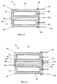
FIG. 6 zeigt eine noch weiter abgewandelte Ausführungsform einer elektrochemischen Energiequelle,
wie sie in dem vorliegend beschriebenen Implantat 10 verwendet wird. Das Gehäuse
24 ist hierbei in drei Gehäuseabschnitte unterteilt, einen ersten die Anode 26 umgebenden
Gehäuseabschnitt 46, einen zweiten die Kathode 28 umgebenden Gehäuseabschnitt
48 sowie einen dritten zwischen dem ersten und zweiten Gehäuseabschnitt angeordneten
Gehäuseabschnitt 66. Zwischen den Gehäuseabschnitten ist jeweils ein Isolator 50 angeordnet.
Im Raum zwischen der Anode 26 und der Kathode 28 sind hierbei zwei Potentialsonden
68 und 70 angeordnet, die mittels eines Diaphragmas 72 elektrisch gegeneinander isoliert
sind. Handelt es sich bei dem Gehäuse 24 um ein elektrisch leitfähiges Gehäuse, so können
die Potentialsonden 68 und 70 analog zu FIG. 5 durch die Isolatoren 50 geführt sein, um für
eine Isolation zwischen den Potentialsonden und dem Gehäuse zu sorgen.FIG. 6 shows an even further modified embodiment of an electrochemical energy source,
as used in the
Bei der in FIG. 6 dargestellten Ausführungsform einer implantatseitigen elektrochemischen
Energiequelle 14 ist ferner der dritte Gehäuseabschnitt 66 mit einem Abgriff 74 versehen,
an welchem über eine Leitung 76 das Potential des dritten Gehäuseabschnitts abgegriffen
werden kann.In the case of FIG. 6 shown embodiment of an implant-side electrochemical
The
Es versteht sich, daß die vorliegend beschriebenen Ausführungsformen in beliebiger Weise
miteinander kombiniert werden können, sofern für eine geeignete elektrische Isolation zwischen
den einzelnen elektrisch leitfähigen Bauteilen, insbesondere den Elektroden, den
Potentialsonden und gegebenenfalls dem Gehäuse, gesorgt ist. So ist in FIG. 6 ein Isolator
78 angedeutet, um die Potentialsonde 70 gegen das elektrisch leitfähige Gehäuse 24 abzuschirmen.
Ein derartiger Isolator wird bei der in FIG. 6 gezeigten Ausführungsform zwar
eigentlich nicht benötigt, da dessen Funktion von dem zwischen dem ersten und dem dritten
Gehäuseabschnitt angeordneten isolierenden Verbindungsstück 50 bereits erfüllt wird, ist
aber dann erforderlich, wenn die Potentialsonde an einer Stelle eingesetzt wird, wo kein
derartiger Isolator bereits in die Gehäusewand integriert ist.It is understood that the embodiments described herein in any manner
can be combined with each other, provided that there is suitable electrical insulation between
the individual electrically conductive components, in particular the electrodes
Potential probes and, if necessary, the housing. So in FIG. 6 an
Da bei dem vorstehend beschriebenen Implantat bereits zum Zeitpunkt der Produktion Meßsonden zur Verfügung stehen, lassen sich lange vor dem geplanten Einsatz Kontrollmessungen durchführen, die, abhängig von der verwendeten Technologie, zu dann noch durchführbaren Nachbesserungen Anlaß geben können. Kontrollmessungen können dabei einfache Messungen von Potentialdifferenzen zwischen der Bezugselektrode und einer aktiven Elektrode sein. Aber auch komplexere Meßverfahren, z.B. (cyclo)voltammetrische Untersuchungen mit Gleichstrom- oder aber kombinierten Gleich-/Wechselstromanregungssignalen sowie impedanzspektroskopische Messungen und allgemein alle dem Fachmann geläufigen elektroanalytischen Methoden, die der jeweiligen Untersuchung oder Prüfung dienlich sind, können mit dem geschilderten Aufbau der in dem Implantat vorgesehenen elektrischen Energiequelle in Kombination mit kommerziell erhältlichen Meßapparaturen durchgeführt werden. Der Zeitpunkt solcher Messungen wird bereits während des Produktionsablaufs anzusetzen sein. Bis zum Einsatz des Implantats können derartige Messungen zur Kontrolle der Stabilität und Einsatzfähigkeit durchgeführt werden, Besondere Aufmerksamkeit kommt solchermaßen erfaßbaren Elektrodenpotentialen jedoch während des Einsatzes zu. Beispielsweise während eines Entladevorgangs wird es nun erstmals möglich, anhand des Verhaltens derjenigen Elektrode, die zuerst in eine unerwünschte oder schädliche Potentialregion gerät, den Entladevorgang zu unterbrechen. Folgeprozesse können dann sinnvoll und den Gegebenheiten entsprechend eingeleitet werden. Während des Ladens kann ebenso gezielt unterbrochen werden, wenn bereits eine Elektrode in einen unerwünschten oder sogar schädlichen Potentialbereich gerät. Es sei nochmals betont, daß gerade dieser Fall bei konventionellen Zwei-Elektroden-Anordnungen nicht zwingend erfaßt wird, und somit ohne Wissen und vor allem Kontrollmöglichkeit des Benutzers die elektrische Energiequelle des Implantats irreversibel geschädigt werden kann, was sich grundsätzlich negativ auf die Gesamtlebensdauer des Implantats auswirkt.As with the implant described above, measuring probes already at the time of production control measurements can be made long before the planned use perform, depending on the technology used, then still feasible Can give cause for improvements. Control measurements can be simple Measurements of potential differences between the reference electrode and an active electrode his. But also more complex measuring methods, e.g. (Cyclo) voltammetric studies with DC or combined DC / AC excitation signals as well as impedance spectroscopic measurements and generally all those familiar to the person skilled in the art electroanalytical methods that are useful for the respective investigation or testing, can with the described structure of the electrical provided in the implant Energy source carried out in combination with commercially available measuring equipment become. The time of such measurements is already during the production process to be scheduled. Such measurements can be used as a control until the implant is used the stability and usability are carried out, special attention comes electrode potentials detectable in this way, however, during use. For example during an unloading process, it is now possible for the first time based on the behavior of the electrode first in an unwanted or harmful potential region device to interrupt the unloading process. Follow-up processes can then make sense and be initiated according to the circumstances. While charging can also be targeted be interrupted if an electrode is already in an unwanted or even harmful potential device. It should be emphasized again that this is precisely the case with conventional Two-electrode arrangements are not necessarily detected, and therefore without Knowledge and above all the ability of the user to control the electrical energy source of the Implant can be irreversibly damaged, which is fundamentally negative for the Overall lifespan of the implant affects.
Das vorliegend beschriebene Konzept, bei einem Implantat eine elektrische Energiequelle einzusetzen, bei welcher zwecks Ermittlung und Überwachung des Zustandes der Energiequelle eine oder mehrere Potentialmessungen zusätzlich zu der Erfassung der einzelnen Elektrodenpotentiale möglich sind, läßt sich wie oben erwähnt ferner auch mit Superkondensatoren insbesondere mit Doppelschichtkondensatoren, Redoxkondensatoren oder Pseudokondensatoren, sowie mit Brennstoffzellen realisieren.The concept described here, an electrical energy source for an implant to be used for the purpose of determining and monitoring the state of the energy source one or more potential measurements in addition to the detection of the individual As mentioned above, electrode potentials are also possible with supercapacitors in particular with double layer capacitors, redox capacitors or Realize pseudo capacitors, as well as with fuel cells.
Claims (12)
Applications Claiming Priority (2)
| Application Number | Priority Date | Filing Date | Title |
|---|---|---|---|
| DE19837863A DE19837863C1 (en) | 1998-08-20 | 1998-08-20 | Medical implant with electric energy source |
| DE19837863 | 1998-08-20 |
Publications (1)
| Publication Number | Publication Date |
|---|---|
| EP0981262A2 true EP0981262A2 (en) | 2000-02-23 |
Family
ID=7878191
Family Applications (1)
| Application Number | Title | Priority Date | Filing Date |
|---|---|---|---|
| EP98121614A Withdrawn EP0981262A2 (en) | 1998-08-20 | 1998-11-12 | Implant |
Country Status (5)
| Country | Link |
|---|---|
| US (1) | US6192272B1 (en) |
| EP (1) | EP0981262A2 (en) |
| AU (1) | AU747384B2 (en) |
| CA (1) | CA2270689C (en) |
| DE (1) | DE19837863C1 (en) |
Cited By (2)
| Publication number | Priority date | Publication date | Assignee | Title |
|---|---|---|---|---|
| EP1073132A1 (en) * | 1999-07-30 | 2001-01-31 | IMPLEX Aktiengesellschaft Hearing Technology | Secondary electrochemical cell |
| CN102545310A (en) * | 2011-11-29 | 2012-07-04 | 卢小平 | Power supplying method and power supplying device of aquatic electric toy |
Families Citing this family (17)
| Publication number | Priority date | Publication date | Assignee | Title |
|---|---|---|---|---|
| CA2411782A1 (en) | 2000-06-30 | 2002-01-17 | Cochlear Limited | Cochlear implant |
| DE10041727C2 (en) * | 2000-08-25 | 2003-04-10 | Cochlear Ltd | Implantable hermetically sealed housing for an implantable medical device |
| DE10041728A1 (en) | 2000-08-25 | 2002-03-21 | Implex Hear Tech Ag | Implantable medicinal device with hermetically sealed housing has storage device accommodated directly within hermetically sealed housing without housing of its own |
| US7597715B2 (en) | 2005-04-21 | 2009-10-06 | Biomet Manufacturing Corp. | Method and apparatus for use of porous implants |
| US8123814B2 (en) | 2001-02-23 | 2012-02-28 | Biomet Manufacturing Corp. | Method and appartus for acetabular reconstruction |
| DE10115429A1 (en) * | 2001-03-29 | 2002-05-02 | Siemens Audiologische Technik | Hearing aid for wearing behind the ear has an input converter, a signal-processing device, an output converter and a source of voltage including a fuel cell |
| DE10295167D2 (en) * | 2001-11-01 | 2004-10-14 | Mir Chem Gmbh | Device and method for measuring an operating parameter of an electrochemical cell in space and time resolution |
| AU2003904086A0 (en) | 2003-08-04 | 2003-08-21 | Cochlear Limited | Implant battery short circuit protection |
| DE102005018128A1 (en) * | 2004-10-12 | 2006-04-13 | Restate Patent Ag | Electro-medical implant |
| US8066778B2 (en) * | 2005-04-21 | 2011-11-29 | Biomet Manufacturing Corp. | Porous metal cup with cobalt bearing surface |
| US8266780B2 (en) * | 2005-04-21 | 2012-09-18 | Biomet Manufacturing Corp. | Method and apparatus for use of porous implants |
| US8292967B2 (en) * | 2005-04-21 | 2012-10-23 | Biomet Manufacturing Corp. | Method and apparatus for use of porous implants |
| US8021432B2 (en) | 2005-12-05 | 2011-09-20 | Biomet Manufacturing Corp. | Apparatus for use of porous implants |
| US7635447B2 (en) * | 2006-02-17 | 2009-12-22 | Biomet Manufacturing Corp. | Method and apparatus for forming porous metal implants |
| JP4384213B2 (en) * | 2007-09-18 | 2009-12-16 | トヨタ自動車株式会社 | Secondary battery status detection device |
| EP2205188B1 (en) * | 2007-09-25 | 2014-04-09 | Biomet Manufacturing Corp. | Cementless tibial tray |
| EP2828905A1 (en) * | 2012-03-21 | 2015-01-28 | Li-Tec Battery GmbH | Converter cell with a cell housing, battery with at least two of said converter cells, and method for manufacturing a converter cell |
Family Cites Families (4)
| Publication number | Priority date | Publication date | Assignee | Title |
|---|---|---|---|---|
| DE2622245A1 (en) * | 1976-05-19 | 1977-12-01 | Bbc Brown Boveri & Cie | Discharge state indicator for sulphur sodium cells - with voltmeter across auxiliary anode and sulphur cathode |
| US4606350A (en) * | 1984-11-28 | 1986-08-19 | Telectronics N.V. | Pacemaker battery impedance test circuit and method of operation |
| US5817130A (en) * | 1996-05-03 | 1998-10-06 | Sulzer Intermedics Inc. | Implantable cardiac cardioverter/defibrillator with EMI suppression filter with independent ground connection |
| US6038473A (en) * | 1997-04-08 | 2000-03-14 | Survivalink Corporation | Defibrillator battery with dual cell stack configuration |
-
1998
- 1998-08-20 DE DE19837863A patent/DE19837863C1/en not_active Expired - Fee Related
- 1998-11-12 EP EP98121614A patent/EP0981262A2/en not_active Withdrawn
-
1999
- 1999-04-29 CA CA002270689A patent/CA2270689C/en not_active Expired - Fee Related
- 1999-04-30 AU AU26017/99A patent/AU747384B2/en not_active Ceased
- 1999-05-14 US US09/311,564 patent/US6192272B1/en not_active Expired - Lifetime
Cited By (4)
| Publication number | Priority date | Publication date | Assignee | Title |
|---|---|---|---|---|
| EP1073132A1 (en) * | 1999-07-30 | 2001-01-31 | IMPLEX Aktiengesellschaft Hearing Technology | Secondary electrochemical cell |
| US7232625B2 (en) | 1999-07-30 | 2007-06-19 | Cochlear Limited | Secondary electrochemical cell |
| US7713651B2 (en) | 1999-07-30 | 2010-05-11 | Cochlear Limited | Electrochemical cell |
| CN102545310A (en) * | 2011-11-29 | 2012-07-04 | 卢小平 | Power supplying method and power supplying device of aquatic electric toy |
Also Published As
| Publication number | Publication date |
|---|---|
| CA2270689C (en) | 2002-10-22 |
| US6192272B1 (en) | 2001-02-20 |
| CA2270689A1 (en) | 2000-02-20 |
| DE19837863C1 (en) | 1999-10-28 |
| AU747384B2 (en) | 2002-05-16 |
| AU2601799A (en) | 2000-03-09 |
Similar Documents
| Publication | Publication Date | Title |
|---|---|---|
| DE19837863C1 (en) | Medical implant with electric energy source | |
| DE3536111C2 (en) | Test device and test method for determining the remaining life of a battery | |
| DE102016201026B4 (en) | Method and device for determining a residual capacity of a lead-acid battery | |
| DE102017006334B3 (en) | Method and device for detecting and avoiding degradative processes during charging of rechargeable battery cells and their use | |
| WO2015014764A2 (en) | Electrochemical storage module and method for examining an electrochemical storage cell in a module | |
| DE102019125236A1 (en) | Battery cell with a diagnostic unit, method for diagnosing the condition of a battery cell, battery and motor vehicle with a battery | |
| DE102011082288B4 (en) | Energy storage device with a plurality of integrated electrical energy stores | |
| WO2011047908A1 (en) | Energy source for electric current comprising a sensor device for determining a charge state of the energy source | |
| DE102012018126A1 (en) | Device for monitoring secondary lithium-ion-cell in lithium-ion-battery, has reference electrode and negative electrode connected with measuring unit for determining electrical voltage between reference and negative electrodes | |
| DE102015226296A1 (en) | Accumulator cell and method for producing and operating an accumulator cell | |
| EP4067890A1 (en) | Detection of moisture in an electronic circuit | |
| WO2020201009A1 (en) | Two-part reference electrode | |
| DE2622245A1 (en) | Discharge state indicator for sulphur sodium cells - with voltmeter across auxiliary anode and sulphur cathode | |
| DE102019203687A1 (en) | Method for diagnosing exhaust gas sensors | |
| DE102015222051A1 (en) | Electrode unit for a battery cell and method for examining an electrode unit | |
| DE102013220178A1 (en) | Device and method for testing the electrical insulation of cell housings of a battery module | |
| DE102015006545B4 (en) | Measuring method for determining the cycle stability of individual battery components | |
| AT523526B1 (en) | Method, device and system for determining a capacitance value of a grounding capacitance of an ungrounded power network | |
| DE102022102499B4 (en) | Measuring and monitoring method for an isolation device and a battery system | |
| EP2913882B1 (en) | Battery monitoring system, battery assembly with the battery monitoring system and method for operating the battery assembly | |
| WO2003041209A2 (en) | Device and method for the temporally and spatially dependent measuring of an operating parameter of an electrochemical cell | |
| DE102022001530B4 (en) | Method for operating a high-voltage energy storage device, high-voltage energy storage device and a motor vehicle | |
| EP2378604A2 (en) | Device, battery and method for determining the electrolyte level of a battery's electrochemical cell | |
| DE102008024812B4 (en) | Electrochemical storage battery | |
| DE102020110262A1 (en) | Accumulator cell and accumulator |
Legal Events
| Date | Code | Title | Description |
|---|---|---|---|
| PUAI | Public reference made under article 153(3) epc to a published international application that has entered the european phase |
Free format text: ORIGINAL CODE: 0009012 |
|
| AK | Designated contracting states |
Kind code of ref document: A2 Designated state(s): AT BE CH CY DE DK ES FI FR GB GR IE IT LI LU MC NL PT SE |
|
| AX | Request for extension of the european patent |
Free format text: AL;LT;LV;MK;RO;SI |
|
| RAP1 | Party data changed (applicant data changed or rights of an application transferred) |
Owner name: IMPLEX AKTIENGESELLSCHAFT HEARING TECHNOLOGY |
|
| RAP1 | Party data changed (applicant data changed or rights of an application transferred) |
Owner name: COCHLEAR LIMITED |
|
| STAA | Information on the status of an ep patent application or granted ep patent |
Free format text: STATUS: THE APPLICATION HAS BEEN WITHDRAWN |
|
| 18W | Application withdrawn |
Effective date: 20041130 |