EP0982005A2 - Angularly adjustable powered surgical handpiece - Google Patents
Angularly adjustable powered surgical handpiece Download PDFInfo
- Publication number
- EP0982005A2 EP0982005A2 EP99306242A EP99306242A EP0982005A2 EP 0982005 A2 EP0982005 A2 EP 0982005A2 EP 99306242 A EP99306242 A EP 99306242A EP 99306242 A EP99306242 A EP 99306242A EP 0982005 A2 EP0982005 A2 EP 0982005A2
- Authority
- EP
- European Patent Office
- Prior art keywords
- axis
- rotatable
- handpiece
- sleeve
- relative
- Prior art date
- Legal status (The legal status is an assumption and is not a legal conclusion. Google has not performed a legal analysis and makes no representation as to the accuracy of the status listed.)
- Withdrawn
Links
Images


Classifications
-
- A—HUMAN NECESSITIES
- A61—MEDICAL OR VETERINARY SCIENCE; HYGIENE
- A61B—DIAGNOSIS; SURGERY; IDENTIFICATION
- A61B17/00—Surgical instruments, devices or methods, e.g. tourniquets
- A61B17/32—Surgical cutting instruments
- A61B17/320016—Endoscopic cutting instruments, e.g. arthroscopes, resectoscopes
- A61B17/32002—Endoscopic cutting instruments, e.g. arthroscopes, resectoscopes with continuously rotating, oscillating or reciprocating cutting instruments
-
- A—HUMAN NECESSITIES
- A61—MEDICAL OR VETERINARY SCIENCE; HYGIENE
- A61B—DIAGNOSIS; SURGERY; IDENTIFICATION
- A61B17/00—Surgical instruments, devices or methods, e.g. tourniquets
- A61B17/28—Surgical forceps
- A61B17/29—Forceps for use in minimally invasive surgery
- A61B2017/2926—Details of heads or jaws
- A61B2017/2927—Details of heads or jaws the angular position of the head being adjustable with respect to the shaft
Definitions
- the invention relates to powered surgical instruments.
- the invention relates to a handpiece to which a variety of surgical tools may be attached.
- the invention relates to the method and apparatus by which the collet mechanism holding the tool may be attached to the handpiece and selectively adjustable, i.e. bendable, to one of a plurality of positions relative to the handpiece body.
- Surgical handpieces for driving a variety of surgical tools are well known for both open and closed surgical procedures (i.e. endoscopic, arthroscopic, etc.).
- Such instruments generally comprise a powered handpiece having a distal end to which a variety of surgical tools may be attached by means of some chuck or collet mechanism.
- the handpiece receives power at its proximal end from any one of a number of sources (e.g. pneumatic, electric, battery) and contains a drive means for providing rotary (or other) power to the surgical tool. It is known to provide attachments for the distal tips of handpieces by which the various tools may be oriented at selected positions relative to the handpiece body.
- the axis of the tool is able to be placed by a user either in a position coaxial to the drive axis of the handpiece body, i.e. a straight orientation, or one or more other positions in which the tool axis intersects with but is angled relative to the drive axis of the handpiece body, i.e. an angled orientation.
- drive axis means the main axis along which power is transmitted (e.g. a rotating drive shaft), and as such handpieces having all configurations (pencil-type, pistol grip, etc.) will have such a drive axis.
- Such adjustability of tool orientations is usually provided by fixed attachments interposed between the collet mechanism and the handpiece.
- the Hall Ultrapower® Drill System manufactured by Linvatec Corporation, Largo, Florida 33773 provides a variety of burr guards in various lengths and fixed angular orientations in order to enable a user to choose between using the tool in coaxial alignment with the handpiece or in a fixed angular orientation relative to the handpiece.
- the angled burr guards a user must have available both straight and angled attachments in order to have the flexibility of choosing a particular orientation at the time of surgery. It would be preferable, and it is an object of this invention, to enable the user to minimize the number of attachments that must be held in inventory while still enabling the user to select a particular tool orientation at the time of surgery.
- the coupling means includes a non-rotatable sleeve attached to the handpiece and a rotatable sleeve attached to the collet holding the surgical tool.
- the sleeves have abutting inclined faces which are angled relative to the handpiece axis so that relative rotation of the components causes their axes to be positionable either in alignment or at a predetermined angular orientation.
- the coupling mechanism includes a tubular coupling link to enclose a drive train to power the tool, thus enabling relative rotation between the rotatable and non-rotatable sleeves while also enabling translation of power from the handpiece to the surgical tool.
- Handpiece 10 may be any one of a variety of surgical handpieces but, for the purposes of explaining the subject invention, handpiece 10 is shown in the form of an electrically powered, pencil type handpiece. It will be understood that the subject invention may be used with any number of other handpiece types.
- Handpiece 10 includes a proximal end 12 attached to a cable restraining release 14 and an electrical cable 15. Obviously, the handpiece may be driven by other than electrical means. Handpiece 10 also includes a distal end 16 to which is secured a conventional tool holder such as collet mechanism 18 via an intermediate, variable orientation coupling 20. It will be understood that handpiece 10 and collet mechanism 18 may be conventional and do not form any part of the subject invention. Handpiece 10 has a drive axis 21 adjacent its distal end 16. Since the handpiece may have a variety of configurations, it will be understood that only the axis near the distal end will be referred to in describing the invention, Similarly, collet mechanism 18 has an axis 23 near its proximal end.
- Power is transmitted from handpiece 10 to the collet mechanism 18 via an elongated drive train comprising intermediate drive shafts 22 and 24 aligned along axes 21 and 23, respectively, and joined by, for example, a mating crown gear assembly 26 which enables the transmission of rotational motion from shaft 22 to shaft 24 as the latter is placed in various angular positions as will be understood below.
- Other mating drive couplings may also be used such as constant velocity universal joints.
- Coupling section 20 surrounds the drive train and comprises a proximal stationary, non-rotatable cylindrical sleeve 30 having axis 21, a distal rotatable, indexing cylindrical sleeve 32 having axis 23 and a hollow tubular or cylindrical coupling body 34.
- sleeve 30 is threadably or otherwise fixedly joined at its proximal end to the distal end 16 of the handpiece and rotatable indexing sleeve 32 is threadably or otherwise fixedly joined at its distal end to the proximal end of the collet mechanism 18.
- the sleeves 30 and 32 are movable relative to each other, but fixed relative to the handpiece and collet, respectively.
- sleeve 32 is described as being rotatable relative to sleeve 30, it will be understood below that the motion of sleeve 32 is more in the nature of a nutation. That is, axis 23 nutates about axis 21 as sleeve 32 is turned.
- Sleeve 30 and indexing sleeve 32 are held in abutting relationship by spring-loaded tubular coupling body 34 which has a threaded proximal end 42 and a partially spherical distal end 44.
- axis 52 of the coupling body 34 is coaxially aligned with handpiece axis 21 and with axis 23 of shaft 24.
- a coil spring 46 is interposed between the inner tubular or cylindrical surface of the sleeve 30 and the outer surface of coupling body 34 in an annular space 47 and is retained in place between radially inwardly extending annular flange 48 and nut 50 threaded onto the proximal end 42 of the cylindrical body.
- Radially inwardly extending annular flange 48 has an axially aligned opening sized and shaped to receive the outer surface of body 34 which, in the preferred embodiment, is cylindrical.
- the outer diameter of nut 50 is sized and shaped to be slidably received within the interior of sleeve 30.
- the body 34 is thus maintained in coaxial alignment with the axis 21 of the handpiece and biased in a proximal direction to urge sleeves 30 and 32 together as will be understood below.
- rotatable indexing sleeve 32 has proximal and distal ends 60 and 62, respectively, and non-rotatable sleeve 30 has proximal and distal ends 64 and 66, respectively.
- distal end 66 of non-rotatable sleeve 30 and the proximal end 60 of sleeve 32 have mutually complementarily shaped features enabling these ends to be held together in either coaxial alignment as shown in Figure 1 or at some predetermined angle which in the preferred embodiment is approximately 20°, as shown in Figure 2.
- Stationary sleeve 30 is a tubular body 100 having a thread 102 at its proximal end 64, an inclined distal surface 106 at its distal end 66 and a main axis 108.
- the exterior surface 110 of body 100 may be shaped so as to blend with and serve as part of the exterior surface of the handpiece as best seen in Figures 1 and 2.
- surface 110 is cylindrical.
- the interior surface 112, which may also be cylindrical, defines a chamber 107 for retaining spring 46, nut 50 and coupling body 40 (as best seen in Figures 1, 2 and 5).
- Chamber 107 is sufficiently large to receive all these components and is bounded at its distal end by annular flange 48.
- Distal surface 106 has an annular face 120 which lies in a plane angled at an angle A relative to a plane perpendicular to axis 108.
- the distal end 106 also defines a cylindrical chamber 122 having an axis 124 inclined relative to axis 108 at an angle B.
- Chamber 122 includes a pair of diametrically opposed, radially inwardly extending tabs 125 and 126 having a predetermined arcuate length and situated within a plane parallel to that of face 120 and spaced proximally therefrom by a predetermined distance.
- Tabs 125 and 126 are arcuate by virtue of the fact that they follow the contour of the inside cylindrical surface of chamber 122. Adjacent each tab 125 and 126, face 120 is provided with a diametrically opposed pair of shallow detents 128 and 130 which, as best seen in Figures 4 and 6, each take the form of arcuate shallow triangular recess having a large opening on face 120 and an apex spaced proximally therefrom.
- Indexing sleeve 32 comprises a tubular body 140 having an exterior surface 142, a proximal end 60, a distal end 62 and an axis 148.
- Exterior surface 142 has a shape comparable to that of the exterior surface of stationary sleeve 30 and serves as a portion of the exterior surface of the handpiece as best seen in Figures 1 and 2.
- exterior surface 142 is cylindrical and has a diameter equal to that of exterior surfaces of body 100 ( Figure 6) and collet 18 ( Figure 1).
- Proximal end 60 is provided with locking features 144 intended to complementarily mate with the distal end 66 of sleeve 30 and to provide a selectively lockable engagement therewith.
- Proximal end 60 is also provided with an annular face 150 intended to be placed in abutting relationship with face 120 of the stationary sleeve. Face 150 is provided with a pair of diametrically opposed projections 152 and 154 intended to be matingly received within detents such as triangular recesses 128 and 130. As will be understood below, the recesses and projections may be alternatingly engaged depending upon the angular orientation of sleeve 32 relative to sleeve 30. That is, recess/projection pairings could be, for example, 128/154 and 130/152 if the tool is positioned in alignment with the handpiece axis, or 128/152 and 130/154 if the tool is angled.
- a raised spacing cylinder 156 extends distally from face 150 and a second spacing cylinder 158 extends distally from cylinder 156.
- the distal end of cylinder 158 is provided with a pair of diametrically opposed tabs 160 and 162.
- tabs 160 and 162 have an outer arcuate surface having a diameter equal to that of spacing cylinder 156 thereby producing arcuate gaps 163 and 165 between tabs 160 and 162 and spacing cylinder 156 as seen in Figure 11. This results in arcuate spaces 167 and 168 behind tabs 160 and 162, respectively.
- indexing sleeve 32 has a distal end 182 and a proximal end 184 which is provided with spherical wall surface 186.
- An aperture 188 at the proximal end is sized to receive the cylindrical portion of coupling body 40 so that wall surface 186 may engage the spherical distal end 44 of the coupling body.
- Aperture 188 is smaller than the diameter of the spherical surfaces in order to maintain longitudinal tension on the spherical surfaces to keep the components together.
- sleeve 32 is able to nutate about sleeve 30 while faces 120 and 150 remain in contact.
- spring 46 will urge coupling body 34 proximally so that the spherical distal end 44 may urge the partially enclosed proximal end 184 of sleeve 32 in a proximal direction in order to maintain contact between surfaces 120 and 150.
- Some gap 170 is necessary if projections 152, 154 and their corresponding recesses 124, 126 are utilized. That is, since rotation of sleeve 32 relative to sleeve 30 is necessary in order to reposition sleeve 32 from the straight orientation of Figures 14 and 15 to the angular orientation shown in Figures 16 and 17, the projections are necessarily pushed from their corresponding recesses as one sleeve rotates relative to the other.
- FIG. 18-26 there is shown an alternate embodiment of the bendable collet mechanism constructed in accordance with the principles of this invention.
- This alternate embodiment minimizes the degree to which lateral forces on the tool can cause angular misalignment of the components of the coupling.
- handpiece 10 and collet 18 may be joined by coupling mechanism 200 instead of coupling mechanism 20.
- coupling mechanism 200 instead of coupling mechanism 20.
- all of the internal components associated with actually driving the surgical tool have been omitted from these drawings.
- coupling 200 comprises a stationary sleeve 202, a rotatable indexing sleeve 204 and a cylindrical connecting link 206.
- Figures 19 and 20 are orthogonal views in that Figure 19 is a cross-section taken through a vertical plane of the handpiece and coupling 200, and Figure 20 is a cross-section taken through a horizontal plane of the coupling.
- the outer surfaces of sleeves 202 and 204 are identical to the corresponding outer surfaces of sleeves 30 and 32 of the previous embodiment.
- connecting link 206 and nut 208 threadably attached to its proximal end are also functionally similar to link 40 and nut 50 of the previous embodiment.
- the axial length of connecting link 206 may be shorter than that of link 40 because of the arrangement of the springs to be discussed below.
- the spring biasing the connecting link proximally was an external spring located between stationary sleeve 30 and the outer surface of the connecting link 40
- the bias between stationary sleeve 202 and rotatable sleeve 204 is achieved by an internal spring structure biasing the rotatable sleeve distally.
- this internal spring structure comprises engaging elements which, in this embodiment, are a pair of diametrically opposed internal spring assemblies 220 and 222 situated within diametrically opposed chambers 224 and 226 formed in the body of stationary sleeve 202.
- Spring assemblies 220, 222 each comprise a ball plunger; i.e. an externally threaded cylinder 27 containing a spring 228 and having a ball 230 at its distal end, the spring serving to bias the ball in a distal direction.
- the spring receiving chambers 224 and 226 are threaded to receive the threaded cylinders of the ball plungers, and each of the threaded cylinders has an opening at its distal end to enable balls 230 to protrude from opening 232 in distally facing surface 234 of stationary sleeve 202. Balls 230 are thus biased against a proximally facing annular surface 240 of stationary sleeve 204.
- each threaded cylinder 227 has a slotted end 244 to facilitate turning the cylinder into its associated chamber.
- the end 244 is reduced at its distal-most end to provide an aperture 246 in order to retain ball 230 within the insert.
- each cylinder 227 may be assembled with a spring and ball within its interior prior to being turned or threaded into either chamber 224 or 226.
- balls 230 are biased distally against and received in diametrically opposed recesses 250 and 252 of proximally facing annular surface 240.
- the stationary and rotatable sleeves 202 and 204 are axially aligned as best seen in the elevational view of Figure 25.
- the balls and recesses lie within a plane perpendicular to that of Figure 25 and are not seen in this view. Because annular surfaces 234 and 240 are angled relative to the axis of the sleeves, relative rotation of the sleeves from the position shown in Figures 23 and 25 will result in an angled configuration as shown in Figures 24 and 26.
- coupling 200 does not require a gap such as gap 170 between the tabs used in the previous embodiment.
- the spring loaded balls 230 Upon rotating sleeve 204 relative to sleeve 202, the spring loaded balls 230 will be pushed back into spring assemblies 220 and 222 thereby removing the balls from recesses 250 and 252 thereby enabling the sleeves 202 and 204 to be repositioned.
- This embodiment thus minimizes the likelihood of exposing the interior components of the handpiece and coupling to contaminates in the ambient area.
- a pair of diametrically opposed recesses 250 and 252 are utilized in order to provide the bendable collet mechanism with two selectable positions, it will be understood that one or more additional pairs of diametrically arranged recesses may be added in order to position rotatable indexing sleeve 204 at a variety of selectable angular orientations relative to the handpiece body.
- a third embodiment of the invention is shown in Figure 27 as coupling mechanism 300 comprising stationary sleeve 302, a rotatable indexing sleeve 304 and a cylindrical connecting link 306 and associated nut 308.
- the link 306 and nut 308 operate essentially identically to comparable components in the previously described embodiments.
- Sleeves 302 and 304 differ from previous embodiments only in that they are adapted to operate with a single internal spring structure 310 biasing the rotatable sleeve 304 distally.
- Spring structure 310 comprises a coil spring 312 adapted to receive, and bias distally, a locking pin 314 having an elongated body 316 and a distally facing rounded head 318.
- Spring 312 is received in a chamber 320 formed distally facing surface 322 in stationary sleeve 302 and biases the locking pin distally to seat head 318 in any one of recesses 324, 326 formed in the proximally facing surface 328 of indexing sleeve 304.
- the spring structure 310 is situated at the longer side of sleeve 302 in order to enable use of a longer, stronger spring.
- Coupling 300 operates like the previously described embodiments in that rotation of indexing sleeve 304 serves to orient the sleeve axes as desired.
- the invention enables a user to selectively position the tool relative to the handpiece by simply turning the collet mechanism relative to the handpiece and placing it into the detented positions.
- the resulting orientation of the tool axis relative to the handpiece axis will automatically be maintained without the need to use any other instruments to lock the collet in place.
- the angle of the distal axis (of the collet mechanism) may be selectively set at approximately 20° relative to the proximal axis (of the handpiece), it will be understood that other angles may be provided.
Abstract
Description
- The invention relates to powered surgical instruments. In particular, the invention relates to a handpiece to which a variety of surgical tools may be attached. Still more particularly, the invention relates to the method and apparatus by which the collet mechanism holding the tool may be attached to the handpiece and selectively adjustable, i.e. bendable, to one of a plurality of positions relative to the handpiece body.
- Surgical handpieces for driving a variety of surgical tools are well known for both open and closed surgical procedures (i.e. endoscopic, arthroscopic, etc.). Such instruments generally comprise a powered handpiece having a distal end to which a variety of surgical tools may be attached by means of some chuck or collet mechanism. The handpiece receives power at its proximal end from any one of a number of sources (e.g. pneumatic, electric, battery) and contains a drive means for providing rotary (or other) power to the surgical tool. It is known to provide attachments for the distal tips of handpieces by which the various tools may be oriented at selected positions relative to the handpiece body. Generally, the axis of the tool is able to be placed by a user either in a position coaxial to the drive axis of the handpiece body, i.e. a straight orientation, or one or more other positions in which the tool axis intersects with but is angled relative to the drive axis of the handpiece body, i.e. an angled orientation. It will be understood that the term "drive axis" means the main axis along which power is transmitted (e.g. a rotating drive shaft), and as such handpieces having all configurations (pencil-type, pistol grip, etc.) will have such a drive axis.
- Such adjustability of tool orientations is usually provided by fixed attachments interposed between the collet mechanism and the handpiece. For example, the Hall Ultrapower® Drill System manufactured by Linvatec Corporation, Largo, Florida 33773 provides a variety of burr guards in various lengths and fixed angular orientations in order to enable a user to choose between using the tool in coaxial alignment with the handpiece or in a fixed angular orientation relative to the handpiece. However, because of the fixed nature of the angled burr guards, a user must have available both straight and angled attachments in order to have the flexibility of choosing a particular orientation at the time of surgery. It would be preferable, and it is an object of this invention, to enable the user to minimize the number of attachments that must be held in inventory while still enabling the user to select a particular tool orientation at the time of surgery.
- It is also known to provide adjustability of tool orientation by a variable attachment interposed between the collet mechanism and the handpiece. One such device is shown in U.S. Patent 636,476 (Webster) as embodied in a dental handpiece having the drill adjustable into a variety of positions relative to the handpiece body. The chuck mechanism in this device must be locked into a selected position by placing a retaining pin in corresponding apertures.
- It is an object of this invention to produce a bendable collet mechanism for a powered surgical handpiece so that a surgical tool may be selectively placed into one of a plurality of positions relative to the handpiece body and automatically held in the selected position during use.
- It is another object of this invention to provide such an adjustable collet mechanism which is usable without the necessity for other tools to lock or unlock the collet mechanism from any of its possible positions relative to the handpiece body.
- It is also an object of this invention to provide a system for enabling a user to selectively choose between straight and angled tool orientations.
- These and other objects of the invention are achieved by the preferred embodiment disclosed herein which is an adjustable collet mechanism for a surgical handpiece which enables the surgical tool driven by the handpiece to be oriented at selected angular positions relative to the handpiece axis. The coupling means includes a non-rotatable sleeve attached to the handpiece and a rotatable sleeve attached to the collet holding the surgical tool. The sleeves have abutting inclined faces which are angled relative to the handpiece axis so that relative rotation of the components causes their axes to be positionable either in alignment or at a predetermined angular orientation. The coupling mechanism includes a tubular coupling link to enclose a drive train to power the tool, thus enabling relative rotation between the rotatable and non-rotatable sleeves while also enabling translation of power from the handpiece to the surgical tool.
-
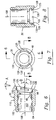
- Figure 1 is a side elevational view partially in cross-section of a handpiece provided with an adjustment mechanism constructed in accordance with the principles of this invention.
- Figure 2 is a view of Figure 1 showing the handpiece in an angled orientation.
- Figure 3 is a front perspective view of the handpiece of Figure 1 in cross-section with various internal components removed for clarity.
- Figure 4 is an expanded front perspective view of the adjustment mechanism, partially in cross-section.
- Figure 5 is a partially expanded cross-sectional view of the adjustment mechanism taken along the line 5-5 of Figure 1, omitting some components for clarity.
- Figure 6 is a side elevational view in cross-section of the non-rotatable sleeve component of the adjustment mechanism of Figure 1.
- Figure 7 is a front elevational view of the component shown in Figure 6.
- Figure 8 is a cross-sectional view of Figure 7 taken along the line 8-8.
- Figure 9 is a side elevational view of the rotatable indexing sleeve of the adjustment mechanism of Figure 1.
- Figure 10 is an elevational view of the component shown in Figure 9 taken along the line 10-10.
- Figure 11 is a top plan view of Figure 9.
- Figure 12 is a right side elevational view of Figure 11.
- Figure 13 is a cross-sectional view of Figure 12 taken along the line 13-13.
- Figures 14 and 15 are expanded and assembled side elevation views in cross-section, respectively, of the rotatable and non-rotatable sleeves of the adjustment mechanism showing the configuration of the components in a straight orientation.
- Figures 16 and 17 are expanded and assembled views, respectively, of the components of Figures 14 and 15 showing the components in an angled orientation.
- Figure 18 is a front perspective view in cross-section of an alternate embodiment of a handpiece constructed in accordance with the principles of this invention.
- Figure 19 is an expanded view of Figure 18.
- Figure 20 is an expanded view of the coupling portion of Figure 19 taken in a plane orthogonal to that of Figure 19.
- Figure 21 is an assembled view of Figure 19 showing the adjustment mechanism in coaxial alignment.
- Figure 22 is a view of Figure 21 showing the spring assemblies in place.
- Figure 23 is a plan view of Figure 22 wherein the distal end of the coupling is aligned relative to the proximal end.
- Figure 24 is a view of Figure 23 wherein the distal end of the coupling is angled relative to the proximal end.
- Figure 25 is a side elevation view of the axially aligned coupling included in Figure 18, the plane of the drawing being orthogonal to the view shown in Figure 23.
- Figure 26 is a view of Figure 25 showing the coupling in an angled configuration.
- Figure 27 is an expanded front perspective view, in cross-section, of another alternate embodiment of a handpiece constructed in accordance with the principles of this invention.
-
- A powered surgical handpiece including an adjustable (bendable) collet mechanism constructed in accordance with the principles of this invention is shown in Figures 1 and 2.
Handpiece 10 may be any one of a variety of surgical handpieces but, for the purposes of explaining the subject invention,handpiece 10 is shown in the form of an electrically powered, pencil type handpiece. It will be understood that the subject invention may be used with any number of other handpiece types. -
Handpiece 10 includes aproximal end 12 attached to acable restraining release 14 and anelectrical cable 15. Obviously, the handpiece may be driven by other than electrical means.Handpiece 10 also includes adistal end 16 to which is secured a conventional tool holder such ascollet mechanism 18 via an intermediate,variable orientation coupling 20. It will be understood thathandpiece 10 andcollet mechanism 18 may be conventional and do not form any part of the subject invention.Handpiece 10 has adrive axis 21 adjacent itsdistal end 16. Since the handpiece may have a variety of configurations, it will be understood that only the axis near the distal end will be referred to in describing the invention, Similarly,collet mechanism 18 has anaxis 23 near its proximal end. Power is transmitted fromhandpiece 10 to thecollet mechanism 18 via an elongated drive train comprisingintermediate drive shafts 22 and 24 aligned alongaxes crown gear assembly 26 which enables the transmission of rotational motion from shaft 22 toshaft 24 as the latter is placed in various angular positions as will be understood below. Other mating drive couplings may also be used such as constant velocity universal joints. -
Coupling section 20 surrounds the drive train and comprises a proximal stationary, non-rotatablecylindrical sleeve 30 havingaxis 21, a distal rotatable, indexingcylindrical sleeve 32 havingaxis 23 and a hollow tubular orcylindrical coupling body 34. In the preferred embodiment,sleeve 30 is threadably or otherwise fixedly joined at its proximal end to thedistal end 16 of the handpiece androtatable indexing sleeve 32 is threadably or otherwise fixedly joined at its distal end to the proximal end of thecollet mechanism 18. Thesleeves sleeve 32 is described as being rotatable relative tosleeve 30, it will be understood below that the motion ofsleeve 32 is more in the nature of a nutation. That is,axis 23 nutates aboutaxis 21 assleeve 32 is turned. -
Sleeve 30 andindexing sleeve 32 are held in abutting relationship by spring-loadedtubular coupling body 34 which has a threadedproximal end 42 and a partially sphericaldistal end 44. As shown in the configuration of Figure 1, axis 52 of thecoupling body 34 is coaxially aligned withhandpiece axis 21 and withaxis 23 ofshaft 24. Acoil spring 46 is interposed between the inner tubular or cylindrical surface of thesleeve 30 and the outer surface ofcoupling body 34 in anannular space 47 and is retained in place between radially inwardly extendingannular flange 48 andnut 50 threaded onto theproximal end 42 of the cylindrical body. Radially inwardly extendingannular flange 48 has an axially aligned opening sized and shaped to receive the outer surface ofbody 34 which, in the preferred embodiment, is cylindrical. The outer diameter ofnut 50 is sized and shaped to be slidably received within the interior ofsleeve 30. Thebody 34 is thus maintained in coaxial alignment with theaxis 21 of the handpiece and biased in a proximal direction to urgesleeves - As best seen in Figures 4 and 5, with the components separated for clarity,
rotatable indexing sleeve 32 has proximal anddistal ends non-rotatable sleeve 30 has proximal anddistal ends distal end 66 ofnon-rotatable sleeve 30 and theproximal end 60 ofsleeve 32 have mutually complementarily shaped features enabling these ends to be held together in either coaxial alignment as shown in Figure 1 or at some predetermined angle which in the preferred embodiment is approximately 20°, as shown in Figure 2. - The detailed structures of
stationary sleeve 30 androtatable indexing sleeve 32 are best seen by reference to Figures 6 through 13.Stationary sleeve 30 is atubular body 100 having athread 102 at itsproximal end 64, an inclineddistal surface 106 at itsdistal end 66 and amain axis 108. Theexterior surface 110 ofbody 100 may be shaped so as to blend with and serve as part of the exterior surface of the handpiece as best seen in Figures 1 and 2. In the preferred embodiment,surface 110 is cylindrical. Theinterior surface 112, which may also be cylindrical, defines achamber 107 for retainingspring 46,nut 50 and coupling body 40 (as best seen in Figures 1, 2 and 5).Chamber 107 is sufficiently large to receive all these components and is bounded at its distal end byannular flange 48.Distal surface 106 has anannular face 120 which lies in a plane angled at an angle A relative to a plane perpendicular toaxis 108. Thedistal end 106 also defines acylindrical chamber 122 having anaxis 124 inclined relative toaxis 108 at anangle B. Chamber 122 includes a pair of diametrically opposed, radially inwardly extendingtabs face 120 and spaced proximally therefrom by a predetermined distance.Tabs chamber 122. Adjacent eachtab face 120 is provided with a diametrically opposed pair ofshallow detents face 120 and an apex spaced proximally therefrom. -
Indexing sleeve 32 comprises atubular body 140 having anexterior surface 142, aproximal end 60, adistal end 62 and anaxis 148.Exterior surface 142 has a shape comparable to that of the exterior surface ofstationary sleeve 30 and serves as a portion of the exterior surface of the handpiece as best seen in Figures 1 and 2. In the preferred embodiment,exterior surface 142 is cylindrical and has a diameter equal to that of exterior surfaces of body 100 (Figure 6) and collet 18 (Figure 1).Proximal end 60 is provided with locking features 144 intended to complementarily mate with thedistal end 66 ofsleeve 30 and to provide a selectively lockable engagement therewith.Proximal end 60 is also provided with anannular face 150 intended to be placed in abutting relationship withface 120 of the stationary sleeve. Face 150 is provided with a pair of diametricallyopposed projections triangular recesses sleeve 32 relative tosleeve 30. That is, recess/projection pairings could be, for example, 128/154 and 130/152 if the tool is positioned in alignment with the handpiece axis, or 128/152 and 130/154 if the tool is angled. A raisedspacing cylinder 156 extends distally fromface 150 and asecond spacing cylinder 158 extends distally fromcylinder 156. The distal end ofcylinder 158 is provided with a pair of diametricallyopposed tabs tabs spacing cylinder 156 thereby producingarcuate gaps tabs spacing cylinder 156 as seen in Figure 11. This results inarcuate spaces tabs - The
interior 180 of indexingsleeve 32, best seen in Figure 13, has adistal end 182 and aproximal end 184 which is provided withspherical wall surface 186. Anaperture 188 at the proximal end is sized to receive the cylindrical portion ofcoupling body 40 so thatwall surface 186 may engage the sphericaldistal end 44 of the coupling body.Aperture 188 is smaller than the diameter of the spherical surfaces in order to maintain longitudinal tension on the spherical surfaces to keep the components together. Thus,sleeve 32 is able to nutate aboutsleeve 30 whilefaces - The operation of the bendable collet mechanism is best understood by reference to Figures 14 through 17 which show
stationary sleeve 30 androtatable indexing sleeve 32 with theiraxes body 34 and other components have been omitted from these drawings for clarity. As shown in these drawings, when the sleeves are aligned such thattabs tabs sleeve 32 is rotated about isaxis 148 by 90° from the position shown in Figure 14 (or that shown in Figures 15-17), thetabs tabs arcuate tab 160 will be received proximally ofarcuate tab 124 onsleeve 30, as shown in Figure 14. It will be understood that the opposite tabs are similarly engaged, but omitted for clarity. When the sleeves are so engaged and urged together by spring tension, asmall gap 170 may exist betweentab 124 andtab 160 whensurfaces spring 46 will urge couplingbody 34 proximally so that the sphericaldistal end 44 may urge the partially enclosedproximal end 184 ofsleeve 32 in a proximal direction in order to maintain contact betweensurfaces gap 170 is necessary ifprojections corresponding recesses sleeve 32 relative tosleeve 30 is necessary in order to repositionsleeve 32 from the straight orientation of Figures 14 and 15 to the angular orientation shown in Figures 16 and 17, the projections are necessarily pushed from their corresponding recesses as one sleeve rotates relative to the other. This necessarily causessurface 120 to be spaced fromsurface 150 by the height of the projection and minimizesgap 170 by movingtabs tabs spring 46 defines the degree of force with which the two sleeves are urged together, a laterally directed force on the tool to be attached tocollet mechanism 18 may result in a laterally directed force onsleeve 32 which may cause some slight angular movement of the axis ofsleeve 32 until thetabs tabs spring 46 will tend of minimize the degree of such movement. - Referring now to Figures 18-26, there is shown an alternate embodiment of the bendable collet mechanism constructed in accordance with the principles of this invention. This alternate embodiment minimizes the degree to which lateral forces on the tool can cause angular misalignment of the components of the coupling. Thus,
handpiece 10 andcollet 18 may be joined bycoupling mechanism 200 instead ofcoupling mechanism 20. For clarity, all of the internal components associated with actually driving the surgical tool have been omitted from these drawings. - As shown in Figures 18-20,
coupling 200 comprises astationary sleeve 202, arotatable indexing sleeve 204 and a cylindrical connectinglink 206. Figures 19 and 20 are orthogonal views in that Figure 19 is a cross-section taken through a vertical plane of the handpiece andcoupling 200, and Figure 20 is a cross-section taken through a horizontal plane of the coupling. - The outer surfaces of
sleeves sleeves link 206 andnut 208 threadably attached to its proximal end are also functionally similar to link 40 andnut 50 of the previous embodiment. (However, the axial length of connectinglink 206 may be shorter than that oflink 40 because of the arrangement of the springs to be discussed below.) While in the previous embodiment the spring biasing the connecting link proximally was an external spring located betweenstationary sleeve 30 and the outer surface of the connectinglink 40, incoupling 200 the bias betweenstationary sleeve 202 androtatable sleeve 204 is achieved by an internal spring structure biasing the rotatable sleeve distally. As shown in Figures 21 and 22, this internal spring structure comprises engaging elements which, in this embodiment, are a pair of diametrically opposedinternal spring assemblies opposed chambers stationary sleeve 202.Spring assemblies ball 230 at its distal end, the spring serving to bias the ball in a distal direction. Thespring receiving chambers balls 230 to protrude from opening 232 in distally facingsurface 234 ofstationary sleeve 202.Balls 230 are thus biased against a proximally facingannular surface 240 ofstationary sleeve 204. - In the preferred embodiment, each threaded
cylinder 227 has a slottedend 244 to facilitate turning the cylinder into its associated chamber. Theend 244 is reduced at its distal-most end to provide an aperture 246 in order to retainball 230 within the insert. It will be understood that eachcylinder 227 may be assembled with a spring and ball within its interior prior to being turned or threaded into eitherchamber - As best seen in Figures 23 and 24,
balls 230 are biased distally against and received in diametricallyopposed recesses annular surface 240. When the recesses are arranged as shown in Figure 23, the stationary androtatable sleeves annular surfaces - It will be understood that
coupling 200 does not require a gap such asgap 170 between the tabs used in the previous embodiment. Upon rotatingsleeve 204 relative tosleeve 202, the spring loadedballs 230 will be pushed back intospring assemblies recesses sleeves opposed recesses rotatable indexing sleeve 204 at a variety of selectable angular orientations relative to the handpiece body. - A third embodiment of the invention is shown in Figure 27 as
coupling mechanism 300 comprisingstationary sleeve 302, arotatable indexing sleeve 304 and a cylindrical connectinglink 306 and associatednut 308. Thelink 306 andnut 308 operate essentially identically to comparable components in the previously described embodiments.Sleeves rotatable sleeve 304 distally. Spring structure 310 comprises acoil spring 312 adapted to receive, and bias distally, a locking pin 314 having anelongated body 316 and a distally facingrounded head 318.Spring 312 is received in achamber 320 formed distally facingsurface 322 instationary sleeve 302 and biases the locking pin distally toseat head 318 in any one ofrecesses proximally facing surface 328 ofindexing sleeve 304. In the preferred embodiment, the spring structure 310 is situated at the longer side ofsleeve 302 in order to enable use of a longer, stronger spring. Coupling 300 operates like the previously described embodiments in that rotation of indexingsleeve 304 serves to orient the sleeve axes as desired. - The invention enables a user to selectively position the tool relative to the handpiece by simply turning the collet mechanism relative to the handpiece and placing it into the detented positions. The resulting orientation of the tool axis relative to the handpiece axis will automatically be maintained without the need to use any other instruments to lock the collet in place. While in the preferred embodiment the angle of the distal axis (of the collet mechanism) may be selectively set at approximately 20° relative to the proximal axis (of the handpiece), it will be understood that other angles may be provided.
- It will be understood by those skilled in the art that numerous other modifications and improvements may be made to the preferred embodiments of the invention disclosed herein without departing from the spirit and scope thereof.
Claims (23)
- A surgical instrument for driving a tool comprising:a handpiece having a proximal end and a distal end, said distal end having a first axis;a tool holding means having a proximal end and a distal end, said proximal end having a second axis, said tool holding means for receiving said tool at its distal end; anda variable orientation coupling means for orienting said second axis relative to said first axis, said coupling means interposed between and connected to said distal end of said handpiece and said proximal end of said tool holding means, said coupling means comprising positioning means selectively movable by a user to situate said second axis in one of a plurality of positions relative to said first axis and automatic position holding means to maintain said second axis in the selected position.
- A surgical instrument according to claim 1 further comprising said coupling means being hollow to receive therethrough an elongated drive train for transmitting driving power from said handpiece to said tool throughout all orientations of said tool relative to said handpiece.
- A surgical instrument according to claim 1 wherein said second axis of said tool holding means is maintained either in axial alignment with said first axis or in an angular orientation relative to said first axis.
- A surgical instrument according to claim 1 wherein said variable orientation coupling means comprises:a non-rotatable tubular sleeve comprising:a first body having a third axis non-rotatably attached to said distal end of said handpiece, said first body having a proximal end and a distal end, said distal end having a distally facing first surface angularly inclined relative to said third axis of said first body by a first predetermined amount;a rotatable tubular sleeve comprising:a second body having a fourth axis non-rotatably attached to said tool holding means, said second body being rotatable relative to said non-rotatable sleeve, said second body having a distal end and a proximal end, said proximal end having a proximally facing second surface angularly inclined relative to said fourth axis of said second body by a second predetermined amount;coupling body means for releasably holding said first and second surfaces together in abutting relation.
- A surgical instrument according to claim 4 wherein said first and second bodies have axial throughbores, wherein said first and second surfaces are annular and wherein said coupling body means comprises:a hollow cylindrical tubular body having a proximal end and a distal end, said tubular body axially aligned within said non-rotatable sleeve; anda generally spherical hollow link means secured to and axially aligned at the distal end of said cylindrical tubular body for joining said first and second bodies together, said link means comprising:a substantially spherical exterior wall surface secured to said distal end of said hollow tubular body for mating engagement with said rotatable sleeve, anda substantially spherical interior wall surface of said proximal end of said second body, said interior wall surface being complementarily shaped spherically to receive said substantially spherical exterior wall surface, said interior wall surface further comprising a proximal-most aperture smaller in size than said exterior wall surface to prevent distal movement of said rotatable sleeve relative to said coupling body means.
- A surgical instrument according to claim 5 wherein said coupling body means comprises:spring means for urging first and second surfaces and, therefore, said rotatable and non-rotatable sleeves, together.
- A surgical instrument according to claim 6 further comprising:detent means for positioning said first and second surfaces in abutting relation in a selected one of a plurality of predetermined positions.
- A surgical instrument according to claim 4 wherein said third axis of said non-rotatable sleeve is aligned with said first axis of said handpiece.
- A surgical instrument according to claim 4 wherein said first predetermined amount equals said second predetermined amount.
- A surgical instrument according to claim 4 wherein said first and second bodies have cylindrical external surfaces adjacent the junction of said first and second inclined surfaces, said external surfaces being equal in diameter.
- A surgical instrument according to claim 10 wherein the outer surface of said distal end of said handpiece has a first diameter and the surfaces of each of said sleeves have a second diameter equal to said first diameter.
- A surgical instrument according to claim 6 wherein said spring means is adapted to urge said substantially spherical exterior wall surface proximally.
- A surgical instrument according to claim 6 wherein said spring means is adapted to urge said substantially spherical interior wall surface distally.
- A surgical instrument according to claim 4 wherein said automatic position holding means comprises:at least one radially inwardly extending first tab situated adjacent said distal end of said first body of said non-rotatable sleeve, proximally of said distally facing first inclined surface, said first tab extending a first predetermined arcuate distance and aligned parallel to the plane of said distally facing first inclined surface;at least one radially outwardly extending second tab situated adjacent said proximal end of said second body of said rotatable sleeve, proximally of said proximal facing second inclined surface, said second tab extending a second predetermined arcuate distance and aligned parallel to the plane of said proximally facing second inclined surface, said second tab for selectively engaging the proximal side of said arcuate first tab of said non-rotating sleeve;a distally facing detent situated on said distally facing first inclined surface of said non-rotatable sleeve; anda proximally facing projection on said proximally facing second inclined surface of said rotatable sleeve whereby, when said non-rotatable and rotatable sleeves are situated in a first position said first and second axes are coaxially aligned when said first and second surfaces are abutting, and when said non-rotatable and rotatable sleeves are situated in a second position said first and second axes are angled relative to each other by a predetermined amount while said first and second surfaces are abutting.
- A surgical instrument according to claim 14 further comprising at least one pair of said first tabs situated on said non-rotatable sleeve in diametrically opposed relation and at least one pair of said corresponding second tabs in diametrically opposed relation on said rotatable sleeve.
- A surgical instrument according to claim 13 wherein said spring means further comprises:at least one engaging element means for being urged by said spring means longitudinally distally, in alignment with the axis of said non-rotatable sleeve, said engaging element means secured to said non-rotatable sleeve;receiving means fixedly secured to said rotatable sleeve for being engaged by said engaging means to thereby maintain said rotatable sleeve in a selected position relative to said non-rotatable sleeve.
- A surgical instrument according to claim 16 wherein said at least one engaging element is distally spaced from said distally facing first inclined surface by a predetermined amount.
- A surgical instrument according to claim 17 wherein said at least one engaging element comprises a rolling ball and wherein said receiving means comprises an annular surface with at least one detent to receive said rolling ball.
- A surgical instrument according to claim 17 wherein said spring means is a coil spring having an axis longitudinally aligned with said non-rotatable tubular sleeve and further comprising a locking pin comprising an elongated body and a rounded head attached to one end thereof, said elongated body adapted to be received axially within said coil spring so that said rounded head may extend distally therefrom.
- Method for selectively positioning a surgical tool into selected positions relative to a powered handpiece for driving the tool, comprising the steps of:interposing between the handpiece and the tool a variable orientation coupling means which permits nutation of the axis of said tool relative to the axis of said handpiece, said coupling means comprising:a non-rotatable tubular sleeve comprising:a first body having an axis non-rotatably attached to said handpiece, said first body having a proximal end and a distal end, said distal end having a distally facing first surface angularly inclined relative to said axis of said first body by a first predetermined amount;a rotatable tubular sleeve comprising:a second body having an axis non-rotatably attached to said tool holding means, said second body being rotatable relative to said non-rotatable sleeve, said second body having a distal end and a proximal end, said proximal end having a proximally facing second surface angularly inclined relative to said axis of said second body by a second predetermined amount;coupling body means for releasably holding said first and second surfaces together in abutting relation; andselectively positioning said first body at a predetermined position relative to said second body.
- A method according to claim 20 further comprising the step of rotating said second body relative to said first body and providing detents at selected positions to position said first body at a second predetermined position relative to said second body.
- A method according to claim 20 further comprising the step of automatically holding said first and second inclined faces in abutting relation.
- A method according to claim 20 further comprising the step of using a spring to provide tension between said first and second surfaces.
Applications Claiming Priority (2)
| Application Number | Priority Date | Filing Date | Title |
|---|---|---|---|
| US138938 | 1987-12-28 | ||
| US09/138,938 US6050989A (en) | 1998-08-24 | 1998-08-24 | Angularly adjustable powered surgical handpiece |
Publications (2)
| Publication Number | Publication Date |
|---|---|
| EP0982005A2 true EP0982005A2 (en) | 2000-03-01 |
| EP0982005A3 EP0982005A3 (en) | 2001-02-07 |
Family
ID=22484338
Family Applications (1)
| Application Number | Title | Priority Date | Filing Date |
|---|---|---|---|
| EP99306242A Withdrawn EP0982005A3 (en) | 1998-08-24 | 1999-08-06 | Angularly adjustable powered surgical handpiece |
Country Status (5)
| Country | Link |
|---|---|
| US (1) | US6050989A (en) |
| EP (1) | EP0982005A3 (en) |
| JP (1) | JP2000070283A (en) |
| AU (1) | AU762547B2 (en) |
| CA (1) | CA2280594A1 (en) |
Cited By (2)
| Publication number | Priority date | Publication date | Assignee | Title |
|---|---|---|---|---|
| EP2260981A1 (en) * | 2005-10-14 | 2010-12-15 | Techtronic Industries Company Limited | Handheld rotary tool |
| CN111887906A (en) * | 2019-09-10 | 2020-11-06 | 深圳市精锋医疗科技有限公司 | Surgical robot and control method and control device for mechanical arm of surgical robot |
Families Citing this family (433)
| Publication number | Priority date | Publication date | Assignee | Title |
|---|---|---|---|---|
| US6635067B2 (en) | 2000-09-24 | 2003-10-21 | Medtronic, Inc. | Liquid cooled, powered surgical handpiece |
| ES2291353T3 (en) * | 2000-09-24 | 2008-03-01 | Medtronic, Inc. | ENGINE CONTROL SYSTEM FOR A SURGICAL MANUAL PART. |
| US7247161B2 (en) * | 2002-03-22 | 2007-07-24 | Gyrus Ent L.L.C. | Powered surgical apparatus, method of manufacturing powered surgical apparatus, and method of using powered surgical apparatus |
| RU2284160C2 (en) * | 2002-06-24 | 2006-09-27 | Аркадий Вениаминович Дубровский | Device for rotating remote control instrument |
| US6928902B1 (en) * | 2003-03-20 | 2005-08-16 | Luis P. Eyssallenne | Air powered wrench device with pivotable head and method of using |
| US20070084897A1 (en) | 2003-05-20 | 2007-04-19 | Shelton Frederick E Iv | Articulating surgical stapling instrument incorporating a two-piece e-beam firing mechanism |
| US9060770B2 (en) | 2003-05-20 | 2015-06-23 | Ethicon Endo-Surgery, Inc. | Robotically-driven surgical instrument with E-beam driver |
| US20080249543A1 (en) * | 2003-11-27 | 2008-10-09 | George Kaladelfos | Ligature Carrier |
| CN1910010A (en) * | 2004-01-23 | 2007-02-07 | 创意成真有限公司 | Multidirectional transmission |
| US11896225B2 (en) | 2004-07-28 | 2024-02-13 | Cilag Gmbh International | Staple cartridge comprising a pan |
| US8215531B2 (en) | 2004-07-28 | 2012-07-10 | Ethicon Endo-Surgery, Inc. | Surgical stapling instrument having a medical substance dispenser |
| US20060259055A1 (en) * | 2005-05-13 | 2006-11-16 | Linvatec Corporation | Attachments for arthroscopic shaver handpieces |
| DE102006023187B4 (en) | 2005-05-17 | 2020-02-27 | Milwaukee Electric Tool Corp. | Method for operating a battery charger and a combination comprising a battery and a battery charger |
| US7649337B2 (en) * | 2005-05-17 | 2010-01-19 | Milwaukee Electric Tool Corporation | Power tool including a fuel gauge and method of operating the same |
| US20080220392A1 (en) * | 2007-03-07 | 2008-09-11 | Carron Chris J | Prophy angle adapter with multiple couplings and collet for receiving rotating member |
| US8834159B2 (en) * | 2005-07-26 | 2014-09-16 | Angstrom Manufacturing, Inc. | Adjustable angle prophy angle adapter |
| US8123523B2 (en) * | 2005-07-26 | 2012-02-28 | Angstrom Manufacturing, Inc. | Prophy angle and adapter |
| US20100015568A1 (en) * | 2007-03-07 | 2010-01-21 | Angstrom Manufacturing, Inc. | Adjustable angle prophy angle adapter |
| US7669746B2 (en) | 2005-08-31 | 2010-03-02 | Ethicon Endo-Surgery, Inc. | Staple cartridges for forming staples having differing formed staple heights |
| US7934630B2 (en) | 2005-08-31 | 2011-05-03 | Ethicon Endo-Surgery, Inc. | Staple cartridges for forming staples having differing formed staple heights |
| US10159482B2 (en) | 2005-08-31 | 2018-12-25 | Ethicon Llc | Fastener cartridge assembly comprising a fixed anvil and different staple heights |
| US11246590B2 (en) | 2005-08-31 | 2022-02-15 | Cilag Gmbh International | Staple cartridge including staple drivers having different unfired heights |
| US11484312B2 (en) | 2005-08-31 | 2022-11-01 | Cilag Gmbh International | Staple cartridge comprising a staple driver arrangement |
| US9237891B2 (en) | 2005-08-31 | 2016-01-19 | Ethicon Endo-Surgery, Inc. | Robotically-controlled surgical stapling devices that produce formed staples having different lengths |
| US20070106317A1 (en) | 2005-11-09 | 2007-05-10 | Shelton Frederick E Iv | Hydraulically and electrically actuated articulation joints for surgical instruments |
| US20110295295A1 (en) | 2006-01-31 | 2011-12-01 | Ethicon Endo-Surgery, Inc. | Robotically-controlled surgical instrument having recording capabilities |
| US20120292367A1 (en) | 2006-01-31 | 2012-11-22 | Ethicon Endo-Surgery, Inc. | Robotically-controlled end effector |
| US8708213B2 (en) | 2006-01-31 | 2014-04-29 | Ethicon Endo-Surgery, Inc. | Surgical instrument having a feedback system |
| US8820603B2 (en) | 2006-01-31 | 2014-09-02 | Ethicon Endo-Surgery, Inc. | Accessing data stored in a memory of a surgical instrument |
| US11278279B2 (en) | 2006-01-31 | 2022-03-22 | Cilag Gmbh International | Surgical instrument assembly |
| US7845537B2 (en) | 2006-01-31 | 2010-12-07 | Ethicon Endo-Surgery, Inc. | Surgical instrument having recording capabilities |
| US11224427B2 (en) | 2006-01-31 | 2022-01-18 | Cilag Gmbh International | Surgical stapling system including a console and retraction assembly |
| US20110024477A1 (en) | 2009-02-06 | 2011-02-03 | Hall Steven G | Driven Surgical Stapler Improvements |
| US7753904B2 (en) | 2006-01-31 | 2010-07-13 | Ethicon Endo-Surgery, Inc. | Endoscopic surgical instrument with a handle that can articulate with respect to the shaft |
| US11793518B2 (en) | 2006-01-31 | 2023-10-24 | Cilag Gmbh International | Powered surgical instruments with firing system lockout arrangements |
| US8186555B2 (en) | 2006-01-31 | 2012-05-29 | Ethicon Endo-Surgery, Inc. | Motor-driven surgical cutting and fastening instrument with mechanical closure system |
| US8992422B2 (en) | 2006-03-23 | 2015-03-31 | Ethicon Endo-Surgery, Inc. | Robotically-controlled endoscopic accessory channel |
| US8348959B2 (en) * | 2006-03-23 | 2013-01-08 | Symmetry Medical Manufacturing, Inc. | Angled surgical driver |
| US8322455B2 (en) | 2006-06-27 | 2012-12-04 | Ethicon Endo-Surgery, Inc. | Manually driven surgical cutting and fastening instrument |
| US7665647B2 (en) | 2006-09-29 | 2010-02-23 | Ethicon Endo-Surgery, Inc. | Surgical cutting and stapling device with closure apparatus for limiting maximum tissue compression force |
| US10568652B2 (en) | 2006-09-29 | 2020-02-25 | Ethicon Llc | Surgical staples having attached drivers of different heights and stapling instruments for deploying the same |
| US7779931B2 (en) * | 2006-11-10 | 2010-08-24 | Joel Townsan | Electric hand screwdriver with adjustable head |
| US8677627B2 (en) * | 2006-12-29 | 2014-03-25 | Wahl Clipper Corporation | Hair trimmer with rotatable detented head |
| US11291441B2 (en) | 2007-01-10 | 2022-04-05 | Cilag Gmbh International | Surgical instrument with wireless communication between control unit and remote sensor |
| US8684253B2 (en) | 2007-01-10 | 2014-04-01 | Ethicon Endo-Surgery, Inc. | Surgical instrument with wireless communication between a control unit of a robotic system and remote sensor |
| US8652120B2 (en) | 2007-01-10 | 2014-02-18 | Ethicon Endo-Surgery, Inc. | Surgical instrument with wireless communication between control unit and sensor transponders |
| US8540128B2 (en) | 2007-01-11 | 2013-09-24 | Ethicon Endo-Surgery, Inc. | Surgical stapling device with a curved end effector |
| US11039836B2 (en) | 2007-01-11 | 2021-06-22 | Cilag Gmbh International | Staple cartridge for use with a surgical stapling instrument |
| US7735703B2 (en) | 2007-03-15 | 2010-06-15 | Ethicon Endo-Surgery, Inc. | Re-loadable surgical stapling instrument |
| US8893946B2 (en) | 2007-03-28 | 2014-11-25 | Ethicon Endo-Surgery, Inc. | Laparoscopic tissue thickness and clamp load measuring devices |
| US8931682B2 (en) | 2007-06-04 | 2015-01-13 | Ethicon Endo-Surgery, Inc. | Robotically-controlled shaft based rotary drive systems for surgical instruments |
| US11857181B2 (en) | 2007-06-04 | 2024-01-02 | Cilag Gmbh International | Robotically-controlled shaft based rotary drive systems for surgical instruments |
| US7753245B2 (en) | 2007-06-22 | 2010-07-13 | Ethicon Endo-Surgery, Inc. | Surgical stapling instruments |
| US11849941B2 (en) | 2007-06-29 | 2023-12-26 | Cilag Gmbh International | Staple cartridge having staple cavities extending at a transverse angle relative to a longitudinal cartridge axis |
| US9179912B2 (en) | 2008-02-14 | 2015-11-10 | Ethicon Endo-Surgery, Inc. | Robotically-controlled motorized surgical cutting and fastening instrument |
| US8758391B2 (en) | 2008-02-14 | 2014-06-24 | Ethicon Endo-Surgery, Inc. | Interchangeable tools for surgical instruments |
| RU2493788C2 (en) | 2008-02-14 | 2013-09-27 | Этикон Эндо-Серджери, Инк. | Surgical cutting and fixing instrument, which has radio-frequency electrodes |
| US8636736B2 (en) | 2008-02-14 | 2014-01-28 | Ethicon Endo-Surgery, Inc. | Motorized surgical cutting and fastening instrument |
| US7866527B2 (en) | 2008-02-14 | 2011-01-11 | Ethicon Endo-Surgery, Inc. | Surgical stapling apparatus with interlockable firing system |
| US7819298B2 (en) | 2008-02-14 | 2010-10-26 | Ethicon Endo-Surgery, Inc. | Surgical stapling apparatus with control features operable with one hand |
| US8573465B2 (en) | 2008-02-14 | 2013-11-05 | Ethicon Endo-Surgery, Inc. | Robotically-controlled surgical end effector system with rotary actuated closure systems |
| US20130153641A1 (en) | 2008-02-15 | 2013-06-20 | Ethicon Endo-Surgery, Inc. | Releasable layer of material and surgical end effector having the same |
| US11272927B2 (en) | 2008-02-15 | 2022-03-15 | Cilag Gmbh International | Layer arrangements for surgical staple cartridges |
| US8197501B2 (en) * | 2008-03-20 | 2012-06-12 | Medtronic Xomed, Inc. | Control for a powered surgical instrument |
| US11648005B2 (en) | 2008-09-23 | 2023-05-16 | Cilag Gmbh International | Robotically-controlled motorized surgical instrument with an end effector |
| US8210411B2 (en) | 2008-09-23 | 2012-07-03 | Ethicon Endo-Surgery, Inc. | Motor-driven surgical cutting instrument |
| US9386983B2 (en) | 2008-09-23 | 2016-07-12 | Ethicon Endo-Surgery, Llc | Robotically-controlled motorized surgical instrument |
| US9005230B2 (en) | 2008-09-23 | 2015-04-14 | Ethicon Endo-Surgery, Inc. | Motorized surgical instrument |
| US8608045B2 (en) | 2008-10-10 | 2013-12-17 | Ethicon Endo-Sugery, Inc. | Powered surgical cutting and stapling apparatus with manually retractable firing system |
| US8517239B2 (en) | 2009-02-05 | 2013-08-27 | Ethicon Endo-Surgery, Inc. | Surgical stapling instrument comprising a magnetic element driver |
| RU2525225C2 (en) | 2009-02-06 | 2014-08-10 | Этикон Эндо-Серджери, Инк. | Improvement of drive surgical suturing instrument |
| US8444036B2 (en) | 2009-02-06 | 2013-05-21 | Ethicon Endo-Surgery, Inc. | Motor driven surgical fastener device with mechanisms for adjusting a tissue gap within the end effector |
| US8708211B2 (en) | 2009-02-12 | 2014-04-29 | Covidien Lp | Powered surgical instrument with secondary circuit board |
| US8220688B2 (en) | 2009-12-24 | 2012-07-17 | Ethicon Endo-Surgery, Inc. | Motor-driven surgical cutting instrument with electric actuator directional control assembly |
| US8851354B2 (en) | 2009-12-24 | 2014-10-07 | Ethicon Endo-Surgery, Inc. | Surgical cutting instrument that analyzes tissue thickness |
| US8783543B2 (en) | 2010-07-30 | 2014-07-22 | Ethicon Endo-Surgery, Inc. | Tissue acquisition arrangements and methods for surgical stapling devices |
| US9861361B2 (en) | 2010-09-30 | 2018-01-09 | Ethicon Llc | Releasable tissue thickness compensator and fastener cartridge having the same |
| US9241714B2 (en) | 2011-04-29 | 2016-01-26 | Ethicon Endo-Surgery, Inc. | Tissue thickness compensator and method for making the same |
| US9168038B2 (en) | 2010-09-30 | 2015-10-27 | Ethicon Endo-Surgery, Inc. | Staple cartridge comprising a tissue thickness compensator |
| US10945731B2 (en) | 2010-09-30 | 2021-03-16 | Ethicon Llc | Tissue thickness compensator comprising controlled release and expansion |
| US11812965B2 (en) | 2010-09-30 | 2023-11-14 | Cilag Gmbh International | Layer of material for a surgical end effector |
| US9320523B2 (en) | 2012-03-28 | 2016-04-26 | Ethicon Endo-Surgery, Llc | Tissue thickness compensator comprising tissue ingrowth features |
| US9232941B2 (en) | 2010-09-30 | 2016-01-12 | Ethicon Endo-Surgery, Inc. | Tissue thickness compensator comprising a reservoir |
| US11298125B2 (en) | 2010-09-30 | 2022-04-12 | Cilag Gmbh International | Tissue stapler having a thickness compensator |
| US9629814B2 (en) | 2010-09-30 | 2017-04-25 | Ethicon Endo-Surgery, Llc | Tissue thickness compensator configured to redistribute compressive forces |
| US9364233B2 (en) | 2010-09-30 | 2016-06-14 | Ethicon Endo-Surgery, Llc | Tissue thickness compensators for circular surgical staplers |
| US11849952B2 (en) | 2010-09-30 | 2023-12-26 | Cilag Gmbh International | Staple cartridge comprising staples positioned within a compressible portion thereof |
| US8695866B2 (en) | 2010-10-01 | 2014-04-15 | Ethicon Endo-Surgery, Inc. | Surgical instrument having a power control circuit |
| BR112013027794B1 (en) | 2011-04-29 | 2020-12-15 | Ethicon Endo-Surgery, Inc | CLAMP CARTRIDGE SET |
| DE102011075670A1 (en) * | 2011-05-11 | 2012-11-15 | Kaltenbach & Voigt Gmbh | Dental hand instrument with elongated grip sleeve |
| US20120296342A1 (en) * | 2011-05-22 | 2012-11-22 | Kathleen Haglund Wendelschafer | Electric hand-held grooming tool |
| US11207064B2 (en) | 2011-05-27 | 2021-12-28 | Cilag Gmbh International | Automated end effector component reloading system for use with a robotic system |
| US9072535B2 (en) | 2011-05-27 | 2015-07-07 | Ethicon Endo-Surgery, Inc. | Surgical stapling instruments with rotatable staple deployment arrangements |
| US8968312B2 (en) | 2011-11-16 | 2015-03-03 | Covidien Lp | Surgical device with powered articulation wrist rotation |
| US9044230B2 (en) | 2012-02-13 | 2015-06-02 | Ethicon Endo-Surgery, Inc. | Surgical cutting and fastening instrument with apparatus for determining cartridge and firing motion status |
| EP2825105B1 (en) | 2012-03-13 | 2022-05-04 | Medtronic Xomed, Inc. | Surgical system including powered rotary-type handpiece |
| RU2014143258A (en) | 2012-03-28 | 2016-05-20 | Этикон Эндо-Серджери, Инк. | FABRIC THICKNESS COMPENSATOR CONTAINING MANY LAYERS |
| BR112014024194B1 (en) | 2012-03-28 | 2022-03-03 | Ethicon Endo-Surgery, Inc | STAPLER CARTRIDGE SET FOR A SURGICAL STAPLER |
| RU2639857C2 (en) | 2012-03-28 | 2017-12-22 | Этикон Эндо-Серджери, Инк. | Tissue thickness compensator containing capsule for medium with low pressure |
| US9101358B2 (en) | 2012-06-15 | 2015-08-11 | Ethicon Endo-Surgery, Inc. | Articulatable surgical instrument comprising a firing drive |
| US20140001231A1 (en) | 2012-06-28 | 2014-01-02 | Ethicon Endo-Surgery, Inc. | Firing system lockout arrangements for surgical instruments |
| US20140001234A1 (en) | 2012-06-28 | 2014-01-02 | Ethicon Endo-Surgery, Inc. | Coupling arrangements for attaching surgical end effectors to drive systems therefor |
| US9289256B2 (en) | 2012-06-28 | 2016-03-22 | Ethicon Endo-Surgery, Llc | Surgical end effectors having angled tissue-contacting surfaces |
| US9649111B2 (en) | 2012-06-28 | 2017-05-16 | Ethicon Endo-Surgery, Llc | Replaceable clip cartridge for a clip applier |
| US11278284B2 (en) | 2012-06-28 | 2022-03-22 | Cilag Gmbh International | Rotary drive arrangements for surgical instruments |
| BR112014032776B1 (en) | 2012-06-28 | 2021-09-08 | Ethicon Endo-Surgery, Inc | SURGICAL INSTRUMENT SYSTEM AND SURGICAL KIT FOR USE WITH A SURGICAL INSTRUMENT SYSTEM |
| US20140005718A1 (en) | 2012-06-28 | 2014-01-02 | Ethicon Endo-Surgery, Inc. | Multi-functional powered surgical device with external dissection features |
| BR112014032740A2 (en) | 2012-06-28 | 2020-02-27 | Ethicon Endo Surgery Inc | empty clip cartridge lock |
| BR112015021098B1 (en) | 2013-03-01 | 2022-02-15 | Ethicon Endo-Surgery, Inc | COVERAGE FOR A JOINT JOINT AND SURGICAL INSTRUMENT |
| RU2669463C2 (en) | 2013-03-01 | 2018-10-11 | Этикон Эндо-Серджери, Инк. | Surgical instrument with soft stop |
| US9629629B2 (en) | 2013-03-14 | 2017-04-25 | Ethicon Endo-Surgey, LLC | Control systems for surgical instruments |
| US9883860B2 (en) | 2013-03-14 | 2018-02-06 | Ethicon Llc | Interchangeable shaft assemblies for use with a surgical instrument |
| US9844368B2 (en) | 2013-04-16 | 2017-12-19 | Ethicon Llc | Surgical system comprising first and second drive systems |
| BR112015026109B1 (en) | 2013-04-16 | 2022-02-22 | Ethicon Endo-Surgery, Inc | surgical instrument |
| US9629633B2 (en) * | 2013-07-09 | 2017-04-25 | Covidien Lp | Surgical device, surgical adapters for use between surgical handle assembly and surgical loading units, and methods of use |
| US10098653B2 (en) * | 2013-08-16 | 2018-10-16 | Presser Direct, Llc | Portable microdermabrasion device with swiveling ergonomic handle |
| MX369362B (en) | 2013-08-23 | 2019-11-06 | Ethicon Endo Surgery Llc | Firing member retraction devices for powered surgical instruments. |
| US9283054B2 (en) | 2013-08-23 | 2016-03-15 | Ethicon Endo-Surgery, Llc | Interactive displays |
| US9962161B2 (en) | 2014-02-12 | 2018-05-08 | Ethicon Llc | Deliverable surgical instrument |
| BR112016019387B1 (en) | 2014-02-24 | 2022-11-29 | Ethicon Endo-Surgery, Llc | SURGICAL INSTRUMENT SYSTEM AND FASTENER CARTRIDGE FOR USE WITH A SURGICAL FIXING INSTRUMENT |
| US10013049B2 (en) | 2014-03-26 | 2018-07-03 | Ethicon Llc | Power management through sleep options of segmented circuit and wake up control |
| US20150272557A1 (en) | 2014-03-26 | 2015-10-01 | Ethicon Endo-Surgery, Inc. | Modular surgical instrument system |
| BR112016021943B1 (en) | 2014-03-26 | 2022-06-14 | Ethicon Endo-Surgery, Llc | SURGICAL INSTRUMENT FOR USE BY AN OPERATOR IN A SURGICAL PROCEDURE |
| US9750499B2 (en) | 2014-03-26 | 2017-09-05 | Ethicon Llc | Surgical stapling instrument system |
| CN106456159B (en) | 2014-04-16 | 2019-03-08 | 伊西康内外科有限责任公司 | Fastener cartridge assembly and nail retainer lid arragement construction |
| US20150297225A1 (en) | 2014-04-16 | 2015-10-22 | Ethicon Endo-Surgery, Inc. | Fastener cartridges including extensions having different configurations |
| BR112016023698B1 (en) | 2014-04-16 | 2022-07-26 | Ethicon Endo-Surgery, Llc | FASTENER CARTRIDGE FOR USE WITH A SURGICAL INSTRUMENT |
| US9801627B2 (en) | 2014-09-26 | 2017-10-31 | Ethicon Llc | Fastener cartridge for creating a flexible staple line |
| US10542988B2 (en) | 2014-04-16 | 2020-01-28 | Ethicon Llc | End effector comprising an anvil including projections extending therefrom |
| JP6612256B2 (en) | 2014-04-16 | 2019-11-27 | エシコン エルエルシー | Fastener cartridge with non-uniform fastener |
| US9687257B2 (en) | 2014-06-04 | 2017-06-27 | Zimmer Surgical, Inc. | Pin wire driver device |
| US10111679B2 (en) | 2014-09-05 | 2018-10-30 | Ethicon Llc | Circuitry and sensors for powered medical device |
| BR112017004361B1 (en) | 2014-09-05 | 2023-04-11 | Ethicon Llc | ELECTRONIC SYSTEM FOR A SURGICAL INSTRUMENT |
| US11311294B2 (en) | 2014-09-05 | 2022-04-26 | Cilag Gmbh International | Powered medical device including measurement of closure state of jaws |
| US10105142B2 (en) | 2014-09-18 | 2018-10-23 | Ethicon Llc | Surgical stapler with plurality of cutting elements |
| US20160081766A1 (en) * | 2014-09-23 | 2016-03-24 | Young Innovations, Inc. | Corded Dental Handpiece |
| US11523821B2 (en) | 2014-09-26 | 2022-12-13 | Cilag Gmbh International | Method for creating a flexible staple line |
| BR112017005981B1 (en) | 2014-09-26 | 2022-09-06 | Ethicon, Llc | ANCHOR MATERIAL FOR USE WITH A SURGICAL STAPLE CARTRIDGE AND SURGICAL STAPLE CARTRIDGE FOR USE WITH A SURGICAL INSTRUMENT |
| US10076325B2 (en) | 2014-10-13 | 2018-09-18 | Ethicon Llc | Surgical stapling apparatus comprising a tissue stop |
| US9924944B2 (en) | 2014-10-16 | 2018-03-27 | Ethicon Llc | Staple cartridge comprising an adjunct material |
| US11141153B2 (en) | 2014-10-29 | 2021-10-12 | Cilag Gmbh International | Staple cartridges comprising driver arrangements |
| US10517594B2 (en) | 2014-10-29 | 2019-12-31 | Ethicon Llc | Cartridge assemblies for surgical staplers |
| US9844376B2 (en) | 2014-11-06 | 2017-12-19 | Ethicon Llc | Staple cartridge comprising a releasable adjunct material |
| US10736636B2 (en) | 2014-12-10 | 2020-08-11 | Ethicon Llc | Articulatable surgical instrument system |
| US9844375B2 (en) | 2014-12-18 | 2017-12-19 | Ethicon Llc | Drive arrangements for articulatable surgical instruments |
| US9987000B2 (en) | 2014-12-18 | 2018-06-05 | Ethicon Llc | Surgical instrument assembly comprising a flexible articulation system |
| US10004501B2 (en) | 2014-12-18 | 2018-06-26 | Ethicon Llc | Surgical instruments with improved closure arrangements |
| US10188385B2 (en) | 2014-12-18 | 2019-01-29 | Ethicon Llc | Surgical instrument system comprising lockable systems |
| US10085748B2 (en) | 2014-12-18 | 2018-10-02 | Ethicon Llc | Locking arrangements for detachable shaft assemblies with articulatable surgical end effectors |
| US9844374B2 (en) | 2014-12-18 | 2017-12-19 | Ethicon Llc | Surgical instrument systems comprising an articulatable end effector and means for adjusting the firing stroke of a firing member |
| MX2017008108A (en) | 2014-12-18 | 2018-03-06 | Ethicon Llc | Surgical instrument with an anvil that is selectively movable about a discrete non-movable axis relative to a staple cartridge. |
| US9717566B2 (en) | 2015-01-27 | 2017-08-01 | Hu-Friedy Mfg. Co., Llc | Adjustable dental prophylaxis angle with axialy shiftable adjustment mechanism |
| US9259292B1 (en) | 2015-01-27 | 2016-02-16 | Hu-Friedy Mfg. Co., Llc | Adjustable dental prophylaxis angle with rotating adjuster |
| US10180463B2 (en) | 2015-02-27 | 2019-01-15 | Ethicon Llc | Surgical apparatus configured to assess whether a performance parameter of the surgical apparatus is within an acceptable performance band |
| US11154301B2 (en) | 2015-02-27 | 2021-10-26 | Cilag Gmbh International | Modular stapling assembly |
| US10226250B2 (en) * | 2015-02-27 | 2019-03-12 | Ethicon Llc | Modular stapling assembly |
| US9931118B2 (en) | 2015-02-27 | 2018-04-03 | Ethicon Endo-Surgery, Llc | Reinforced battery for a surgical instrument |
| US9993248B2 (en) | 2015-03-06 | 2018-06-12 | Ethicon Endo-Surgery, Llc | Smart sensors with local signal processing |
| US9901342B2 (en) | 2015-03-06 | 2018-02-27 | Ethicon Endo-Surgery, Llc | Signal and power communication system positioned on a rotatable shaft |
| US10245033B2 (en) | 2015-03-06 | 2019-04-02 | Ethicon Llc | Surgical instrument comprising a lockable battery housing |
| US9924961B2 (en) | 2015-03-06 | 2018-03-27 | Ethicon Endo-Surgery, Llc | Interactive feedback system for powered surgical instruments |
| US10052044B2 (en) | 2015-03-06 | 2018-08-21 | Ethicon Llc | Time dependent evaluation of sensor data to determine stability, creep, and viscoelastic elements of measures |
| US10441279B2 (en) | 2015-03-06 | 2019-10-15 | Ethicon Llc | Multiple level thresholds to modify operation of powered surgical instruments |
| JP2020121162A (en) | 2015-03-06 | 2020-08-13 | エシコン エルエルシーEthicon LLC | Time dependent evaluation of sensor data to determine stability element, creep element and viscoelastic element of measurement |
| US10617412B2 (en) | 2015-03-06 | 2020-04-14 | Ethicon Llc | System for detecting the mis-insertion of a staple cartridge into a surgical stapler |
| US9808246B2 (en) | 2015-03-06 | 2017-11-07 | Ethicon Endo-Surgery, Llc | Method of operating a powered surgical instrument |
| US10687806B2 (en) | 2015-03-06 | 2020-06-23 | Ethicon Llc | Adaptive tissue compression techniques to adjust closure rates for multiple tissue types |
| US10433844B2 (en) | 2015-03-31 | 2019-10-08 | Ethicon Llc | Surgical instrument with selectively disengageable threaded drive systems |
| USD776814S1 (en) | 2015-06-11 | 2017-01-17 | Avid, Inc. | Dental prophy angle nosecone attachment feature |
| US9737375B2 (en) | 2015-06-11 | 2017-08-22 | Avid, Inc. | Dental handpiece and prophy angle |
| USD776815S1 (en) | 2015-06-11 | 2017-01-17 | Avid, Inc. | Dental handpiece nosecone |
| US10835249B2 (en) | 2015-08-17 | 2020-11-17 | Ethicon Llc | Implantable layers for a surgical instrument |
| US10327769B2 (en) | 2015-09-23 | 2019-06-25 | Ethicon Llc | Surgical stapler having motor control based on a drive system component |
| US10105139B2 (en) | 2015-09-23 | 2018-10-23 | Ethicon Llc | Surgical stapler having downstream current-based motor control |
| US10363036B2 (en) | 2015-09-23 | 2019-07-30 | Ethicon Llc | Surgical stapler having force-based motor control |
| US10238386B2 (en) | 2015-09-23 | 2019-03-26 | Ethicon Llc | Surgical stapler having motor control based on an electrical parameter related to a motor current |
| US10299878B2 (en) | 2015-09-25 | 2019-05-28 | Ethicon Llc | Implantable adjunct systems for determining adjunct skew |
| US10980539B2 (en) | 2015-09-30 | 2021-04-20 | Ethicon Llc | Implantable adjunct comprising bonded layers |
| US11690623B2 (en) | 2015-09-30 | 2023-07-04 | Cilag Gmbh International | Method for applying an implantable layer to a fastener cartridge |
| US20170086829A1 (en) | 2015-09-30 | 2017-03-30 | Ethicon Endo-Surgery, Llc | Compressible adjunct with intermediate supporting structures |
| US11890015B2 (en) | 2015-09-30 | 2024-02-06 | Cilag Gmbh International | Compressible adjunct with crossing spacer fibers |
| US10265068B2 (en) | 2015-12-30 | 2019-04-23 | Ethicon Llc | Surgical instruments with separable motors and motor control circuits |
| US10368865B2 (en) | 2015-12-30 | 2019-08-06 | Ethicon Llc | Mechanisms for compensating for drivetrain failure in powered surgical instruments |
| US10292704B2 (en) | 2015-12-30 | 2019-05-21 | Ethicon Llc | Mechanisms for compensating for battery pack failure in powered surgical instruments |
| JP6911054B2 (en) | 2016-02-09 | 2021-07-28 | エシコン エルエルシーEthicon LLC | Surgical instruments with asymmetric joint composition |
| US10245030B2 (en) | 2016-02-09 | 2019-04-02 | Ethicon Llc | Surgical instruments with tensioning arrangements for cable driven articulation systems |
| US11213293B2 (en) | 2016-02-09 | 2022-01-04 | Cilag Gmbh International | Articulatable surgical instruments with single articulation link arrangements |
| US11224426B2 (en) | 2016-02-12 | 2022-01-18 | Cilag Gmbh International | Mechanisms for compensating for drivetrain failure in powered surgical instruments |
| US10258331B2 (en) | 2016-02-12 | 2019-04-16 | Ethicon Llc | Mechanisms for compensating for drivetrain failure in powered surgical instruments |
| US10448948B2 (en) | 2016-02-12 | 2019-10-22 | Ethicon Llc | Mechanisms for compensating for drivetrain failure in powered surgical instruments |
| US10376263B2 (en) | 2016-04-01 | 2019-08-13 | Ethicon Llc | Anvil modification members for surgical staplers |
| US10617413B2 (en) | 2016-04-01 | 2020-04-14 | Ethicon Llc | Closure system arrangements for surgical cutting and stapling devices with separate and distinct firing shafts |
| US11607239B2 (en) | 2016-04-15 | 2023-03-21 | Cilag Gmbh International | Systems and methods for controlling a surgical stapling and cutting instrument |
| US10426467B2 (en) | 2016-04-15 | 2019-10-01 | Ethicon Llc | Surgical instrument with detection sensors |
| US10405859B2 (en) | 2016-04-15 | 2019-09-10 | Ethicon Llc | Surgical instrument with adjustable stop/start control during a firing motion |
| US10335145B2 (en) | 2016-04-15 | 2019-07-02 | Ethicon Llc | Modular surgical instrument with configurable operating mode |
| US10357247B2 (en) | 2016-04-15 | 2019-07-23 | Ethicon Llc | Surgical instrument with multiple program responses during a firing motion |
| US10492783B2 (en) | 2016-04-15 | 2019-12-03 | Ethicon, Llc | Surgical instrument with improved stop/start control during a firing motion |
| US10456137B2 (en) | 2016-04-15 | 2019-10-29 | Ethicon Llc | Staple formation detection mechanisms |
| US10828028B2 (en) | 2016-04-15 | 2020-11-10 | Ethicon Llc | Surgical instrument with multiple program responses during a firing motion |
| US11179150B2 (en) | 2016-04-15 | 2021-11-23 | Cilag Gmbh International | Systems and methods for controlling a surgical stapling and cutting instrument |
| US11317917B2 (en) | 2016-04-18 | 2022-05-03 | Cilag Gmbh International | Surgical stapling system comprising a lockable firing assembly |
| US10363037B2 (en) | 2016-04-18 | 2019-07-30 | Ethicon Llc | Surgical instrument system comprising a magnetic lockout |
| US20170296173A1 (en) | 2016-04-18 | 2017-10-19 | Ethicon Endo-Surgery, Llc | Method for operating a surgical instrument |
| JP2020501779A (en) | 2016-12-21 | 2020-01-23 | エシコン エルエルシーEthicon LLC | Surgical stapling system |
| JP7010956B2 (en) | 2016-12-21 | 2022-01-26 | エシコン エルエルシー | How to staple tissue |
| US10695055B2 (en) | 2016-12-21 | 2020-06-30 | Ethicon Llc | Firing assembly comprising a lockout |
| US10881401B2 (en) | 2016-12-21 | 2021-01-05 | Ethicon Llc | Staple firing member comprising a missing cartridge and/or spent cartridge lockout |
| US10524789B2 (en) | 2016-12-21 | 2020-01-07 | Ethicon Llc | Laterally actuatable articulation lock arrangements for locking an end effector of a surgical instrument in an articulated configuration |
| US10856868B2 (en) | 2016-12-21 | 2020-12-08 | Ethicon Llc | Firing member pin configurations |
| US10682138B2 (en) | 2016-12-21 | 2020-06-16 | Ethicon Llc | Bilaterally asymmetric staple forming pocket pairs |
| US10893864B2 (en) | 2016-12-21 | 2021-01-19 | Ethicon | Staple cartridges and arrangements of staples and staple cavities therein |
| US10588632B2 (en) | 2016-12-21 | 2020-03-17 | Ethicon Llc | Surgical end effectors and firing members thereof |
| US20180168625A1 (en) | 2016-12-21 | 2018-06-21 | Ethicon Endo-Surgery, Llc | Surgical stapling instruments with smart staple cartridges |
| US10835245B2 (en) | 2016-12-21 | 2020-11-17 | Ethicon Llc | Method for attaching a shaft assembly to a surgical instrument and, alternatively, to a surgical robot |
| US10448950B2 (en) | 2016-12-21 | 2019-10-22 | Ethicon Llc | Surgical staplers with independently actuatable closing and firing systems |
| US20180168615A1 (en) | 2016-12-21 | 2018-06-21 | Ethicon Endo-Surgery, Llc | Method of deforming staples from two different types of staple cartridges with the same surgical stapling instrument |
| US10426471B2 (en) | 2016-12-21 | 2019-10-01 | Ethicon Llc | Surgical instrument with multiple failure response modes |
| US10675026B2 (en) | 2016-12-21 | 2020-06-09 | Ethicon Llc | Methods of stapling tissue |
| US10588630B2 (en) | 2016-12-21 | 2020-03-17 | Ethicon Llc | Surgical tool assemblies with closure stroke reduction features |
| JP6983893B2 (en) | 2016-12-21 | 2021-12-17 | エシコン エルエルシーEthicon LLC | Lockout configuration for surgical end effectors and replaceable tool assemblies |
| US11419606B2 (en) | 2016-12-21 | 2022-08-23 | Cilag Gmbh International | Shaft assembly comprising a clutch configured to adapt the output of a rotary firing member to two different systems |
| US11134942B2 (en) | 2016-12-21 | 2021-10-05 | Cilag Gmbh International | Surgical stapling instruments and staple-forming anvils |
| US10466296B2 (en) | 2017-01-09 | 2019-11-05 | Analog Devices Global | Devices and methods for smart sensor application |
| CN110248612B (en) | 2017-02-10 | 2023-02-03 | 捷迈有限公司 | System for advancing a needle or thread by means of a driver device |
| US10307170B2 (en) | 2017-06-20 | 2019-06-04 | Ethicon Llc | Method for closed loop control of motor velocity of a surgical stapling and cutting instrument |
| USD879809S1 (en) | 2017-06-20 | 2020-03-31 | Ethicon Llc | Display panel with changeable graphical user interface |
| US10368864B2 (en) | 2017-06-20 | 2019-08-06 | Ethicon Llc | Systems and methods for controlling displaying motor velocity for a surgical instrument |
| US10327767B2 (en) | 2017-06-20 | 2019-06-25 | Ethicon Llc | Control of motor velocity of a surgical stapling and cutting instrument based on angle of articulation |
| US10779820B2 (en) | 2017-06-20 | 2020-09-22 | Ethicon Llc | Systems and methods for controlling motor speed according to user input for a surgical instrument |
| US11653914B2 (en) | 2017-06-20 | 2023-05-23 | Cilag Gmbh International | Systems and methods for controlling motor velocity of a surgical stapling and cutting instrument according to articulation angle of end effector |
| US10390841B2 (en) | 2017-06-20 | 2019-08-27 | Ethicon Llc | Control of motor velocity of a surgical stapling and cutting instrument based on angle of articulation |
| US10646220B2 (en) | 2017-06-20 | 2020-05-12 | Ethicon Llc | Systems and methods for controlling displacement member velocity for a surgical instrument |
| USD890784S1 (en) | 2017-06-20 | 2020-07-21 | Ethicon Llc | Display panel with changeable graphical user interface |
| USD879808S1 (en) | 2017-06-20 | 2020-03-31 | Ethicon Llc | Display panel with graphical user interface |
| US11382638B2 (en) | 2017-06-20 | 2022-07-12 | Cilag Gmbh International | Closed loop feedback control of motor velocity of a surgical stapling and cutting instrument based on measured time over a specified displacement distance |
| US10888321B2 (en) | 2017-06-20 | 2021-01-12 | Ethicon Llc | Systems and methods for controlling velocity of a displacement member of a surgical stapling and cutting instrument |
| US11071554B2 (en) | 2017-06-20 | 2021-07-27 | Cilag Gmbh International | Closed loop feedback control of motor velocity of a surgical stapling and cutting instrument based on magnitude of velocity error measurements |
| US10813639B2 (en) | 2017-06-20 | 2020-10-27 | Ethicon Llc | Closed loop feedback control of motor velocity of a surgical stapling and cutting instrument based on system conditions |
| US10624633B2 (en) | 2017-06-20 | 2020-04-21 | Ethicon Llc | Systems and methods for controlling motor velocity of a surgical stapling and cutting instrument |
| US11517325B2 (en) | 2017-06-20 | 2022-12-06 | Cilag Gmbh International | Closed loop feedback control of motor velocity of a surgical stapling and cutting instrument based on measured displacement distance traveled over a specified time interval |
| US11090046B2 (en) | 2017-06-20 | 2021-08-17 | Cilag Gmbh International | Systems and methods for controlling displacement member motion of a surgical stapling and cutting instrument |
| US10881399B2 (en) | 2017-06-20 | 2021-01-05 | Ethicon Llc | Techniques for adaptive control of motor velocity of a surgical stapling and cutting instrument |
| US10881396B2 (en) | 2017-06-20 | 2021-01-05 | Ethicon Llc | Surgical instrument with variable duration trigger arrangement |
| US10980537B2 (en) | 2017-06-20 | 2021-04-20 | Ethicon Llc | Closed loop feedback control of motor velocity of a surgical stapling and cutting instrument based on measured time over a specified number of shaft rotations |
| US10856869B2 (en) | 2017-06-27 | 2020-12-08 | Ethicon Llc | Surgical anvil arrangements |
| US11266405B2 (en) | 2017-06-27 | 2022-03-08 | Cilag Gmbh International | Surgical anvil manufacturing methods |
| US10993716B2 (en) | 2017-06-27 | 2021-05-04 | Ethicon Llc | Surgical anvil arrangements |
| US11324503B2 (en) | 2017-06-27 | 2022-05-10 | Cilag Gmbh International | Surgical firing member arrangements |
| US10631859B2 (en) | 2017-06-27 | 2020-04-28 | Ethicon Llc | Articulation systems for surgical instruments |
| US10772629B2 (en) | 2017-06-27 | 2020-09-15 | Ethicon Llc | Surgical anvil arrangements |
| EP4070740A1 (en) | 2017-06-28 | 2022-10-12 | Cilag GmbH International | Surgical instrument comprising selectively actuatable rotatable couplers |
| US11000279B2 (en) | 2017-06-28 | 2021-05-11 | Ethicon Llc | Surgical instrument comprising an articulation system ratio |
| US10786253B2 (en) | 2017-06-28 | 2020-09-29 | Ethicon Llc | Surgical end effectors with improved jaw aperture arrangements |
| US10716614B2 (en) | 2017-06-28 | 2020-07-21 | Ethicon Llc | Surgical shaft assemblies with slip ring assemblies with increased contact pressure |
| US11259805B2 (en) | 2017-06-28 | 2022-03-01 | Cilag Gmbh International | Surgical instrument comprising firing member supports |
| US11564686B2 (en) | 2017-06-28 | 2023-01-31 | Cilag Gmbh International | Surgical shaft assemblies with flexible interfaces |
| US10903685B2 (en) | 2017-06-28 | 2021-01-26 | Ethicon Llc | Surgical shaft assemblies with slip ring assemblies forming capacitive channels |
| USD906355S1 (en) | 2017-06-28 | 2020-12-29 | Ethicon Llc | Display screen or portion thereof with a graphical user interface for a surgical instrument |
| USD851762S1 (en) | 2017-06-28 | 2019-06-18 | Ethicon Llc | Anvil |
| US10211586B2 (en) | 2017-06-28 | 2019-02-19 | Ethicon Llc | Surgical shaft assemblies with watertight housings |
| USD854151S1 (en) | 2017-06-28 | 2019-07-16 | Ethicon Llc | Surgical instrument shaft |
| USD869655S1 (en) | 2017-06-28 | 2019-12-10 | Ethicon Llc | Surgical fastener cartridge |
| US11246592B2 (en) | 2017-06-28 | 2022-02-15 | Cilag Gmbh International | Surgical instrument comprising an articulation system lockable to a frame |
| US10765427B2 (en) | 2017-06-28 | 2020-09-08 | Ethicon Llc | Method for articulating a surgical instrument |
| US10898183B2 (en) | 2017-06-29 | 2021-01-26 | Ethicon Llc | Robotic surgical instrument with closed loop feedback techniques for advancement of closure member during firing |
| US10398434B2 (en) | 2017-06-29 | 2019-09-03 | Ethicon Llc | Closed loop velocity control of closure member for robotic surgical instrument |
| US10258418B2 (en) | 2017-06-29 | 2019-04-16 | Ethicon Llc | System for controlling articulation forces |
| US10932772B2 (en) | 2017-06-29 | 2021-03-02 | Ethicon Llc | Methods for closed loop velocity control for robotic surgical instrument |
| US11007022B2 (en) | 2017-06-29 | 2021-05-18 | Ethicon Llc | Closed loop velocity control techniques based on sensed tissue parameters for robotic surgical instrument |
| US11944300B2 (en) | 2017-08-03 | 2024-04-02 | Cilag Gmbh International | Method for operating a surgical system bailout |
| US11471155B2 (en) | 2017-08-03 | 2022-10-18 | Cilag Gmbh International | Surgical system bailout |
| US11304695B2 (en) | 2017-08-03 | 2022-04-19 | Cilag Gmbh International | Surgical system shaft interconnection |
| USD907647S1 (en) | 2017-09-29 | 2021-01-12 | Ethicon Llc | Display screen or portion thereof with animated graphical user interface |
| US10729501B2 (en) | 2017-09-29 | 2020-08-04 | Ethicon Llc | Systems and methods for language selection of a surgical instrument |
| US10743872B2 (en) | 2017-09-29 | 2020-08-18 | Ethicon Llc | System and methods for controlling a display of a surgical instrument |
| USD907648S1 (en) | 2017-09-29 | 2021-01-12 | Ethicon Llc | Display screen or portion thereof with animated graphical user interface |
| US11399829B2 (en) | 2017-09-29 | 2022-08-02 | Cilag Gmbh International | Systems and methods of initiating a power shutdown mode for a surgical instrument |
| US10796471B2 (en) | 2017-09-29 | 2020-10-06 | Ethicon Llc | Systems and methods of displaying a knife position for a surgical instrument |
| USD917500S1 (en) | 2017-09-29 | 2021-04-27 | Ethicon Llc | Display screen or portion thereof with graphical user interface |
| US10765429B2 (en) | 2017-09-29 | 2020-09-08 | Ethicon Llc | Systems and methods for providing alerts according to the operational state of a surgical instrument |
| US11090075B2 (en) | 2017-10-30 | 2021-08-17 | Cilag Gmbh International | Articulation features for surgical end effector |
| US11134944B2 (en) | 2017-10-30 | 2021-10-05 | Cilag Gmbh International | Surgical stapler knife motion controls |
| US10779903B2 (en) | 2017-10-31 | 2020-09-22 | Ethicon Llc | Positive shaft rotation lock activated by jaw closure |
| US10842490B2 (en) | 2017-10-31 | 2020-11-24 | Ethicon Llc | Cartridge body design with force reduction based on firing completion |
| US11071543B2 (en) | 2017-12-15 | 2021-07-27 | Cilag Gmbh International | Surgical end effectors with clamping assemblies configured to increase jaw aperture ranges |
| US10966718B2 (en) | 2017-12-15 | 2021-04-06 | Ethicon Llc | Dynamic clamping assemblies with improved wear characteristics for use in connection with electromechanical surgical instruments |
| US11033267B2 (en) | 2017-12-15 | 2021-06-15 | Ethicon Llc | Systems and methods of controlling a clamping member firing rate of a surgical instrument |
| US10743874B2 (en) | 2017-12-15 | 2020-08-18 | Ethicon Llc | Sealed adapters for use with electromechanical surgical instruments |
| US11197670B2 (en) | 2017-12-15 | 2021-12-14 | Cilag Gmbh International | Surgical end effectors with pivotal jaws configured to touch at their respective distal ends when fully closed |
| US10779826B2 (en) | 2017-12-15 | 2020-09-22 | Ethicon Llc | Methods of operating surgical end effectors |
| US11006955B2 (en) | 2017-12-15 | 2021-05-18 | Ethicon Llc | End effectors with positive jaw opening features for use with adapters for electromechanical surgical instruments |
| US10687813B2 (en) | 2017-12-15 | 2020-06-23 | Ethicon Llc | Adapters with firing stroke sensing arrangements for use in connection with electromechanical surgical instruments |
| US10743875B2 (en) | 2017-12-15 | 2020-08-18 | Ethicon Llc | Surgical end effectors with jaw stiffener arrangements configured to permit monitoring of firing member |
| US10869666B2 (en) | 2017-12-15 | 2020-12-22 | Ethicon Llc | Adapters with control systems for controlling multiple motors of an electromechanical surgical instrument |
| US10779825B2 (en) | 2017-12-15 | 2020-09-22 | Ethicon Llc | Adapters with end effector position sensing and control arrangements for use in connection with electromechanical surgical instruments |
| US10828033B2 (en) | 2017-12-15 | 2020-11-10 | Ethicon Llc | Handheld electromechanical surgical instruments with improved motor control arrangements for positioning components of an adapter coupled thereto |
| US10716565B2 (en) | 2017-12-19 | 2020-07-21 | Ethicon Llc | Surgical instruments with dual articulation drivers |
| US11020112B2 (en) | 2017-12-19 | 2021-06-01 | Ethicon Llc | Surgical tools configured for interchangeable use with different controller interfaces |
| US10835330B2 (en) | 2017-12-19 | 2020-11-17 | Ethicon Llc | Method for determining the position of a rotatable jaw of a surgical instrument attachment assembly |
| US10729509B2 (en) | 2017-12-19 | 2020-08-04 | Ethicon Llc | Surgical instrument comprising closure and firing locking mechanism |
| US11045270B2 (en) | 2017-12-19 | 2021-06-29 | Cilag Gmbh International | Robotic attachment comprising exterior drive actuator |
| USD910847S1 (en) | 2017-12-19 | 2021-02-16 | Ethicon Llc | Surgical instrument assembly |
| US11311290B2 (en) | 2017-12-21 | 2022-04-26 | Cilag Gmbh International | Surgical instrument comprising an end effector dampener |
| US10682134B2 (en) | 2017-12-21 | 2020-06-16 | Ethicon Llc | Continuous use self-propelled stapling instrument |
| US11129680B2 (en) | 2017-12-21 | 2021-09-28 | Cilag Gmbh International | Surgical instrument comprising a projector |
| US11076853B2 (en) | 2017-12-21 | 2021-08-03 | Cilag Gmbh International | Systems and methods of displaying a knife position during transection for a surgical instrument |
| US10842492B2 (en) | 2018-08-20 | 2020-11-24 | Ethicon Llc | Powered articulatable surgical instruments with clutching and locking arrangements for linking an articulation drive system to a firing drive system |
| US11039834B2 (en) | 2018-08-20 | 2021-06-22 | Cilag Gmbh International | Surgical stapler anvils with staple directing protrusions and tissue stability features |
| US10779821B2 (en) | 2018-08-20 | 2020-09-22 | Ethicon Llc | Surgical stapler anvils with tissue stop features configured to avoid tissue pinch |
| US11253256B2 (en) | 2018-08-20 | 2022-02-22 | Cilag Gmbh International | Articulatable motor powered surgical instruments with dedicated articulation motor arrangements |
| US10856870B2 (en) | 2018-08-20 | 2020-12-08 | Ethicon Llc | Switching arrangements for motor powered articulatable surgical instruments |
| US11291440B2 (en) | 2018-08-20 | 2022-04-05 | Cilag Gmbh International | Method for operating a powered articulatable surgical instrument |
| USD914878S1 (en) | 2018-08-20 | 2021-03-30 | Ethicon Llc | Surgical instrument anvil |
| US10912559B2 (en) | 2018-08-20 | 2021-02-09 | Ethicon Llc | Reinforced deformable anvil tip for surgical stapler anvil |
| US11083458B2 (en) | 2018-08-20 | 2021-08-10 | Cilag Gmbh International | Powered surgical instruments with clutching arrangements to convert linear drive motions to rotary drive motions |
| US11324501B2 (en) | 2018-08-20 | 2022-05-10 | Cilag Gmbh International | Surgical stapling devices with improved closure members |
| US11207065B2 (en) | 2018-08-20 | 2021-12-28 | Cilag Gmbh International | Method for fabricating surgical stapler anvils |
| US11045192B2 (en) | 2018-08-20 | 2021-06-29 | Cilag Gmbh International | Fabricating techniques for surgical stapler anvils |
| US11147553B2 (en) | 2019-03-25 | 2021-10-19 | Cilag Gmbh International | Firing drive arrangements for surgical systems |
| US11147551B2 (en) | 2019-03-25 | 2021-10-19 | Cilag Gmbh International | Firing drive arrangements for surgical systems |
| US11696761B2 (en) | 2019-03-25 | 2023-07-11 | Cilag Gmbh International | Firing drive arrangements for surgical systems |
| US11172929B2 (en) | 2019-03-25 | 2021-11-16 | Cilag Gmbh International | Articulation drive arrangements for surgical systems |
| US11253254B2 (en) | 2019-04-30 | 2022-02-22 | Cilag Gmbh International | Shaft rotation actuator on a surgical instrument |
| US11426251B2 (en) | 2019-04-30 | 2022-08-30 | Cilag Gmbh International | Articulation directional lights on a surgical instrument |
| US11452528B2 (en) | 2019-04-30 | 2022-09-27 | Cilag Gmbh International | Articulation actuators for a surgical instrument |
| US11471157B2 (en) | 2019-04-30 | 2022-10-18 | Cilag Gmbh International | Articulation control mapping for a surgical instrument |
| US11648009B2 (en) | 2019-04-30 | 2023-05-16 | Cilag Gmbh International | Rotatable jaw tip for a surgical instrument |
| US11903581B2 (en) | 2019-04-30 | 2024-02-20 | Cilag Gmbh International | Methods for stapling tissue using a surgical instrument |
| US11432816B2 (en) | 2019-04-30 | 2022-09-06 | Cilag Gmbh International | Articulation pin for a surgical instrument |
| US11298132B2 (en) | 2019-06-28 | 2022-04-12 | Cilag GmbH Inlernational | Staple cartridge including a honeycomb extension |
| US11291451B2 (en) | 2019-06-28 | 2022-04-05 | Cilag Gmbh International | Surgical instrument with battery compatibility verification functionality |
| US11464601B2 (en) | 2019-06-28 | 2022-10-11 | Cilag Gmbh International | Surgical instrument comprising an RFID system for tracking a movable component |
| US11298127B2 (en) | 2019-06-28 | 2022-04-12 | Cilag GmbH Interational | Surgical stapling system having a lockout mechanism for an incompatible cartridge |
| US11051807B2 (en) | 2019-06-28 | 2021-07-06 | Cilag Gmbh International | Packaging assembly including a particulate trap |
| US11497492B2 (en) | 2019-06-28 | 2022-11-15 | Cilag Gmbh International | Surgical instrument including an articulation lock |
| US11627959B2 (en) | 2019-06-28 | 2023-04-18 | Cilag Gmbh International | Surgical instruments including manual and powered system lockouts |
| US11224497B2 (en) | 2019-06-28 | 2022-01-18 | Cilag Gmbh International | Surgical systems with multiple RFID tags |
| US11246678B2 (en) | 2019-06-28 | 2022-02-15 | Cilag Gmbh International | Surgical stapling system having a frangible RFID tag |
| US11660163B2 (en) | 2019-06-28 | 2023-05-30 | Cilag Gmbh International | Surgical system with RFID tags for updating motor assembly parameters |
| US11523822B2 (en) | 2019-06-28 | 2022-12-13 | Cilag Gmbh International | Battery pack including a circuit interrupter |
| US11638587B2 (en) | 2019-06-28 | 2023-05-02 | Cilag Gmbh International | RFID identification systems for surgical instruments |
| US11771419B2 (en) | 2019-06-28 | 2023-10-03 | Cilag Gmbh International | Packaging for a replaceable component of a surgical stapling system |
| US11553971B2 (en) | 2019-06-28 | 2023-01-17 | Cilag Gmbh International | Surgical RFID assemblies for display and communication |
| US11219455B2 (en) | 2019-06-28 | 2022-01-11 | Cilag Gmbh International | Surgical instrument including a lockout key |
| US11478241B2 (en) | 2019-06-28 | 2022-10-25 | Cilag Gmbh International | Staple cartridge including projections |
| US11376098B2 (en) | 2019-06-28 | 2022-07-05 | Cilag Gmbh International | Surgical instrument system comprising an RFID system |
| US11426167B2 (en) | 2019-06-28 | 2022-08-30 | Cilag Gmbh International | Mechanisms for proper anvil attachment surgical stapling head assembly |
| US11259803B2 (en) | 2019-06-28 | 2022-03-01 | Cilag Gmbh International | Surgical stapling system having an information encryption protocol |
| US11229437B2 (en) | 2019-06-28 | 2022-01-25 | Cilag Gmbh International | Method for authenticating the compatibility of a staple cartridge with a surgical instrument |
| US11684434B2 (en) | 2019-06-28 | 2023-06-27 | Cilag Gmbh International | Surgical RFID assemblies for instrument operational setting control |
| US11399837B2 (en) | 2019-06-28 | 2022-08-02 | Cilag Gmbh International | Mechanisms for motor control adjustments of a motorized surgical instrument |
| US11529139B2 (en) | 2019-12-19 | 2022-12-20 | Cilag Gmbh International | Motor driven surgical instrument |
| US11911032B2 (en) | 2019-12-19 | 2024-02-27 | Cilag Gmbh International | Staple cartridge comprising a seating cam |
| US11504122B2 (en) | 2019-12-19 | 2022-11-22 | Cilag Gmbh International | Surgical instrument comprising a nested firing member |
| US11291447B2 (en) | 2019-12-19 | 2022-04-05 | Cilag Gmbh International | Stapling instrument comprising independent jaw closing and staple firing systems |
| US11559304B2 (en) | 2019-12-19 | 2023-01-24 | Cilag Gmbh International | Surgical instrument comprising a rapid closure mechanism |
| US11304696B2 (en) | 2019-12-19 | 2022-04-19 | Cilag Gmbh International | Surgical instrument comprising a powered articulation system |
| US11464512B2 (en) | 2019-12-19 | 2022-10-11 | Cilag Gmbh International | Staple cartridge comprising a curved deck surface |
| US11446029B2 (en) | 2019-12-19 | 2022-09-20 | Cilag Gmbh International | Staple cartridge comprising projections extending from a curved deck surface |
| US11607219B2 (en) | 2019-12-19 | 2023-03-21 | Cilag Gmbh International | Staple cartridge comprising a detachable tissue cutting knife |
| US11701111B2 (en) | 2019-12-19 | 2023-07-18 | Cilag Gmbh International | Method for operating a surgical stapling instrument |
| US11844520B2 (en) | 2019-12-19 | 2023-12-19 | Cilag Gmbh International | Staple cartridge comprising driver retention members |
| US11234698B2 (en) | 2019-12-19 | 2022-02-01 | Cilag Gmbh International | Stapling system comprising a clamp lockout and a firing lockout |
| US11529137B2 (en) | 2019-12-19 | 2022-12-20 | Cilag Gmbh International | Staple cartridge comprising driver retention members |
| US11931033B2 (en) | 2019-12-19 | 2024-03-19 | Cilag Gmbh International | Staple cartridge comprising a latch lockout |
| US11576672B2 (en) | 2019-12-19 | 2023-02-14 | Cilag Gmbh International | Surgical instrument comprising a closure system including a closure member and an opening member driven by a drive screw |
| USD975278S1 (en) | 2020-06-02 | 2023-01-10 | Cilag Gmbh International | Staple cartridge |
| USD966512S1 (en) | 2020-06-02 | 2022-10-11 | Cilag Gmbh International | Staple cartridge |
| USD974560S1 (en) | 2020-06-02 | 2023-01-03 | Cilag Gmbh International | Staple cartridge |
| USD967421S1 (en) | 2020-06-02 | 2022-10-18 | Cilag Gmbh International | Staple cartridge |
| USD975850S1 (en) | 2020-06-02 | 2023-01-17 | Cilag Gmbh International | Staple cartridge |
| USD975851S1 (en) | 2020-06-02 | 2023-01-17 | Cilag Gmbh International | Staple cartridge |
| USD976401S1 (en) | 2020-06-02 | 2023-01-24 | Cilag Gmbh International | Staple cartridge |
| US11864756B2 (en) | 2020-07-28 | 2024-01-09 | Cilag Gmbh International | Surgical instruments with flexible ball chain drive arrangements |
| US11534259B2 (en) | 2020-10-29 | 2022-12-27 | Cilag Gmbh International | Surgical instrument comprising an articulation indicator |
| US11517390B2 (en) | 2020-10-29 | 2022-12-06 | Cilag Gmbh International | Surgical instrument comprising a limited travel switch |
| US11779330B2 (en) | 2020-10-29 | 2023-10-10 | Cilag Gmbh International | Surgical instrument comprising a jaw alignment system |
| US11617577B2 (en) | 2020-10-29 | 2023-04-04 | Cilag Gmbh International | Surgical instrument comprising a sensor configured to sense whether an articulation drive of the surgical instrument is actuatable |
| US11896217B2 (en) | 2020-10-29 | 2024-02-13 | Cilag Gmbh International | Surgical instrument comprising an articulation lock |
| US11717289B2 (en) | 2020-10-29 | 2023-08-08 | Cilag Gmbh International | Surgical instrument comprising an indicator which indicates that an articulation drive is actuatable |
| US11931025B2 (en) | 2020-10-29 | 2024-03-19 | Cilag Gmbh International | Surgical instrument comprising a releasable closure drive lock |
| USD1013170S1 (en) | 2020-10-29 | 2024-01-30 | Cilag Gmbh International | Surgical instrument assembly |
| USD980425S1 (en) | 2020-10-29 | 2023-03-07 | Cilag Gmbh International | Surgical instrument assembly |
| US11452526B2 (en) | 2020-10-29 | 2022-09-27 | Cilag Gmbh International | Surgical instrument comprising a staged voltage regulation start-up system |
| US11844518B2 (en) | 2020-10-29 | 2023-12-19 | Cilag Gmbh International | Method for operating a surgical instrument |
| US11744581B2 (en) | 2020-12-02 | 2023-09-05 | Cilag Gmbh International | Powered surgical instruments with multi-phase tissue treatment |
| US11737751B2 (en) | 2020-12-02 | 2023-08-29 | Cilag Gmbh International | Devices and methods of managing energy dissipated within sterile barriers of surgical instrument housings |
| US11653920B2 (en) | 2020-12-02 | 2023-05-23 | Cilag Gmbh International | Powered surgical instruments with communication interfaces through sterile barrier |
| US11627960B2 (en) | 2020-12-02 | 2023-04-18 | Cilag Gmbh International | Powered surgical instruments with smart reload with separately attachable exteriorly mounted wiring connections |
| US11849943B2 (en) | 2020-12-02 | 2023-12-26 | Cilag Gmbh International | Surgical instrument with cartridge release mechanisms |
| US11944296B2 (en) | 2020-12-02 | 2024-04-02 | Cilag Gmbh International | Powered surgical instruments with external connectors |
| US11890010B2 (en) | 2020-12-02 | 2024-02-06 | Cllag GmbH International | Dual-sided reinforced reload for surgical instruments |
| US11678882B2 (en) | 2020-12-02 | 2023-06-20 | Cilag Gmbh International | Surgical instruments with interactive features to remedy incidental sled movements |
| US11653915B2 (en) | 2020-12-02 | 2023-05-23 | Cilag Gmbh International | Surgical instruments with sled location detection and adjustment features |
| US11812964B2 (en) | 2021-02-26 | 2023-11-14 | Cilag Gmbh International | Staple cartridge comprising a power management circuit |
| US11925349B2 (en) | 2021-02-26 | 2024-03-12 | Cilag Gmbh International | Adjustment to transfer parameters to improve available power |
| US11696757B2 (en) | 2021-02-26 | 2023-07-11 | Cilag Gmbh International | Monitoring of internal systems to detect and track cartridge motion status |
| US11730473B2 (en) | 2021-02-26 | 2023-08-22 | Cilag Gmbh International | Monitoring of manufacturing life-cycle |
| US11749877B2 (en) | 2021-02-26 | 2023-09-05 | Cilag Gmbh International | Stapling instrument comprising a signal antenna |
| US11744583B2 (en) | 2021-02-26 | 2023-09-05 | Cilag Gmbh International | Distal communication array to tune frequency of RF systems |
| US11793514B2 (en) | 2021-02-26 | 2023-10-24 | Cilag Gmbh International | Staple cartridge comprising sensor array which may be embedded in cartridge body |
| US11950777B2 (en) | 2021-02-26 | 2024-04-09 | Cilag Gmbh International | Staple cartridge comprising an information access control system |
| US11723657B2 (en) | 2021-02-26 | 2023-08-15 | Cilag Gmbh International | Adjustable communication based on available bandwidth and power capacity |
| US11701113B2 (en) | 2021-02-26 | 2023-07-18 | Cilag Gmbh International | Stapling instrument comprising a separate power antenna and a data transfer antenna |
| US11950779B2 (en) | 2021-02-26 | 2024-04-09 | Cilag Gmbh International | Method of powering and communicating with a staple cartridge |
| US11751869B2 (en) | 2021-02-26 | 2023-09-12 | Cilag Gmbh International | Monitoring of multiple sensors over time to detect moving characteristics of tissue |
| US11826012B2 (en) | 2021-03-22 | 2023-11-28 | Cilag Gmbh International | Stapling instrument comprising a pulsed motor-driven firing rack |
| US11826042B2 (en) | 2021-03-22 | 2023-11-28 | Cilag Gmbh International | Surgical instrument comprising a firing drive including a selectable leverage mechanism |
| US11806011B2 (en) | 2021-03-22 | 2023-11-07 | Cilag Gmbh International | Stapling instrument comprising tissue compression systems |
| US11759202B2 (en) | 2021-03-22 | 2023-09-19 | Cilag Gmbh International | Staple cartridge comprising an implantable layer |
| US11723658B2 (en) | 2021-03-22 | 2023-08-15 | Cilag Gmbh International | Staple cartridge comprising a firing lockout |
| US11737749B2 (en) | 2021-03-22 | 2023-08-29 | Cilag Gmbh International | Surgical stapling instrument comprising a retraction system |
| US11717291B2 (en) | 2021-03-22 | 2023-08-08 | Cilag Gmbh International | Staple cartridge comprising staples configured to apply different tissue compression |
| US11786243B2 (en) | 2021-03-24 | 2023-10-17 | Cilag Gmbh International | Firing members having flexible portions for adapting to a load during a surgical firing stroke |
| US11857183B2 (en) | 2021-03-24 | 2024-01-02 | Cilag Gmbh International | Stapling assembly components having metal substrates and plastic bodies |
| US11849945B2 (en) | 2021-03-24 | 2023-12-26 | Cilag Gmbh International | Rotary-driven surgical stapling assembly comprising eccentrically driven firing member |
| US11896219B2 (en) | 2021-03-24 | 2024-02-13 | Cilag Gmbh International | Mating features between drivers and underside of a cartridge deck |
| US11896218B2 (en) | 2021-03-24 | 2024-02-13 | Cilag Gmbh International | Method of using a powered stapling device |
| US11849944B2 (en) | 2021-03-24 | 2023-12-26 | Cilag Gmbh International | Drivers for fastener cartridge assemblies having rotary drive screws |
| US11903582B2 (en) | 2021-03-24 | 2024-02-20 | Cilag Gmbh International | Leveraging surfaces for cartridge installation |
| US11786239B2 (en) | 2021-03-24 | 2023-10-17 | Cilag Gmbh International | Surgical instrument articulation joint arrangements comprising multiple moving linkage features |
| US11744603B2 (en) | 2021-03-24 | 2023-09-05 | Cilag Gmbh International | Multi-axis pivot joints for surgical instruments and methods for manufacturing same |
| US11832816B2 (en) | 2021-03-24 | 2023-12-05 | Cilag Gmbh International | Surgical stapling assembly comprising nonplanar staples and planar staples |
| US11793516B2 (en) | 2021-03-24 | 2023-10-24 | Cilag Gmbh International | Surgical staple cartridge comprising longitudinal support beam |
| US11944336B2 (en) | 2021-03-24 | 2024-04-02 | Cilag Gmbh International | Joint arrangements for multi-planar alignment and support of operational drive shafts in articulatable surgical instruments |
| US11806844B2 (en) | 2021-04-13 | 2023-11-07 | Snap-On Incorporated | Flexible head joints for cordless ratchet tools |
| US20220378424A1 (en) | 2021-05-28 | 2022-12-01 | Cilag Gmbh International | Stapling instrument comprising a firing lockout |
| DE102021119386A1 (en) * | 2021-07-27 | 2023-02-02 | Aesculap Ag | Bendable shaft for a medical hand instrument |
| US11877745B2 (en) | 2021-10-18 | 2024-01-23 | Cilag Gmbh International | Surgical stapling assembly having longitudinally-repeating staple leg clusters |
| US11957337B2 (en) | 2021-10-18 | 2024-04-16 | Cilag Gmbh International | Surgical stapling assembly with offset ramped drive surfaces |
| US11937816B2 (en) | 2021-10-28 | 2024-03-26 | Cilag Gmbh International | Electrical lead arrangements for surgical instruments |
| DE102022119981A1 (en) | 2022-08-09 | 2024-02-15 | Aesculap Ag | Alignment unit and assembly procedure |
Citations (6)
| Publication number | Priority date | Publication date | Assignee | Title |
|---|---|---|---|---|
| US3727312A (en) * | 1971-03-15 | 1973-04-17 | J Durante | Dental hand instrument |
| US4643675A (en) * | 1984-09-14 | 1987-02-17 | Kaltenbach & Voigt Gmbh & Co. | Dental handpiece |
| US5020281A (en) * | 1989-04-03 | 1991-06-04 | American Pneumatic Technologies, Inc. | High speed rotary hand tool with adjustable head coupling |
| US5188189A (en) * | 1991-09-11 | 1993-02-23 | Hummel Machine And Tool Company | Adjustable universal driver |
| US5346489A (en) * | 1992-11-18 | 1994-09-13 | Luxar Corporation | Medical laser delivery system |
| EP0836833A2 (en) * | 1996-10-15 | 1998-04-22 | Bristol-Myers Squibb Company | Rotatable surgical burr |
Family Cites Families (19)
| Publication number | Priority date | Publication date | Assignee | Title |
|---|---|---|---|---|
| US636476A (en) * | 1899-04-26 | 1899-11-07 | Frederick Emory Webster | Dental handpiece. |
| US1160213A (en) * | 1913-10-03 | 1915-11-16 | Dewitt Tappan | Flexible coupling. |
| US1677337A (en) * | 1924-09-27 | 1928-07-17 | Thomas E Grove | Antrum drill |
| US2286498A (en) * | 1939-09-21 | 1942-06-16 | Gear Grinding Mach Co | Universal joint |
| US2316243A (en) * | 1941-10-09 | 1943-04-13 | Chance Co Ab | Transmission line tool |
| US2584097A (en) * | 1946-03-11 | 1952-01-29 | Trbojevich Nikola | Constant velocity universal joint |
| US3509629A (en) * | 1966-10-01 | 1970-05-05 | Mitsubishi Electric Corp | Portable and adjustable contra-angle dental instrument |
| US3847154A (en) * | 1972-09-22 | 1974-11-12 | Weck & Co Edward | Surgical drill with detachable hand-piece |
| US4071029A (en) * | 1976-05-21 | 1978-01-31 | Stryker Corporation | Angle handpiece |
| US4449956A (en) * | 1980-06-17 | 1984-05-22 | Yasuo Ueno | Constant-velocity universal joint |
| US4347450A (en) * | 1980-12-10 | 1982-08-31 | Colligan Wallace M | Portable power tool |
| US4748872A (en) * | 1986-04-28 | 1988-06-07 | Brown William J | Flexible power tools |
| DE3843825C1 (en) * | 1988-12-24 | 1990-02-08 | Lemfoerder Metallwaren Ag, 2844 Lemfoerde, De | |
| US4947942A (en) * | 1989-01-31 | 1990-08-14 | Stryker Corporation | Angle drive for a surgical power tool |
| US5352234A (en) * | 1992-10-08 | 1994-10-04 | Midas Rex Pneumatic Tools, Inc. | Surgical instrument with angular swivel |
| US5549634A (en) * | 1992-10-08 | 1996-08-27 | Midas Rex Pneumatic Tools, Inc. | Surgical instrument with swivel member |
| US5372420A (en) * | 1993-03-11 | 1994-12-13 | Black & Decker Inc. | Device having rotatable head |
| US5569256A (en) * | 1995-02-10 | 1996-10-29 | Midas Rex Pneumatic Tools, Inc. | Surgical resection tool with a double quick release |
| US5569090A (en) * | 1995-05-11 | 1996-10-29 | Hoskins; Hugh | Universal joint comprising a pair of crown gear elements confined within a slotted casing |
-
1998
- 1998-08-24 US US09/138,938 patent/US6050989A/en not_active Expired - Lifetime
-
1999
- 1999-07-14 AU AU39195/99A patent/AU762547B2/en not_active Ceased
- 1999-08-06 EP EP99306242A patent/EP0982005A3/en not_active Withdrawn
- 1999-08-20 CA CA002280594A patent/CA2280594A1/en not_active Abandoned
- 1999-08-24 JP JP11237010A patent/JP2000070283A/en active Pending
Patent Citations (6)
| Publication number | Priority date | Publication date | Assignee | Title |
|---|---|---|---|---|
| US3727312A (en) * | 1971-03-15 | 1973-04-17 | J Durante | Dental hand instrument |
| US4643675A (en) * | 1984-09-14 | 1987-02-17 | Kaltenbach & Voigt Gmbh & Co. | Dental handpiece |
| US5020281A (en) * | 1989-04-03 | 1991-06-04 | American Pneumatic Technologies, Inc. | High speed rotary hand tool with adjustable head coupling |
| US5188189A (en) * | 1991-09-11 | 1993-02-23 | Hummel Machine And Tool Company | Adjustable universal driver |
| US5346489A (en) * | 1992-11-18 | 1994-09-13 | Luxar Corporation | Medical laser delivery system |
| EP0836833A2 (en) * | 1996-10-15 | 1998-04-22 | Bristol-Myers Squibb Company | Rotatable surgical burr |
Cited By (3)
| Publication number | Priority date | Publication date | Assignee | Title |
|---|---|---|---|---|
| EP2260981A1 (en) * | 2005-10-14 | 2010-12-15 | Techtronic Industries Company Limited | Handheld rotary tool |
| CN111887906A (en) * | 2019-09-10 | 2020-11-06 | 深圳市精锋医疗科技有限公司 | Surgical robot and control method and control device for mechanical arm of surgical robot |
| CN111887906B (en) * | 2019-09-10 | 2021-05-11 | 深圳市精锋医疗科技有限公司 | Surgical robot and control method and control device for mechanical arm of surgical robot |
Also Published As
| Publication number | Publication date |
|---|---|
| EP0982005A3 (en) | 2001-02-07 |
| JP2000070283A (en) | 2000-03-07 |
| AU762547B2 (en) | 2003-06-26 |
| US6050989A (en) | 2000-04-18 |
| CA2280594A1 (en) | 2000-02-24 |
| AU3919599A (en) | 2000-03-09 |
Similar Documents
| Publication | Publication Date | Title |
|---|---|---|
| US6050989A (en) | Angularly adjustable powered surgical handpiece | |
| US9066729B2 (en) | Surgical instrument with telescoping attachment | |
| US7784166B2 (en) | Coupling device | |
| US7001391B2 (en) | Surgical instrument with rotary cutting member and quick release coupling arrangement | |
| US7066940B2 (en) | Surgical instrument with rotary cutting member and quick release coupling arrangement | |
| US5893851A (en) | Multiple chuck resecting tool | |
| US7749227B2 (en) | Precision assembleable surgical tool handle with limited-play interconnect mechanism | |
| US5464300A (en) | Medical instrument and coupling apparatus for same | |
| JP5801471B2 (en) | Surgical drill instrument having a motor and a locking mechanism for receiving attachment and cutting burrs | |
| EP1919377A1 (en) | Surgical handpiece with compact clutch and anti-wobble coupling head | |
| US7549992B2 (en) | Surgical instrument with angled attachment | |
| US20230301664A1 (en) | Multiple Connection Drive Shaft | |
| EP2117459A2 (en) | Prophy angle adapter with multiple couplings and collet for receiving rotating member | |
| US20120253323A1 (en) | Rotationally driven surgical tool assembly and method | |
| US20230397916A1 (en) | Surgical Attachments for a Surgical Handpiece System | |
| AU2013200390B2 (en) | Surgical handpiece with compact clutch |
Legal Events
| Date | Code | Title | Description |
|---|---|---|---|
| PUAI | Public reference made under article 153(3) epc to a published international application that has entered the european phase |
Free format text: ORIGINAL CODE: 0009012 |
|
| AK | Designated contracting states |
Kind code of ref document: A2 Designated state(s): BE DE ES FR GB IT |
|
| AX | Request for extension of the european patent |
Free format text: AL;LT;LV;MK;RO;SI |
|
| PUAL | Search report despatched |
Free format text: ORIGINAL CODE: 0009013 |
|
| AK | Designated contracting states |
Kind code of ref document: A3 Designated state(s): AT BE CH CY DE DK ES FI FR GB GR IE IT LI LU MC NL PT SE |
|
| AX | Request for extension of the european patent |
Free format text: AL;LT;LV;MK;RO;SI |
|
| RIC1 | Information provided on ipc code assigned before grant |
Free format text: 7A 61B 17/32 A, 7A 61B 17/16 B, 7A 61C 1/12 B, 7A 61C 1/18 B |
|
| 17P | Request for examination filed |
Effective date: 20010706 |
|
| AKX | Designation fees paid |
Free format text: BE DE ES FR GB IT |
|
| 17Q | First examination report despatched |
Effective date: 20041227 |
|
| R17C | First examination report despatched (corrected) |
Effective date: 20071227 |
|
| STAA | Information on the status of an ep patent application or granted ep patent |
Free format text: STATUS: THE APPLICATION IS DEEMED TO BE WITHDRAWN |
|
| 18D | Application deemed to be withdrawn |
Effective date: 20080708 |