EP0982015A2 - A wound cover - Google Patents
A wound cover Download PDFInfo
- Publication number
- EP0982015A2 EP0982015A2 EP99121265A EP99121265A EP0982015A2 EP 0982015 A2 EP0982015 A2 EP 0982015A2 EP 99121265 A EP99121265 A EP 99121265A EP 99121265 A EP99121265 A EP 99121265A EP 0982015 A2 EP0982015 A2 EP 0982015A2
- Authority
- EP
- European Patent Office
- Prior art keywords
- wound
- wound treatment
- treatment device
- cover
- heater
- Prior art date
- Legal status (The legal status is an assumption and is not a legal conclusion. Google has not performed a legal analysis and makes no representation as to the accuracy of the status listed.)
- Granted
Links
- 206010052428 Wound Diseases 0.000 claims abstract description 200
- 208000027418 Wounds and injury Diseases 0.000 claims abstract description 200
- 239000000463 material Substances 0.000 claims description 15
- 239000000853 adhesive Substances 0.000 claims description 10
- 230000001070 adhesive effect Effects 0.000 claims description 10
- 239000004698 Polyethylene Substances 0.000 claims description 4
- -1 polyethylene Polymers 0.000 claims description 4
- 229920000573 polyethylene Polymers 0.000 claims description 4
- 239000010409 thin film Substances 0.000 claims description 2
- 238000010438 heat treatment Methods 0.000 abstract description 6
- 208000002847 Surgical Wound Diseases 0.000 abstract description 2
- 206010040882 skin lesion Diseases 0.000 abstract description 2
- 231100000444 skin lesion Toxicity 0.000 abstract description 2
- 230000007704 transition Effects 0.000 description 45
- 239000006260 foam Substances 0.000 description 20
- 239000012528 membrane Substances 0.000 description 10
- 239000002131 composite material Substances 0.000 description 9
- 238000010276 construction Methods 0.000 description 6
- 230000008859 change Effects 0.000 description 3
- 238000000034 method Methods 0.000 description 3
- MWUXSHHQAYIFBG-UHFFFAOYSA-N Nitric oxide Chemical compound O=[N] MWUXSHHQAYIFBG-UHFFFAOYSA-N 0.000 description 2
- 239000002390 adhesive tape Substances 0.000 description 2
- 230000004907 flux Effects 0.000 description 2
- 230000009467 reduction Effects 0.000 description 2
- 230000011514 reflex Effects 0.000 description 2
- 230000004044 response Effects 0.000 description 2
- 238000012546 transfer Methods 0.000 description 2
- 241000894006 Bacteria Species 0.000 description 1
- GDOPTJXRTPNYNR-UHFFFAOYSA-N CC1CCCC1 Chemical compound CC1CCCC1 GDOPTJXRTPNYNR-UHFFFAOYSA-N 0.000 description 1
- 229920005830 Polyurethane Foam Polymers 0.000 description 1
- 239000003242 anti bacterial agent Substances 0.000 description 1
- 230000000843 anti-fungal effect Effects 0.000 description 1
- 230000000845 anti-microbial effect Effects 0.000 description 1
- 229940121375 antifungal agent Drugs 0.000 description 1
- 230000008901 benefit Effects 0.000 description 1
- 230000003115 biocidal effect Effects 0.000 description 1
- 239000002781 deodorant agent Substances 0.000 description 1
- 238000010586 diagram Methods 0.000 description 1
- 239000003814 drug Substances 0.000 description 1
- 230000035876 healing Effects 0.000 description 1
- 238000003780 insertion Methods 0.000 description 1
- 230000037431 insertion Effects 0.000 description 1
- 238000009413 insulation Methods 0.000 description 1
- 230000002452 interceptive effect Effects 0.000 description 1
- 230000003902 lesion Effects 0.000 description 1
- 238000013507 mapping Methods 0.000 description 1
- 230000007246 mechanism Effects 0.000 description 1
- 238000013021 overheating Methods 0.000 description 1
- 229920000098 polyolefin Polymers 0.000 description 1
- 239000011496 polyurethane foam Substances 0.000 description 1
- 230000008569 process Effects 0.000 description 1
- 239000012858 resilient material Substances 0.000 description 1
- 238000010008 shearing Methods 0.000 description 1
- 230000029663 wound healing Effects 0.000 description 1
Images


Classifications
-
- A—HUMAN NECESSITIES
- A61—MEDICAL OR VETERINARY SCIENCE; HYGIENE
- A61F—FILTERS IMPLANTABLE INTO BLOOD VESSELS; PROSTHESES; DEVICES PROVIDING PATENCY TO, OR PREVENTING COLLAPSING OF, TUBULAR STRUCTURES OF THE BODY, e.g. STENTS; ORTHOPAEDIC, NURSING OR CONTRACEPTIVE DEVICES; FOMENTATION; TREATMENT OR PROTECTION OF EYES OR EARS; BANDAGES, DRESSINGS OR ABSORBENT PADS; FIRST-AID KITS
- A61F7/00—Heating or cooling appliances for medical or therapeutic treatment of the human body
- A61F7/007—Heating or cooling appliances for medical or therapeutic treatment of the human body characterised by electric heating
-
- A—HUMAN NECESSITIES
- A61—MEDICAL OR VETERINARY SCIENCE; HYGIENE
- A61F—FILTERS IMPLANTABLE INTO BLOOD VESSELS; PROSTHESES; DEVICES PROVIDING PATENCY TO, OR PREVENTING COLLAPSING OF, TUBULAR STRUCTURES OF THE BODY, e.g. STENTS; ORTHOPAEDIC, NURSING OR CONTRACEPTIVE DEVICES; FOMENTATION; TREATMENT OR PROTECTION OF EYES OR EARS; BANDAGES, DRESSINGS OR ABSORBENT PADS; FIRST-AID KITS
- A61F13/00—Bandages or dressings; Absorbent pads
- A61F13/02—Adhesive plasters or dressings
- A61F13/0203—Adhesive plasters or dressings having a fluid handling member
-
- A—HUMAN NECESSITIES
- A61—MEDICAL OR VETERINARY SCIENCE; HYGIENE
- A61F—FILTERS IMPLANTABLE INTO BLOOD VESSELS; PROSTHESES; DEVICES PROVIDING PATENCY TO, OR PREVENTING COLLAPSING OF, TUBULAR STRUCTURES OF THE BODY, e.g. STENTS; ORTHOPAEDIC, NURSING OR CONTRACEPTIVE DEVICES; FOMENTATION; TREATMENT OR PROTECTION OF EYES OR EARS; BANDAGES, DRESSINGS OR ABSORBENT PADS; FIRST-AID KITS
- A61F15/00—Auxiliary appliances for wound dressings; Dispensing containers for dressings or bandages
- A61F15/008—Appliances for wound protecting, e.g. avoiding contact between wound and bandage
-
- A—HUMAN NECESSITIES
- A61—MEDICAL OR VETERINARY SCIENCE; HYGIENE
- A61F—FILTERS IMPLANTABLE INTO BLOOD VESSELS; PROSTHESES; DEVICES PROVIDING PATENCY TO, OR PREVENTING COLLAPSING OF, TUBULAR STRUCTURES OF THE BODY, e.g. STENTS; ORTHOPAEDIC, NURSING OR CONTRACEPTIVE DEVICES; FOMENTATION; TREATMENT OR PROTECTION OF EYES OR EARS; BANDAGES, DRESSINGS OR ABSORBENT PADS; FIRST-AID KITS
- A61F7/00—Heating or cooling appliances for medical or therapeutic treatment of the human body
- A61F2007/0001—Body part
-
- A—HUMAN NECESSITIES
- A61—MEDICAL OR VETERINARY SCIENCE; HYGIENE
- A61F—FILTERS IMPLANTABLE INTO BLOOD VESSELS; PROSTHESES; DEVICES PROVIDING PATENCY TO, OR PREVENTING COLLAPSING OF, TUBULAR STRUCTURES OF THE BODY, e.g. STENTS; ORTHOPAEDIC, NURSING OR CONTRACEPTIVE DEVICES; FOMENTATION; TREATMENT OR PROTECTION OF EYES OR EARS; BANDAGES, DRESSINGS OR ABSORBENT PADS; FIRST-AID KITS
- A61F7/00—Heating or cooling appliances for medical or therapeutic treatment of the human body
- A61F7/007—Heating or cooling appliances for medical or therapeutic treatment of the human body characterised by electric heating
- A61F2007/0071—Heating or cooling appliances for medical or therapeutic treatment of the human body characterised by electric heating using a resistor, e.g. near the spot to be heated
-
- A—HUMAN NECESSITIES
- A61—MEDICAL OR VETERINARY SCIENCE; HYGIENE
- A61F—FILTERS IMPLANTABLE INTO BLOOD VESSELS; PROSTHESES; DEVICES PROVIDING PATENCY TO, OR PREVENTING COLLAPSING OF, TUBULAR STRUCTURES OF THE BODY, e.g. STENTS; ORTHOPAEDIC, NURSING OR CONTRACEPTIVE DEVICES; FOMENTATION; TREATMENT OR PROTECTION OF EYES OR EARS; BANDAGES, DRESSINGS OR ABSORBENT PADS; FIRST-AID KITS
- A61F7/00—Heating or cooling appliances for medical or therapeutic treatment of the human body
- A61F7/007—Heating or cooling appliances for medical or therapeutic treatment of the human body characterised by electric heating
- A61F2007/0077—Details of power supply
- A61F2007/0078—Details of power supply with a battery
-
- A—HUMAN NECESSITIES
- A61—MEDICAL OR VETERINARY SCIENCE; HYGIENE
- A61F—FILTERS IMPLANTABLE INTO BLOOD VESSELS; PROSTHESES; DEVICES PROVIDING PATENCY TO, OR PREVENTING COLLAPSING OF, TUBULAR STRUCTURES OF THE BODY, e.g. STENTS; ORTHOPAEDIC, NURSING OR CONTRACEPTIVE DEVICES; FOMENTATION; TREATMENT OR PROTECTION OF EYES OR EARS; BANDAGES, DRESSINGS OR ABSORBENT PADS; FIRST-AID KITS
- A61F7/00—Heating or cooling appliances for medical or therapeutic treatment of the human body
- A61F2007/0088—Radiating heat
-
- A—HUMAN NECESSITIES
- A61—MEDICAL OR VETERINARY SCIENCE; HYGIENE
- A61F—FILTERS IMPLANTABLE INTO BLOOD VESSELS; PROSTHESES; DEVICES PROVIDING PATENCY TO, OR PREVENTING COLLAPSING OF, TUBULAR STRUCTURES OF THE BODY, e.g. STENTS; ORTHOPAEDIC, NURSING OR CONTRACEPTIVE DEVICES; FOMENTATION; TREATMENT OR PROTECTION OF EYES OR EARS; BANDAGES, DRESSINGS OR ABSORBENT PADS; FIRST-AID KITS
- A61F7/00—Heating or cooling appliances for medical or therapeutic treatment of the human body
- A61F7/02—Compresses or poultices for effecting heating or cooling
- A61F2007/0225—Compresses or poultices for effecting heating or cooling connected to the body or a part thereof
- A61F2007/0226—Compresses or poultices for effecting heating or cooling connected to the body or a part thereof adhesive, self-sticking
-
- A—HUMAN NECESSITIES
- A61—MEDICAL OR VETERINARY SCIENCE; HYGIENE
- A61F—FILTERS IMPLANTABLE INTO BLOOD VESSELS; PROSTHESES; DEVICES PROVIDING PATENCY TO, OR PREVENTING COLLAPSING OF, TUBULAR STRUCTURES OF THE BODY, e.g. STENTS; ORTHOPAEDIC, NURSING OR CONTRACEPTIVE DEVICES; FOMENTATION; TREATMENT OR PROTECTION OF EYES OR EARS; BANDAGES, DRESSINGS OR ABSORBENT PADS; FIRST-AID KITS
- A61F13/00—Bandages or dressings; Absorbent pads
- A61F2013/00089—Wound bandages
- A61F2013/00165—Wound bandages not touching the wound
-
- A—HUMAN NECESSITIES
- A61—MEDICAL OR VETERINARY SCIENCE; HYGIENE
- A61F—FILTERS IMPLANTABLE INTO BLOOD VESSELS; PROSTHESES; DEVICES PROVIDING PATENCY TO, OR PREVENTING COLLAPSING OF, TUBULAR STRUCTURES OF THE BODY, e.g. STENTS; ORTHOPAEDIC, NURSING OR CONTRACEPTIVE DEVICES; FOMENTATION; TREATMENT OR PROTECTION OF EYES OR EARS; BANDAGES, DRESSINGS OR ABSORBENT PADS; FIRST-AID KITS
- A61F13/00—Bandages or dressings; Absorbent pads
- A61F2013/00089—Wound bandages
- A61F2013/00182—Wound bandages with transparent part
-
- A—HUMAN NECESSITIES
- A61—MEDICAL OR VETERINARY SCIENCE; HYGIENE
- A61F—FILTERS IMPLANTABLE INTO BLOOD VESSELS; PROSTHESES; DEVICES PROVIDING PATENCY TO, OR PREVENTING COLLAPSING OF, TUBULAR STRUCTURES OF THE BODY, e.g. STENTS; ORTHOPAEDIC, NURSING OR CONTRACEPTIVE DEVICES; FOMENTATION; TREATMENT OR PROTECTION OF EYES OR EARS; BANDAGES, DRESSINGS OR ABSORBENT PADS; FIRST-AID KITS
- A61F13/00—Bandages or dressings; Absorbent pads
- A61F2013/00089—Wound bandages
- A61F2013/00187—Wound bandages insulating; warmth or cold applying
- A61F2013/00195—Wound bandages insulating; warmth or cold applying electric warmer
-
- A—HUMAN NECESSITIES
- A61—MEDICAL OR VETERINARY SCIENCE; HYGIENE
- A61F—FILTERS IMPLANTABLE INTO BLOOD VESSELS; PROSTHESES; DEVICES PROVIDING PATENCY TO, OR PREVENTING COLLAPSING OF, TUBULAR STRUCTURES OF THE BODY, e.g. STENTS; ORTHOPAEDIC, NURSING OR CONTRACEPTIVE DEVICES; FOMENTATION; TREATMENT OR PROTECTION OF EYES OR EARS; BANDAGES, DRESSINGS OR ABSORBENT PADS; FIRST-AID KITS
- A61F13/00—Bandages or dressings; Absorbent pads
- A61F2013/00089—Wound bandages
- A61F2013/00187—Wound bandages insulating; warmth or cold applying
- A61F2013/002—Wound bandages insulating; warmth or cold applying with temperature control
-
- A—HUMAN NECESSITIES
- A61—MEDICAL OR VETERINARY SCIENCE; HYGIENE
- A61F—FILTERS IMPLANTABLE INTO BLOOD VESSELS; PROSTHESES; DEVICES PROVIDING PATENCY TO, OR PREVENTING COLLAPSING OF, TUBULAR STRUCTURES OF THE BODY, e.g. STENTS; ORTHOPAEDIC, NURSING OR CONTRACEPTIVE DEVICES; FOMENTATION; TREATMENT OR PROTECTION OF EYES OR EARS; BANDAGES, DRESSINGS OR ABSORBENT PADS; FIRST-AID KITS
- A61F13/00—Bandages or dressings; Absorbent pads
- A61F2013/00089—Wound bandages
- A61F2013/00187—Wound bandages insulating; warmth or cold applying
- A61F2013/00204—Wound bandages insulating; warmth or cold applying insulating
- A61F2013/00212—Wound bandages insulating; warmth or cold applying insulating infrared absorbing or reflecting
-
- A—HUMAN NECESSITIES
- A61—MEDICAL OR VETERINARY SCIENCE; HYGIENE
- A61F—FILTERS IMPLANTABLE INTO BLOOD VESSELS; PROSTHESES; DEVICES PROVIDING PATENCY TO, OR PREVENTING COLLAPSING OF, TUBULAR STRUCTURES OF THE BODY, e.g. STENTS; ORTHOPAEDIC, NURSING OR CONTRACEPTIVE DEVICES; FOMENTATION; TREATMENT OR PROTECTION OF EYES OR EARS; BANDAGES, DRESSINGS OR ABSORBENT PADS; FIRST-AID KITS
- A61F13/00—Bandages or dressings; Absorbent pads
- A61F2013/00361—Plasters
- A61F2013/00365—Plasters use
- A61F2013/00387—Plasters use skin protection
-
- A—HUMAN NECESSITIES
- A61—MEDICAL OR VETERINARY SCIENCE; HYGIENE
- A61F—FILTERS IMPLANTABLE INTO BLOOD VESSELS; PROSTHESES; DEVICES PROVIDING PATENCY TO, OR PREVENTING COLLAPSING OF, TUBULAR STRUCTURES OF THE BODY, e.g. STENTS; ORTHOPAEDIC, NURSING OR CONTRACEPTIVE DEVICES; FOMENTATION; TREATMENT OR PROTECTION OF EYES OR EARS; BANDAGES, DRESSINGS OR ABSORBENT PADS; FIRST-AID KITS
- A61F13/00—Bandages or dressings; Absorbent pads
- A61F2013/00361—Plasters
- A61F2013/00544—Plasters form or structure
- A61F2013/00553—Plasters form or structure with detachable parts
- A61F2013/00561—Plasters form or structure with detachable parts with adhesive connecting means
-
- A—HUMAN NECESSITIES
- A61—MEDICAL OR VETERINARY SCIENCE; HYGIENE
- A61F—FILTERS IMPLANTABLE INTO BLOOD VESSELS; PROSTHESES; DEVICES PROVIDING PATENCY TO, OR PREVENTING COLLAPSING OF, TUBULAR STRUCTURES OF THE BODY, e.g. STENTS; ORTHOPAEDIC, NURSING OR CONTRACEPTIVE DEVICES; FOMENTATION; TREATMENT OR PROTECTION OF EYES OR EARS; BANDAGES, DRESSINGS OR ABSORBENT PADS; FIRST-AID KITS
- A61F13/00—Bandages or dressings; Absorbent pads
- A61F2013/00361—Plasters
- A61F2013/00544—Plasters form or structure
- A61F2013/00553—Plasters form or structure with detachable parts
- A61F2013/00565—Plasters form or structure with detachable parts with hook and loop-type fastener connecting means
-
- A—HUMAN NECESSITIES
- A61—MEDICAL OR VETERINARY SCIENCE; HYGIENE
- A61F—FILTERS IMPLANTABLE INTO BLOOD VESSELS; PROSTHESES; DEVICES PROVIDING PATENCY TO, OR PREVENTING COLLAPSING OF, TUBULAR STRUCTURES OF THE BODY, e.g. STENTS; ORTHOPAEDIC, NURSING OR CONTRACEPTIVE DEVICES; FOMENTATION; TREATMENT OR PROTECTION OF EYES OR EARS; BANDAGES, DRESSINGS OR ABSORBENT PADS; FIRST-AID KITS
- A61F13/00—Bandages or dressings; Absorbent pads
- A61F2013/00361—Plasters
- A61F2013/00544—Plasters form or structure
- A61F2013/0057—Plasters form or structure with openable cover
-
- A—HUMAN NECESSITIES
- A61—MEDICAL OR VETERINARY SCIENCE; HYGIENE
- A61F—FILTERS IMPLANTABLE INTO BLOOD VESSELS; PROSTHESES; DEVICES PROVIDING PATENCY TO, OR PREVENTING COLLAPSING OF, TUBULAR STRUCTURES OF THE BODY, e.g. STENTS; ORTHOPAEDIC, NURSING OR CONTRACEPTIVE DEVICES; FOMENTATION; TREATMENT OR PROTECTION OF EYES OR EARS; BANDAGES, DRESSINGS OR ABSORBENT PADS; FIRST-AID KITS
- A61F13/00—Bandages or dressings; Absorbent pads
- A61F2013/00361—Plasters
- A61F2013/00727—Plasters means for wound humidity control
- A61F2013/00731—Plasters means for wound humidity control with absorbing pads
- A61F2013/0074—Plasters means for wound humidity control with absorbing pads containing foams
-
- A—HUMAN NECESSITIES
- A61—MEDICAL OR VETERINARY SCIENCE; HYGIENE
- A61F—FILTERS IMPLANTABLE INTO BLOOD VESSELS; PROSTHESES; DEVICES PROVIDING PATENCY TO, OR PREVENTING COLLAPSING OF, TUBULAR STRUCTURES OF THE BODY, e.g. STENTS; ORTHOPAEDIC, NURSING OR CONTRACEPTIVE DEVICES; FOMENTATION; TREATMENT OR PROTECTION OF EYES OR EARS; BANDAGES, DRESSINGS OR ABSORBENT PADS; FIRST-AID KITS
- A61F13/00—Bandages or dressings; Absorbent pads
- A61F2013/00361—Plasters
- A61F2013/00795—Plasters special helping devices
- A61F2013/00817—Plasters special helping devices handles or handling tabs
-
- A—HUMAN NECESSITIES
- A61—MEDICAL OR VETERINARY SCIENCE; HYGIENE
- A61F—FILTERS IMPLANTABLE INTO BLOOD VESSELS; PROSTHESES; DEVICES PROVIDING PATENCY TO, OR PREVENTING COLLAPSING OF, TUBULAR STRUCTURES OF THE BODY, e.g. STENTS; ORTHOPAEDIC, NURSING OR CONTRACEPTIVE DEVICES; FOMENTATION; TREATMENT OR PROTECTION OF EYES OR EARS; BANDAGES, DRESSINGS OR ABSORBENT PADS; FIRST-AID KITS
- A61F13/00—Bandages or dressings; Absorbent pads
- A61F2013/00361—Plasters
- A61F2013/00846—Plasters with transparent or translucent part
-
- A—HUMAN NECESSITIES
- A61—MEDICAL OR VETERINARY SCIENCE; HYGIENE
- A61F—FILTERS IMPLANTABLE INTO BLOOD VESSELS; PROSTHESES; DEVICES PROVIDING PATENCY TO, OR PREVENTING COLLAPSING OF, TUBULAR STRUCTURES OF THE BODY, e.g. STENTS; ORTHOPAEDIC, NURSING OR CONTRACEPTIVE DEVICES; FOMENTATION; TREATMENT OR PROTECTION OF EYES OR EARS; BANDAGES, DRESSINGS OR ABSORBENT PADS; FIRST-AID KITS
- A61F13/00—Bandages or dressings; Absorbent pads
- A61F2013/00361—Plasters
- A61F2013/00902—Plasters containing means
- A61F2013/0091—Plasters containing means with disinfecting or anaesthetics means, e.g. anti-mycrobic
-
- A—HUMAN NECESSITIES
- A61—MEDICAL OR VETERINARY SCIENCE; HYGIENE
- A61F—FILTERS IMPLANTABLE INTO BLOOD VESSELS; PROSTHESES; DEVICES PROVIDING PATENCY TO, OR PREVENTING COLLAPSING OF, TUBULAR STRUCTURES OF THE BODY, e.g. STENTS; ORTHOPAEDIC, NURSING OR CONTRACEPTIVE DEVICES; FOMENTATION; TREATMENT OR PROTECTION OF EYES OR EARS; BANDAGES, DRESSINGS OR ABSORBENT PADS; FIRST-AID KITS
- A61F13/00—Bandages or dressings; Absorbent pads
- A61F2013/00361—Plasters
- A61F2013/00902—Plasters containing means
- A61F2013/00914—Plasters containing means with deodorising or perfuming means
-
- A—HUMAN NECESSITIES
- A61—MEDICAL OR VETERINARY SCIENCE; HYGIENE
- A61F—FILTERS IMPLANTABLE INTO BLOOD VESSELS; PROSTHESES; DEVICES PROVIDING PATENCY TO, OR PREVENTING COLLAPSING OF, TUBULAR STRUCTURES OF THE BODY, e.g. STENTS; ORTHOPAEDIC, NURSING OR CONTRACEPTIVE DEVICES; FOMENTATION; TREATMENT OR PROTECTION OF EYES OR EARS; BANDAGES, DRESSINGS OR ABSORBENT PADS; FIRST-AID KITS
- A61F13/00—Bandages or dressings; Absorbent pads
- A61F2013/00361—Plasters
- A61F2013/00902—Plasters containing means
- A61F2013/00919—Plasters containing means for physical therapy, e.g. cold or magnetic
Definitions
- the invention relates to a wound cover which may be attachable to a wound treatment device for covering and in some applications heating skin lesions, surgical wounds and the like.
- the wound treatment device the wound cover and optionally a detachable wound heater provide a non-contact wound treatment volume over the wound area.
- One traditional method of treating a wound involves the placement of a sterile gauze over the wound area and holding the gauze in place with an adhesive tape.
- This type of wound dressing has numerous shortcomings.
- the wound is not fully isolated from the air and can exchange bacteria with the environment.
- the gauze can adhere to the wound itself interfering with the healing process which is undesirable.
- This traditional form of bandage does not control the thermal environment of the wound which is also undesirable.
- wound coverings which include a rigid enclosure forming a cavity that covers the wound are usually adhesively attached to the skin of the patient with a relatively inelastic material. As a result the wound covering is unable to accommodate patient motion. Consequently patient motion will cause the rigid wound covering to "peel-off" of the patient's skin.
- the traditional solution to this problem has been to use a more aggressive adhesive tape or the like to more firmly attach the wound covering to the skin. This solution to the problem results in an uncomfortable bandage.
- the wound treatment device 10 of the present invention has an upper wound covering surface displaced above the patient's skin surface, and an attachment surface lying generally in the plane of the patient's skin. Together these two surfaces define an enclosed non-contact volume over the wound treatment site.
- the wound treatment device 10 may be divided into three separate parts for the purpose of description. These parts are an attachment portion 12, a wound treatment portion 14, and a transition portion 16. Each portion is designed to serve a separate function.
- the attachment portion 12 is used to connect the wound treatment device 10 to the skin of a patient.
- the attachment portion 12 will usually be formed as an annular attachment rim.
- An adhesive will typically be placed on the attachment rim to couple the wound treatment device 10 to the patient.
- the attachment portion 12 lies near the patient's skin and defines a so called first plane.
- the wound treatment portion 14 of the wound treatment device 10 is illustratively an assembly which includes a standoff 15 which rises above the patient's skin surface, and a wound cover 20 which spans the open portion of the standoff 15.
- the standoff 15 helps to define the vertical extent or dimension of the wound treatment device 10 and helps to define the location of a second plane which is used to describe the geometry of the device.
- the wound treatment portion 14 includes a standoff 15 and a wound cover 20 which together define both a wound treatment volume 24 and a wound treatment area 26.
- the wound treatment volume 24 is located over the surface of the wound.
- the atmosphere in this wound treatment volume 24 can be controlled by the wound treatment device 10.
- the wound treatment area 26 is defined on the patient surface 18 under the wound treatment portion 14, and will typically be centered over the lesion or wound.
- the transition portion 16 connects the attachment portion 12 to the wound treatment portion 14. This transition portion 16 improves the comfort and utility of the wound treatment device when the patient moves and stretches the wound treatment device 10. This stretching causes the total projected area of the wound treatment device 10 to increase and the shape of the wound treatment device 10 to change. In practice, the bulk of the patient motion is accommodated by the compliance of the transition portion 16. As a consequence, the transition portion projected area 17 increases.
- the standoff of wound treatment portion 14 rests gently on the patient's skin and it may twist to accommodate patient motion thus producing a device which conforms to the contour of the patient's body. However since the standoff can slide along the patient's skin there is no substantial change in the projected wound treatment area 28 due to patient motion.
- the attachment portion 12 During patient motion the attachment portion 12 remains affixed to the surface of the patient and is easily deformed by body motion because of its relatively small area. Consequently the attachment portion projected area 40 may undergo a slight increase in area as the attachment portion 12 moves with the underlying skin. Throughout this motion the second shaped surface is supported above the patient's skin surface and can be used to support a detachable heater 32 which can heat the wound surface. A switch may also be provided to reduce power supplied to the wound treatment device 10 if the device is crushed in to contact with the wound.
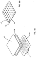
- FIG. 1 is a perspective view of the wound treatment device 10 applied to a patient's skin surface 18.
- a coordinate system 11 is depicted on the patient's skin surface 18 and it defines X,Y and Z directions.
- the attachment portion 12 is formed as an planar rim or flange. This element is attached to the patient's skin with an adhesive and it lies in a first XY plane.
- the transition portion 16 is integrally formed with the attachment portion 12.
- the transition portion 16 rises vertically from the skin surface in the Z direction to connect to the wound treatment portion 14.
- the wound treatment portion 14 has a transparent planar wound cover 20 which allows one to see the wound treatment area 28.
- the wound cover 20 is supported above the first XY plane by a foam ring standoff 15.
- the planar wound cover 20 lies in a second XY plane that is vertically displaced along the Z-axis by the foam ring standoff 15 from the first XY plane.
- the wound cover 20 and foam ring standoff 15 together form the wound treatment portion 14.
- the region over the wound treatment area 28 is called the wound treatment volume 24.
- the wound treatment device 10 has been applied to a patient's skin and is in a relaxed state. In this unstressed state one can see the outer periphery 22 of the attachment portion 12.
- the inner periphery 23 is shown by a crease in the structure where it connects to the transition portion 16.
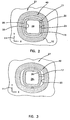
- FIG. 2 and FIG. 3 should be considered together. Together they show the influence of patient motion on the wound treatment device 10. Both FIG. 2 and FIG. 3 are top views of the wound treatment device 10 of FIG. 1 with the various portions of the wound treatment device 10 projected onto the first XY plane.
- FIG. 2 the wound covering is shown in a relaxed and un-stretched state having a nominal total projected area 27.
- the projected wound treatment area 28 is shown at the center of the wound treatment device 10.
- the outline of the foam ring standoff 15 may be seen as the crosshatch area bounded by exterior perimeter 25 of the foam ring standoff 15, and the interior perimeter 26 of the foam ring standoff 15.
- the transition portion projected area 17 is shown in the figure bounded by the inner periphery 23 of the attachment portion 12, and the interior perimeter 26 of the foam ring standoff 15.
- the attachment portion projected area 40 is shown as the cross hatched area bounded by the outer periphery 22 and the inner periphery 23 of the attachment portion 12.
- FIG. 3 shows the wound treatment device 10 stretched along the X-axis by patient motion.
- the overall or total projected area 27 of the wound treatment device 10 has increased.
- the attachment portion projected area 40 has increased slightly as the attachment portion moves with the underlying skin.
- the projected wound enclosure area 28 is essentially unchanged in area since in this embodiment the foam ring standoff 15 is free move against the skin.
- the largest percentage area change occurs in the transition portion projected area 17.
- the transition portion is compliant and pays out material permitting the majority of the total projected area 27 increase to be accommodated primarily by the transition, portion projected area 17.
- FIG. 4 shows a detachable heater 32 positioned for insertion into a pocket formed by pocket cover 21.
- Pocket cover 21 is bonded to the wound cover 20 and is sized to retain the heater 32.
- the foam ring standoff 15 and wound cover 20 serve to stabilize the shape of the wound treatment device while the transition portion accommodates patient motion. Consequently the heater is reliably and comfortably positioned above the wound surface.
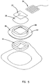
- FIG. 5 is an exploded view of the first embodiment of the wound treatment device 10.
- the attachment portion 12 and transition portion membrane 36 are formed as a unitary composite shell 38.
- the composite shell may be vacuum formed from closed cell polyolefin foams such as Volara-6AS, which is a polyethylene material as sold by Illbruck Inc. of Mpls MN. It should be apparent that many other materials may be substituted within the scope of the invention.
- the foam ring standoff 15 may be die cut from foam sheeting of a reticulated polyurethane foam. The absorbency of the foam as well as its mechanical properties can be tailored to the particular wound treatment application. For example, the foam standoff may be impregnated with a medicament such as an antibiotic; antifungal; or antimicrobial material.
- the wound cover 20 and wound pocket 21 may be made from a thin film of polyethylene.
- the composite shell should be sufficiently self supporting so that when the wound treatment device 10 is removed from its release liner the wound treatment portion 14 is held up or supported by the shaped flexion joint of the transition portion membrane 36, and some effort is required to evert the composite shell and turn it inside out. This behavior defines the self supporting feature which causes the foam ring standoff 15 to lie gently against the skin even when the wound treatment device 10 is upside down. For larger wound coverings it may be desirable to apply a tacky adhesive to the patient contact surface of the standoff.
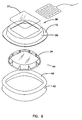
- FIG. 6 is an exploded view of the second embodiment of the wound treatment device 10.
- the attachment portion 12 and transition portion membrane 36 are formed as a unitary composite shell 38.
- the wound treatment volume is formed by a serrated cup standoff 34.
- This member made be made from a more rigid polymeric material such as polyethylene or the like.
- the serrations typified by serration 44 permit the serrated cup to flex and accommodate patient motion.
- This embodiment shows a release liner 42 coupled to the attachment portion 12 of the composite shell 38 with an adhesive 46.In this embodiment the pocket cover 21 is bonded to the composite shell 38.
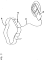
- FIG. 7 depicts a power supply to permit the ambulatory use of the heated versions of the wound treatment device.
- a collection of battery cells may be wired together to form the power supply 48 which may be conveniently attached to a belt 49.
- a suitable cable 50 may be used to conduct power to the heater 32. In many instances it may be desirable to cut off power to the heater if the wound treatment device is collapsed against the wound to prevent overheating of the wound surface.
- FIG. 8 shows a schematic representation of a touch switch which may be incorporated directly into the detachable heater 32.
- the heater 32 includes a continuous resistive heating coil 51.
- a conductive membrane 52 is arranged near the coil 51 so that it may "short out” segments or portions of the coil 51. In use power to the coil is completely turned off by pressure applied to the entire touch sensor 53.
- FIG. 9A shows an exploded version of the heater 32 which incorporates a touch switch of the type described schematically in FIG. 8.
- the switch cover 45 has a conductive membrane which is located over the conductive pattern of the heating coil 51. It is held in position with an adhesive band 54.
- FIG. 9B shows the underside of the switch cover 45 showing a number of discrete insulation bumps typified by bump 47 which serve to space and support the conductive membrane 52 above the heating coil pattern 51. Pressure supplied to the switch cover inactivates the heater coil 51.
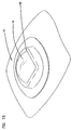
- FIG. 10 shows a an accessory device 55 or cover. This may take the form of a passive heater with a reflective surface facing the wound.
- the accessory device may also take the form of a mapping grid where a grid work of lines is positioned on a transparent card to permit tacking of the wound healing process.
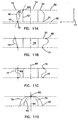
- FIG. 11A through FIG. 11D should be considered together.
- These drawings facilitate a description of connection structures of the invention and represent several alternative connection geometries.
- the transition portion pays out stored material to increase the projected area of the transition portion.
- Each of these drawings represents a mechanical schematic cross section of a wound treatment device 10 in the XZ plane. In each figure the wound covering is in the relaxed state.
- FIG. 11A shows a schematic view of a ring standoff 15 extending from a first plane 56 to a second plane 58.
- the transition portion 16 has a transition portion membrane 60 which is coupled to the attachment portion 12 by a first flexible connection 62 formed at the intersection of the attachment portion 12 and the transition portion 16.
- the transition portion membrane 60 is connected to the treatment portion at a second flexible connection 64 which is formed at the intersection of the transition portion 16 and the wound treatment portion 14.
- the wound treatment portion 14 is generally a cylindrical cup shaped structure defining a wound treatment area on the patient skin surface.
- the minimum interconnection distance 66 is depicted as a dashed line extending from the first flexible connection 62 to the second flexible connection 64.
- the length of this minimum interconnection distance 66 can be used to characterize the "length" of the transition portion membrane 60.
- the length of the transition portion 16 between the first flexible connection 62 and the second flexible connection 64 is greater than the length of the straight line drawn between these points. This relationship is true for many embodiments of the wound treatment device when they are in the relaxed or unstressed position.
- the vertical distance between the first plane 56 and the second plane 58 represents a minimum value for the minimum interconnection distance 66.
- the first flexible connection 62 forms a first perimeter 61 and a second perimeter 63. In the embodiment depicted in FIG. 11A the first perimeter 61 is larger than the second perimeter 63.
- FIG. 11B is a mechanical schematic diagram which represents a cross section of another embodiment of the wound treatment device 10 with an alternate connection geometry.
- the wound cover 20 extends radially beyond the wound treatment volume 24 so that the second perimeter 68 is greater than the first perimeter 71.
- This generates a reflex transition portion 74 construction which may be adopted to increase the "length" and amount of material in the reflex transition portion 74.
- FIG. 11C shows a construction where the first perimeter 76 and the second perimeter 78 have approximately the same value and are both concentric with the axis 90. This construction can produce an undulated transition portion 77. Once again the length of the undulated transition portion 77 exceeds the length of the line 65 between the first perimeter 78 and the second perimeter 76.
- FIG. 11D shows a hemispheric shell 70 as the wound treatment portion 14.
- the second perimeter 80 is a single attachment point generally concentric with the axis 90.
- the first perimeter 81 has a length which greatly exceeds the second perimeter 80 length.
- This construction forms a hemispheric transition portion 79 which has a length which exceeds the linear distance between the second perimeter 80 and the first perimeter 81 along the line 85.
- the transition portion from a resilient material which is generally self-supporting, yet sufficiently flexible so that it acts as a compliant hinge mechanism. This flexibility prevents the transfer of shearing force from the wound treatment portion 14 to the attachment portion 12 of the wound treatment device 10 and visa versa.
- the transition portion of the wound treatment device 10 forms a shaped flexion joint or formed expansion joint which stores "material” in a pleat, convolution or bellows or the like. This type of structure provides a means for expanding the size of the transition portion to minimize the transfer of forces from the attachment portion 12 to the wound treatment portion 14.
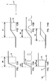
- FIG. 12A through FIG. 14B should be considered together.
- the standoff structure reduces in height to result in the increased transition portion area during the stretching of the wound treatment device.
- FIG. 12A shows a part of a wound treatment device having a foam ring standoff 15 which is shown in the unstressed or relaxed state.
- the transition portion projected area 17 is proportional to dimension 88.
- FIG. 12B the wound treatment device has been stretched and the height of the foam ring standoff 15 is reduced in the Z direction which has increased the transition portion projected area as represented by dimension 91.
- FIG. 13A shows a part of a wound treatment device having a serrated cup standoff 34 which is shown in the unstressed or relaxed state.
- the transition portion projected area 17 is proportional to dimension 98.
- FIG. 13B the wound treatment device has been stretched and the height of the serrated cup standoff 34 is reduced in the Z direction.
- the serrated wall sections splay out to permit the height reduction which has increased the transition portion projected area as represented by dimension 99.
- FIG. 14A shows a part of a wound treatment device having a foam ring standoff 15 which is shown in the unstressed or relaxed state. However in this construction the attachment portion 12 and transition portion membrane 96 lie entirely in the first plane 56. In this instance the transition portion projected area 17 is proportional to dimension 94.
- FIG. 14B the wound treatment device has been stretched and the height of the foam ring standoff 15 is reduced in the Z direction. This height reduction which has increased the transition portion projected area is represented by dimension 92.
- FIG. 15 shows a version of the wound treatment device 10 which includes a dome shaped or hemispheric wound cover 19. At least a portion of this device lies in the second XY plane 58.
- FIG. 16 shows a version of the wound treatment device 10 which includes a releasable and resealable wound cover 20.
- the wound cover 20 may have a tab 29 located at the periphery of the wound cover 20.
- a reusable adhesive 30 may be applied to the periphery of the wound cover 20 as well to allow the cover to be releasable attached to the standoff 15 structure or composite shell 38.
- FIG. 17A shows a releasable wound cover incorporating a heater pocket cover 21.
- the resealable wound cover 20 and pocket cover 21 forms a space for the heater 32.
- FIG. 17B shows that one advantage of the resealable and removable construction is that the opening for the heater may be shifted without removing or repositioning the wound treatment device 10.
- FIG. 17C shows a wedge shaped wound treatment device 10.
- a line 31 in the XY plane 11 of the attachment portion 12 intersects with a line 33 which lies across the top of the standoff 15. These tow lines may meet a point 35 in space as seen in the drawing.
- FIG. 18 shows a an alternate method of attaching the planar heater 32 to the wound cover 20.
- the heater has a hook or loop material 39 attached to the edge of the heater 32 and the complimentary loop or hook material 37 is attached tot he composite shell 38.
- the wound cover need not be accessible to reorient the heater 32. It should be appreciated that an adhesive may be used to attach the heater as well.
- FIG. 19A is a perspective view of an alternate version of the wound treatment device with a heater.
- the heater 83 is dome shaped to conform to the shape of the wound cover 84.
- complimentary loop and hook material 37 and 39 may be used for releasable attachment to the wound treatment device.
- FIG. 19B is a perspective view of an alternate version of the wound treatment device with a heater attached to the wound treatment device with an adhesive or the like.
- a resistive heater grid is formed in the cover to generate heat in response to electrical energy applied trough leads 50.
- FIG. 20A is a perspective view of an alternate version of the wound treatment device with a dome shaped heater 86.
- the heater 86 has a collection of independent parallel connected resistive loops typified by loop 87. In use the resistance of the loop is selected to ensure that the radiated heat is uniform as measured at the wound surface.
- FIG. 20B is a perspective view of an alternate version of the wound treatment device with a dome shaped heater 86 attached to the wound treatment device 10.
- FIG. 21A is a perspective view of an alternate version of the wound treatment device with a dome shaped heater 89.
- a heater wire is coiled to provide the heater element.
- FIG. 21B is a perspective view of an alternate version of the wound treatment device with a dome shaped heater 89.
- the coil spacing indicated by dimension 87 can be adjusted to provide uniform heating of the wound area.
- FIG. 22A is a perspective view of a wound treatment device 10 having two complimentary pockets shown as pocket 97 and pocket 95 which cooperate with tab 83 and tab 75 formed on the heater 32.
- FIG. 22B is a perspective view which shows tab 75 and tab 83 inserted into the complimentary pockets 95 and pocket 97 to position and retain a planar heater structure.
Abstract
Description
- The invention relates to a wound cover which may be attachable to a wound treatment device for covering and in some applications heating skin lesions, surgical wounds and the like.
- Together the wound treatment device, the wound cover and optionally a detachable wound heater provide a non-contact wound treatment volume over the wound area.
- One traditional method of treating a wound involves the placement of a sterile gauze over the wound area and holding the gauze in place with an adhesive tape. This type of wound dressing has numerous shortcomings. The wound is not fully isolated from the air and can exchange bacteria with the environment. The gauze can adhere to the wound itself interfering with the healing process which is undesirable. This traditional form of bandage does not control the thermal environment of the wound which is also undesirable.
- Although some forms of wound heaters and non-contact wound coverings are known from Veilhan Fr. 1,527,887 (1969) they are not generally accepted for several reasons. For example, wound coverings which include a rigid enclosure forming a cavity that covers the wound are usually adhesively attached to the skin of the patient with a relatively inelastic material. As a result the wound covering is unable to accommodate patient motion. Consequently patient motion will cause the rigid wound covering to "peel-off" of the patient's skin. The traditional solution to this problem has been to use a more aggressive adhesive tape or the like to more firmly attach the wound covering to the skin. This solution to the problem results in an uncomfortable bandage.
- The traditional wound covering does not permit close control over the temperature of the wound area. Prior art heated bandages which rely on a non-contact enclosure may use point source type heaters which result in variations in radiant heat flux depending on the location of the heater within the enclosure. Therefore there is a need for a non-contact bandage which can be used to control the environment of the wound and which may be reliably and comfortably attached to the skin.
- The
wound treatment device 10 of the present invention has an upper wound covering surface displaced above the patient's skin surface, and an attachment surface lying generally in the plane of the patient's skin. Together these two surfaces define an enclosed non-contact volume over the wound treatment site. - The
wound treatment device 10 may be divided into three separate parts for the purpose of description. These parts are anattachment portion 12, awound treatment portion 14, and atransition portion 16. Each portion is designed to serve a separate function. - The
attachment portion 12 is used to connect thewound treatment device 10 to the skin of a patient. Theattachment portion 12 will usually be formed as an annular attachment rim. An adhesive will typically be placed on the attachment rim to couple thewound treatment device 10 to the patient. Theattachment portion 12 lies near the patient's skin and defines a so called first plane. - The
wound treatment portion 14 of thewound treatment device 10 is illustratively an assembly which includes astandoff 15 which rises above the patient's skin surface, and awound cover 20 which spans the open portion of thestandoff 15. Thestandoff 15 helps to define the vertical extent or dimension of thewound treatment device 10 and helps to define the location of a second plane which is used to describe the geometry of the device. Thus thewound treatment portion 14 includes astandoff 15 and awound cover 20 which together define both awound treatment volume 24 and awound treatment area 26. - The
wound treatment volume 24 is located over the surface of the wound. The atmosphere in thiswound treatment volume 24 can be controlled by thewound treatment device 10. - In use the
wound treatment area 26 is defined on thepatient surface 18 under thewound treatment portion 14, and will typically be centered over the lesion or wound. - The
transition portion 16 connects theattachment portion 12 to thewound treatment portion 14. Thistransition portion 16 improves the comfort and utility of the wound treatment device when the patient moves and stretches thewound treatment device 10. This stretching causes the total projected area of thewound treatment device 10 to increase and the shape of thewound treatment device 10 to change. In practice, the bulk of the patient motion is accommodated by the compliance of thetransition portion 16. As a consequence, the transition portion projectedarea 17 increases. The standoff ofwound treatment portion 14 rests gently on the patient's skin and it may twist to accommodate patient motion thus producing a device which conforms to the contour of the patient's body. However since the standoff can slide along the patient's skin there is no substantial change in the projectedwound treatment area 28 due to patient motion. During patient motion theattachment portion 12 remains affixed to the surface of the patient and is easily deformed by body motion because of its relatively small area. Consequently the attachment portion projectedarea 40 may undergo a slight increase in area as theattachment portion 12 moves with the underlying skin. Throughout this motion the second shaped surface is supported above the patient's skin surface and can be used to support adetachable heater 32 which can heat the wound surface. A switch may also be provided to reduce power supplied to thewound treatment device 10 if the device is crushed in to contact with the wound. - The various figures of the drawing depict illustrative and exemplary forms of the
wound treatment device 10. Throughout the several views, identical reference characters represent similar or equivalent structures wherein: - FIG. 1 is a perspective view of a first embodiment of the wound treatment device;
- FIG. 2 is a schematic view of projected areas;
- FIG. 3 is a schematic view of projected areas;
- FIG. 4 is a perspective view of a detachable heater in combination with a first embodiment of the wound treatment device;
- FIG. 5 is an exploded view of the first embodiment of the wound treatment device;
- FIG. 6 is an exploded view of the second embodiment of the wound treatment device;
- FIG. 7 is a perspective view of a heater system;
- FIG. 8 is an electrical schematic of a pressure sensitive switch for a heater system;
- FIG. 9A is an exploded view of a pressure sensitive switch incorporated into a wound treatment device;
- FIG. 9B is a view of a portion of the pressure sensitive switch;
- FIG. 10 is a perspective view of a passive heater embodiment of the wound treatment device;
- FIG. 11A is a schematic drawing depicting an alternate geometry for the transition portion;
- FIG. 11B is a schematic drawing depicting an alternate geometry for the transition portion;
- FIG. 11C is a schematic drawing depicting an alternate geometry for the transition portion;
- FIG. 11D is a schematic drawing depicting an alternate geometry for the transition portion;
- FIG. 12A is a schematic drawing depicting functional relationships between several elements of the invention;
- FIG. 12B is a schematic drawing depicting functional relationships between several elements of the invention;
- FIG. 13A is a schematic drawing depicting functional relationships between several elements of the invention;
- FIG. 13B is a schematic drawing depicting functional relationships between several elements of the invention;
- FIG. 14A is a schematic drawing depicting functional relationships between several elements of the invention;
- FIG. 14B is a schematic drawing depicting functional relationships between several elements of the invention;
- FIG. 15 is a perspective view of an alternate version of the wound treatment device;
- FIG. 16 is a perspective view of an alternate version of the wound treatment device;
- FIG. 17A is a perspective view of an alternate version of the wound treatment device with a heater;
- FIG. 17B is a perspective view of an alternate version of the wound treatment device with a heater;
- FIG. 17C is a perspective view of an alternate version of the wound treatment device;
- FIG. 18 is a perspective view of an alternate version of the wound treatment device with a heater;
- FIG. 19A is a perspective view of an alternate version of the wound treatment device with a heater;
- FIG. 19B is a perspective view of an alternate version of the wound treatment device with a heater;
- FIG. 20A is a perspective view of an alternate version of the wound treatment device with a heater;
- FIG. 20B is a perspective view of an alternate version of the wound treatment device with a heater;
- FIG. 21A is a perspective view of an alternate version of the wound treatment device with a heater;
- FIG. 21B is a perspective view of an alternate version of the wound treatment device with a heater;
- FIG. 22A is a perspective view of an alternate version of the wound treatment device with a heater; and
- FIG. 22B is a perspective view of an alternate version of the wound treatment device with a heater.
-
- FIG. 1 is a perspective view of the
wound treatment device 10 applied to a patient'sskin surface 18. A coordinatesystem 11 is depicted on the patient'sskin surface 18 and it defines X,Y and Z directions. Theattachment portion 12 is formed as an planar rim or flange. This element is attached to the patient's skin with an adhesive and it lies in a first XY plane. In this first embodiment of thewound treatment device 10 thetransition portion 16 is integrally formed with theattachment portion 12. Thetransition portion 16 rises vertically from the skin surface in the Z direction to connect to thewound treatment portion 14. In this embodiment thewound treatment portion 14 has a transparent planar wound cover 20 which allows one to see thewound treatment area 28. The wound cover 20 is supported above the first XY plane by afoam ring standoff 15. The planar wound cover 20 lies in a second XY plane that is vertically displaced along the Z-axis by thefoam ring standoff 15 from the first XY plane. The wound cover 20 andfoam ring standoff 15 together form thewound treatment portion 14. The region over thewound treatment area 28 is called thewound treatment volume 24. - In this figure the
wound treatment device 10 has been applied to a patient's skin and is in a relaxed state. In this unstressed state one can see theouter periphery 22 of theattachment portion 12. Theinner periphery 23 is shown by a crease in the structure where it connects to thetransition portion 16. - FIG. 2 and FIG. 3 should be considered together. Together they show the influence of patient motion on the
wound treatment device 10. Both FIG. 2 and FIG. 3 are top views of thewound treatment device 10 of FIG. 1 with the various portions of thewound treatment device 10 projected onto the first XY plane. - In FIG. 2 the wound covering is shown in a relaxed and un-stretched state having a nominal total projected
area 27. The projected woundtreatment area 28 is shown at the center of thewound treatment device 10. The outline of thefoam ring standoff 15 may be seen as the crosshatch area bounded byexterior perimeter 25 of thefoam ring standoff 15, and theinterior perimeter 26 of thefoam ring standoff 15. The transition portion projectedarea 17 is shown in the figure bounded by theinner periphery 23 of theattachment portion 12, and theinterior perimeter 26 of thefoam ring standoff 15. The attachment portion projectedarea 40 is shown as the cross hatched area bounded by theouter periphery 22 and theinner periphery 23 of theattachment portion 12. - FIG. 3 shows the
wound treatment device 10 stretched along the X-axis by patient motion. In comparison to FIG. 2 the overall or total projectedarea 27 of thewound treatment device 10 has increased. The attachment portion projectedarea 40 has increased slightly as the attachment portion moves with the underlying skin. The projectedwound enclosure area 28 is essentially unchanged in area since in this embodiment thefoam ring standoff 15 is free move against the skin. The largest percentage area change occurs in the transition portion projectedarea 17. As thewound treatment device 10 deforms in response to patient motion the transition portion is compliant and pays out material permitting the majority of the total projectedarea 27 increase to be accommodated primarily by the transition, portion projectedarea 17. - FIG. 4 shows a
detachable heater 32 positioned for insertion into a pocket formed bypocket cover 21.Pocket cover 21 is bonded to thewound cover 20 and is sized to retain theheater 32. Thefoam ring standoff 15 and woundcover 20 serve to stabilize the shape of the wound treatment device while the transition portion accommodates patient motion. Consequently the heater is reliably and comfortably positioned above the wound surface. In general it is desirable to use aplanar heater 32 which has a constant heat output per unit area. This form of heater results in a more uniform flux of radiant energy applied to the wound. And the amount of heat supplied to the wound area is largely independent of the height of theheater 32 above the wound surface. - FIG. 5 is an exploded view of the first embodiment of the
wound treatment device 10. Theattachment portion 12 andtransition portion membrane 36 are formed as a unitarycomposite shell 38. The composite shell may be vacuum formed from closed cell polyolefin foams such as Volara-6AS, which is a polyethylene material as sold by Illbruck Inc. of Mpls MN. It should be apparent that many other materials may be substituted within the scope of the invention. Thefoam ring standoff 15 may be die cut from foam sheeting of a reticulated polyurethane foam. The absorbency of the foam as well as its mechanical properties can be tailored to the particular wound treatment application. For example, the foam standoff may be impregnated with a medicament such as an antibiotic; antifungal; or antimicrobial material. It may also be desirable to supply a deodorant material or nitric oxide releasing material from the foam standoff. The wound cover 20 and woundpocket 21 may be made from a thin film of polyethylene. In general, the composite shell should be sufficiently self supporting so that when thewound treatment device 10 is removed from its release liner thewound treatment portion 14 is held up or supported by the shaped flexion joint of thetransition portion membrane 36, and some effort is required to evert the composite shell and turn it inside out. This behavior defines the self supporting feature which causes thefoam ring standoff 15 to lie gently against the skin even when thewound treatment device 10 is upside down. For larger wound coverings it may be desirable to apply a tacky adhesive to the patient contact surface of the standoff. - FIG. 6 is an exploded view of the second embodiment of the
wound treatment device 10. Theattachment portion 12 andtransition portion membrane 36 are formed as a unitarycomposite shell 38. In this embodiment the wound treatment volume is formed by aserrated cup standoff 34. This member made be made from a more rigid polymeric material such as polyethylene or the like. The serrations typified byserration 44 permit the serrated cup to flex and accommodate patient motion. This embodiment shows arelease liner 42 coupled to theattachment portion 12 of thecomposite shell 38 with an adhesive 46.In this embodiment thepocket cover 21 is bonded to thecomposite shell 38. - FIG. 7 depicts a power supply to permit the ambulatory use of the heated versions of the wound treatment device. A collection of battery cells may be wired together to form the
power supply 48 which may be conveniently attached to abelt 49. Asuitable cable 50 may be used to conduct power to theheater 32. In many instances it may be desirable to cut off power to the heater if the wound treatment device is collapsed against the wound to prevent overheating of the wound surface. - FIG. 8 shows a schematic representation of a touch switch which may be incorporated directly into the
detachable heater 32. Theheater 32 includes a continuousresistive heating coil 51. Aconductive membrane 52 is arranged near thecoil 51 so that it may "short out" segments or portions of thecoil 51. In use power to the coil is completely turned off by pressure applied to theentire touch sensor 53. - FIG. 9A shows an exploded version of the
heater 32 which incorporates a touch switch of the type described schematically in FIG. 8. Theswitch cover 45 has a conductive membrane which is located over the conductive pattern of theheating coil 51. It is held in position with anadhesive band 54. FIG. 9B shows the underside of theswitch cover 45 showing a number of discrete insulation bumps typified bybump 47 which serve to space and support theconductive membrane 52 above theheating coil pattern 51. Pressure supplied to the switch cover inactivates theheater coil 51. - FIG. 10 shows a an
accessory device 55 or cover. This may take the form of a passive heater with a reflective surface facing the wound. The accessory device may also take the form of a mapping grid where a grid work of lines is positioned on a transparent card to permit tacking of the wound healing process. - FIG. 11A through FIG. 11D should be considered together. These drawings facilitate a description of connection structures of the invention and represent several alternative connection geometries. In general to accommodate patient motion the transition portion pays out stored material to increase the projected area of the transition portion. Each of these drawings represents a mechanical schematic cross section of a
wound treatment device 10 in the XZ plane. In each figure the wound covering is in the relaxed state. - FIG. 11A shows a schematic view of a
ring standoff 15 extending from afirst plane 56 to asecond plane 58. Thetransition portion 16 has atransition portion membrane 60 which is coupled to theattachment portion 12 by a firstflexible connection 62 formed at the intersection of theattachment portion 12 and thetransition portion 16. Thetransition portion membrane 60 is connected to the treatment portion at a secondflexible connection 64 which is formed at the intersection of thetransition portion 16 and thewound treatment portion 14. Thewound treatment portion 14 is generally a cylindrical cup shaped structure defining a wound treatment area on the patient skin surface. Theminimum interconnection distance 66 is depicted as a dashed line extending from the firstflexible connection 62 to the secondflexible connection 64. The length of thisminimum interconnection distance 66 can be used to characterize the "length" of thetransition portion membrane 60. For many embodiments of the invention the length of thetransition portion 16 between the firstflexible connection 62 and the secondflexible connection 64 is greater than the length of the straight line drawn between these points. This relationship is true for many embodiments of the wound treatment device when they are in the relaxed or unstressed position. It should be noted that the vertical distance between thefirst plane 56 and thesecond plane 58 represents a minimum value for theminimum interconnection distance 66. In the XY plane the firstflexible connection 62 forms afirst perimeter 61 and asecond perimeter 63. In the embodiment depicted in FIG. 11A thefirst perimeter 61 is larger than thesecond perimeter 63. - FIG. 11B is a mechanical schematic diagram which represents a cross section of another embodiment of the
wound treatment device 10 with an alternate connection geometry. In this drawing thewound cover 20 extends radially beyond thewound treatment volume 24 so that thesecond perimeter 68 is greater than thefirst perimeter 71. This generates areflex transition portion 74 construction which may be adopted to increase the "length" and amount of material in thereflex transition portion 74. - FIG. 11C shows a construction where the
first perimeter 76 and thesecond perimeter 78 have approximately the same value and are both concentric with theaxis 90. This construction can produce an undulatedtransition portion 77. Once again the length of the undulatedtransition portion 77 exceeds the length of theline 65 between thefirst perimeter 78 and thesecond perimeter 76. - FIG. 11D shows a
hemispheric shell 70 as thewound treatment portion 14. In this embodiment thesecond perimeter 80 is a single attachment point generally concentric with theaxis 90. In this embodiment thefirst perimeter 81 has a length which greatly exceeds thesecond perimeter 80 length. This construction forms ahemispheric transition portion 79 which has a length which exceeds the linear distance between thesecond perimeter 80 and thefirst perimeter 81 along theline 85. - Although the various geometries vary in detail it is preferred to form the transition portion from a resilient material which is generally self-supporting, yet sufficiently flexible so that it acts as a compliant hinge mechanism. This flexibility prevents the transfer of shearing force from the
wound treatment portion 14 to theattachment portion 12 of thewound treatment device 10 and visa versa. With the geometries set forth in FIG. 11A through FIG. 11D the transition portion of thewound treatment device 10 forms a shaped flexion joint or formed expansion joint which stores "material" in a pleat, convolution or bellows or the like. This type of structure provides a means for expanding the size of the transition portion to minimize the transfer of forces from theattachment portion 12 to thewound treatment portion 14. - FIG. 12A through FIG. 14B should be considered together. In these embodiments of the invention the standoff structure reduces in height to result in the increased transition portion area during the stretching of the wound treatment device.
- FIG. 12A shows a part of a wound treatment device having a
foam ring standoff 15 which is shown in the unstressed or relaxed state. In this instance the transition portion projectedarea 17 is proportional todimension 88. In FIG. 12B the wound treatment device has been stretched and the height of thefoam ring standoff 15 is reduced in the Z direction which has increased the transition portion projected area as represented bydimension 91. - FIG. 13A shows a part of a wound treatment device having a
serrated cup standoff 34 which is shown in the unstressed or relaxed state. In this instance the transition portion projectedarea 17 is proportional todimension 98. In FIG. 13B the wound treatment device has been stretched and the height of theserrated cup standoff 34 is reduced in the Z direction. The serrated wall sections splay out to permit the height reduction which has increased the transition portion projected area as represented bydimension 99. - FIG. 14A shows a part of a wound treatment device having a
foam ring standoff 15 which is shown in the unstressed or relaxed state. However in this construction theattachment portion 12 andtransition portion membrane 96 lie entirely in thefirst plane 56. In this instance the transition portion projectedarea 17 is proportional todimension 94. In FIG. 14B the wound treatment device has been stretched and the height of thefoam ring standoff 15 is reduced in the Z direction. This height reduction which has increased the transition portion projected area is represented bydimension 92. - FIG. 15 shows a version of the
wound treatment device 10 which includes a dome shaped orhemispheric wound cover 19. At least a portion of this device lies in thesecond XY plane 58. - FIG. 16 shows a version of the
wound treatment device 10 which includes a releasable andresealable wound cover 20. To facilitate access to the wound thewound cover 20 may have atab 29 located at the periphery of thewound cover 20. In general a reusable adhesive 30 may be applied to the periphery of the wound cover 20 as well to allow the cover to be releasable attached to thestandoff 15 structure orcomposite shell 38. - FIG. 17A shows a releasable wound cover incorporating a
heater pocket cover 21. In use theresealable wound cover 20 and pocket cover 21 forms a space for theheater 32. - FIG. 17B shows that one advantage of the resealable and removable construction is that the opening for the heater may be shifted without removing or repositioning the
wound treatment device 10. - FIG. 17C shows a wedge shaped
wound treatment device 10. Aline 31 in theXY plane 11 of theattachment portion 12 intersects with aline 33 which lies across the top of thestandoff 15. These tow lines may meet apoint 35 in space as seen in the drawing. - FIG. 18 shows a an alternate method of attaching the
planar heater 32 to thewound cover 20. In this embodiment the heater has a hook orloop material 39 attached to the edge of theheater 32 and the complimentary loop orhook material 37 is attached tot hecomposite shell 38. In this embodiment the wound cover need not be accessible to reorient theheater 32. It should be appreciated that an adhesive may be used to attach the heater as well. - FIG. 19A is a perspective view of an alternate version of the wound treatment device with a heater. In this embodiment the
heater 83 is dome shaped to conform to the shape of thewound cover 84. complimentary loop andhook material - FIG. 19B is a perspective view of an alternate version of the wound treatment device with a heater attached to the wound treatment device with an adhesive or the like. In this embodiment a resistive heater grid is formed in the cover to generate heat in response to electrical energy applied trough leads 50.
- FIG. 20A is a perspective view of an alternate version of the wound treatment device with a dome shaped
heater 86. In this embodiment theheater 86 has a collection of independent parallel connected resistive loops typified byloop 87. In use the resistance of the loop is selected to ensure that the radiated heat is uniform as measured at the wound surface. - FIG. 20B is a perspective view of an alternate version of the wound treatment device with a dome shaped
heater 86 attached to thewound treatment device 10. - FIG. 21A is a perspective view of an alternate version of the wound treatment device with a dome shaped
heater 89. In this embodiment a heater wire is coiled to provide the heater element. - FIG. 21B is a perspective view of an alternate version of the wound treatment device with a dome shaped
heater 89. In use the coil spacing indicated bydimension 87 can be adjusted to provide uniform heating of the wound area. - FIG. 22A is a perspective view of a
wound treatment device 10 having two complimentary pockets shown aspocket 97 andpocket 95 which cooperate withtab 83 and tab 75 formed on theheater 32. - FIG. 22B is a perspective view which shows tab 75 and
tab 83 inserted into thecomplimentary pockets 95 andpocket 97 to position and retain a planar heater structure. - Having thus described the invention it should be apparent that numerous changes may be made without departing from the scope of the invention as defined by the claims.
Claims (10)
- A wound cover for use with a wound treatment device having an attachment portion for attachment to a patient's skin and a standoff extending from a first plane to a second plane defining a non-contact wound treatment area (24) characterised in that the wound covering (20) is adapted to span at least the wound treatment area such that the wound treatment area is closed, and the wound covering (20) is attachable to the wound treatment device.
- A wound cover as claimed in claim 1 wherein the wound cover is releasably attachable to the wound treatment portion by means selected from an adhesive, a reusable adhesive, and hook and loop material.
- A wound cover as claimed in claim 1 or claim 2 which includes a grip tab, for facilitating removal and repositioning of the wound cover to permit access to the wound area.
- A wound cover as claimed in any of claims 1 to 3 which is a heater.
- A wound cover as claimed in any of claims 1 to 4 comprising a second layer, the wound cover and the second layer together defining a pocket, for receiving and retaining a heater or a heat reflector.
- A wound cover as claimed in any of claims 1 to 3 comprising means to releasably attach a heater to the wound cover.
- A wound cover as claimed in any of claims 1 to 3 with a resistive heater grid formed therein.
- A wound cover as claimed in any preceding claim which is transparent to allow one to see the wound treatment area.
- A wound cover as claimed in any preceding claim comprising a thin film of polyethylene.
- A wound cover as claimed in any preceding claim which is dome-shaped or hemispherical.
Applications Claiming Priority (3)
| Application Number | Priority Date | Filing Date | Title |
|---|---|---|---|
| US08/342,741 US5817145A (en) | 1994-11-21 | 1994-11-21 | Wound treatment device |
| US342741 | 1994-11-21 | ||
| EP95940794A EP0793467B1 (en) | 1994-11-21 | 1995-11-21 | Wound treatment device for attachment to skin |
Related Parent Applications (1)
| Application Number | Title | Priority Date | Filing Date |
|---|---|---|---|
| EP95940794A Division EP0793467B1 (en) | 1994-11-21 | 1995-11-21 | Wound treatment device for attachment to skin |
Publications (3)
| Publication Number | Publication Date |
|---|---|
| EP0982015A2 true EP0982015A2 (en) | 2000-03-01 |
| EP0982015A3 EP0982015A3 (en) | 2000-03-15 |
| EP0982015B1 EP0982015B1 (en) | 2006-08-30 |
Family
ID=23343082
Family Applications (2)
| Application Number | Title | Priority Date | Filing Date |
|---|---|---|---|
| EP95940794A Expired - Lifetime EP0793467B1 (en) | 1994-11-21 | 1995-11-21 | Wound treatment device for attachment to skin |
| EP99121265A Expired - Lifetime EP0982015B1 (en) | 1994-11-21 | 1995-11-21 | A wound cover |
Family Applications Before (1)
| Application Number | Title | Priority Date | Filing Date |
|---|---|---|---|
| EP95940794A Expired - Lifetime EP0793467B1 (en) | 1994-11-21 | 1995-11-21 | Wound treatment device for attachment to skin |
Country Status (7)
| Country | Link |
|---|---|
| US (8) | US5817145A (en) |
| EP (2) | EP0793467B1 (en) |
| JP (1) | JP3918158B2 (en) |
| AT (2) | ATE337767T1 (en) |
| CA (1) | CA2204159C (en) |
| DE (2) | DE69533989T2 (en) |
| WO (1) | WO1996015745A2 (en) |
Cited By (14)
| Publication number | Priority date | Publication date | Assignee | Title |
|---|---|---|---|---|
| WO2002089718A2 (en) * | 2001-05-10 | 2002-11-14 | Augustine Medical, Inc. | Minimal contact wound treatment device |
| US9642750B2 (en) | 2009-12-22 | 2017-05-09 | Smith & Nephew, Inc. | Apparatuses and methods for negative pressure wound therapy |
| US9801985B2 (en) | 2007-12-06 | 2017-10-31 | Smith & Nephew Plc | Apparatus for topical negative pressure therapy |
| US9844473B2 (en) | 2002-10-28 | 2017-12-19 | Smith & Nephew Plc | Apparatus for aspirating, irrigating and cleansing wounds |
| US9907703B2 (en) | 2012-05-23 | 2018-03-06 | Smith & Nephew Plc | Apparatuses and methods for negative pressure wound therapy |
| US9956389B2 (en) | 2010-12-22 | 2018-05-01 | Smith & Nephew, Inc. | Apparatuses and methods for negative pressure wound therapy |
| CN108113802A (en) * | 2018-02-10 | 2018-06-05 | 孙秀琴 | A kind of separable wound and newborn's care device |
| US10350339B2 (en) | 2004-04-05 | 2019-07-16 | Smith & Nephew, Inc. | Flexible reduced pressure treatment appliance |
| US10406036B2 (en) | 2009-06-18 | 2019-09-10 | Smith & Nephew, Inc. | Apparatus for vacuum bridging and/or exudate collection |
| US10667955B2 (en) | 2012-08-01 | 2020-06-02 | Smith & Nephew Plc | Wound dressing and method of treatment |
| USRE48117E1 (en) | 2010-05-07 | 2020-07-28 | Smith & Nephew, Inc. | Apparatuses and methods for negative pressure wound therapy |
| US11058587B2 (en) | 2010-04-27 | 2021-07-13 | Smith & Nephew Plc | Wound dressing and method of use |
| US11154649B2 (en) | 2015-05-18 | 2021-10-26 | Smith & Nephew Plc | Fluidic connector for negative pressure wound therapy |
| US11439741B2 (en) | 2013-05-10 | 2022-09-13 | Smith & Nephew Plc | Fluidic connector for irrigation and aspiration of wounds |
Families Citing this family (187)
| Publication number | Priority date | Publication date | Assignee | Title |
|---|---|---|---|---|
| US6406448B1 (en) | 1992-06-19 | 2002-06-18 | Augustine Medical, Inc. | Normothermic heater covering for tissue treatment |
| US5947914A (en) * | 1995-02-21 | 1999-09-07 | Augustine Medical, Inc. | Wound covering |
| US5986163A (en) * | 1992-06-19 | 1999-11-16 | Augustine Medical, Inc. | Normothermic heater wound covering |
| US5954680A (en) | 1992-06-19 | 1999-09-21 | Augustine Medical, Inc. | Near hyperthermic heater wound covering |
| US7928281B2 (en) | 1992-06-19 | 2011-04-19 | Arizant Technologies Llc | Wound covering |
| US6465708B1 (en) | 1992-06-19 | 2002-10-15 | Augustine Medical, Inc. | Covering |
| US5964723A (en) * | 1992-06-19 | 1999-10-12 | Augustine Medical, Inc. | Normothermic tissue heating wound covering |
| US7537605B2 (en) * | 1993-10-04 | 2009-05-26 | Huan-Chen Li | Medical device for treating skin itch and rash |
| US6110197A (en) | 1994-11-21 | 2000-08-29 | Augustine Medical, Inc. | Flexible non-contact wound treatment device with a single joint |
| US5817145A (en) * | 1994-11-21 | 1998-10-06 | Augustine Medical, Inc. | Wound treatment device |
| US6093160A (en) | 1994-11-21 | 2000-07-25 | Augustine Medical, Inc. | Flexible non-contact wound treatment device |
| WO1998026838A1 (en) * | 1996-12-18 | 1998-06-25 | Vidacare International, Inc. | Surgical healing mesh |
| IL120910A (en) * | 1997-05-26 | 2004-01-04 | Lrr & D Ltd | Multipurpose dynamic occlusive dressing |
| US6420623B2 (en) | 1998-04-06 | 2002-07-16 | Augustine Medical, Inc. | Bandage for autolytic wound debridement |
| US6095992A (en) * | 1998-04-06 | 2000-08-01 | Augustine Medical, Inc. | Wound treatment apparatus for normothermic treatment of wounds |
| US6235047B1 (en) * | 1998-04-06 | 2001-05-22 | Augustine Medical, Inc. | Wound treatment apparatus with a heater, a heat conductive bandage, and heat-spreading means acting between the heater and bandage |
| US6071304A (en) * | 1998-04-06 | 2000-06-06 | Augustine Medical, Inc. | Wound treatment apparatus with a heater adhesively joined to a bandage |
| US6143945A (en) * | 1998-04-06 | 2000-11-07 | Augustine Medical, Inc. | Bandage for autolytic wound debridement |
| US6213965B1 (en) * | 1998-04-06 | 2001-04-10 | Augustine Medical, Inc. | Wound treatment apparatus with infrared absorptive wound cover |
| TW406018B (en) * | 1998-05-21 | 2000-09-21 | Elan Corp Plc | Improved adhesive system for medical devices |
| US6527979B2 (en) | 1999-08-27 | 2003-03-04 | Corazon Technologies, Inc. | Catheter systems and methods for their use in the treatment of calcified vascular occlusions |
| US6458109B1 (en) | 1998-08-07 | 2002-10-01 | Hill-Rom Services, Inc. | Wound treatment apparatus |
| EP1092404A1 (en) | 1999-10-11 | 2001-04-18 | Eurovita AG | Wound covering |
| US7087807B2 (en) * | 1999-11-10 | 2006-08-08 | Arizant Technologies, Llc | Tissue treatment device for an extremity |
| US6800074B2 (en) | 1999-11-29 | 2004-10-05 | Hill-Rom Services, Inc. | Wound treatment apparatus |
| US6824533B2 (en) | 2000-11-29 | 2004-11-30 | Hill-Rom Services, Inc. | Wound treatment apparatus |
| US6764462B2 (en) | 2000-11-29 | 2004-07-20 | Hill-Rom Services Inc. | Wound treatment apparatus |
| US6528696B1 (en) * | 2000-01-11 | 2003-03-04 | Christine M. Ireland | Pliable contact bandage |
| US20010049546A1 (en) * | 2000-02-08 | 2001-12-06 | Israel Dvoretzky | Multi-purpose drug and heat therapy treatment system |
| JP2004509658A (en) | 2000-05-22 | 2004-04-02 | コフィー,アーサー,シー. | Combination of small intestinal submucosa and vacuum bandage and its use |
| EP3006057A1 (en) | 2000-08-24 | 2016-04-13 | Cordis Corporation | Fluid delivery systems for delivering fluids to multi-lumen catheters |
| US6416534B1 (en) | 2000-10-10 | 2002-07-09 | Sunbeam Products, Inc. | Portable heating pad with removable heat pad, removable gel pack and pressure bladder |
| US6855135B2 (en) | 2000-11-29 | 2005-02-15 | Hill-Rom Services, Inc. | Vacuum therapy and cleansing dressing for wounds |
| US6685681B2 (en) | 2000-11-29 | 2004-02-03 | Hill-Rom Services, Inc. | Vacuum therapy and cleansing dressing for wounds |
| US6432077B1 (en) | 2000-12-26 | 2002-08-13 | Sensormedics Corporation | Device and method for treatment of surface infections with nitric oxide |
| DK1406567T3 (en) * | 2001-07-12 | 2010-05-31 | Kci Medical Resources | Controlling the rate of vacuum change |
| EP1450878A1 (en) | 2001-10-11 | 2004-09-01 | Hill-Rom Services, Inc. | Waste container for negative pressure therapy |
| US6699266B2 (en) | 2001-12-08 | 2004-03-02 | Charles A. Lachenbruch | Support surface with phase change material or heat tubes |
| EP1478313B2 (en) | 2001-12-26 | 2018-03-07 | KCI Medical Resources | Vented vacuum bandage |
| US7534927B2 (en) * | 2001-12-26 | 2009-05-19 | Hill-Rom Services, Inc. | Vacuum bandage packing |
| WO2003057307A1 (en) | 2001-12-26 | 2003-07-17 | Hill-Rom Services, Inc. | Wound vacuum therapy dressing kit |
| CA2477674A1 (en) * | 2002-02-28 | 2003-09-12 | Jeffrey S. Lockwood | External catheter access to vacuum bandage |
| US8168848B2 (en) | 2002-04-10 | 2012-05-01 | KCI Medical Resources, Inc. | Access openings in vacuum bandage |
| US7083818B2 (en) * | 2002-08-16 | 2006-08-01 | Apio, Inc. | Party tray |
| US7896856B2 (en) | 2002-08-21 | 2011-03-01 | Robert Petrosenko | Wound packing for preventing wound closure |
| US7846141B2 (en) | 2002-09-03 | 2010-12-07 | Bluesky Medical Group Incorporated | Reduced pressure treatment system |
| US6772825B2 (en) | 2002-11-04 | 2004-08-10 | Charles A. Lachenbruch | Heat exchange support surface |
| CA2504463C (en) * | 2002-11-06 | 2011-06-14 | The Procter & Gamble Company | Kits comprising body compress and releasably attachable thermic device |
| US7265256B2 (en) | 2003-01-17 | 2007-09-04 | Ther Memorial Hospital | Bandaging device for sequestering a wound or inoculation site |
| EP1449503B1 (en) * | 2003-02-18 | 2004-09-15 | Johann Dr. Knoglinger | Device for generating concentric temperature waves on the skin surface |
| US7169151B1 (en) * | 2003-04-10 | 2007-01-30 | Kci Licensing, Inc. | Bone regeneration device for long bones, and method of use |
| US7137979B2 (en) * | 2003-05-31 | 2006-11-21 | Tyrell, Inc. | Methods and devices for the treatment of skin lesions |
| EP1667621B1 (en) * | 2003-09-24 | 2009-12-02 | Dynatherm Medical, Inc. | Medical apparatus for adjusting body core temperature |
| US8182521B2 (en) | 2003-09-24 | 2012-05-22 | Dynatherm Medical Inc. | Methods and apparatus for increasing blood circulation |
| US20050085757A1 (en) * | 2003-10-15 | 2005-04-21 | Steven Santanello | Expandable temporary abdominal closure |
| GB0325129D0 (en) | 2003-10-28 | 2003-12-03 | Smith & Nephew | Apparatus in situ |
| WO2005044141A2 (en) * | 2003-10-31 | 2005-05-19 | Avery Dennison Corporation | Skin-contacting heatable dressing |
| US20050131501A1 (en) * | 2003-12-15 | 2005-06-16 | Rowland Robert A.Iii | Apparatus and method for prevention and treatment of infection |
| US8062272B2 (en) | 2004-05-21 | 2011-11-22 | Bluesky Medical Group Incorporated | Flexible reduced pressure treatment appliance |
| US10058642B2 (en) | 2004-04-05 | 2018-08-28 | Bluesky Medical Group Incorporated | Reduced pressure treatment system |
| GB0409446D0 (en) | 2004-04-28 | 2004-06-02 | Smith & Nephew | Apparatus |
| US7938122B2 (en) * | 2004-11-17 | 2011-05-10 | Asteame Medical Devices Inc. | Device and method for nipple reconstruction |
| US7871427B2 (en) | 2005-02-08 | 2011-01-18 | Carewave, Inc. | Apparatus and method for using a portable thermal device to reduce accommodation of nerve receptors |
| US8415523B2 (en) | 2005-04-16 | 2013-04-09 | Aalnex, Inc. | Secondary wound dressings for securing primary dressings and managing fluid from wounds, and methods of using same |
| US7745683B2 (en) * | 2005-04-16 | 2010-06-29 | Aalnex, Inc. | Deformable and conformable wound protecting apparatus and its method of application |
| US8067662B2 (en) | 2009-04-01 | 2011-11-29 | Aalnex, Inc. | Systems and methods for wound protection and exudate management |
| AU2006247109A1 (en) * | 2005-05-18 | 2006-11-23 | Zeno Corporation | Treatment device and method for treating skin lesions through application of heat |
| CN101257875A (en) | 2005-09-06 | 2008-09-03 | 泰科保健集团有限合伙公司 | Self contained wound dressing with micropump |
| US7543344B2 (en) * | 2005-09-29 | 2009-06-09 | Augustine Biomedical And Design Llc | Cover for a heating blanket |
| US7851729B2 (en) * | 2005-09-29 | 2010-12-14 | Augustine Temperature Management LLC | Electric warming blanket having optimized temperature zones |
| WO2007041389A1 (en) * | 2005-09-29 | 2007-04-12 | Augustine Biomedical And Design Llc | Heating blanket and pads |
| US20070068916A1 (en) * | 2005-09-29 | 2007-03-29 | Augustine Scott D | Heating blanket cover construction and methods of manufacture |
| US7622629B2 (en) | 2005-12-15 | 2009-11-24 | Aalnex, Inc. | Wound shield for exudate management |
| US7863495B2 (en) * | 2006-01-12 | 2011-01-04 | Aalnex, Inc. | Dressing substrate |
| US7601129B2 (en) * | 2005-12-15 | 2009-10-13 | Aalnex, Inc. | Wound shield and warming apparatus and method |
| US8586818B2 (en) * | 2005-12-15 | 2013-11-19 | Aalnex, Inc. | Wound shield |
| US7816577B2 (en) | 2006-02-13 | 2010-10-19 | Aalnex, Inc. | Wound shield |
| US7779625B2 (en) | 2006-05-11 | 2010-08-24 | Kalypto Medical, Inc. | Device and method for wound therapy |
| US9132031B2 (en) | 2006-09-26 | 2015-09-15 | Zeltiq Aesthetics, Inc. | Cooling device having a plurality of controllable cooling elements to provide a predetermined cooling profile |
| CA2872297C (en) | 2006-09-28 | 2016-10-11 | Smith & Nephew, Inc. | Portable wound therapy system |
| US8062343B2 (en) * | 2006-10-13 | 2011-11-22 | Augustine Temperature Management LLC | Heating blanket |
| US7931651B2 (en) | 2006-11-17 | 2011-04-26 | Wake Lake University Health Sciences | External fixation assembly and method of use |
| US8603150B2 (en) | 2006-12-04 | 2013-12-10 | Carefusion 2200, Inc. | Methods and apparatus for adjusting blood circulation |
| US9308148B2 (en) | 2006-12-04 | 2016-04-12 | Thermatx, Inc. | Methods and apparatus for adjusting blood circulation |
| US8642093B2 (en) | 2007-10-30 | 2014-02-04 | The Invention Science Fund I, Llc | Methods and systems for use of photolyzable nitric oxide donors |
| US20090112197A1 (en) * | 2007-10-30 | 2009-04-30 | Searete Llc | Devices configured to facilitate release of nitric oxide |
| US7862598B2 (en) | 2007-10-30 | 2011-01-04 | The Invention Science Fund I, Llc | Devices and systems that deliver nitric oxide |
| US8221690B2 (en) | 2007-10-30 | 2012-07-17 | The Invention Science Fund I, Llc | Systems and devices that utilize photolyzable nitric oxide donors |
| US8377016B2 (en) | 2007-01-10 | 2013-02-19 | Wake Forest University Health Sciences | Apparatus and method for wound treatment employing periodic sub-atmospheric pressure |
| US8624164B2 (en) * | 2007-01-18 | 2014-01-07 | Augustine Temperature Management LLC | Shut-off timer for a heating blanket |
| US10117977B2 (en) | 2007-03-14 | 2018-11-06 | The Board Of Trustees Of The Leland Stanford Junior University | Devices and methods for application of reduced pressure therapy |
| US8283602B2 (en) * | 2007-03-19 | 2012-10-09 | Augustine Temperature Management LLC | Heating blanket |
| US10201935B2 (en) | 2007-03-19 | 2019-02-12 | Augustine Temperature Management LLC | Electric heating pad |
| US20150366367A1 (en) | 2007-03-19 | 2015-12-24 | Augustine Temperature Management LLC | Electric heating pad with electrosurgical grounding |
| MX2009009965A (en) * | 2007-03-20 | 2009-10-08 | Wyeth Corp | Thermal device. |
| US8191550B2 (en) * | 2007-05-24 | 2012-06-05 | Embrace, Llc | Method and apparatus to relieve menstrual pain |
| US9107753B2 (en) | 2007-05-24 | 2015-08-18 | Ziivaa Ip, Llc | Method to relieve menstrual pain |
| US20080289623A1 (en) * | 2007-05-24 | 2008-11-27 | Lee Stephen D | Therapeutic compression belt |
| US10149780B2 (en) * | 2007-05-24 | 2018-12-11 | Ziivaa Ip, Llc | Compression undergarment for relief of menstrual pain and related method of use |
| GB0712763D0 (en) | 2007-07-02 | 2007-08-08 | Smith & Nephew | Apparatus |
| BRPI0817544A2 (en) | 2007-10-10 | 2017-05-02 | Univ Wake Forest Health Sciences | apparatus for treating damaged spinal cord tissue |
| US20090099630A1 (en) * | 2007-10-12 | 2009-04-16 | Augustine Biomedical And Design Llc | Tuckable electric warming blanket for patient warming |
| US8980332B2 (en) | 2007-10-30 | 2015-03-17 | The Invention Science Fund I, Llc | Methods and systems for use of photolyzable nitric oxide donors |
| US10080823B2 (en) | 2007-10-30 | 2018-09-25 | Gearbox Llc | Substrates for nitric oxide releasing devices |
| US7897399B2 (en) * | 2007-10-30 | 2011-03-01 | The Invention Science Fund I, Llc | Nitric oxide sensors and systems |
| US7846400B2 (en) | 2007-10-30 | 2010-12-07 | The Invention Science Fund I, Llc | Substrates for nitric oxide releasing devices |
| US8877508B2 (en) | 2007-10-30 | 2014-11-04 | The Invention Science Fund I, Llc | Devices and systems that deliver nitric oxide |
| GB0722820D0 (en) | 2007-11-21 | 2008-01-02 | Smith & Nephew | Vacuum assisted wound dressing |
| EP2214612B1 (en) | 2007-11-21 | 2019-05-01 | Smith & Nephew PLC | Wound dressing |
| EP2987510B1 (en) | 2007-11-21 | 2020-10-28 | T.J. Smith & Nephew Limited | Suction device and dressing |
| CN101868203B (en) | 2007-11-21 | 2014-10-22 | 史密夫及内修公开有限公司 | Wound dressing |
| US8579953B1 (en) | 2007-12-07 | 2013-11-12 | Peter J. Dunbar | Devices and methods for therapeutic heat treatment |
| US8267960B2 (en) | 2008-01-09 | 2012-09-18 | Wake Forest University Health Sciences | Device and method for treating central nervous system pathology |
| WO2009093169A1 (en) * | 2008-01-22 | 2009-07-30 | Koninklijke Philips Electronics N.V. | Device for the topical delivery of nitric oxide to a skin surface |
| EP2252342B1 (en) | 2008-02-14 | 2014-10-08 | Spiracur Inc. | Devices and methods for treatment of damaged tissue |
| GB0803564D0 (en) | 2008-02-27 | 2008-04-02 | Smith & Nephew | Fluid collection |
| US8298200B2 (en) | 2009-06-01 | 2012-10-30 | Tyco Healthcare Group Lp | System for providing continual drainage in negative pressure wound therapy |
| US9033942B2 (en) | 2008-03-07 | 2015-05-19 | Smith & Nephew, Inc. | Wound dressing port and associated wound dressing |
| US8021347B2 (en) | 2008-07-21 | 2011-09-20 | Tyco Healthcare Group Lp | Thin film wound dressing |
| US7825289B2 (en) * | 2008-05-16 | 2010-11-02 | Tyco Healthcare Group Lp | Wound dressing adhesive compression device |
| US8414519B2 (en) | 2008-05-21 | 2013-04-09 | Covidien Lp | Wound therapy system with portable container apparatus |
| US10912869B2 (en) | 2008-05-21 | 2021-02-09 | Smith & Nephew, Inc. | Wound therapy system with related methods therefor |
| US8177763B2 (en) | 2008-09-05 | 2012-05-15 | Tyco Healthcare Group Lp | Canister membrane for wound therapy system |
| WO2010009294A1 (en) | 2008-07-18 | 2010-01-21 | Wake Forest University Heath Sciences | Apparatus and method for cardiac tissue modulation by topical application of vacuum to minimize cell death and damage |
| CA2731427C (en) | 2008-08-08 | 2020-01-28 | Tyco Healthcare Group Lp | Wound dressing of continuous fibers |
| US8827983B2 (en) | 2008-08-21 | 2014-09-09 | Smith & Nephew, Inc. | Sensor with electrical contact protection for use in fluid collection canister and negative pressure wound therapy systems including same |
| EP2161011B2 (en) | 2008-09-03 | 2015-05-20 | Gert Pistor | Wound protection |
| DE102008041785B4 (en) | 2008-09-03 | 2011-07-21 | Pistor, Gert, Priv.-Doz. Dr., 10709 | Wound protection and its use |
| US20100100090A1 (en) * | 2008-10-17 | 2010-04-22 | Medicold Limited | Thermotherapy application and control system |
| DK2358425T3 (en) | 2008-11-25 | 2014-12-01 | Spiracur Inc | A device for the supply of reduced pressure on the body surfaces |
| US20100161016A1 (en) * | 2008-12-19 | 2010-06-24 | Augustine Biomedical And Design, Llc | Apparatus and method for effectively warming a patient |
| WO2010080907A1 (en) | 2009-01-07 | 2010-07-15 | Spiracur Inc. | Reduced pressure therapy of the sacral region |
| US8162907B2 (en) | 2009-01-20 | 2012-04-24 | Tyco Healthcare Group Lp | Method and apparatus for bridging from a dressing in negative pressure wound therapy |
| US20100210984A1 (en) * | 2009-02-19 | 2010-08-19 | Chien-Chou Chen | Electro-thermal protecting device for heat treatment |
| ES2916830T3 (en) | 2009-04-30 | 2022-07-06 | Zeltiq Aesthetics Inc | Device for removing heat from lipid-rich subcutaneous cells |
| JP6001449B2 (en) * | 2009-06-16 | 2016-10-05 | スリーエム イノベイティブ プロパティズ カンパニー | Flexible adhesive medical article comprising a self-supporting substrate |
| US8252971B2 (en) | 2009-07-16 | 2012-08-28 | Aalnex, Inc. | Systems and methods for protecting incisions |
| WO2011085268A2 (en) | 2010-01-08 | 2011-07-14 | Dynatherm Medical Inc. | Methods and apparatus for enhancing vascular access in an appendage to enhance therapeutic and interventional procedures |
| GB201006323D0 (en) | 2010-04-15 | 2010-06-02 | Systagenix Wound Man Ip Co Bv | Leakage-reducing dressing |
| US8591447B2 (en) | 2010-06-29 | 2013-11-26 | Jennifer DiGrazia | Wound and bandage protection system and method |
| US8721700B2 (en) * | 2010-08-20 | 2014-05-13 | Gene Stuffel | Therapeutic heated pocket |
| CA140188S (en) | 2010-10-15 | 2011-11-07 | Smith & Nephew | Medical dressing |
| CA140189S (en) | 2010-10-15 | 2011-11-07 | Smith & Nephew | Medical dressing |
| WO2013007973A2 (en) | 2011-07-14 | 2013-01-17 | Smith & Nephew Plc | Wound dressing and method of treatment |
| USD714433S1 (en) | 2010-12-22 | 2014-09-30 | Smith & Nephew, Inc. | Suction adapter |
| US9050175B2 (en) * | 2011-01-20 | 2015-06-09 | Scott Stephan | Therapeutic treatment pad |
| EP2665457B1 (en) | 2011-01-21 | 2019-06-12 | Carewave Medical, Inc. | Modular stimulus applicator system |
| US8715210B2 (en) * | 2011-06-01 | 2014-05-06 | Dominic Orlando | Self-heating massage stone |
| EP3338821B1 (en) | 2012-03-12 | 2020-05-06 | Smith & Nephew plc | Dressing for reduced pressure wound therapy |
| US10265219B2 (en) | 2012-04-12 | 2019-04-23 | Elwha Llc | Wound dressing monitoring systems including appurtenances for wound dressings |
| US10130518B2 (en) | 2012-04-12 | 2018-11-20 | Elwha Llc | Appurtenances including sensors for reporting information regarding wound dressings |
| US10158928B2 (en) | 2012-04-12 | 2018-12-18 | Elwha Llc | Appurtenances for reporting information regarding wound dressings |
| US10226212B2 (en) * | 2012-04-12 | 2019-03-12 | Elwha Llc | Appurtenances to cavity wound dressings |
| EP2879635A2 (en) | 2012-08-01 | 2015-06-10 | Smith & Nephew PLC | Wound dressing and method of treatment |
| US9655623B2 (en) | 2013-02-15 | 2017-05-23 | Alan E. Nash | System for closing a wound |
| USD764654S1 (en) | 2014-03-13 | 2016-08-23 | Smith & Nephew, Inc. | Canister for collecting wound exudate |
| US9687388B2 (en) | 2013-04-15 | 2017-06-27 | Joseph Raniere | Method, system, and apparatus for protecting mammalian tissue regions |
| US10575890B2 (en) | 2014-01-31 | 2020-03-03 | Zeltiq Aesthetics, Inc. | Treatment systems and methods for affecting glands and other targeted structures |
| US9662112B2 (en) | 2014-02-10 | 2017-05-30 | Alan E. Nash | System for closing a wound |
| US20150290027A1 (en) | 2014-04-10 | 2015-10-15 | Augustine Biomedical And Design, Llc | Underbody Warming Systems with Core Temperature Monitoring |
| USD764048S1 (en) | 2014-05-28 | 2016-08-16 | Smith & Nephew, Inc. | Device for applying negative pressure to a wound |
| USD764047S1 (en) | 2014-05-28 | 2016-08-16 | Smith & Nephew, Inc. | Therapy unit assembly |
| USD764653S1 (en) | 2014-05-28 | 2016-08-23 | Smith & Nephew, Inc. | Canister for collecting wound exudate |
| USD765830S1 (en) | 2014-06-02 | 2016-09-06 | Smith & Nephew, Inc. | Therapy unit assembly |
| USD770173S1 (en) | 2014-06-02 | 2016-11-01 | Smith & Nephew, Inc. | Bag |
| EP3174569B1 (en) | 2014-07-31 | 2020-01-15 | Smith & Nephew, Inc | Systems and methods for applying reduced pressure therapy |
| US10596041B2 (en) | 2014-08-28 | 2020-03-24 | Ascension Texas | Apparatuses and methods for minimizing wound dehiscence, scar spread, and/or the like |
| EP3217906B1 (en) | 2014-11-13 | 2022-03-02 | Augustine Temperature Management, LLC | Heated underbody warming systems with electrosurgical grounding |
| US11559421B2 (en) | 2015-06-25 | 2023-01-24 | Hill-Rom Services, Inc. | Protective dressing with reusable phase-change material cooling insert |
| US10583228B2 (en) | 2015-07-28 | 2020-03-10 | J&M Shuler Medical, Inc. | Sub-atmospheric wound therapy systems and methods |
| USD820994S1 (en) * | 2016-08-04 | 2018-06-19 | Sandra Trapp | Vibratory massage device |
| USD821571S1 (en) * | 2016-02-10 | 2018-06-26 | Amgen Inc. | On-body injector for drug delivery |
| US20170273821A1 (en) * | 2016-03-22 | 2017-09-28 | Elc Management Llc | Array Of Cutaneous Patches For Delivery And Heating Of Personal Care Products |
| US11311231B2 (en) * | 2016-03-29 | 2022-04-26 | Walgreen Health Solutions, Llc | Dressing assembly |
| GB2555584B (en) | 2016-10-28 | 2020-05-27 | Smith & Nephew | Multi-layered wound dressing and method of manufacture |
| US10159549B1 (en) * | 2016-11-25 | 2018-12-25 | Richard P Horrigan | Pet bandage featuring resistance against chewing or tearing by pet |
| US20180263677A1 (en) * | 2017-03-16 | 2018-09-20 | Zeltiq Aesthetics, Inc. | Adhesive liners for cryotherapy |
| WO2018195101A1 (en) | 2017-04-19 | 2018-10-25 | Smith & Nephew, Inc. | Negative pressure wound therapy canisters |
| USD852370S1 (en) * | 2017-07-14 | 2019-06-25 | Hyper Ice, Inc. | Vibration and heat generation apparatus |
| GB201718014D0 (en) | 2017-11-01 | 2017-12-13 | Smith & Nephew | Dressing for negative pressure wound therapy with filter |
| US11583437B2 (en) | 2018-02-06 | 2023-02-21 | Aspen Surgical Products, Inc. | Reusable warming blanket with phase change material |
| US11504268B2 (en) | 2018-06-27 | 2022-11-22 | Ethicon, Inc. | Wound treatment system |
| GB201811449D0 (en) | 2018-07-12 | 2018-08-29 | Smith & Nephew | Apparatuses and methods for negative pressure wound therapy |
| US10765580B1 (en) | 2019-03-27 | 2020-09-08 | Augustine Biomedical And Design, Llc | Patient securement system for the surgical trendelenburg position |
| US11160917B2 (en) | 2020-01-22 | 2021-11-02 | J&M Shuler Medical Inc. | Negative pressure wound therapy barrier |
| USD1023324S1 (en) * | 2021-10-29 | 2024-04-16 | Hyperice Ip Subco, Llc | Combined module and pad |
| US11844733B1 (en) | 2022-06-23 | 2023-12-19 | Augustine Biomedical And Design, Llc | Patient securement system for the surgical Trendelenburg position |
Citations (1)
| Publication number | Priority date | Publication date | Assignee | Title |
|---|---|---|---|---|
| FR1527887A (en) | 1967-03-14 | 1968-06-07 | Improvements to Protective Dressings and Dressing Protectors |
Family Cites Families (100)
| Publication number | Priority date | Publication date | Assignee | Title |
|---|---|---|---|---|
| US222690A (en) * | 1879-12-16 | Improvement in surgical bandages | ||
| US720812A (en) * | 1901-01-12 | 1903-02-17 | Robert W Johnson | Vaccination-shield. |
| US697637A (en) * | 1901-11-12 | 1902-04-15 | John Ellwood Lee | Shield for vaccinations, &c. |
| GB190203090A (en) * | 1902-02-07 | 1902-06-25 | William Hugh Alexander | Improvements in Shields for Protecting Corns, Bunions, or Vaccination Spots. |
| US1399095A (en) * | 1919-12-02 | 1921-12-06 | Sr Jean F Webb | Vacuo-thermic-body-treatment appliance |
| US1384467A (en) * | 1920-01-27 | 1921-07-12 | Electrothermal Company | Bandage |
| GB288220A (en) * | 1927-04-09 | 1928-08-23 | David Sarason | Dressing-ring |
| US1777982A (en) * | 1928-02-20 | 1930-10-07 | Popp Karl | Hot-air mat |
| US1920808A (en) * | 1929-05-10 | 1933-08-01 | Sander Eugen | Surgical bandaging |
| US1979082A (en) * | 1932-04-21 | 1934-10-30 | Gen Electric | Electric heater |
| US2221758A (en) * | 1937-05-12 | 1940-11-19 | Elmquist Francis | Surgical dressing |
| US2443481A (en) * | 1942-10-19 | 1948-06-15 | Sene Leon Paul | Device for the treatment of wounds and the like lesions |
| CH269938A (en) * | 1944-12-11 | 1950-07-31 | Serra Balaguer Jose | Insulating device for abscesses, vaccines and other skin conditions or lesions. |
| US2573791A (en) * | 1947-04-19 | 1951-11-06 | John N M Howells | Heat applying bandage |
| US2577945A (en) * | 1947-12-06 | 1951-12-11 | Atherton Harold Starr | Plaster or bandage for skin application |
| US2632443A (en) * | 1949-04-18 | 1953-03-24 | Eleanor P Lesher | Surgical dressing |
| US2599523A (en) * | 1949-07-27 | 1952-06-03 | Dorr Emma Ashton | Shield for bunions and corns |
| US2601189A (en) * | 1949-08-22 | 1952-06-17 | Theodore Backer | Air comforter bed covering |
| US2706988A (en) * | 1951-11-19 | 1955-04-26 | Jarolux A G | Human body heat treating apparatus |
| US2769892A (en) * | 1953-05-04 | 1956-11-06 | Donald F Collins | Electrical heating device |
| US2918062A (en) * | 1958-07-30 | 1959-12-22 | William M Scholl | Medicinal plaster or bandage |
| US3026874A (en) * | 1959-11-06 | 1962-03-27 | Robert C Stevens | Wound shield |
| US3026974A (en) * | 1960-03-14 | 1962-03-27 | John W Gouker | Vehicle brakes |
| FR1303238A (en) * | 1961-09-07 | 1962-09-07 | Pad | |
| FR1489127A (en) * | 1966-06-06 | 1967-07-21 | Anne Marie Janny | Advanced dressing |
| US3528416A (en) * | 1967-11-06 | 1970-09-15 | Lawrence J Chamberlain | Protective bandage |
| GB1258567A (en) * | 1968-07-25 | 1971-12-30 | ||
| US3596657A (en) * | 1969-02-14 | 1971-08-03 | William Eidus | Thermally conductive surgical dressing |
| DE1956683C3 (en) * | 1969-11-11 | 1973-12-20 | Schneeberger Kork Ag, Dulliken (Schweiz) | Elastic pressure bandage for heat treatment of body parts and process for their manufacture |
| US3608549A (en) * | 1970-01-15 | 1971-09-28 | Merrill Edward Wilson | Method of administering drugs and capsule therefor |
| US3610238A (en) * | 1970-04-28 | 1971-10-05 | Us Health Education & Welfare | Wound infection prevention device |
| US3691646A (en) * | 1971-01-22 | 1972-09-19 | Hector Michael Ruffolo | Hair dryer |
| US3782377A (en) * | 1971-09-07 | 1974-01-01 | Illinois Tool Works | Sterile plastic shield |
| US3814095A (en) * | 1972-03-24 | 1974-06-04 | H Lubens | Occlusively applied anesthetic patch |
| US3867939A (en) * | 1972-05-18 | 1975-02-25 | Moore Perk Corp | Disposable, sterile temperature control applicator pad for medical application |
| US3881477A (en) * | 1973-08-07 | 1975-05-06 | Nichols Henry E | Fluid discharge appliance for maintaining a sterile enclosure |
| US4080971A (en) * | 1976-07-30 | 1978-03-28 | Rory Ann Leeper | Battery powered foot warming insole |
| US4134399A (en) * | 1977-06-13 | 1979-01-16 | Alfred Halderson | Skin protective device |
| US4172495A (en) * | 1977-08-03 | 1979-10-30 | Energy Systems Corporation | Slurry cooling of helmets |
| US4212296A (en) * | 1978-04-20 | 1980-07-15 | The Kendall Company | Bandage with protective member |
| BR7908937A (en) * | 1978-12-06 | 1981-06-30 | Svedman Paul | DEVICE FOR TREATING FABRICS, FOR EXAMPLE, SKIN |
| US4226232A (en) * | 1979-04-09 | 1980-10-07 | Spenco Medical Corporation | Wound dressing |
| US4279255A (en) * | 1980-02-26 | 1981-07-21 | John F. Taylor | Localized body heat applicator device |
| US4399816A (en) * | 1980-03-17 | 1983-08-23 | Spangler George M | Wound protector with transparent cover |
| GB2082919A (en) * | 1980-09-04 | 1982-03-17 | Jones Leslie Bernard | Wound dressings |
| US4341209A (en) * | 1981-01-12 | 1982-07-27 | The Kendall Company | Adhesive bandage with foam backing |
| DE3102674A1 (en) * | 1981-01-28 | 1982-09-02 | Walter Dr.-Ing. 5100 Aachen Jürgens | Bandaging material |
| DE3118232A1 (en) * | 1981-05-08 | 1982-11-18 | Hestia Pharma GmbH, 6800 Mannheim | Skin dressing |
| US4517972A (en) * | 1983-01-11 | 1985-05-21 | Finch Jr Robert E | Method and apparatus for applying a therapeutic article to a body |
| SU1174028A1 (en) * | 1983-04-15 | 1985-08-23 | Институт Хирургии Им.А.В.Вишневского | Method and apparatus for curing burns of the second and third degree (its versions) |
| US4540412A (en) * | 1983-07-14 | 1985-09-10 | The Kendall Company | Device for moist heat therapy |
| US4484574A (en) * | 1984-01-25 | 1984-11-27 | Keene Corporation | Self-rolled foam tape without release layer and method of making same |
| US4572188A (en) * | 1984-03-05 | 1986-02-25 | Augustine Scott D | Airflow cover for controlling body temperature |
| US4773409A (en) * | 1985-09-20 | 1988-09-27 | E. R. Squibb & Sons, Inc. | Wound dressing |
| GB2176402B (en) * | 1985-06-20 | 1989-04-19 | Craig Med Prod Ltd | Wound management appliance for use on the human skin |
| US4641641A (en) * | 1985-09-13 | 1987-02-10 | Strock Alvin E | Protective appliance for the hip joint area |
| US4633863A (en) * | 1985-09-27 | 1987-01-06 | Filips Chester P | Arterial anchor bandage |
| US4628930A (en) * | 1985-10-24 | 1986-12-16 | Williams Steven N | Soothing comfort girdle |
| DE3539533A1 (en) * | 1985-11-07 | 1987-05-14 | Liedtke Pharmed Gmbh | Plastic plaster |
| US4667666A (en) * | 1986-04-18 | 1987-05-26 | Alice Fryslie | Protective bandaging device |
| US4641643A (en) * | 1986-04-28 | 1987-02-10 | Greer Leland H | Resealing skin bandage |
| GB8700150D0 (en) * | 1987-01-06 | 1987-02-11 | Martin I F | Wound dressings |
| US4962761A (en) * | 1987-02-24 | 1990-10-16 | Golden Theodore A | Thermal bandage |
| US4743499A (en) * | 1987-05-20 | 1988-05-10 | Variseal Corporation | Hydrocolloid laminate |
| IT8748594A0 (en) * | 1987-11-09 | 1987-11-09 | Checconi Pietro E Matteucci Do | DRESSING PATCH WITH BUILT-IN SPACER |
| US5003971A (en) * | 1988-09-02 | 1991-04-02 | Buckley John T | Expansion system for a medical and surgical dressing |
| US4947842A (en) * | 1988-09-22 | 1990-08-14 | Medical Engineering And Development Institute, Inc. | Method and apparatus for treating tissue with first and second modalities |
| US4972829A (en) * | 1988-11-23 | 1990-11-27 | Knerr Richard P | Air cure bandage |
| US5144113A (en) * | 1988-11-30 | 1992-09-01 | Safeway Products, Inc. | Electrically heated deicer for aircraft blades |
| US5106362A (en) * | 1989-04-13 | 1992-04-21 | The Kendall Company | Vented absorbent dressing |
| US5144958A (en) * | 1989-06-28 | 1992-09-08 | Mobil Oil Corporation | Apparatus for conducting mammalian dermatological studies |
| US5106629A (en) * | 1989-10-20 | 1992-04-21 | Ndm Acquisition Corp. | Transparent hydrogel wound dressing |
| US4969881A (en) * | 1989-11-06 | 1990-11-13 | Connecticut Artcraft Corp. | Disposable hyperbaric oxygen dressing |
| US5025777A (en) * | 1989-11-09 | 1991-06-25 | Karen Worchell | Chemically heated blanket |
| US5609619A (en) * | 1990-02-13 | 1997-03-11 | Exergen Corporation | Method and apparatus for heating bodies |
| US5060662A (en) * | 1990-07-06 | 1991-10-29 | Farnswoth Iii Kenneth F | Open air bandage |
| US5086763A (en) * | 1990-08-06 | 1992-02-11 | Hathman Johnnie L | Protective reclosable wound dressing |
| US5135518A (en) * | 1990-08-28 | 1992-08-04 | Barbara Vera | Heat-retentive wet compress |
| EP0485657A1 (en) * | 1990-11-15 | 1992-05-20 | Catalina Biomedical Corporation | Modifiable, semi permeable wound dressing |
| US5107832A (en) * | 1991-03-11 | 1992-04-28 | Raul Guibert | Universal thermotherapy applicator |
| US5190031A (en) * | 1991-03-11 | 1993-03-02 | Raul Guibert | Universal thermotherapy applicator |
| US5230350A (en) * | 1991-05-29 | 1993-07-27 | Tabex Industries, Inc. | Moisture barrier for indwelling catheters and the like |
| US5154706A (en) * | 1991-08-07 | 1992-10-13 | Ndm Acquisition Corp. | Wound dressing for deep wounds |
| WO1993007841A1 (en) * | 1991-10-23 | 1993-04-29 | Gary Wayne Cummings | Wound dressing system |
| US5170781A (en) * | 1991-11-15 | 1992-12-15 | Loomis Dawn L | Protective bandage having improved impact protection |
| GB9125252D0 (en) * | 1991-11-27 | 1992-01-29 | Infra Therm Limited | Improvements in or relating to covers |
| AU675772B2 (en) * | 1992-01-17 | 1997-02-20 | Dobloug-Talbot, Anette | A heat conserving bandage |
| DK168420B1 (en) * | 1992-03-27 | 1994-03-28 | Coloplast As | A heat dressing |
| ATE175572T1 (en) * | 1992-06-19 | 1999-01-15 | Scott D Augustine | WOUND COVERING |
| US5986163A (en) * | 1992-06-19 | 1999-11-16 | Augustine Medical, Inc. | Normothermic heater wound covering |
| PL172903B1 (en) * | 1992-08-10 | 1997-12-31 | Okanagan House Inc | Thermal bandage |
| EP0607472B1 (en) * | 1993-01-09 | 1995-05-10 | Kabushiki Kaisha Advance | Skin attachment type electric thermal treatment device |
| EP0607972A1 (en) * | 1993-01-21 | 1994-07-27 | Kanegafuchi Kagaku Kogyo Kabushiki Kaisha | Antistatic nonflammable resin composition |
| US5413587A (en) * | 1993-11-22 | 1995-05-09 | Hochstein; Peter A. | Infrared heating apparatus and methods |
| US5519020A (en) * | 1994-10-28 | 1996-05-21 | The University Of Akron | Polymeric wound healing accelerators |
| US6110197A (en) * | 1994-11-21 | 2000-08-29 | Augustine Medical, Inc. | Flexible non-contact wound treatment device with a single joint |
| US6093160A (en) * | 1994-11-21 | 2000-07-25 | Augustine Medical, Inc. | Flexible non-contact wound treatment device |
| US5817145A (en) * | 1994-11-21 | 1998-10-06 | Augustine Medical, Inc. | Wound treatment device |
| US5580346A (en) * | 1995-02-17 | 1996-12-03 | Spier; I. Martin | Protective covering for body lesions |
| US6134475A (en) | 1997-01-22 | 2000-10-17 | Will; Frank J. | Therapeutic device |
-
1994
- 1994-11-21 US US08/342,741 patent/US5817145A/en not_active Expired - Lifetime
-
1995
- 1995-11-21 EP EP95940794A patent/EP0793467B1/en not_active Expired - Lifetime
- 1995-11-21 DE DE69533989T patent/DE69533989T2/en not_active Expired - Lifetime
- 1995-11-21 CA CA002204159A patent/CA2204159C/en not_active Expired - Fee Related
- 1995-11-21 JP JP51705496A patent/JP3918158B2/en not_active Expired - Fee Related
- 1995-11-21 AT AT99121265T patent/ATE337767T1/en not_active IP Right Cessation
- 1995-11-21 DE DE69535208T patent/DE69535208T2/en not_active Expired - Lifetime
- 1995-11-21 WO PCT/US1995/015197 patent/WO1996015745A2/en active IP Right Grant
- 1995-11-21 US US08/836,066 patent/US6013097A/en not_active Expired - Lifetime
- 1995-11-21 AT AT95940794T patent/ATE288244T1/en active
- 1995-11-21 EP EP99121265A patent/EP0982015B1/en not_active Expired - Lifetime
-
1997
- 1997-11-06 US US08/965,588 patent/US6010527A/en not_active Expired - Lifetime
-
1999
- 1999-11-04 US US09/428,952 patent/US6293917B1/en not_active Expired - Lifetime
- 1999-11-04 US US09/434,411 patent/US6248084B1/en not_active Expired - Lifetime
-
2001
- 2001-03-23 US US09/815,530 patent/US6468295B2/en not_active Expired - Lifetime
- 2001-06-13 US US09/880,373 patent/US20020026133A1/en not_active Abandoned
-
2002
- 2002-09-24 US US10/254,175 patent/US7122046B2/en not_active Expired - Fee Related
Patent Citations (1)
| Publication number | Priority date | Publication date | Assignee | Title |
|---|---|---|---|---|
| FR1527887A (en) | 1967-03-14 | 1968-06-07 | Improvements to Protective Dressings and Dressing Protectors |
Cited By (26)
| Publication number | Priority date | Publication date | Assignee | Title |
|---|---|---|---|---|
| WO2002089718A3 (en) * | 2001-05-10 | 2003-07-03 | Augustine Medical Inc | Minimal contact wound treatment device |
| US7732656B2 (en) | 2001-05-10 | 2010-06-08 | Arizant Healthcare Inc. | Minimal contact treatment device |
| WO2002089718A2 (en) * | 2001-05-10 | 2002-11-14 | Augustine Medical, Inc. | Minimal contact wound treatment device |
| US10842678B2 (en) | 2002-10-28 | 2020-11-24 | Smith & Nephew Plc | Apparatus for aspirating, irrigating and cleansing wounds |
| US9844473B2 (en) | 2002-10-28 | 2017-12-19 | Smith & Nephew Plc | Apparatus for aspirating, irrigating and cleansing wounds |
| US9844474B2 (en) | 2002-10-28 | 2017-12-19 | Smith & Nephew Plc | Apparatus for aspirating, irrigating and cleansing wounds |
| US10350339B2 (en) | 2004-04-05 | 2019-07-16 | Smith & Nephew, Inc. | Flexible reduced pressure treatment appliance |
| US10363346B2 (en) | 2004-04-05 | 2019-07-30 | Smith & Nephew, Inc. | Flexible reduced pressure treatment appliance |
| US9801985B2 (en) | 2007-12-06 | 2017-10-31 | Smith & Nephew Plc | Apparatus for topical negative pressure therapy |
| US10561769B2 (en) | 2007-12-06 | 2020-02-18 | Smith & Nephew Plc | Apparatus for topical negative pressure therapy |
| US10406036B2 (en) | 2009-06-18 | 2019-09-10 | Smith & Nephew, Inc. | Apparatus for vacuum bridging and/or exudate collection |
| US9642750B2 (en) | 2009-12-22 | 2017-05-09 | Smith & Nephew, Inc. | Apparatuses and methods for negative pressure wound therapy |
| US10406037B2 (en) | 2009-12-22 | 2019-09-10 | Smith & Nephew, Inc. | Apparatuses and methods for negative pressure wound therapy |
| US11058588B2 (en) | 2009-12-22 | 2021-07-13 | Smith & Nephew, Inc. | Apparatuses and methods for negative pressure wound therapy |
| US11090195B2 (en) | 2010-04-27 | 2021-08-17 | Smith & Nephew Plc | Wound dressing and method of use |
| US11058587B2 (en) | 2010-04-27 | 2021-07-13 | Smith & Nephew Plc | Wound dressing and method of use |
| USRE48117E1 (en) | 2010-05-07 | 2020-07-28 | Smith & Nephew, Inc. | Apparatuses and methods for negative pressure wound therapy |
| US9956389B2 (en) | 2010-12-22 | 2018-05-01 | Smith & Nephew, Inc. | Apparatuses and methods for negative pressure wound therapy |
| US11247034B2 (en) | 2010-12-22 | 2022-02-15 | Smith & Nephew, Inc. | Apparatuses and methods for negative pressure wound therapy |
| USD866756S1 (en) | 2012-05-23 | 2019-11-12 | Smith & Nephew Plc | Flexible port used to connect a wound dressing to a source of negative pressure |
| US9907703B2 (en) | 2012-05-23 | 2018-03-06 | Smith & Nephew Plc | Apparatuses and methods for negative pressure wound therapy |
| US10507141B2 (en) | 2012-05-23 | 2019-12-17 | Smith & Nephew Plc | Apparatuses and methods for negative pressure wound therapy |
| US10667955B2 (en) | 2012-08-01 | 2020-06-02 | Smith & Nephew Plc | Wound dressing and method of treatment |
| US11439741B2 (en) | 2013-05-10 | 2022-09-13 | Smith & Nephew Plc | Fluidic connector for irrigation and aspiration of wounds |
| US11154649B2 (en) | 2015-05-18 | 2021-10-26 | Smith & Nephew Plc | Fluidic connector for negative pressure wound therapy |
| CN108113802A (en) * | 2018-02-10 | 2018-06-05 | 孙秀琴 | A kind of separable wound and newborn's care device |
Also Published As
| Publication number | Publication date |
|---|---|
| JPH10509886A (en) | 1998-09-29 |
| US20030023286A1 (en) | 2003-01-30 |
| EP0793467A1 (en) | 1997-09-10 |
| CA2204159A1 (en) | 1996-05-30 |
| US6013097A (en) | 2000-01-11 |
| DE69535208T2 (en) | 2007-08-23 |
| US7122046B2 (en) | 2006-10-17 |
| US20020026133A1 (en) | 2002-02-28 |
| WO1996015745A3 (en) | 1996-08-08 |
| US5817145A (en) | 1998-10-06 |
| CA2204159C (en) | 2002-01-22 |
| JP3918158B2 (en) | 2007-05-23 |
| US20010018602A1 (en) | 2001-08-30 |
| DE69533989T2 (en) | 2006-02-02 |
| EP0982015A3 (en) | 2000-03-15 |
| EP0793467B1 (en) | 2005-02-02 |
| ATE288244T1 (en) | 2005-02-15 |
| ATE337767T1 (en) | 2006-09-15 |
| US6293917B1 (en) | 2001-09-25 |
| US6468295B2 (en) | 2002-10-22 |
| DE69533989D1 (en) | 2005-03-10 |
| US6248084B1 (en) | 2001-06-19 |
| US6010527A (en) | 2000-01-04 |
| WO1996015745A2 (en) | 1996-05-30 |
| DE69535208D1 (en) | 2006-10-12 |
| EP0982015B1 (en) | 2006-08-30 |
Similar Documents
| Publication | Publication Date | Title |
|---|---|---|
| EP0982015B1 (en) | A wound cover | |
| EP0973468B1 (en) | Flexible non-contact wound treatment device | |
| EP0973469B1 (en) | Flexible non-contact wound treatment device with a single joint | |
| US5255979A (en) | Medical temperature probe cover | |
| US6528697B1 (en) | Modular bandage | |
| US6283931B1 (en) | Tissue treatment apparatus | |
| EP0645995B1 (en) | Wound covering | |
| US20020183813A1 (en) | Treatment apparatus with a heater adhesively joined to a bandage | |
| US5758662A (en) | Device for shielding an incision | |
| WO2000051540A1 (en) | Wound dressing holder |
Legal Events
| Date | Code | Title | Description |
|---|---|---|---|
| PUAI | Public reference made under article 153(3) epc to a published international application that has entered the european phase |
Free format text: ORIGINAL CODE: 0009012 |
|
| PUAL | Search report despatched |
Free format text: ORIGINAL CODE: 0009013 |
|
| 17P | Request for examination filed |
Effective date: 19991025 |
|
| AC | Divisional application: reference to earlier application |
Ref document number: 793467 Country of ref document: EP |
|
| AK | Designated contracting states |
Kind code of ref document: A2 Designated state(s): AT BE CH DE DK ES FR GB GR IE IT LI LU MC NL PT SE |
|
| AX | Request for extension of the european patent |
Free format text: LT;LV;SI |
|
| AK | Designated contracting states |
Kind code of ref document: A3 Designated state(s): AT BE CH DE DK ES FR GB GR IE IT LI LU MC NL PT SE |
|
| AX | Request for extension of the european patent |
Free format text: LT;LV;SI |
|
| RIN1 | Information on inventor provided before grant (corrected) |
Inventor name: HAMLIN, GREG Inventor name: STAPF, DONALD Inventor name: ARNOLD, RANDALL Inventor name: AUGUSTINE, SCOTT |
|
| AKX | Designation fees paid |
Free format text: AT BE CH DE DK ES FR GB GR IE IT LI LU MC NL PT SE |
|
| 17Q | First examination report despatched |
Effective date: 20031014 |
|
| RAP1 | Party data changed (applicant data changed or rights of an application transferred) |
Owner name: ARIZANT HEALTHCARE INC. |
|
| GRAP | Despatch of communication of intention to grant a patent |
Free format text: ORIGINAL CODE: EPIDOSNIGR1 |
|
| GRAS | Grant fee paid |
Free format text: ORIGINAL CODE: EPIDOSNIGR3 |
|
| GRAA | (expected) grant |
Free format text: ORIGINAL CODE: 0009210 |
|
| AC | Divisional application: reference to earlier application |
Ref document number: 0793467 Country of ref document: EP Kind code of ref document: P |
|
| AK | Designated contracting states |
Kind code of ref document: B1 Designated state(s): AT BE CH DE DK ES FR GB GR IE IT LI LU MC NL PT SE |
|
| PG25 | Lapsed in a contracting state [announced via postgrant information from national office to epo] |
Ref country code: NL Free format text: LAPSE BECAUSE OF FAILURE TO SUBMIT A TRANSLATION OF THE DESCRIPTION OR TO PAY THE FEE WITHIN THE PRESCRIBED TIME-LIMIT Effective date: 20060830 Ref country code: LI Free format text: LAPSE BECAUSE OF FAILURE TO SUBMIT A TRANSLATION OF THE DESCRIPTION OR TO PAY THE FEE WITHIN THE PRESCRIBED TIME-LIMIT Effective date: 20060830 Ref country code: IT Free format text: LAPSE BECAUSE OF FAILURE TO SUBMIT A TRANSLATION OF THE DESCRIPTION OR TO PAY THE FEE WITHIN THE PRESCRIBED TIME-LIMIT;WARNING: LAPSES OF ITALIAN PATENTS WITH EFFECTIVE DATE BEFORE 2007 MAY HAVE OCCURRED AT ANY TIME BEFORE 2007. THE CORRECT EFFECTIVE DATE MAY BE DIFFERENT FROM THE ONE RECORDED. Effective date: 20060830 Ref country code: CH Free format text: LAPSE BECAUSE OF FAILURE TO SUBMIT A TRANSLATION OF THE DESCRIPTION OR TO PAY THE FEE WITHIN THE PRESCRIBED TIME-LIMIT Effective date: 20060830 Ref country code: BE Free format text: LAPSE BECAUSE OF FAILURE TO SUBMIT A TRANSLATION OF THE DESCRIPTION OR TO PAY THE FEE WITHIN THE PRESCRIBED TIME-LIMIT Effective date: 20060830 Ref country code: AT Free format text: LAPSE BECAUSE OF FAILURE TO SUBMIT A TRANSLATION OF THE DESCRIPTION OR TO PAY THE FEE WITHIN THE PRESCRIBED TIME-LIMIT Effective date: 20060830 |
|
| REG | Reference to a national code |
Ref country code: GB Ref legal event code: FG4D |
|
| REG | Reference to a national code |
Ref country code: CH Ref legal event code: EP |
|
| REG | Reference to a national code |
Ref country code: IE Ref legal event code: FG4D |
|
| REF | Corresponds to: |
Ref document number: 69535208 Country of ref document: DE Date of ref document: 20061012 Kind code of ref document: P |
|
| PG25 | Lapsed in a contracting state [announced via postgrant information from national office to epo] |
Ref country code: IE Free format text: LAPSE BECAUSE OF NON-PAYMENT OF DUE FEES Effective date: 20061121 |
|
| PG25 | Lapsed in a contracting state [announced via postgrant information from national office to epo] |
Ref country code: SE Free format text: LAPSE BECAUSE OF FAILURE TO SUBMIT A TRANSLATION OF THE DESCRIPTION OR TO PAY THE FEE WITHIN THE PRESCRIBED TIME-LIMIT Effective date: 20061130 Ref country code: MC Free format text: LAPSE BECAUSE OF NON-PAYMENT OF DUE FEES Effective date: 20061130 Ref country code: DK Free format text: LAPSE BECAUSE OF FAILURE TO SUBMIT A TRANSLATION OF THE DESCRIPTION OR TO PAY THE FEE WITHIN THE PRESCRIBED TIME-LIMIT Effective date: 20061130 |
|
| PG25 | Lapsed in a contracting state [announced via postgrant information from national office to epo] |
Ref country code: ES Free format text: LAPSE BECAUSE OF FAILURE TO SUBMIT A TRANSLATION OF THE DESCRIPTION OR TO PAY THE FEE WITHIN THE PRESCRIBED TIME-LIMIT Effective date: 20061211 |
|
| PG25 | Lapsed in a contracting state [announced via postgrant information from national office to epo] |
Ref country code: PT Free format text: LAPSE BECAUSE OF FAILURE TO SUBMIT A TRANSLATION OF THE DESCRIPTION OR TO PAY THE FEE WITHIN THE PRESCRIBED TIME-LIMIT Effective date: 20070206 |
|
| REG | Reference to a national code |
Ref country code: CH Ref legal event code: PL |
|
| NLV1 | Nl: lapsed or annulled due to failure to fulfill the requirements of art. 29p and 29m of the patents act | ||
| ET | Fr: translation filed | ||
| PLBE | No opposition filed within time limit |
Free format text: ORIGINAL CODE: 0009261 |
|
| STAA | Information on the status of an ep patent application or granted ep patent |
Free format text: STATUS: NO OPPOSITION FILED WITHIN TIME LIMIT |
|
| 26N | No opposition filed |
Effective date: 20070531 |
|
| PG25 | Lapsed in a contracting state [announced via postgrant information from national office to epo] |
Ref country code: GR Free format text: LAPSE BECAUSE OF FAILURE TO SUBMIT A TRANSLATION OF THE DESCRIPTION OR TO PAY THE FEE WITHIN THE PRESCRIBED TIME-LIMIT Effective date: 20061201 |
|
| PG25 | Lapsed in a contracting state [announced via postgrant information from national office to epo] |
Ref country code: LU Free format text: LAPSE BECAUSE OF NON-PAYMENT OF DUE FEES Effective date: 20061121 |
|
| PGFP | Annual fee paid to national office [announced via postgrant information from national office to epo] |
Ref country code: FR Payment date: 20101109 Year of fee payment: 16 |
|
| REG | Reference to a national code |
Ref country code: FR Ref legal event code: ST Effective date: 20120731 |
|
| PG25 | Lapsed in a contracting state [announced via postgrant information from national office to epo] |
Ref country code: FR Free format text: LAPSE BECAUSE OF NON-PAYMENT OF DUE FEES Effective date: 20111130 |
|
| PGFP | Annual fee paid to national office [announced via postgrant information from national office to epo] |
Ref country code: GB Payment date: 20131120 Year of fee payment: 19 Ref country code: DE Payment date: 20131113 Year of fee payment: 19 |
|
| REG | Reference to a national code |
Ref country code: DE Ref legal event code: R082 Ref document number: 69535208 Country of ref document: DE Representative=s name: VON KREISLER SELTING WERNER, DE |
|
| REG | Reference to a national code |
Ref country code: GB Ref legal event code: 732E Free format text: REGISTERED BETWEEN 20140220 AND 20140226 |
|
| REG | Reference to a national code |
Ref country code: DE Ref legal event code: R082 Ref document number: 69535208 Country of ref document: DE Representative=s name: VON KREISLER SELTING WERNER - PARTNERSCHAFT VO, DE Effective date: 20140225 Ref country code: DE Ref legal event code: R082 Ref document number: 69535208 Country of ref document: DE Representative=s name: VON KREISLER SELTING WERNER, DE Effective date: 20140225 Ref country code: DE Ref legal event code: R081 Ref document number: 69535208 Country of ref document: DE Owner name: 3M INNOVATIVE PROPERTIES COMPANY, SAINT PAUL, US Free format text: FORMER OWNER: ARIZANT HEALTHCARE INC., EDEN PRAIRIE, MINN., US Effective date: 20140225 Ref country code: DE Ref legal event code: R081 Ref document number: 69535208 Country of ref document: DE Owner name: 3M INNOVATIVE PROPERTIES COMPANY, US Free format text: FORMER OWNER: ARIZANT HEALTHCARE INC., EDEN PRAIRIE, US Effective date: 20140225 |
|
| REG | Reference to a national code |
Ref country code: DE Ref legal event code: R119 Ref document number: 69535208 Country of ref document: DE |
|
| GBPC | Gb: european patent ceased through non-payment of renewal fee |
Effective date: 20141121 |
|
| PG25 | Lapsed in a contracting state [announced via postgrant information from national office to epo] |
Ref country code: DE Free format text: LAPSE BECAUSE OF NON-PAYMENT OF DUE FEES Effective date: 20150602 Ref country code: GB Free format text: LAPSE BECAUSE OF NON-PAYMENT OF DUE FEES Effective date: 20141121 |