EP0982924A2 - Light source assembly for scanning devices - Google Patents
Light source assembly for scanning devices Download PDFInfo
- Publication number
- EP0982924A2 EP0982924A2 EP99305871A EP99305871A EP0982924A2 EP 0982924 A2 EP0982924 A2 EP 0982924A2 EP 99305871 A EP99305871 A EP 99305871A EP 99305871 A EP99305871 A EP 99305871A EP 0982924 A2 EP0982924 A2 EP 0982924A2
- Authority
- EP
- European Patent Office
- Prior art keywords
- light
- center wavelength
- light source
- fluorescent
- rod
- Prior art date
- Legal status (The legal status is an assumption and is not a legal conclusion. Google has not performed a legal analysis and makes no representation as to the accuracy of the status listed.)
- Ceased
Links
Images


Classifications
-
- H—ELECTRICITY
- H04—ELECTRIC COMMUNICATION TECHNIQUE
- H04N—PICTORIAL COMMUNICATION, e.g. TELEVISION
- H04N1/00—Scanning, transmission or reproduction of documents or the like, e.g. facsimile transmission; Details thereof
- H04N1/024—Details of scanning heads ; Means for illuminating the original
- H04N1/028—Details of scanning heads ; Means for illuminating the original for picture information pick-up
- H04N1/02815—Means for illuminating the original, not specific to a particular type of pick-up head
- H04N1/0282—Using a single or a few point light sources, e.g. a laser diode
- H04N1/02835—Using a single or a few point light sources, e.g. a laser diode in combination with a light guide, e.g. optical fibre, glass plate
-
- H—ELECTRICITY
- H04—ELECTRIC COMMUNICATION TECHNIQUE
- H04N—PICTORIAL COMMUNICATION, e.g. TELEVISION
- H04N1/00—Scanning, transmission or reproduction of documents or the like, e.g. facsimile transmission; Details thereof
- H04N1/024—Details of scanning heads ; Means for illuminating the original
- H04N1/028—Details of scanning heads ; Means for illuminating the original for picture information pick-up
- H04N1/02815—Means for illuminating the original, not specific to a particular type of pick-up head
- H04N1/02845—Means for illuminating the original, not specific to a particular type of pick-up head using an elongated light source, e.g. tubular lamp, LED array
- H04N1/02855—Means for illuminating the original, not specific to a particular type of pick-up head using an elongated light source, e.g. tubular lamp, LED array in combination with a light guide, e.g. optical fibre, glass plate
Definitions
- the invention relates generally to scanning devices and more particularly to a light source assembly for a scanning device.
- Scanning devices such as flat-bed color scanners and color copying machines operate by capturing light reflected from a scanned medium and using the captured light to reproduce images, graphics and/or text from the medium.
- a light source assembly projects a thin, linear light pattern, that is reflected and then captured by a photo-sensing component.
- a common photo-sensing component of a scanning device is a charge-coupled device (CCD) having an array of photosensors positioned in a thin strip.
- the light source assembly is positioned adjacent to the CCD in order to effectuate the projection and capture of the linear light pattern.
- the definition and color composition of the images, graphics and/or text on the medium can be determined.
- An entire surface of the medium can be scanned by moving the light source assembly and the CCD relative to the medium. Alternatively, the medium may be moved relative to the light source assembly and the CCD to provide scanning of the surface of the medium.
- a conventional light source assembly may include a fluorescent tube having a longitudinally extending aperture formed by removing one or more interior coatings along a lengthwise region of the bulb. A linear illumination is provided by the generated light that escapes from the fluorescent tube through the aperture.
- a more common type of light source assembly for scanning devices utilizes a transparent solid rod to receive light from an electric lamp and to transmit the received light in a direction perpendicular to the length of the rod and along the entire length of the rod to provide the linear illumination.
- These rod-type light source assemblies tend to be less bulky and require less power than the tube type light source assemblies.
- U.S. Patent No. 4,924,357 to Yamashita et al. discloses a light source assembly that utilizes the above-described rod for business machines, such as scanners and copying machines.
- the light source assembly of Yamashita et al. includes a lamp that is positioned at one end of a solid transparent rod to emit source light through the interior region of the rod in a lengthwise direction.
- Various lamps are disclosed that may be utilized in the light source assembly of Yamashita et al.
- a tungsten halogen lamp, a mercury lamp, a xenon lamp and a flash lamp are specifically identified as possible candidates for generating the light energy for the light source assembly.
- the rod is described as a solid light-transmitting rod having a circular or elliptical cross-section.
- a strip of diffusion material is coated onto the outer surface of the rod.
- the entire rod is enclosed in an aluminum cylinder encasing, which has a slit along its length.
- the rod is positioned in the encasing such that the diffusion strip on the rod is located opposite to the slit.
- the diffusion strip operates to diffuse light from the lamp that is propagating through the interior region of the rod.
- the diffusion strip redirects the source light from the lamp, that is being reflected from the surface of the rod and the interior surface of the encasing, towards the slit in the encasing such that the redirected light can emanate from the entire length of the slit.
- the emission of light from the slit in the encasing provides a linear illumination.
- the light source assembly of Gennetten utilizes light emitting diodes (LEDs) to provide the linear illumination.
- LEDs have a number of advantages over electrical lamps. For example, LEDs are less expensive and more compact than electrical lamps. In addition, LEDs operate at a significantly lower voltage that electrical lamps, while providing a stable geometrical light output, i.e., uniform illumination.
- the Gennetten light source assembly includes four different types of LEDs, wherein each type of LED is designed to emit light of a particular color. In one embodiment, the LEDs are positioned along a straight line in an alternating fashion.
- the LEDs are placed in groups of four LEDs, such that the same color LED will be present every fourth LED.
- the LEDs form a 4 x N array such that a row of N LEDs in the array is of one color.
- the linearly distributed LEDs provide the linear illumination required for scanning devices.
- Gennetten light source assembly utilizes LEDs which have advantages over conventional lamps, the great number of LEDs that are required by the Gennetten light source assembly counterbalances some of the advantages.
- the Gennetten light source assembly may require tens of LEDs, whereas the Yamashita et al. light source assembly only requires a single lamp.
- the present invention seeks to provide an improved light source assembly for scanning devices.
- the preferred embodiment can provide a compact light source assembly for scanning devices that exploits some of the advantages of rod-type light source assemblies, while also taking advantage of the favorable properties of LEDs.
- a light source assembly and method of providing illumination on a desired surface utilize a fluorescent material to generate composite "white" light from a source light of a particular color, i.e., a particular wavelength.
- the embodiment takes advantage of fluorescence to provide the various color lights needed to form the desired composite light from the single color source light.
- the light source assembly is optimally designed for use in scanning devices, such as flat-bed color scanners, in which linear illumination is necessary to capture images, graphics and/or text from a target scanned surface.
- the light source assembly includes a source light generator and a light transmitting rod.
- the source light generator is preferably a light emitting diode (LED).
- LED light emitting diode
- an LED that can emit violet or ultraviolet light may be utilized, a Gallium Nitride (GaN) based LED that emits blue light of high intensity is preferred, e.g., the LEDs manufactured by Nichia Chemical Industries, LTD., Tokyo, Japan.
- the light source assembly employs two LEDs to supply the source light. The two LEDs are positioned adjacent to opposite ends of the light transmitting rod to emit the source light into the rod from both ends.
- the light transmitting rod is preferably a solid transparent structure designed to receive the source light from at least one end of the rod.
- the composition of the light transmitting rod allows the rod to be a propagation medium for the source light.
- the light transmitting rod may be composed of glass or plastic material, such as polystyrene, acrylic, or polycarbonate.
- the light transmitting rod includes at least one fluorescent strip, located near the exterior surface of the rod.
- the fluorescent strip extends along the length of the rod.
- the fluorescent strip contains a fluorescent material having a property to absorb the source light and then to emit light of a different color.
- the fluorescent material may be an inorganic fluorescent dye or an organic fluorescent dye.
- organic dye is utilized to form the fluorescent strip by combining the organic dye, which is in a liquid state, with epoxy or other comparable material.
- the dye-epoxy compound is applied to the light transmitting rod to fabricate the fluorescent strip.
- the organic dye is diffused into the light transmitting rod to form a region of fluorescent material along the length of the light transmitting rod.
- the light transmitting rod includes one non-fluorescent and two fluorescent strips that are positioned parallel to one another along the length of the rod.
- a first fluorescent strip contains an organic dye that can absorb a blue source light and emit red light.
- a second fluorescent strip contains a different organic dye that can absorb the blue source light and emit green light.
- the non-fluorescent strip does not contain any organic dye.
- the non-fluorescent strip contains a diffusive material, such as barium sulfate, magnesia or titania, to reflect the blue source light.
- the emitted red and green lights, along with the reflected blue light are focused within the light transmitting rod to a target scanned surface.
- the different color lights then emanate from the rod as a composite "white" light to provide illumination. The emanation occurs along the entire length of the light transmitting rod, creating the desired linear illumination.
- the light transmitting rod includes a compound fluorescent strip that contains both organic dyes utilized in the first embodiment to absorb the blue source light and emit both red and green lights.
- the two fluorescent strips of the first embodiment are integrated into a single strip to generate the red and green lights.
- the second embodiment also includes a non-fluorescent strip to reflect the blue source light to supply blue light to the composite light. The three color lights from the compound fluorescent strip and the non-fluorescent strip form the composite light and are transmitted from the light transmitting rod to a target scanned surface.
- the light transmitting rod is designed to function as a lens to focus the lights transmitted from the strips to the desired scanning surface.
- the light transmitting rod can have various shapes to accomplish the focusing function.
- the light transmitting rod may have a circular, a U-shaped, or an elliptical cross-section.
- the cross-sectional shape of the light transmitting rod is not critical to the invention.
- An advantage of the embodiments is that an LED is employed to provide the source light.
- the use of the LED incorporates all the advantages of a solid state device over conventional electrical lamps, such as lower cost, stable geometrical light output, lower operating voltage and compactness.
- Another advantage is that the blue source light and the red and green lights that are emitted from the organic dyes closely match the tristimulus values for the human eye, increasing the color quality of scanned images.
- Still another advantage is that, unlike conventional light source assemblies utilizing LEDs, the invention requires a single LED, instead of tens of LEDs. The result is a compact light source assembly that is less expensive to manufacture. In addition, since only the single LED requires power, less energy is needed to operate the light source assembly.
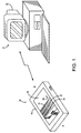
- a flat-bed color scanner 10 is shown with an associated computer system 12.
- the scanner 10 includes a housing 14, and a carriage unit 16 which is contained within the housing.
- the carriage unit 16 is comprised of a light source assembly 18 and a photosensor 20.
- the light source assembly 18 and the photosensor 20 are designed to operate in unison to capture images, graphics and/or text (hereinafter collectively referred to as "images") from a surface of a medium, such as a sheet of paper.
- the light source assembly 18 provides illumination upon the surface of the medium to be scanned, while the photosensor 20 captures reflected light from the illuminated surface of the medium.
- the photosensor 20 may be a charge-coupled device (CCD) or other light sensing device.
- CCD charge-coupled device
- the captured light is then processed to reproduce the images from the surface of the medium.
- the reproduced images may be displayed on a monitor 22 of the computer system 12.
- the maximum scanning area for the scanner 10 is defined by a rectangular opening 24 in the scanner 10.
- the opening 24 is covered by a glass, such that a sheet of paper that is to be scanned may be placed on the glass, above the carriage unit 16. During operation, the surface of the paper adjacent to the glass is scanned by the scanner 10. Except for the light source assembly 18, the scanner 10 is structurally and operationally identical to conventional scanners. The light source assembly 18 will be described in detail below.
- a sheet of paper, or other medium is placed on the glass within the scanning area.
- a scanner cover (not shown) is placed on top of the scanning area, positioning the paper between the glass and a cover.
- a user controls the operation of the scanner 10 by utilizing software that is running on the computer system 12.
- the user is able to manipulate the functions of the scanner 10 by inputting commands into the computer system 12.
- the user initiates the scanning procedure by inputting an appropriate command.
- the carriage unit 16 begins to move in a direction designated by arrow 26.
- the carriage unit 16 is initially positioned near side A.
- the carriage unit 16 advances toward side B in order to scan the entire surface of the paper.
- the light provided by the light source assembly 18 is reflected from the paper and is received by the photosensor 20.
- the photosensor 20 generates electrical signals in response to the varying intensities of the received light.
- the electrical signals are then transmitted to the computer system 12 for processing.
- the computer system 12 is able to reproduce the images on the paper. This reproduced image may be displayed on the monitor 22 of the computer system for editing and/or printing.
- the critical components of the light source assembly 16 are a light emitting diode (LED) 26 and a light transmitting rod lens 28.
- Fig. 2 is a bottom view of the LED 26 and the rod lens 28.
- Fig. 3 is a cross-sectional view of the rod lens 28.
- the LED 26 is a blue light emitting, Gallium Nitride (GaN) based LED.
- the LED 26 may be an LED manufactured by Nichia Chemical Industries, LTD., Tokyo, Japan.
- the LED 26 may be an LED that emits violet or ultraviolet light.
- the operational feasibility for using one of these alternative types of LEDs will depend on the composition of the rod lens 28.
- the LED 26 will be assumed to be an LED that emits blue light when activated.
- the light transmitting rod lens 28 is a solid cylindrical rod that is transparent, allowing light to propagate within the rod lens.
- the rod lens 28 may be composed of glass or plastic material, such as polystyrene, acrylic or polycarbonate.
- the rod lens 28 has a circular cross-section, as shown in Fig. 3.
- the rod lens 28 not only functions as a propagation conduit for light, but also functions as a lens.
- two fluorescent strips 30 and 32 and a non-fluorescent strip 34 are present on the rod lens 28.
- the three strips 30, 32 and 34 operate to receive blue light 36 emitted from the LED 26 and then transmit composite "white" light 38, having components of red light 40, green light 42 and blue light 44.
- the strips 30, 32 and 34 are shown to be separated in Figs. 2 and 3, the strips 30, 32 and 34 may be positioned immediately adjacent to each other, such that no space appears between the strips 30, 32 and 34.
- the fluorescent strips 30 and 32 contain fluorescent material to convert the emitted blue light 36 into the red light 40 and the green light 42.
- the fluorescent strip 30 contains a first fluorescent material that can absorb the emitted blue light 38 and emit the red light 40, while the fluorescent strip 30 contains fluorescent material that can emit green light 42 in response to the emitted blue light 36.
- the non-fluorescent strip 34 does not contain any fluorescent material. The non-fluorescent strip 34 operates to reflect the emitted blue light 36 in order to supply the blue light 44 to form the composite light 38.
- the fluorescent material contained in the fluorescent strips 30 and 32 may be inorganic dyes or organic dyes.
- the inorganic dyes are typically in a solid form, as powders.
- the organic dyes are typically in a liquid form.
- the organic dyes are utilized to fabricate the fluorescent strips 30 and 32.
- the fabrication process of the fluorescent strips 30 and 32 includes combining a selected organic dye with epoxy or other comparable bonding material to form a fluorescent paste.
- the selected organic dye will determine whether the fluorescent paste will be used to form the fluorescent strip 30 or the fluorescent strip 32.
- the fluorescent paste is applied to the exterior surface of the rod lens 28, along the length of the rod lens 28, in order to form one of the fluorescent strips 30 and 32.
- the organic dyes utilized in the fluorescent strips 30 and 32 may be dyes from Lambda Physik, Inc. located in Fort Lauderdale, Florida.
- an organic dye sold under the name of "Pyridine 1” may be utilized to fabricate the fluorescent strip 30, while an organic dye sold under the name of "Coumarin 6" may be utilized to fabricate the fluorescent strip 32.
- the selection of the organic dye will depend on the desired output color light from a particular input color light. In the above examples, Pyridine 1 emits red light when subjected to blue light. However, Coumarin 6 emits green light when subjected to the same blue light.
- other organic fluorescent dyes that are currently available in the market may be utilized in the fluorescent strips 30 and 32.
- the non-fluorescent strip 34 contains diffusive material, such as barium sulfate, magnesia, titania or other comparable material to diffuse and reflect the emitted blue light 36.
- the diffusive material may also be combined with epoxy or other comparable bonding material into a paste and applied to the rod lens 28 in order to fabricate the non-fluorescent strip 34.
- the reflectors 46 and 48 may be composed of silver or aluminum.
- the reflectors 46 function to reflect any light that has propagated through one of the strips 30, 32 and 34, such that the light may be redirected toward a desired direction, i.e., the direction of the composite light 38.
- the reflectors 46 are not illustrated in Fig. 2.
- the reflector 48 reflects light that has reached the end of the rod lens 28 back toward the LED 26, so that some of the reflected light can be integrated into the composite light 35, increasing the intensity of the composite light and the efficiency of the assembly.
- the LED 26 is initially activated to emit the blue source light 36.
- the emitted blue light 36 enters the rod lens 28 through the adjacent end of the rod lens.
- the emitted blue light 36 that impinges upon the non-fluorescent strip 34 is reflected as blue light 44.
- the reflected blue light 44 is focused by the rod lens 28 and is transmitted from the rod lens 28 in a direction generally opposite to the non-fluorescent strip 34, thereby becoming a blue light component of the composite light 38, as shown in Fig. 3.
- the emitted blue light 36 that impinges upon the fluorescent strip 30 is absorbed by the fluorescent material contained within the strip 30.
- the fluorescent material becomes excited and emits the red light 40 through a process known as fluorescence.
- the emitted blue light 36 that impinges upon the fluorescent strip 32 is absorbed by the fluorescent material contained within the fluorescent strip 32.
- the fluorescent material of strip 32 emits the green light 42 in response to the emitted blue light 36.
- the red and green lights 40 and 42 are also focused and transmitted from the rod lens 28 to become red and green components of the composite light 38.
- the composite light 38 emanates from the entire length of the rod lens 28, since the color lights 40, 42 and 44 are being emitted along the strips 30, 32 and 34. Therefore, the composite light 38 provides the desired linear illumination on a scanning surface.
- the amount of red, green and blue light components of the composite light 38 is proportionally related to the surface area of the strips 30, 32 and 34. Therefore, the amount of a particular color component of the composite light 38 can be increased by widening the width of a corresponding strip. For example, if a greater amount of red light is desired, the fluorescent strip 30 can be widened to supply additional red light to the composite light 38. Conversely, decreasing the width of a strip has the opposite effect. By manipulating the red, green and blue light components, the composite light 38 can be manipulated to better match the tristimulus values for the human eye, increasing the color quality of reproduced images.
- a light transmitting rod lens 50 in accordance with a second embodiment of the invention is shown.
- Fig. 4 is a bottom view of the rod lens 50.
- Fig. 5 is a cross-sectional view of the rod lens 50.
- the rod lens 50 is virtually identical to the rod lens 28 of Figs. 2 and 3.
- the only substantive difference between the rod lens 50 and the rod lens 28 is that the rod lens 50 includes a single fluorescent strip 52, which essentially replaces the strips 30 and 32 of the rod lens 28.
- the fluorescent strip 52 is comprised of organic dyes that were utilized in the strips 30 and 32.
- the fluorescent strip 52 may contain a mixture of Pyridine 1 and Coumarin 6.
- the fluorescent strip 52 operates to generate the red and green lights 40 and 42 from the emitted blue light 36.
- the blue light component of the composite light 38 is provided by the non-fluorescent strip 34.
- the fluorescent strip 52 may be fabricated and affixed to the rod lens 50 in the same manner as the strips 30 and 32 of the rod lens 28.
- a mixture of organic dyes may be bonded together by epoxy or other comparable bonding material to form a paste.
- the proportions of organic dyes may vary in the mixture depending on the amount of a particular color desired in the composite light 38. For example, if more red light component is desired, the mixture may include more Pyridine than Coumarin 6.
- the paste is then applied to the exterior surface of the rod lens 50 to form the fluorescent strip 52.
- the LED 26 is activated to emit the blue source light 36.
- the emitted blue light 36 propagates through the adjacent end of the rod lens 50.
- portions of the emitted blue light 36 impinge upon the fluorescent strip 52 and the non-fluorescent strip 34.
- Some of the emitted light that impinges upon the non-fluorescent strip 34 is reflected as the blue light 44.
- some of the emitted blue light 36 that impinges upon the fluorescent strip 52 is absorbed by the fluorescent material of the strip 52. Since the strip contains two types of fluorescent material, the fluorescent-strip 52 emits both the red light 40 and the green light 42.
- the red, green and blue lights 40, 42 and 44 are focused by the rod lens 50 and then transmitted from the rod lens 50 to become components of the composite light 38. Light that reaches the other end of the rod lens 50 or travels through one of the strips 34 and 52 is reflected by the reflectors 48 and 46, respectively.
- a first alternative configuration includes a second LED located near the opposite end of the rod lens 28 or 50 from the LED 26 and the removal of the reflector 48 from the rod lens 28 or 50.
- the LED 26 and the second LED will both emit blue light into the rod lens 28 or 50, increasing the intensity of the resulting composite light.
- a second alternative configuration relates to the fluorescent strips utilized in the various rod lenses.
- the liquid organic dyes are diffused into the interior region near the surface of the rod lens.
- the rod lens is preferably composed of a plastic material.
- the region of the rod lens diffused by the organic dyes can be a long strip-like area near the exterior surface of the rod lens. This region containing the organic dyes can function as one of the fluorescent strips 30, 32 and 52.
- a third alternative configuration involves utilizing a rod lens having a U-shaped cross-section or an elliptical cross-section. These different cross-sections facilitate the focusing function of the rod lens. However, the overall operation does not differ in either of these alternative embodiments.
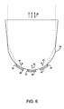
- the two alternative cross-sections for a rod lens are illustrated in Figs. 6 and 7.
- a cross-sectional view of a U-shaped rod lens 54 in accordance with a first alternative embodiment of the invention is shown.
- a cross-sectional view of an elliptical rod lens 56 in accordance with a second alternative embodiment of the invention is shown in Fig. 7.
- Both rod lenses 54 and 56 are shown to include the strips 30, 32 and 34 that are attached to the reflectors 46. However, the strips 30 and 32 may be replaced with the fluorescent strip 52 of Figs. 4 and 5.
- the cross-sectional shapes of the rod lenses 54 and 56 focus the different color lights 40, 42 and 44 to form the composite light 38, which then illuminates a desired linear portion of a scanned surface.
- a method of providing linear illumination in scanning devices will be described with reference to Fig. 8.
- light of a first wavelength is emitted by a LED.
- the LED is a Gallium Nitride (GaN) based LED that is designed to emit blue light.
- the emitted light of the first wavelength is then received by a light transmitting rod lens at step 62.
- the emitted light enters the rod lens through one end of the rod lens.
- the emitted light is absorbed by a fluorescent strip on the rod lens.
- step 66 light of a second wavelength is emitted by the fluorescent strip through fluorescence.
- the light of the second wavelength is then focused within the rod lens at step 68.
- the cross-sectional shape of the rod lens allows the light of the second wavelength to be focused.
- the light of the second wavelength is transmitted from the rod lens to a target surface.
Abstract
Description
- The invention relates generally to scanning devices and more particularly to a light source assembly for a scanning device.
- Scanning devices such as flat-bed color scanners and color copying machines operate by capturing light reflected from a scanned medium and using the captured light to reproduce images, graphics and/or text from the medium. In a typical scanning device, a light source assembly projects a thin, linear light pattern, that is reflected and then captured by a photo-sensing component. A common photo-sensing component of a scanning device is a charge-coupled device (CCD) having an array of photosensors positioned in a thin strip. The light source assembly is positioned adjacent to the CCD in order to effectuate the projection and capture of the linear light pattern. Depending upon the characteristics of the light being received by the CCD, the definition and color composition of the images, graphics and/or text on the medium can be determined. An entire surface of the medium can be scanned by moving the light source assembly and the CCD relative to the medium. Alternatively, the medium may be moved relative to the light source assembly and the CCD to provide scanning of the surface of the medium.
- There are various types of conventional light source assemblies for scanning devices. A conventional light source assembly may include a fluorescent tube having a longitudinally extending aperture formed by removing one or more interior coatings along a lengthwise region of the bulb. A linear illumination is provided by the generated light that escapes from the fluorescent tube through the aperture. However, a more common type of light source assembly for scanning devices utilizes a transparent solid rod to receive light from an electric lamp and to transmit the received light in a direction perpendicular to the length of the rod and along the entire length of the rod to provide the linear illumination. These rod-type light source assemblies tend to be less bulky and require less power than the tube type light source assemblies.
- U.S. Patent No. 4,924,357 to Yamashita et al. discloses a light source assembly that utilizes the above-described rod for business machines, such as scanners and copying machines. The light source assembly of Yamashita et al. includes a lamp that is positioned at one end of a solid transparent rod to emit source light through the interior region of the rod in a lengthwise direction. Various lamps are disclosed that may be utilized in the light source assembly of Yamashita et al. A tungsten halogen lamp, a mercury lamp, a xenon lamp and a flash lamp are specifically identified as possible candidates for generating the light energy for the light source assembly. The rod is described as a solid light-transmitting rod having a circular or elliptical cross-section. Along the length of the rod, a strip of diffusion material is coated onto the outer surface of the rod. The entire rod is enclosed in an aluminum cylinder encasing, which has a slit along its length. The rod is positioned in the encasing such that the diffusion strip on the rod is located opposite to the slit. The diffusion strip operates to diffuse light from the lamp that is propagating through the interior region of the rod. In effect, the diffusion strip redirects the source light from the lamp, that is being reflected from the surface of the rod and the interior surface of the encasing, towards the slit in the encasing such that the redirected light can emanate from the entire length of the slit. The emission of light from the slit in the encasing provides a linear illumination.
- A still more power-efficient light source assembly is described in U.S. Patent No. 5,753,906 to Gennetten. The light source assembly of Gennetten utilizes light emitting diodes (LEDs) to provide the linear illumination. LEDs have a number of advantages over electrical lamps. For example, LEDs are less expensive and more compact than electrical lamps. In addition, LEDs operate at a significantly lower voltage that electrical lamps, while providing a stable geometrical light output, i.e., uniform illumination. The Gennetten light source assembly includes four different types of LEDs, wherein each type of LED is designed to emit light of a particular color. In one embodiment, the LEDs are positioned along a straight line in an alternating fashion. The LEDs are placed in groups of four LEDs, such that the same color LED will be present every fourth LED. In another embodiment, the LEDs form a 4 x N array such that a row of N LEDs in the array is of one color. In either embodiment, the linearly distributed LEDs provide the linear illumination required for scanning devices.
- Although the Gennetten light source assembly utilizes LEDs which have advantages over conventional lamps, the great number of LEDs that are required by the Gennetten light source assembly counterbalances some of the advantages. The Gennetten light source assembly may require tens of LEDs, whereas the Yamashita et al. light source assembly only requires a single lamp.
- The present invention seeks to provide an improved light source assembly for scanning devices.
- According to an aspect of the present invention there is provided a light source assembly as specified in claim 1.
- According to another aspect of the present invention a method of providing illumination as specified in claim 7.
- The preferred embodiment can provide a compact light source assembly for scanning devices that exploits some of the advantages of rod-type light source assemblies, while also taking advantage of the favorable properties of LEDs.
- In the preferred embodiment, a light source assembly and method of providing illumination on a desired surface utilize a fluorescent material to generate composite "white" light from a source light of a particular color, i.e., a particular wavelength. The embodiment takes advantage of fluorescence to provide the various color lights needed to form the desired composite light from the single color source light. The light source assembly is optimally designed for use in scanning devices, such as flat-bed color scanners, in which linear illumination is necessary to capture images, graphics and/or text from a target scanned surface.
- The light source assembly includes a source light generator and a light transmitting rod. The source light generator is preferably a light emitting diode (LED). Although an LED that can emit violet or ultraviolet light may be utilized, a Gallium Nitride (GaN) based LED that emits blue light of high intensity is preferred, e.g., the LEDs manufactured by Nichia Chemical Industries, LTD., Tokyo, Japan. In an alternative configuration, the light source assembly employs two LEDs to supply the source light. The two LEDs are positioned adjacent to opposite ends of the light transmitting rod to emit the source light into the rod from both ends.
- The light transmitting rod is preferably a solid transparent structure designed to receive the source light from at least one end of the rod. The composition of the light transmitting rod allows the rod to be a propagation medium for the source light. The light transmitting rod may be composed of glass or plastic material, such as polystyrene, acrylic, or polycarbonate. The light transmitting rod includes at least one fluorescent strip, located near the exterior surface of the rod.
- The fluorescent strip extends along the length of the rod. the fluorescent strip contains a fluorescent material having a property to absorb the source light and then to emit light of a different color. The fluorescent material may be an inorganic fluorescent dye or an organic fluorescent dye. In the preferred embodiment, organic dye is utilized to form the fluorescent strip by combining the organic dye, which is in a liquid state, with epoxy or other comparable material. The dye-epoxy compound is applied to the light transmitting rod to fabricate the fluorescent strip. In an alternative configuration, the organic dye is diffused into the light transmitting rod to form a region of fluorescent material along the length of the light transmitting rod.
- In a first embodiment of the invention, the light transmitting rod includes one non-fluorescent and two fluorescent strips that are positioned parallel to one another along the length of the rod. A first fluorescent strip contains an organic dye that can absorb a blue source light and emit red light. A second fluorescent strip contains a different organic dye that can absorb the blue source light and emit green light. However, the non-fluorescent strip does not contain any organic dye. The non-fluorescent strip contains a diffusive material, such as barium sulfate, magnesia or titania, to reflect the blue source light. The emitted red and green lights, along with the reflected blue light, are focused within the light transmitting rod to a target scanned surface. The different color lights then emanate from the rod as a composite "white" light to provide illumination. The emanation occurs along the entire length of the light transmitting rod, creating the desired linear illumination.
- In a second embodiment of the invention, the light transmitting rod includes a compound fluorescent strip that contains both organic dyes utilized in the first embodiment to absorb the blue source light and emit both red and green lights. Essentially, the two fluorescent strips of the first embodiment are integrated into a single strip to generate the red and green lights. The second embodiment also includes a non-fluorescent strip to reflect the blue source light to supply blue light to the composite light. The three color lights from the compound fluorescent strip and the non-fluorescent strip form the composite light and are transmitted from the light transmitting rod to a target scanned surface.
- In either embodiment, the light transmitting rod is designed to function as a lens to focus the lights transmitted from the strips to the desired scanning surface. The light transmitting rod can have various shapes to accomplish the focusing function. The light transmitting rod may have a circular, a U-shaped, or an elliptical cross-section. However, the cross-sectional shape of the light transmitting rod is not critical to the invention.
- An advantage of the embodiments is that an LED is employed to provide the source light. The use of the LED incorporates all the advantages of a solid state device over conventional electrical lamps, such as lower cost, stable geometrical light output, lower operating voltage and compactness.
- Another advantage is that the blue source light and the red and green lights that are emitted from the organic dyes closely match the tristimulus values for the human eye, increasing the color quality of scanned images.
- Still another advantage is that, unlike conventional light source assemblies utilizing LEDs, the invention requires a single LED, instead of tens of LEDs. The result is a compact light source assembly that is less expensive to manufacture. In addition, since only the single LED requires power, less energy is needed to operate the light source assembly.
- An embodiment of the present invention is described below, by way of example only, with reference to the accompanying drawings, in which:
- Fig. 1 is a perspective view of a scanning device and an associated computer system.
- Fig. 2 is a bottom view of a light source assembly including a light emitting diode (LED) and a light transmitting rod lens in accordance with a first embodiment of the present invention.
- Fig. 3 is a cross-sectional view of the light transmitting rod lens of Fig. 2.
- Fig. 4 is a bottom view of a light source assembly including an LED and a light transmitting rod lens in accordance with a second embodiment of the present invention.
- Fig. 5 is a cross-sectional view of the light transmitting rod lens of Fig. 4.
- Fig. 6 is a cross-sectional view of a light transmitting rod lens having a U-shaped cross-section in accordance with a first alternative embodiment of the present invention.
- Fig. 7 is a cross-sectional view of a light transmitting rod lens having an elliptical cross-section in accordance with a second alternative embodiment of the present invention.
- Fig. 8 is a flow chart of an embodiment of a method of providing inear illumination in scanning devices.
-
- With reference to Fig. 1, a flat-
bed color scanner 10 is shown with an associatedcomputer system 12. Thescanner 10 includes ahousing 14, and acarriage unit 16 which is contained within the housing. Thecarriage unit 16 is comprised of alight source assembly 18 and aphotosensor 20. Thelight source assembly 18 and the photosensor 20 are designed to operate in unison to capture images, graphics and/or text (hereinafter collectively referred to as "images") from a surface of a medium, such as a sheet of paper. Thelight source assembly 18 provides illumination upon the surface of the medium to be scanned, while thephotosensor 20 captures reflected light from the illuminated surface of the medium. The photosensor 20 may be a charge-coupled device (CCD) or other light sensing device. The captured light is then processed to reproduce the images from the surface of the medium. The reproduced images may be displayed on amonitor 22 of thecomputer system 12. - The maximum scanning area for the
scanner 10 is defined by arectangular opening 24 in thescanner 10. Theopening 24 is covered by a glass, such that a sheet of paper that is to be scanned may be placed on the glass, above thecarriage unit 16. During operation, the surface of the paper adjacent to the glass is scanned by thescanner 10. Except for thelight source assembly 18, thescanner 10 is structurally and operationally identical to conventional scanners. Thelight source assembly 18 will be described in detail below. - In operation, a sheet of paper, or other medium, is placed on the glass within the scanning area. A scanner cover (not shown) is placed on top of the scanning area, positioning the paper between the glass and a cover. Preferably, a user controls the operation of the
scanner 10 by utilizing software that is running on thecomputer system 12. The user is able to manipulate the functions of thescanner 10 by inputting commands into thecomputer system 12. The user initiates the scanning procedure by inputting an appropriate command. In response to the command, thecarriage unit 16 begins to move in a direction designated byarrow 26. Thecarriage unit 16 is initially positioned near side A. During a scanning mode, thecarriage unit 16 advances toward side B in order to scan the entire surface of the paper. As thecarriage unit 16 passes under the paper, the light provided by thelight source assembly 18 is reflected from the paper and is received by thephotosensor 20. - The
photosensor 20 generates electrical signals in response to the varying intensities of the received light. The electrical signals are then transmitted to thecomputer system 12 for processing. By calculating the intensities of the reflected light that is captured by thephotosensor 20, thecomputer system 12 is able to reproduce the images on the paper. This reproduced image may be displayed on themonitor 22 of the computer system for editing and/or printing. - Turning to Figs. 2 and 3, critical components of the
light source assembly 18 of Fig. 1 in accordance with a first embodiment of the invention are shown. The critical components of thelight source assembly 16 are a light emitting diode (LED) 26 and a light transmittingrod lens 28. Fig. 2 is a bottom view of theLED 26 and therod lens 28. Fig. 3 is a cross-sectional view of therod lens 28. Preferably, theLED 26 is a blue light emitting, Gallium Nitride (GaN) based LED. For example, theLED 26 may be an LED manufactured by Nichia Chemical Industries, LTD., Tokyo, Japan. Alternatively, theLED 26 may be an LED that emits violet or ultraviolet light. However, the operational feasibility for using one of these alternative types of LEDs will depend on the composition of therod lens 28. For discussion below, theLED 26 will be assumed to be an LED that emits blue light when activated. - The light
transmitting rod lens 28 is a solid cylindrical rod that is transparent, allowing light to propagate within the rod lens. Therod lens 28 may be composed of glass or plastic material, such as polystyrene, acrylic or polycarbonate. Therod lens 28 has a circular cross-section, as shown in Fig. 3. As will be described below, therod lens 28 not only functions as a propagation conduit for light, but also functions as a lens. In this embodiment, twofluorescent strips non-fluorescent strip 34 are present on therod lens 28. The threestrips LED 26 and then transmit composite "white" light 38, having components ofred light 40,green light 42 andblue light 44. Although thestrips strips strips - In order to generate the composite light 38 from the emitted
blue light 36, the fluorescent strips 30 and 32 contain fluorescent material to convert the emitted blue light 36 into thered light 40 and thegreen light 42. Thefluorescent strip 30 contains a first fluorescent material that can absorb the emittedblue light 38 and emit thered light 40, while thefluorescent strip 30 contains fluorescent material that can emitgreen light 42 in response to the emittedblue light 36. However, thenon-fluorescent strip 34 does not contain any fluorescent material. Thenon-fluorescent strip 34 operates to reflect the emitted blue light 36 in order to supply theblue light 44 to form thecomposite light 38. - The fluorescent material contained in the fluorescent strips 30 and 32 may be inorganic dyes or organic dyes. The inorganic dyes are typically in a solid form, as powders. However, the organic dyes are typically in a liquid form. Preferably, the organic dyes are utilized to fabricate the fluorescent strips 30 and 32. The fabrication process of the fluorescent strips 30 and 32 includes combining a selected organic dye with epoxy or other comparable bonding material to form a fluorescent paste. The selected organic dye will determine whether the fluorescent paste will be used to form the
fluorescent strip 30 or thefluorescent strip 32. The fluorescent paste is applied to the exterior surface of therod lens 28, along the length of therod lens 28, in order to form one of the fluorescent strips 30 and 32. - As an example, the organic dyes utilized in the fluorescent strips 30 and 32 may be dyes from Lambda Physik, Inc. located in Fort Lauderdale, Florida. For example, an organic dye sold under the name of "Pyridine 1" may be utilized to fabricate the
fluorescent strip 30, while an organic dye sold under the name of "Coumarin 6" may be utilized to fabricate thefluorescent strip 32. The selection of the organic dye will depend on the desired output color light from a particular input color light. In the above examples, Pyridine 1 emits red light when subjected to blue light. However, Coumarin 6 emits green light when subjected to the same blue light. Besides the dyes from Lambda Physik, Inc., other organic fluorescent dyes that are currently available in the market may be utilized in the fluorescent strips 30 and 32. - The
non-fluorescent strip 34 contains diffusive material, such as barium sulfate, magnesia, titania or other comparable material to diffuse and reflect the emittedblue light 36. The diffusive material may also be combined with epoxy or other comparable bonding material into a paste and applied to therod lens 28 in order to fabricate thenon-fluorescent strip 34. - Affixed over the
strips reflectors 46. In addition, areflector 48 is located over one end of therod lens 28. Thereflectors reflectors 46 function to reflect any light that has propagated through one of thestrips composite light 38. For simplification, thereflectors 46 are not illustrated in Fig. 2. Thereflector 48 reflects light that has reached the end of therod lens 28 back toward theLED 26, so that some of the reflected light can be integrated into the composite light 35, increasing the intensity of the composite light and the efficiency of the assembly. - In operation, the
LED 26 is initially activated to emit the blue source light 36. The emittedblue light 36 enters therod lens 28 through the adjacent end of the rod lens. As theblue light 36 propagates along the length of therod lens 28, some of theblue light 36 impinges upon thestrips non-fluorescent strip 34 is reflected asblue light 44. The reflectedblue light 44 is focused by therod lens 28 and is transmitted from therod lens 28 in a direction generally opposite to thenon-fluorescent strip 34, thereby becoming a blue light component of thecomposite light 38, as shown in Fig. 3. The emitted blue light 36 that impinges upon thefluorescent strip 30 is absorbed by the fluorescent material contained within thestrip 30. The fluorescent material becomes excited and emits thered light 40 through a process known as fluorescence. Similarly, the emitted blue light 36 that impinges upon thefluorescent strip 32 is absorbed by the fluorescent material contained within thefluorescent strip 32. However, the fluorescent material ofstrip 32 emits thegreen light 42 in response to the emittedblue light 36. The red andgreen lights rod lens 28 to become red and green components of thecomposite light 38. Thecomposite light 38 emanates from the entire length of therod lens 28, since the color lights 40, 42 and 44 are being emitted along thestrips composite light 38 provides the desired linear illumination on a scanning surface. - The amount of red, green and blue light components of the
composite light 38 is proportionally related to the surface area of thestrips composite light 38 can be increased by widening the width of a corresponding strip. For example, if a greater amount of red light is desired, thefluorescent strip 30 can be widened to supply additional red light to thecomposite light 38. Conversely, decreasing the width of a strip has the opposite effect. By manipulating the red, green and blue light components, thecomposite light 38 can be manipulated to better match the tristimulus values for the human eye, increasing the color quality of reproduced images. - Referring now to Figs. 4 and 5, a light transmitting
rod lens 50 in accordance with a second embodiment of the invention is shown. Fig. 4 is a bottom view of therod lens 50. Fig. 5 is a cross-sectional view of therod lens 50. When applicable, the same reference numerals of Figs. 2 and 3 will be used. Therod lens 50 is virtually identical to therod lens 28 of Figs. 2 and 3. The only substantive difference between therod lens 50 and therod lens 28 is that therod lens 50 includes a singlefluorescent strip 52, which essentially replaces thestrips rod lens 28. Thefluorescent strip 52 is comprised of organic dyes that were utilized in thestrips fluorescent strip 52 may contain a mixture of Pyridine 1 and Coumarin 6. Thefluorescent strip 52 operates to generate the red andgreen lights blue light 36. The blue light component of thecomposite light 38 is provided by thenon-fluorescent strip 34. - The
fluorescent strip 52 may be fabricated and affixed to therod lens 50 in the same manner as thestrips rod lens 28. A mixture of organic dyes may be bonded together by epoxy or other comparable bonding material to form a paste. The proportions of organic dyes may vary in the mixture depending on the amount of a particular color desired in thecomposite light 38. For example, if more red light component is desired, the mixture may include more Pyridine than Coumarin 6. The paste is then applied to the exterior surface of therod lens 50 to form thefluorescent strip 52. - In operation, the
LED 26 is activated to emit the blue source light 36. The emittedblue light 36 propagates through the adjacent end of therod lens 50. Within therod lens 50, portions of the emitted blue light 36 impinge upon thefluorescent strip 52 and thenon-fluorescent strip 34. Some of the emitted light that impinges upon thenon-fluorescent strip 34 is reflected as theblue light 44. However, some of the emitted blue light 36 that impinges upon thefluorescent strip 52 is absorbed by the fluorescent material of thestrip 52. Since the strip contains two types of fluorescent material, the fluorescent-strip 52 emits both thered light 40 and thegreen light 42. The red, green andblue lights rod lens 50 and then transmitted from therod lens 50 to become components of thecomposite light 38. Light that reaches the other end of therod lens 50 or travels through one of thestrips reflectors - Alternative configurations for the
light source assembly 18 havingrod lens 28 or therod lens 50 are contemplated. A first alternative configuration includes a second LED located near the opposite end of therod lens LED 26 and the removal of thereflector 48 from therod lens LED 26 and the second LED will both emit blue light into therod lens - A second alternative configuration relates to the fluorescent strips utilized in the various rod lenses. Instead of applying the fluorescent material as a coating onto the exterior surfaces of the rod lens, the liquid organic dyes are diffused into the interior region near the surface of the rod lens. In order to implement this configuration, the rod lens is preferably composed of a plastic material. The region of the rod lens diffused by the organic dyes can be a long strip-like area near the exterior surface of the rod lens. This region containing the organic dyes can function as one of the fluorescent strips 30, 32 and 52.
- A third alternative configuration involves utilizing a rod lens having a U-shaped cross-section or an elliptical cross-section. These different cross-sections facilitate the focusing function of the rod lens. However, the overall operation does not differ in either of these alternative embodiments. The two alternative cross-sections for a rod lens are illustrated in Figs. 6 and 7.
- In Fig. 6, a cross-sectional view of a
U-shaped rod lens 54 in accordance with a first alternative embodiment of the invention is shown. A cross-sectional view of anelliptical rod lens 56 in accordance with a second alternative embodiment of the invention is shown in Fig. 7. Bothrod lenses strips reflectors 46. However, thestrips fluorescent strip 52 of Figs. 4 and 5. The cross-sectional shapes of therod lenses different color lights composite light 38, which then illuminates a desired linear portion of a scanned surface. - A method of providing linear illumination in scanning devices will be described with reference to Fig. 8. At
step 60, light of a first wavelength is emitted by a LED. Preferably, the LED is a Gallium Nitride (GaN) based LED that is designed to emit blue light. The emitted light of the first wavelength is then received by a light transmitting rod lens atstep 62. Preferably, the emitted light enters the rod lens through one end of the rod lens. Atstep 64, the emitted light is absorbed by a fluorescent strip on the rod lens. Next, atstep 66, light of a second wavelength is emitted by the fluorescent strip through fluorescence. The light of the second wavelength is then focused within the rod lens atstep 68. The cross-sectional shape of the rod lens allows the light of the second wavelength to be focused. Atstep 70, the light of the second wavelength is transmitted from the rod lens to a target surface. - The discloses in United States patent application no. 09/139,904, from which this application claims priority, and in the abstract accompanying this application are incorporated herein by reference.
Claims (10)
- A light source assembly (18) for scanning devices (10) comprising:a light source (26) for emitting light of a first center wavelength (36);an elongated structure (28; 50; 54; 56) including a first port on an exterior surface, said first port being optically coupled to said light source to receive said light of said first center wavelength from said light source, said exterior surface defining an interior region of said elongated structure to provide a propagation conduit for said light of said first center wavelength, said elongated structure including a second port along a length of said elongated structure to direct a composite light (38) to a target scanned surface in response to said light of said first center wavelength; anda fluorescent material (30 and 32; 52) operationally associated with said elongated structure, said fluorescent material being distributed generally along a length-wise direction of said elongated structure, said fluorescent material having a property to absorb said light of said first center wavelength and emit light of a second center wavelength (40 and 42), said light of said second center wavelength being at least a component of said composite light.
- The light source assembly of claim 1 wherein said light source (26) is a light emitting diode positioned adjacent to said first port of said elongated structure (28; 50; 54; 56) to emit said light of said first center wavelength (36) to said interior region via said first port.
- The light source assembly of claim 1 or 2 wherein said light source (26) is a Gallium Nitride (GaN) based light emitting diode (LED), said GaN based LED configured to emit said light of said first center wavelength (36) wherein said first center wavelength is within a blue region of a visible light spectrum.
- The light source assembly of claim 1, 2 or 3 wherein said fluorescent material (30 and 32; 52) is a fluorescent organic dye.
- The light source assembly of claim 1, 2, 3 or 4 wherein said elongated structure (28; 50; 54; 56) is a solid rod composed of a transparent material, said transparent material providing a propagation medium for said light of said first center wavelength (36) within said elongated structure.
- The light source assembly of claim 1, 2, 3, 4 or 5 wherein said fluorescent material (30 and 32; 52) is diffused into said elongated structure (28; 50; 54; 56), thereby forming a fluorescent region within said elongated structure.
- A method of providing illumination on a scanned surface comprising steps of:emitting (60) light of a first center wavelength (36) from a light source (26);receiving (62) said light of said first center wavelength through a port at one end of an elongated rod (28; 50; 54; 56), said elongated rod being transparent to allow said light of said first center wavelength to propagate within said elongated rod;absorbing (64) said light of said first center wavelength by a fluorescent material (30 and 32; 52) located near an outer surface of said elongated rod, said fluorescent material being distributed generally along a lengthwise direction of said elongated rod;emitting (66) light of a second center wavelength (40 and 42) by said fluorescent material in response to an absorption of said light of said first center wavelength; andtransmitting (70) said light of said second center wavelength from said fluorescent material in a direction away from said elongated rod and toward a target surface.
- The method of claim 7 wherein said step of emitting (60) said light of said first center wavelength (36) includes employing a light emitting diode (26) to generate said light of said first center wavelength.
- The method of claim 7 or 8 wherein said step of emitting (60) said light of said first center wavelength includes employing a Gallium Nitride (GaN) based light emitting diode (26) to generate said light within a blue region of a visible light spectrum.
- The method of claim 7, 8 or 9 comprising steps of:absorbing said light of said first center wavelength (36) by a second fluorescent material (30 and 32; 52) located near said outer surface of said elongated rod (28; 50; 54; 56), said second fluorescent material being distributed generally along said lengthwise direction of said elongated rod; andemitting light of a third center wavelength (40 and 42) by said second fluorescent material in response to an absorption of said light of said first center wavelength (36) by said second fluorescent material.
Applications Claiming Priority (2)
| Application Number | Priority Date | Filing Date | Title |
|---|---|---|---|
| US09/139,904 US6139174A (en) | 1998-08-25 | 1998-08-25 | Light source assembly for scanning devices utilizing light emitting diodes |
| US139904 | 1998-08-25 |
Publications (2)
| Publication Number | Publication Date |
|---|---|
| EP0982924A2 true EP0982924A2 (en) | 2000-03-01 |
| EP0982924A3 EP0982924A3 (en) | 2001-01-10 |
Family
ID=22488821
Family Applications (1)
| Application Number | Title | Priority Date | Filing Date |
|---|---|---|---|
| EP99305871A Ceased EP0982924A3 (en) | 1998-08-25 | 1999-07-23 | Light source assembly for scanning devices |
Country Status (3)
| Country | Link |
|---|---|
| US (1) | US6139174A (en) |
| EP (1) | EP0982924A3 (en) |
| JP (1) | JP4785218B2 (en) |
Cited By (8)
| Publication number | Priority date | Publication date | Assignee | Title |
|---|---|---|---|---|
| WO2002070948A1 (en) * | 2001-03-01 | 2002-09-12 | Wavelight Laser Technologie Ag | Device for producing a white light |
| US7037259B2 (en) * | 2001-07-06 | 2006-05-02 | Fuji Photo Film Co., Ltd. | Light source device and image capturing device |
| EP1706665A2 (en) * | 2003-12-31 | 2006-10-04 | Ilight Technologies, Inc. | Illumination device for simulating neon or similar lighting using phosphorescent dye |
| US7264367B2 (en) | 2001-10-18 | 2007-09-04 | Ilight Technologies, Inc. | Illumination device for simulating neon or similar lighting in various colors |
| US7264366B2 (en) | 2001-10-18 | 2007-09-04 | Ilight Technologies, Inc. | Illumination device for simulating neon or similar lighting using phosphorescent dye |
| FR2948173A1 (en) * | 2009-08-13 | 2011-01-21 | Franck Andre Marie Guigan | Light section device for e.g. flat backlighting panels of TVs, has condenser modifying divergent light beam from deviator to decrease its solid emission angle, where external wall of condenser is confounded with side face |
| CN104170363A (en) * | 2012-03-14 | 2014-11-26 | 三菱电机株式会社 | Light source device |
| CN105008795A (en) * | 2012-12-28 | 2015-10-28 | 英特曼帝克司公司 | Solid-state lamps utilizing photoluminescence wavelength conversion components |
Families Citing this family (80)
| Publication number | Priority date | Publication date | Assignee | Title |
|---|---|---|---|---|
| US6299338B1 (en) * | 1998-11-30 | 2001-10-09 | General Electric Company | Decorative lighting apparatus with light source and luminescent material |
| US6488397B1 (en) * | 1999-01-28 | 2002-12-03 | Bridgestone Corporation | Linear luminous body and production method thereof and scanner |
| US6299329B1 (en) * | 1999-02-23 | 2001-10-09 | Hewlett-Packard Company | Illumination source for a scanner having a plurality of solid state lamps and a related method |
| US6357904B1 (en) * | 1999-04-19 | 2002-03-19 | Nec Corporation | Linear illumination device |
| TW460716B (en) * | 1999-12-17 | 2001-10-21 | Toshiba Corp | Light guide, line illumination apparatus, and image acquisition system |
| US7049761B2 (en) | 2000-02-11 | 2006-05-23 | Altair Engineering, Inc. | Light tube and power supply circuit |
| US6883926B2 (en) * | 2000-07-25 | 2005-04-26 | General Electric Company | Light emitting semi-conductor device apparatus for display illumination |
| US6783269B2 (en) * | 2000-12-27 | 2004-08-31 | Koninklijke Philips Electronics N.V. | Side-emitting rod for use with an LED-based light engine |
| US6634779B2 (en) * | 2001-01-09 | 2003-10-21 | Rpm Optoelectronics, Inc. | Method and apparatus for linear led lighting |
| US7048423B2 (en) * | 2001-09-28 | 2006-05-23 | Visteon Global Technologies, Inc. | Integrated light and accessory assembly |
| US7374319B2 (en) * | 2001-10-31 | 2008-05-20 | Itc, Incorporated | Lighted handle |
| US6592240B2 (en) * | 2001-10-31 | 2003-07-15 | Itc Incorporated | Lighted handle |
| US6851820B2 (en) * | 2002-06-26 | 2005-02-08 | Weber-Stephen Products Company | Barbecue grill light |
| DE10231257A1 (en) * | 2002-07-11 | 2004-01-22 | Philips Intellectual Property & Standards Gmbh | tanning device |
| US6860628B2 (en) * | 2002-07-17 | 2005-03-01 | Jonas J. Robertson | LED replacement for fluorescent lighting |
| US6821010B2 (en) * | 2002-11-15 | 2004-11-23 | The Holmes Group, Inc. | Decorative lamp with illuminated color changeable column |
| US6997584B1 (en) * | 2002-12-12 | 2006-02-14 | Russell Rothan | Bicycle lamp |
| US7362320B2 (en) * | 2003-06-05 | 2008-04-22 | Hewlett-Packard Development Company, L.P. | Electronic device having a light emitting/detecting display screen |
| US20050068790A1 (en) * | 2003-09-25 | 2005-03-31 | Love David A. | Light emitting diode glow tube |
| US7746520B2 (en) * | 2004-11-23 | 2010-06-29 | Xerox Corporation | Document illuminator |
| US7593143B2 (en) * | 2005-03-31 | 2009-09-22 | Xerox Corporation | Compound curved concentrator based illuminator |
| US7715063B2 (en) * | 2005-03-31 | 2010-05-11 | Xerox Corporation | CVT integrated illuminator |
| JP4732783B2 (en) * | 2005-04-19 | 2011-07-27 | 富士フイルム株式会社 | Endoscope lighting system |
| WO2006133214A2 (en) * | 2005-06-07 | 2006-12-14 | Optical Research Associates | Phosphor wheel illuminator |
| US7385489B2 (en) * | 2005-07-22 | 2008-06-10 | Visteon Global Technologies, Inc. | Instrument panel assembly |
| US7249865B2 (en) * | 2005-09-07 | 2007-07-31 | Plastic Inventions And Patents | Combination fluorescent and LED lighting system |
| US20070064409A1 (en) * | 2005-09-21 | 2007-03-22 | Ilight Technologies, Inc. | Elongated illumination device having uniform light intensity distribution |
| DE102006008840B4 (en) * | 2006-02-25 | 2009-05-14 | Fraunhofer-Gesellschaft zur Förderung der angewandten Forschung e.V. | Cylindrical object lighting device, surface inspection method and computer program product performed thereby |
| US20080151535A1 (en) * | 2006-12-26 | 2008-06-26 | De Castris Pierre | LED lighting device for refrigerated food merchandising display cases |
| US7901106B2 (en) * | 2006-12-29 | 2011-03-08 | Texas Instruments Incorporated | Solid-state illuminator for display applications |
| US8333494B2 (en) * | 2007-07-05 | 2012-12-18 | I2Ic Corporation | Multicolored linear light source |
| US8118447B2 (en) | 2007-12-20 | 2012-02-21 | Altair Engineering, Inc. | LED lighting apparatus with swivel connection |
| US7712918B2 (en) * | 2007-12-21 | 2010-05-11 | Altair Engineering , Inc. | Light distribution using a light emitting diode assembly |
| JP4930363B2 (en) * | 2007-12-26 | 2012-05-16 | 富士ゼロックス株式会社 | Image reading device |
| US20090261706A1 (en) * | 2008-01-28 | 2009-10-22 | Eliot Sorella | LED Replacement Light Tube for Fluorescent Light Fixture |
| US8360599B2 (en) | 2008-05-23 | 2013-01-29 | Ilumisys, Inc. | Electric shock resistant L.E.D. based light |
| ATE474960T1 (en) * | 2008-06-04 | 2010-08-15 | Leif Levon | VOLATILE SAFETY REFLECTORS |
| US7976196B2 (en) | 2008-07-09 | 2011-07-12 | Altair Engineering, Inc. | Method of forming LED-based light and resulting LED-based light |
| US7946729B2 (en) | 2008-07-31 | 2011-05-24 | Altair Engineering, Inc. | Fluorescent tube replacement having longitudinally oriented LEDs |
| US8674626B2 (en) | 2008-09-02 | 2014-03-18 | Ilumisys, Inc. | LED lamp failure alerting system |
| US8256924B2 (en) | 2008-09-15 | 2012-09-04 | Ilumisys, Inc. | LED-based light having rapidly oscillating LEDs |
| RU2011115089A (en) * | 2008-09-16 | 2012-10-27 | Конинклейке Филипс Электроникс Н.В. (Nl) | COLOR MIXING METHOD FOR STABLE COLOR QUALITY |
| US8444292B2 (en) | 2008-10-24 | 2013-05-21 | Ilumisys, Inc. | End cap substitute for LED-based tube replacement light |
| US8901823B2 (en) | 2008-10-24 | 2014-12-02 | Ilumisys, Inc. | Light and light sensor |
| US8214084B2 (en) | 2008-10-24 | 2012-07-03 | Ilumisys, Inc. | Integration of LED lighting with building controls |
| US8653984B2 (en) | 2008-10-24 | 2014-02-18 | Ilumisys, Inc. | Integration of LED lighting control with emergency notification systems |
| US8324817B2 (en) | 2008-10-24 | 2012-12-04 | Ilumisys, Inc. | Light and light sensor |
| US7938562B2 (en) | 2008-10-24 | 2011-05-10 | Altair Engineering, Inc. | Lighting including integral communication apparatus |
| CN101761862B (en) * | 2008-12-24 | 2011-12-07 | 富士迈半导体精密工业(上海)有限公司 | Illumination device |
| US8556452B2 (en) | 2009-01-15 | 2013-10-15 | Ilumisys, Inc. | LED lens |
| US8362710B2 (en) | 2009-01-21 | 2013-01-29 | Ilumisys, Inc. | Direct AC-to-DC converter for passive component minimization and universal operation of LED arrays |
| US8664880B2 (en) | 2009-01-21 | 2014-03-04 | Ilumisys, Inc. | Ballast/line detection circuit for fluorescent replacement lamps |
| US8330381B2 (en) | 2009-05-14 | 2012-12-11 | Ilumisys, Inc. | Electronic circuit for DC conversion of fluorescent lighting ballast |
| US8299695B2 (en) | 2009-06-02 | 2012-10-30 | Ilumisys, Inc. | Screw-in LED bulb comprising a base having outwardly projecting nodes |
| WO2011005579A2 (en) | 2009-06-23 | 2011-01-13 | Altair Engineering, Inc. | Illumination device including leds and a switching power control system |
| JP5552621B2 (en) * | 2009-11-25 | 2014-07-16 | ウシオ電機株式会社 | Linear light source device |
| JP5504864B2 (en) * | 2009-12-10 | 2014-05-28 | ウシオ電機株式会社 | Linear light source device |
| CA2792940A1 (en) | 2010-03-26 | 2011-09-19 | Ilumisys, Inc. | Led light with thermoelectric generator |
| CA2794512A1 (en) | 2010-03-26 | 2011-09-29 | David L. Simon | Led light tube with dual sided light distribution |
| US8540401B2 (en) | 2010-03-26 | 2013-09-24 | Ilumisys, Inc. | LED bulb with internal heat dissipating structures |
| US8454193B2 (en) | 2010-07-08 | 2013-06-04 | Ilumisys, Inc. | Independent modules for LED fluorescent light tube replacement |
| JP2013531350A (en) | 2010-07-12 | 2013-08-01 | イルミシス,インコーポレイテッド | Circuit board mount for LED arc tube |
| US8956006B2 (en) * | 2010-08-23 | 2015-02-17 | Energy Focus, Inc. | Elongated LED lamp for replacing a fluorescent lamp |
| JP5077409B2 (en) * | 2010-09-08 | 2012-11-21 | 三菱電機株式会社 | Line light source for image reading |
| GB2483852A (en) * | 2010-09-21 | 2012-03-28 | Power Data Comm Co Ltd | Back light plate with juxtaposed light bars |
| US8523394B2 (en) | 2010-10-29 | 2013-09-03 | Ilumisys, Inc. | Mechanisms for reducing risk of shock during installation of light tube |
| US8870415B2 (en) | 2010-12-09 | 2014-10-28 | Ilumisys, Inc. | LED fluorescent tube replacement light with reduced shock hazard |
| US9072171B2 (en) | 2011-08-24 | 2015-06-30 | Ilumisys, Inc. | Circuit board mount for LED light |
| US20150003103A1 (en) * | 2012-02-01 | 2015-01-01 | Koinklijke Philips 5 | Method, optical system and lighting arrangement for homogenizing light |
| US9184518B2 (en) | 2012-03-02 | 2015-11-10 | Ilumisys, Inc. | Electrical connector header for an LED-based light |
| TWI435029B (en) * | 2012-03-20 | 2014-04-21 | Wintek Corp | Illumination device |
| US9163794B2 (en) | 2012-07-06 | 2015-10-20 | Ilumisys, Inc. | Power supply assembly for LED-based light tube |
| US9271367B2 (en) | 2012-07-09 | 2016-02-23 | Ilumisys, Inc. | System and method for controlling operation of an LED-based light |
| JP5418646B2 (en) * | 2012-08-28 | 2014-02-19 | 三菱電機株式会社 | Image reading line light source and light guide unit |
| US9285084B2 (en) | 2013-03-14 | 2016-03-15 | Ilumisys, Inc. | Diffusers for LED-based lights |
| US9267650B2 (en) | 2013-10-09 | 2016-02-23 | Ilumisys, Inc. | Lens for an LED-based light |
| CN106063381A (en) | 2014-01-22 | 2016-10-26 | 伊卢米斯公司 | LED-based light with addressed LEDs |
| JP2015141751A (en) * | 2014-01-27 | 2015-08-03 | 株式会社エンプラス | Surface light source device and display device with the same |
| US9510400B2 (en) | 2014-05-13 | 2016-11-29 | Ilumisys, Inc. | User input systems for an LED-based light |
| US10161568B2 (en) | 2015-06-01 | 2018-12-25 | Ilumisys, Inc. | LED-based light with canted outer walls |
Citations (6)
| Publication number | Priority date | Publication date | Assignee | Title |
|---|---|---|---|---|
| JPH0799345A (en) * | 1993-09-28 | 1995-04-11 | Nichia Chem Ind Ltd | Light emitting diode |
| EP0663756A2 (en) * | 1993-12-24 | 1995-07-19 | Canon Kabushiki Kaisha | Illumination device, image reading apparatus having the device and information processing system having the apparatus |
| JPH087614A (en) * | 1994-06-17 | 1996-01-12 | Nichia Chem Ind Ltd | Sheet-like light source |
| EP0760577A2 (en) * | 1995-08-24 | 1997-03-05 | Matsushita Electric Industrial Co., Ltd. | Linear illumination device |
| JPH0973807A (en) * | 1995-09-06 | 1997-03-18 | Nichia Chem Ind Ltd | Surface light source |
| JPH1097200A (en) * | 1997-05-20 | 1998-04-14 | Nichia Chem Ind Ltd | Light source |
Family Cites Families (11)
| Publication number | Priority date | Publication date | Assignee | Title |
|---|---|---|---|---|
| US2713629A (en) * | 1950-09-05 | 1955-07-19 | Walter V Etzkorn | Luminous bodies |
| US3635832A (en) * | 1969-05-26 | 1972-01-18 | Craft Master Corp | Decorative composition |
| US4733332A (en) * | 1985-02-22 | 1988-03-22 | Agency Of Industrial Science And Technology | Illuminating device |
| JPH0638626B2 (en) * | 1985-12-17 | 1994-05-18 | 工業技術院長 | Light source unit |
| CA1299157C (en) * | 1986-12-19 | 1992-04-21 | Akira Tanaka | Illuminating apparatus |
| US4888635A (en) * | 1987-02-19 | 1989-12-19 | Canon Kabushiki Kaisha | Illuminating apparatus and recording apparatus making use of the same |
| US5128846A (en) * | 1990-10-23 | 1992-07-07 | International Business Machines Corporation | Light source |
| US5257340A (en) * | 1992-06-01 | 1993-10-26 | Eastman Kodak Company | Linear coated core/clad light source/collector |
| US5578839A (en) * | 1992-11-20 | 1996-11-26 | Nichia Chemical Industries, Ltd. | Light-emitting gallium nitride-based compound semiconductor device |
| DE19604795C2 (en) * | 1995-03-14 | 2001-05-17 | Hewlett Packard Co | Color separation using multi-point narrow band illumination of light sources with N colors |
| US5803579A (en) * | 1996-06-13 | 1998-09-08 | Gentex Corporation | Illuminator assembly incorporating light emitting diodes |
-
1998
- 1998-08-25 US US09/139,904 patent/US6139174A/en not_active Expired - Lifetime
-
1999
- 1999-07-23 EP EP99305871A patent/EP0982924A3/en not_active Ceased
- 1999-08-25 JP JP23795499A patent/JP4785218B2/en not_active Expired - Fee Related
Patent Citations (6)
| Publication number | Priority date | Publication date | Assignee | Title |
|---|---|---|---|---|
| JPH0799345A (en) * | 1993-09-28 | 1995-04-11 | Nichia Chem Ind Ltd | Light emitting diode |
| EP0663756A2 (en) * | 1993-12-24 | 1995-07-19 | Canon Kabushiki Kaisha | Illumination device, image reading apparatus having the device and information processing system having the apparatus |
| JPH087614A (en) * | 1994-06-17 | 1996-01-12 | Nichia Chem Ind Ltd | Sheet-like light source |
| EP0760577A2 (en) * | 1995-08-24 | 1997-03-05 | Matsushita Electric Industrial Co., Ltd. | Linear illumination device |
| JPH0973807A (en) * | 1995-09-06 | 1997-03-18 | Nichia Chem Ind Ltd | Surface light source |
| JPH1097200A (en) * | 1997-05-20 | 1998-04-14 | Nichia Chem Ind Ltd | Light source |
Non-Patent Citations (4)
| Title |
|---|
| PATENT ABSTRACTS OF JAPAN vol. 1995, no. 07, 31 August 1995 (1995-08-31) & JP 07 099345 A (NICHIA CHEM IND LTD), 11 April 1995 (1995-04-11) * |
| PATENT ABSTRACTS OF JAPAN vol. 1996, no. 05, 31 May 1996 (1996-05-31) & JP 08 007614 A (NICHIA CHEM IND LTD), 12 January 1996 (1996-01-12) * |
| PATENT ABSTRACTS OF JAPAN vol. 1997, no. 07, 31 July 1997 (1997-07-31) & JP 09 073807 A (NICHIA CHEM IND LTD), 18 March 1997 (1997-03-18) * |
| PATENT ABSTRACTS OF JAPAN vol. 1998, no. 09, 31 July 1998 (1998-07-31) & JP 10 097200 A (NICHIA CHEM IND LTD), 14 April 1998 (1998-04-14) * |
Cited By (14)
| Publication number | Priority date | Publication date | Assignee | Title |
|---|---|---|---|---|
| US7020378B2 (en) | 2001-03-01 | 2006-03-28 | Wavelight Laser Technologie Ag | Device for producing a white light |
| WO2002070948A1 (en) * | 2001-03-01 | 2002-09-12 | Wavelight Laser Technologie Ag | Device for producing a white light |
| US7037259B2 (en) * | 2001-07-06 | 2006-05-02 | Fuji Photo Film Co., Ltd. | Light source device and image capturing device |
| US7264367B2 (en) | 2001-10-18 | 2007-09-04 | Ilight Technologies, Inc. | Illumination device for simulating neon or similar lighting in various colors |
| US7264366B2 (en) | 2001-10-18 | 2007-09-04 | Ilight Technologies, Inc. | Illumination device for simulating neon or similar lighting using phosphorescent dye |
| EP1706665A2 (en) * | 2003-12-31 | 2006-10-04 | Ilight Technologies, Inc. | Illumination device for simulating neon or similar lighting using phosphorescent dye |
| EP1706665A4 (en) * | 2003-12-31 | 2007-03-21 | Ilight Technologies Inc | Illumination device for simulating neon or similar lighting using phosphorescent dye |
| FR2948173A1 (en) * | 2009-08-13 | 2011-01-21 | Franck Andre Marie Guigan | Light section device for e.g. flat backlighting panels of TVs, has condenser modifying divergent light beam from deviator to decrease its solid emission angle, where external wall of condenser is confounded with side face |
| CN104170363A (en) * | 2012-03-14 | 2014-11-26 | 三菱电机株式会社 | Light source device |
| EP2827575A4 (en) * | 2012-03-14 | 2016-03-30 | Mitsubishi Electric Corp | Light source device |
| CN105008795A (en) * | 2012-12-28 | 2015-10-28 | 英特曼帝克司公司 | Solid-state lamps utilizing photoluminescence wavelength conversion components |
| EP2938921A4 (en) * | 2012-12-28 | 2016-10-19 | Intematix Corp | Solid-state lamps utilizing photoluminescence wavelength conversion components |
| CN105008795B (en) * | 2012-12-28 | 2019-07-26 | 英特曼帝克司公司 | Use the solid state lamp of photoluminescence wavelength transition components |
| US10557594B2 (en) | 2012-12-28 | 2020-02-11 | Intematix Corporation | Solid-state lamps utilizing photoluminescence wavelength conversion components |
Also Published As
| Publication number | Publication date |
|---|---|
| EP0982924A3 (en) | 2001-01-10 |
| US6139174A (en) | 2000-10-31 |
| JP4785218B2 (en) | 2011-10-05 |
| JP2000127505A (en) | 2000-05-09 |
Similar Documents
| Publication | Publication Date | Title |
|---|---|---|
| US6139174A (en) | Light source assembly for scanning devices utilizing light emitting diodes | |
| JPH09186825A (en) | Lighting device and information processor having the device | |
| JPH11185516A (en) | Image illuminating device and image reading device using same | |
| US6891180B2 (en) | Camera system for editing documents | |
| JPWO2005001529A1 (en) | Light guide and line lighting device | |
| JPH09330611A (en) | Image reading device and light source unit | |
| JP2000115470A (en) | Original reader | |
| JPH11317108A (en) | Lighting apparatus, and image reading apparatus and image forming apparatus using the lighting apparatus | |
| JP3532724B2 (en) | Illumination device and image reading system using the same | |
| JPH11146142A (en) | Linear light source unit | |
| JPS5990460A (en) | Light source for color image sensor | |
| JPH09233263A (en) | Color lighting device | |
| JPH099006A (en) | Illumination device for picture input device | |
| JPH10190963A (en) | Image reader | |
| JP3065649B2 (en) | Image reading illumination device and image reading device | |
| JPH11317854A (en) | Image reader and color image reader using the reader | |
| JP2002243946A (en) | Linear illuminator and image input apparatus | |
| JP2546319Y2 (en) | Optical character reader | |
| JP4533634B2 (en) | Particle measuring device | |
| JP2004085824A (en) | Illuminating device for image reader | |
| EP0500220A2 (en) | Apparatus and method for separating transparencies | |
| JP2510582B2 (en) | Lighting equipment | |
| JP2003348297A (en) | Contact type image sensor and image reader | |
| JPH11317842A (en) | Lighting device and image reader using the device | |
| JPH10136158A (en) | Light source for illuminating original for color image reader |
Legal Events
| Date | Code | Title | Description |
|---|---|---|---|
| PUAI | Public reference made under article 153(3) epc to a published international application that has entered the european phase |
Free format text: ORIGINAL CODE: 0009012 |
|
| AK | Designated contracting states |
Kind code of ref document: A2 Designated state(s): DE FR GB |
|
| AX | Request for extension of the european patent |
Free format text: AL;LT;LV;MK;RO;SI |
|
| PUAL | Search report despatched |
Free format text: ORIGINAL CODE: 0009013 |
|
| AK | Designated contracting states |
Kind code of ref document: A3 Designated state(s): AT BE CH CY DE DK ES FI FR GB GR IE IT LI LU MC NL PT SE |
|
| AX | Request for extension of the european patent |
Free format text: AL;LT;LV;MK;RO;SI |
|
| RAP1 | Party data changed (applicant data changed or rights of an application transferred) |
Owner name: HEWLETT-PACKARD COMPANY, A DELAWARE CORPORATION |
|
| 17P | Request for examination filed |
Effective date: 20010528 |
|
| AKX | Designation fees paid |
Free format text: DE FR GB |
|
| 17Q | First examination report despatched |
Effective date: 20031016 |
|
| STAA | Information on the status of an ep patent application or granted ep patent |
Free format text: STATUS: THE APPLICATION HAS BEEN REFUSED |
|
| 18R | Application refused |
Effective date: 20051215 |