EP0983775A2 - Independently deployable sealed defibrillator electrode pad and method of use - Google Patents
Independently deployable sealed defibrillator electrode pad and method of use Download PDFInfo
- Publication number
- EP0983775A2 EP0983775A2 EP99306528A EP99306528A EP0983775A2 EP 0983775 A2 EP0983775 A2 EP 0983775A2 EP 99306528 A EP99306528 A EP 99306528A EP 99306528 A EP99306528 A EP 99306528A EP 0983775 A2 EP0983775 A2 EP 0983775A2
- Authority
- EP
- European Patent Office
- Prior art keywords
- electrode
- layer
- electrode system
- gripper
- releasing
- Prior art date
- Legal status (The legal status is an assumption and is not a legal conclusion. Google has not performed a legal analysis and makes no representation as to the accuracy of the status listed.)
- Granted
Links
Images


Classifications
-
- A—HUMAN NECESSITIES
- A61—MEDICAL OR VETERINARY SCIENCE; HYGIENE
- A61N—ELECTROTHERAPY; MAGNETOTHERAPY; RADIATION THERAPY; ULTRASOUND THERAPY
- A61N1/00—Electrotherapy; Circuits therefor
- A61N1/02—Details
- A61N1/04—Electrodes
- A61N1/0404—Electrodes for external use
- A61N1/0408—Use-related aspects
- A61N1/046—Specially adapted for shock therapy, e.g. defibrillation
-
- A—HUMAN NECESSITIES
- A61—MEDICAL OR VETERINARY SCIENCE; HYGIENE
- A61N—ELECTROTHERAPY; MAGNETOTHERAPY; RADIATION THERAPY; ULTRASOUND THERAPY
- A61N1/00—Electrotherapy; Circuits therefor
- A61N1/02—Details
- A61N1/04—Electrodes
- A61N1/0404—Electrodes for external use
- A61N1/0472—Structure-related aspects
- A61N1/0492—Patch electrodes
Definitions
- This invention relates generally to medical electrode systems and, in particular, to an independently deployable sealed defibrillator electrode for use with an automatic or semi-automatic external defibrillator (AED).
- AED automatic or semi-automatic external defibrillator
- the invention also relates to the method of use thereof.
- VF ventricular fibrillation
- Misapplied electrodes can allow the current to flow along the chest wall, thus missing the heart, and result in a failure of the defibrillation shock.
- Reviewing pad placement while necessary, delays the speed with which defibrillation can be performed on the patient. With every second that passes, the likelihood of successfully restoring the patient's heart to a normal sinus rhythm decreases. Therefore, every step in the deployment and use of a defibrillator that can be streamlined is critical.
- defibrillator electrode pads used with AEDs use two adhesive electrode pads adhered to a liner. Additionally, the electrodes are located within a heat sealed pouch. When the electrode pads are deployed during an emergency, the user must, at a minimum, open the bag and then peel the electrodes off the liner prior to attaching the electrodes to the patient. [ See, e.g., Zoll stat •padz TM .] Where the liner is not part of the bag, the user must also remove the liner from the bag prior to removing the electrodes.
- Electrodes Another problem with deploying electrodes stems from the fact that they can be awkward to use. For example, the electrodes can fold upon itself requiring the user to spend time unfolding the electrode.
- This invention is directed to an electrode system comprising an electrode layer and a releasing layer which are hermetically sealed together.
- Each layer contains a pull-tab or gripper for allowing the user to deploy an electrode on the electrode layer in one step by pulling apart the two layers.
- This invention is also directed to a method of using an electrode system of the invention wherein the electrode is deployed in one step by pulling the electrode layer and the releasing layer apart.
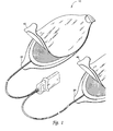
- FIG. 1 is a perspective view of an electrode pad system of this invention.
- FIG. 2 is an expanded cross-section of the electrode pad 10 shown in FIG 1.
- FIG. 3 is cross-section of an alternative embodiment of the electrode pad of FIG. 1 having a gripper 50 .
- FIG. 4A is a perspective view of the electrode pad shown in FIG 3.
- FIG. 4B is a perspective view of an alternate embodiment of the electrode pad shown in FIG 3.
- FIG. 1 is a perspective view of an electrode pad system 10 of this invention.
- the electrode pad system is comprised of two components; the first component being the electrode layer 20 and the second component being the releasing layer 40 .
- the actual construction of the two components is shown in more detail in FIG. 2.
- An advantage of this two-part construction is that it streamlines the use of the electrode to two steps: deployment and attachment. Thus, the electrode is deployed with one motion prior to applying the electrode to the victim. This construction eliminates additional steps, such as opening the packaging and removing the electrodes prior to applying the electrodes to the victim.
- FIG. 2 is an expanded cross-section of the electrode system 10 shown in FIG. 1.
- One side of each component ( 20, 40 ) forms a non-conductive outer sealing layer ( 22, 42 ).
- the outer sealing layer is a coated outer sealing layer formed from heat sealing material, such as polyethylene coated polyester or polyethylene coated foil.
- the electrode layer 20 is formed from the outer sealing layer 22 adhered to a non-conductive layer 28 with and adhesive layer 34 .
- An electrode disk 24 is adhered to the non-conductive layer of the outer sealing layer using an appropriate adhesive.
- the electrode disk 24 is formed of a suitable conductive material such as 2 mil tin and is attached to the interior surface of the outer sealing layer 22 with a suitable medical grade adhesive.
- the electrode disks are electrically connected to a lead wire 30 between the non-conductive sealing layer and the electrode disk on the upper surface of the electrode disk.
- the lower surface of the electrode disk is covered with a layer of conductive gel 26.
- a suitable conductive gel would be, for example, RG 63T hydrogel.
- the conductive gel has adhesive qualities that enable the gel to adhere to the skin of the victim.
- the electrode layer may be formed so that one end forms a pull tab 32 .
- the electrode is connected to the lead wire 30 which is connected to an electrode connector (shown in FIG. 1) or directly connected to the defibrillator.
- the lead wire 30 may be attached to a ring terminal prior to attaching to the electrode disk 24 .
- a washer may be provided between the ring terminal and the electrode disk 24 to improve the electrical connection.
- an insulating disk may be provided between the electrode disk 24 and the washer.
- the releasing layer 40 is formed from an outer sealing layer 42 which is adhered to a non-conductive layer 46 with the use of an appropriate adhesive 44 .
- the non-conductive layer is formed of a silicon coated polypropylene impregnated material.
- the releasing layer 40 is formed so that one end forms a pull tab 48 thus allowing the electrode conductive surface to be exposed with a single pulling motion.
- FIG. 3 is a cross-section of an alternative embodiment of the electrode system 10 shown in FIG. 1.
- the electrode system includes a gripper 50 attached to the outer layer of the electrode layer 20 with the use of an appropriate adhesive.
- the gripper 50 enables the user to firmly grasp the electrode layer 20 while pulling the pull-tab 48 of the releasing layer.
- the gripper 50 is provided to improve the user's ability to quickly release the electrode layer 20 when deploying the electrode.
- the gripper 50 includes a cylindrical grip 52 formed integrally with a flattened section. The flattened side of the gripper 50 is adhered to the outer surface of the sealing layer 22 .
- FIGS. 4A-B shows an alternative embodiment of the electrode system 10 shown in FIGS. 1 and 3.
- the gripper 50 is comprised of a conformable layer 50, 60 that enables the user to firmly and easily grip the electrode layer 20 while removing the releasing layer 40.
- the conformable layer is formed of a suitably flexible material, such as medium density polyethylene foam.
- the conformable layer 50, 60 may also have grooves, or channels, along its length in at least one direction.
- the conformable layer may be formed from several smaller pieces of foam positioned so that a segmented conformable layer is formed.
- the conformable layer 60 is manufactured from a single piece of foam with grooves, or channels, along its length in two directions, as shown in FIG. 4B.
- the conformable layer 60 is flat on one side thus enabling the conformable layer 60 to adhere to the exterior surface of the sealing layer.
- the exposed surface of the conformable layer 60 is curved on one side so that it fits within the hand of the user.
- the conformable layer 60 also improves the user's ability to apply the electrode pad.
- the user holds the pull tab 28 of the electrode layer 20 in one hand while pulling on the pull tab 48 of the releasing layer 40 with the other hand.
- the hydrogel layer 26 is exposed and applied directly to the victim's chest. The actual site of electrode placement will depend upon the protocol followed by the user.
- the user grips the gripper 50 in one hand while pulling on the pull tab 48 of the releasing layer 40 with the other hand.
- the hydrogel layer 26 is exposed and applied directly to the victim's chest.
- the user grips the conformable layer 50, 60 in one hand while pulling on the pull tab 48 with the other hand. Again, upon pulling the two layers apart, the hydrogel layer 26 is exposed and applied directly to the victim's chest.
Abstract
Description
- This invention relates generally to medical electrode systems and, in particular, to an independently deployable sealed defibrillator electrode for use with an automatic or semi-automatic external defibrillator (AED). The invention also relates to the method of use thereof.
- One frequent consequence of heart attacks is the development of cardiac arrest associated with heart arrhythmias, such as ventricular fibrillation ("VF"). VF is caused by an abnormal and very fast electrical activity in the heart. During VF the heart cannot pump blood effectively. VF may be treated by applying an electric shock to the patient's heart through the use of a defibrillator. Defibrillation clears the heart of the abnormal electrical activity by creating a momentary asystole, thus giving the heart's natural pacemaker areas an opportunity to restore normal function. Because blood no longer pumps effectively during VF, the chance of surviving a heart attack decreases with time after the attack. Quick response by administering a defibrillating shock as soon as possible after the onset of VF is therefore often critically important.
- Increasing the number of potential defibrillator operators who are trained in the proper use of an external defibrillator increases the likelihood that a trained defibrillator operator will be available during an emergency and thus could ultimately reduce the defibrillator deployment time. As the number of potential operators increases, however, the frequency with which each operator uses the skills developed during training decreases. Depending upon the amount of time since the defibrillator operator last used a defibrillator, review of electrode placement instructions will likely be required to determine correct placement of the electrode pads. Failure to apply the electrode pads correctly can reduce the amount of energy that is applied to the myocardium. Misapplied electrodes can allow the current to flow along the chest wall, thus missing the heart, and result in a failure of the defibrillation shock. Reviewing pad placement, while necessary, delays the speed with which defibrillation can be performed on the patient. With every second that passes, the likelihood of successfully restoring the patient's heart to a normal sinus rhythm decreases. Therefore, every step in the deployment and use of a defibrillator that can be streamlined is critical.
- One time saving gain has been the development of electrode pads that eliminate the step of attaching electrode pads to the cable, and, for the most part, eliminate the need to untangle the cable. Morgan describes an example of such an electrode system in U.S. Patent 5,466,244 for "Defibrillator Electrode System". Other electrode pad designs are known in the art. However, notwithstanding these improvements, electrode deployment and placement is still the most time consuming and difficult step in using an AED.
- Currently available defibrillator electrode pads used with AEDs use two adhesive electrode pads adhered to a liner. Additionally, the electrodes are located within a heat sealed pouch. When the electrode pads are deployed during an emergency, the user must, at a minimum, open the bag and then peel the electrodes off the liner prior to attaching the electrodes to the patient. [See, e.g., Zoll stat •padzTM.] Where the liner is not part of the bag, the user must also remove the liner from the bag prior to removing the electrodes. [See, e.g., Heartstream® ForeRunner® electrodes and Physio-Control® Fast-Patch® electrodes.] As a result, a minimum of two to three steps is required to deploy the electrode prior to attaching the electrodes to the victim. The more steps required to deploy the electrodes, the longer the victim must wait for the defibrillating shock.
- Another problem with deploying electrodes stems from the fact that they can be awkward to use. For example, the electrodes can fold upon itself requiring the user to spend time unfolding the electrode.
- What is needed is an easy to use electrode system that enables a rescuer to quickly and accurately apply the electrode pads to a victim of sudden cardiac arrest.
- This invention is directed to an electrode system comprising an electrode layer and a releasing layer which are hermetically sealed together. Each layer contains a pull-tab or gripper for allowing the user to deploy an electrode on the electrode layer in one step by pulling apart the two layers.
- This invention is also directed to a method of using an electrode system of the invention wherein the electrode is deployed in one step by pulling the electrode layer and the releasing layer apart.
- FIG. 1 is a perspective view of an electrode pad system of this invention.
- FIG. 2 is an expanded cross-section of the
electrode pad 10 shown in FIG 1. - FIG. 3 is cross-section of an alternative embodiment of the electrode pad of FIG. 1 having a
gripper 50. - FIG. 4A is a perspective view of the electrode pad shown in FIG 3.
- FIG. 4B is a perspective view of an alternate embodiment of the electrode pad shown in FIG 3.
- FIG. 1 is a perspective view of an
electrode pad system 10 of this invention. The electrode pad system is comprised of two components; the first component being theelectrode layer 20 and the second component being the releasinglayer 40. The actual construction of the two components is shown in more detail in FIG. 2. An advantage of this two-part construction is that it streamlines the use of the electrode to two steps: deployment and attachment. Thus, the electrode is deployed with one motion prior to applying the electrode to the victim. This construction eliminates additional steps, such as opening the packaging and removing the electrodes prior to applying the electrodes to the victim. - FIG. 2 is an expanded cross-section of the
electrode system 10 shown in FIG. 1. One side of each component (20, 40) forms a non-conductive outer sealing layer (22, 42). In a preferred embodiment, the outer sealing layer is a coated outer sealing layer formed from heat sealing material, such as polyethylene coated polyester or polyethylene coated foil. - The
electrode layer 20 is formed from theouter sealing layer 22 adhered to anon-conductive layer 28 with andadhesive layer 34. Anelectrode disk 24 is adhered to the non-conductive layer of the outer sealing layer using an appropriate adhesive. Theelectrode disk 24 is formed of a suitable conductive material such as 2 mil tin and is attached to the interior surface of theouter sealing layer 22 with a suitable medical grade adhesive. The electrode disks are electrically connected to alead wire 30 between the non-conductive sealing layer and the electrode disk on the upper surface of the electrode disk. The lower surface of the electrode disk is covered with a layer ofconductive gel 26. A suitable conductive gel would be, for example, RG 63T hydrogel. The conductive gel has adhesive qualities that enable the gel to adhere to the skin of the victim. As will be appreciated by those skilled in the art, other gels may be used without departing from the scope of the invention. Additionally, the electrode layer may be formed so that one end forms apull tab 32. In a preferred embodiment, the electrode is connected to thelead wire 30 which is connected to an electrode connector (shown in FIG. 1) or directly connected to the defibrillator. - Additionally, the
lead wire 30 may be attached to a ring terminal prior to attaching to theelectrode disk 24. Further, a washer may be provided between the ring terminal and theelectrode disk 24 to improve the electrical connection. Finally, an insulating disk may be provided between theelectrode disk 24 and the washer. - The releasing
layer 40 is formed from anouter sealing layer 42 which is adhered to anon-conductive layer 46 with the use of anappropriate adhesive 44. In a preferred embodiment, the non-conductive layer is formed of a silicon coated polypropylene impregnated material. The releasinglayer 40 is formed so that one end forms apull tab 48 thus allowing the electrode conductive surface to be exposed with a single pulling motion. - FIG. 3 is a cross-section of an alternative embodiment of the
electrode system 10 shown in FIG. 1. In addition to the releasinglayer 40 and theelectrode layer 20 discussed above with respect to FIG. 2, the electrode system includes agripper 50 attached to the outer layer of theelectrode layer 20 with the use of an appropriate adhesive. Thegripper 50 enables the user to firmly grasp theelectrode layer 20 while pulling the pull-tab 48 of the releasing layer. Thegripper 50 is provided to improve the user's ability to quickly release theelectrode layer 20 when deploying the electrode. In the embodiment shown in FIG. 3, thegripper 50 includes acylindrical grip 52 formed integrally with a flattened section. The flattened side of thegripper 50 is adhered to the outer surface of thesealing layer 22. - FIGS. 4A-B shows an alternative embodiment of the
electrode system 10 shown in FIGS. 1 and 3. In the embodiment shown in FIG. 4A, thegripper 50 is comprised of aconformable layer electrode layer 20 while removing the releasinglayer 40. In a preferred embodiment, the conformable layer is formed of a suitably flexible material, such as medium density polyethylene foam. Theconformable layer conformable layer 60 is manufactured from a single piece of foam with grooves, or channels, along its length in two directions, as shown in FIG. 4B. In an even more preferred embodiment, theconformable layer 60 is flat on one side thus enabling theconformable layer 60 to adhere to the exterior surface of the sealing layer. The exposed surface of theconformable layer 60 is curved on one side so that it fits within the hand of the user. Theconformable layer 60 also improves the user's ability to apply the electrode pad. - In operation of the first embodiment shown in FIG. 1, the user holds the
pull tab 28 of theelectrode layer 20 in one hand while pulling on thepull tab 48 of the releasinglayer 40 with the other hand. Upon pulling the two layers apart, thehydrogel layer 26 is exposed and applied directly to the victim's chest. The actual site of electrode placement will depend upon the protocol followed by the user. - In operation of the second embodiment of the electrode system shown in FIGS. 3, the user grips the
gripper 50 in one hand while pulling on thepull tab 48 of the releasinglayer 40 with the other hand. As with the previous embodiment, upon pulling the two layers apart, thehydrogel layer 26 is exposed and applied directly to the victim's chest. - In operation of the third embodiment of the
electrode system 10 shown in FIGS. 4A-B, the user grips theconformable layer pull tab 48 with the other hand. Again, upon pulling the two layers apart, thehydrogel layer 26 is exposed and applied directly to the victim's chest. - The embodiments described above are for purposes of illustrating the invention and are not meant to limit the scope of the invention. It is contemplated that various modifications may be made without deviating from the spirit and scope of the invention and will be apparent to persons skilled in the art. All references cited herein are incorporated herein by reference in their entirety.
Claims (10)
- An electrode system 10 comprising, in sealed combination,an electrode layer 20; anda releasing layer 40.
- The electrode system 10 of claim 1 wherein the electrode layer 20 is further comprised of a hydrogel layer 26 and an electrode disk 24 adhered to a sealing layer 22.
- The electrode system 10 of claim 2 wherein the hydrogel layer 26 is formed from RG 63T hydrogel.
- The electrode system 10 of claim 2 wherein the electrode disk 24 is a 2 mil tin disk.
- The electrode system 10 of claim 1 wherein the electrode layer 20 and the releasing layer 40 are hermetically sealed.
- The electrode system 10 of claim 1 wherein the releasing layer 40 is further comprised of a non-stick layer 46 adhered to an outer sealing layer 42.
- The electrode system 10 of claim 1 wherein a gripper 52 is adhered to one side of the electrode layer 20.
- The electrode system 10 of claim 7 wherein the gripper 52 is a conformable segmented layer 60.
- A method of using an electrode system 10 comprising:holding a pull tab 48 of a releasing layer 40 in one hand; andpulling a gripper 60 of an electrode layer 20 with another hand to expose an electrode surface on the electrode layer 20.
- The method of claim 9 further comprising the following step:
applying the electrode to a patient's chest.
Applications Claiming Priority (2)
| Application Number | Priority Date | Filing Date | Title |
|---|---|---|---|
| US09/145,168 US6272385B1 (en) | 1998-09-01 | 1998-09-01 | Independently deployable sealed defibrillator electrode pad and method of use |
| US145168 | 1998-09-01 |
Publications (3)
| Publication Number | Publication Date |
|---|---|
| EP0983775A2 true EP0983775A2 (en) | 2000-03-08 |
| EP0983775A3 EP0983775A3 (en) | 2000-12-06 |
| EP0983775B1 EP0983775B1 (en) | 2005-06-01 |
Family
ID=22511897
Family Applications (1)
| Application Number | Title | Priority Date | Filing Date |
|---|---|---|---|
| EP99306528A Expired - Lifetime EP0983775B1 (en) | 1998-09-01 | 1999-08-19 | Independently deployable sealed defibrillator electrode pad and method of use |
Country Status (4)
| Country | Link |
|---|---|
| US (1) | US6272385B1 (en) |
| EP (1) | EP0983775B1 (en) |
| JP (2) | JP2000070381A (en) |
| DE (1) | DE69925550T2 (en) |
Cited By (7)
| Publication number | Priority date | Publication date | Assignee | Title |
|---|---|---|---|---|
| WO2001091850A1 (en) * | 2000-05-30 | 2001-12-06 | Michael Peter Wildon | Cardiac stimulation apparatus |
| EP1365973A2 (en) * | 2001-02-27 | 2003-12-03 | Philips Electronics North America Corporation | Method and package for increasing electrode shelf life |
| WO2005009530A1 (en) * | 2003-07-18 | 2005-02-03 | 3M Innovative Properties Company | Biomedical electrode with current spreading layer |
| WO2006046160A1 (en) * | 2004-10-29 | 2006-05-04 | Koninklijke Philips Electronics, N.V. | Electrode and enclosure for cardiac monitoring and treatment |
| WO2012131536A3 (en) * | 2011-03-28 | 2013-01-03 | Koninklijke Philips Electronics N.V. | Defibrillator electrode pad with two peel tabs |
| US8676291B2 (en) | 2006-11-13 | 2014-03-18 | Koninklijke Philips N.V. | Halibut release liner for a defibrillator electrode pad |
| WO2014070123A1 (en) * | 2012-11-01 | 2014-05-08 | Ulusahin Omer Sezgin | A protected electrode with enhanced body adhesion and insulation characteristics |
Families Citing this family (71)
| Publication number | Priority date | Publication date | Assignee | Title |
|---|---|---|---|---|
| US7146212B2 (en) | 2000-09-18 | 2006-12-05 | Cameron Health, Inc. | Anti-bradycardia pacing for a subcutaneous implantable cardioverter-defibrillator |
| US20020035381A1 (en) * | 2000-09-18 | 2002-03-21 | Cameron Health, Inc. | Subcutaneous electrode with improved contact shape for transthoracic conduction |
| US7069080B2 (en) | 2000-09-18 | 2006-06-27 | Cameron Health, Inc. | Active housing and subcutaneous electrode cardioversion/defibrillating system |
| US6754528B2 (en) | 2001-11-21 | 2004-06-22 | Cameraon Health, Inc. | Apparatus and method of arrhythmia detection in a subcutaneous implantable cardioverter/defibrillator |
| US6721597B1 (en) | 2000-09-18 | 2004-04-13 | Cameron Health, Inc. | Subcutaneous only implantable cardioverter defibrillator and optional pacer |
| US6560485B2 (en) | 2001-03-27 | 2003-05-06 | Koninklijke Philips Electronics N.V. | Four contact identification defibrillator electrode system |
| US7027877B2 (en) * | 2001-08-23 | 2006-04-11 | Zoll Medical Corporation | Method of applying defibrilator electrode pad with folded release sheet |
| US7069074B2 (en) | 2001-11-07 | 2006-06-27 | Medtronic Emergency Response Systems, Inc. | Easy-to-use electrode and package |
| US20040143301A1 (en) * | 2003-01-22 | 2004-07-22 | Christian Hunt | Skin electrodes with design thereon |
| JP5290571B2 (en) * | 2004-03-23 | 2013-09-18 | コーニンクレッカ フィリップス エレクトロニクス エヌ ヴィ | Self-storage medical electrode |
| US7668604B2 (en) * | 2004-06-16 | 2010-02-23 | Conmed Corporation | Packaging for medical pads and electrodes |
| US20060142831A1 (en) * | 2004-12-28 | 2006-06-29 | Medtronic Emergency Response Systems, Inc. | Limited use ECG electrode set |
| WO2007127266A2 (en) | 2006-04-27 | 2007-11-08 | Covidien Ag | Electrode pad packaging systems and methods |
| US7869855B2 (en) * | 2006-09-28 | 2011-01-11 | Tyco Healthcare Group Lp | Medical apparatus with releasable applicator |
| WO2008089186A1 (en) * | 2007-01-15 | 2008-07-24 | Oliver Products Company | Cover with circuit |
| US7816412B2 (en) * | 2007-02-23 | 2010-10-19 | Conmed Corporation | Electrically conductive hydrogels |
| RU2556969C2 (en) * | 2009-09-28 | 2015-07-20 | Конинклейке Филипс Электроникс Н.В. | Defibrillator with preliminarily connected electrode pads with reduced sensitivity to mistaken asystole identification |
| WO2011096532A1 (en) | 2010-02-05 | 2011-08-11 | 国立大学法人秋田大学 | Solid electrolyte and electrochemical element |
| US8613708B2 (en) | 2010-10-08 | 2013-12-24 | Cardiac Science Corporation | Ambulatory electrocardiographic monitor with jumpered sensing electrode |
| US9037477B2 (en) | 2010-10-08 | 2015-05-19 | Cardiac Science Corporation | Computer-implemented system and method for evaluating ambulatory electrocardiographic monitoring of cardiac rhythm disorders |
| US8239012B2 (en) | 2010-10-08 | 2012-08-07 | Cardiac Science Corporation | Microcontrolled electrocardiographic monitoring circuit with differential voltage encoding |
| US20120089000A1 (en) | 2010-10-08 | 2012-04-12 | Jon Mikalson Bishay | Ambulatory Electrocardiographic Monitor For Providing Ease Of Use In Women And Method Of Use |
| US9881521B2 (en) * | 2011-01-17 | 2018-01-30 | Prestan Products Llc | Manikin sensing pads and liners in an AED training system |
| US10279189B2 (en) | 2013-06-14 | 2019-05-07 | Cardiothrive, Inc. | Wearable multiphasic cardioverter defibrillator system and method |
| US9393402B2 (en) * | 2013-08-12 | 2016-07-19 | Physio-Control, Inc. | Electrode tray with integrated connector and storage for wires |
| US10624551B2 (en) | 2013-09-25 | 2020-04-21 | Bardy Diagnostics, Inc. | Insertable cardiac monitor for use in performing long term electrocardiographic monitoring |
| US9655538B2 (en) | 2013-09-25 | 2017-05-23 | Bardy Diagnostics, Inc. | Self-authenticating electrocardiography monitoring circuit |
| US9717433B2 (en) | 2013-09-25 | 2017-08-01 | Bardy Diagnostics, Inc. | Ambulatory electrocardiography monitoring patch optimized for capturing low amplitude cardiac action potential propagation |
| US10433748B2 (en) | 2013-09-25 | 2019-10-08 | Bardy Diagnostics, Inc. | Extended wear electrocardiography and physiological sensor monitor |
| US10165946B2 (en) | 2013-09-25 | 2019-01-01 | Bardy Diagnostics, Inc. | Computer-implemented system and method for providing a personal mobile device-triggered medical intervention |
| WO2015048194A1 (en) | 2013-09-25 | 2015-04-02 | Bardy Diagnostics, Inc. | Self-contained personal air flow sensing monitor |
| US9433380B1 (en) | 2013-09-25 | 2016-09-06 | Bardy Diagnostics, Inc. | Extended wear electrocardiography patch |
| US20190167139A1 (en) | 2017-12-05 | 2019-06-06 | Gust H. Bardy | Subcutaneous P-Wave Centric Insertable Cardiac Monitor For Long Term Electrocardiographic Monitoring |
| US9545204B2 (en) | 2013-09-25 | 2017-01-17 | Bardy Diagnostics, Inc. | Extended wear electrocardiography patch |
| US9619660B1 (en) | 2013-09-25 | 2017-04-11 | Bardy Diagnostics, Inc. | Computer-implemented system for secure physiological data collection and processing |
| US10433751B2 (en) | 2013-09-25 | 2019-10-08 | Bardy Diagnostics, Inc. | System and method for facilitating a cardiac rhythm disorder diagnosis based on subcutaneous cardiac monitoring data |
| US10463269B2 (en) | 2013-09-25 | 2019-11-05 | Bardy Diagnostics, Inc. | System and method for machine-learning-based atrial fibrillation detection |
| US10667711B1 (en) | 2013-09-25 | 2020-06-02 | Bardy Diagnostics, Inc. | Contact-activated extended wear electrocardiography and physiological sensor monitor recorder |
| US9717432B2 (en) | 2013-09-25 | 2017-08-01 | Bardy Diagnostics, Inc. | Extended wear electrocardiography patch using interlaced wire electrodes |
| US10799137B2 (en) | 2013-09-25 | 2020-10-13 | Bardy Diagnostics, Inc. | System and method for facilitating a cardiac rhythm disorder diagnosis with the aid of a digital computer |
| US9615763B2 (en) | 2013-09-25 | 2017-04-11 | Bardy Diagnostics, Inc. | Ambulatory electrocardiography monitor recorder optimized for capturing low amplitude cardiac action potential propagation |
| US9737224B2 (en) | 2013-09-25 | 2017-08-22 | Bardy Diagnostics, Inc. | Event alerting through actigraphy embedded within electrocardiographic data |
| US9408545B2 (en) | 2013-09-25 | 2016-08-09 | Bardy Diagnostics, Inc. | Method for efficiently encoding and compressing ECG data optimized for use in an ambulatory ECG monitor |
| US9345414B1 (en) | 2013-09-25 | 2016-05-24 | Bardy Diagnostics, Inc. | Method for providing dynamic gain over electrocardiographic data with the aid of a digital computer |
| US10820801B2 (en) | 2013-09-25 | 2020-11-03 | Bardy Diagnostics, Inc. | Electrocardiography monitor configured for self-optimizing ECG data compression |
| US9408551B2 (en) | 2013-11-14 | 2016-08-09 | Bardy Diagnostics, Inc. | System and method for facilitating diagnosis of cardiac rhythm disorders with the aid of a digital computer |
| US10806360B2 (en) | 2013-09-25 | 2020-10-20 | Bardy Diagnostics, Inc. | Extended wear ambulatory electrocardiography and physiological sensor monitor |
| US9775536B2 (en) | 2013-09-25 | 2017-10-03 | Bardy Diagnostics, Inc. | Method for constructing a stress-pliant physiological electrode assembly |
| US9655537B2 (en) | 2013-09-25 | 2017-05-23 | Bardy Diagnostics, Inc. | Wearable electrocardiography and physiology monitoring ensemble |
| US11213237B2 (en) | 2013-09-25 | 2022-01-04 | Bardy Diagnostics, Inc. | System and method for secure cloud-based physiological data processing and delivery |
| US11723575B2 (en) | 2013-09-25 | 2023-08-15 | Bardy Diagnostics, Inc. | Electrocardiography patch |
| US9364155B2 (en) | 2013-09-25 | 2016-06-14 | Bardy Diagnostics, Inc. | Self-contained personal air flow sensing monitor |
| US9433367B2 (en) | 2013-09-25 | 2016-09-06 | Bardy Diagnostics, Inc. | Remote interfacing of extended wear electrocardiography and physiological sensor monitor |
| US9700227B2 (en) | 2013-09-25 | 2017-07-11 | Bardy Diagnostics, Inc. | Ambulatory electrocardiography monitoring patch optimized for capturing low amplitude cardiac action potential propagation |
| US10888239B2 (en) | 2013-09-25 | 2021-01-12 | Bardy Diagnostics, Inc. | Remote interfacing electrocardiography patch |
| US10736529B2 (en) | 2013-09-25 | 2020-08-11 | Bardy Diagnostics, Inc. | Subcutaneous insertable electrocardiography monitor |
| US10251576B2 (en) | 2013-09-25 | 2019-04-09 | Bardy Diagnostics, Inc. | System and method for ECG data classification for use in facilitating diagnosis of cardiac rhythm disorders with the aid of a digital computer |
| US10736531B2 (en) | 2013-09-25 | 2020-08-11 | Bardy Diagnostics, Inc. | Subcutaneous insertable cardiac monitor optimized for long term, low amplitude electrocardiographic data collection |
| US9504423B1 (en) | 2015-10-05 | 2016-11-29 | Bardy Diagnostics, Inc. | Method for addressing medical conditions through a wearable health monitor with the aid of a digital computer |
| USD831833S1 (en) | 2013-11-07 | 2018-10-23 | Bardy Diagnostics, Inc. | Extended wear electrode patch |
| USD717955S1 (en) | 2013-11-07 | 2014-11-18 | Bardy Diagnostics, Inc. | Electrocardiography monitor |
| USD892340S1 (en) | 2013-11-07 | 2020-08-04 | Bardy Diagnostics, Inc. | Extended wear electrode patch |
| USD793566S1 (en) | 2015-09-10 | 2017-08-01 | Bardy Diagnostics, Inc. | Extended wear electrode patch |
| USD801528S1 (en) | 2013-11-07 | 2017-10-31 | Bardy Diagnostics, Inc. | Electrocardiography monitor |
| USD744659S1 (en) | 2013-11-07 | 2015-12-01 | Bardy Diagnostics, Inc. | Extended wear electrode patch |
| US10004894B2 (en) | 2014-11-19 | 2018-06-26 | Intermountain Intellectual Asset Management, Llc | Defibrillators with multi-pad electrodes and related methods |
| USD766447S1 (en) | 2015-09-10 | 2016-09-13 | Bardy Diagnostics, Inc. | Extended wear electrode patch |
| US11096579B2 (en) | 2019-07-03 | 2021-08-24 | Bardy Diagnostics, Inc. | System and method for remote ECG data streaming in real-time |
| US11116451B2 (en) | 2019-07-03 | 2021-09-14 | Bardy Diagnostics, Inc. | Subcutaneous P-wave centric insertable cardiac monitor with energy harvesting capabilities |
| US11696681B2 (en) | 2019-07-03 | 2023-07-11 | Bardy Diagnostics Inc. | Configurable hardware platform for physiological monitoring of a living body |
| USD985781S1 (en) * | 2020-08-19 | 2023-05-09 | Morari, Llc | Electrode stimulation applicator patch |
Citations (1)
| Publication number | Priority date | Publication date | Assignee | Title |
|---|---|---|---|---|
| US5466244A (en) | 1993-05-18 | 1995-11-14 | Heartstream, Inc. | Defibrillator electrode system |
Family Cites Families (24)
| Publication number | Priority date | Publication date | Assignee | Title |
|---|---|---|---|---|
| CH636034A5 (en) | 1979-03-17 | 1983-05-13 | Maag Zahnraeder & Maschinen Ag | DRESSING DEVICE FOR A PLATE-SHAPED GRINDING WHEEL ON A TOOTHED FRAME GRINDING MACHINE. |
| US4895169A (en) | 1980-08-08 | 1990-01-23 | Darox Corporation | Disposable non-invasive stimulating electrode set |
| US4852585A (en) | 1980-08-08 | 1989-08-01 | Darox Corporation | Tin-stannous chloride electrode element |
| US4419998A (en) | 1980-08-08 | 1983-12-13 | R2 Corporation | Physiological electrode systems |
| US4653503A (en) | 1983-11-23 | 1987-03-31 | R2 Corporation | Physiological electrodes for use with magnetic connector |
| US4681112A (en) | 1985-01-08 | 1987-07-21 | Physio-Control Corporation | Medical instrument including electrodes adapted for right and left-handed use |
| US4779630A (en) * | 1987-09-18 | 1988-10-25 | Katecho, Inc. | Defibrillator pad assembly and method for using same |
| US4979517A (en) | 1988-02-01 | 1990-12-25 | Physio-Control Corporation | Disposable stimulation electrode with long shelf life and improved current density profile |
| US5080099A (en) | 1988-08-26 | 1992-01-14 | Cardiotronics, Inc. | Multi-pad, multi-function electrode |
| US4955381A (en) | 1988-08-26 | 1990-09-11 | Cardiotronics, Inc. | Multi-pad, multi-function electrode |
| US5150708A (en) * | 1990-12-03 | 1992-09-29 | Spacelabs, Inc. | Tabbed defibrillator electrode pad |
| US5137458A (en) | 1991-01-11 | 1992-08-11 | Physio-Control Corporation | Electrode placement training system |
| WO1993000857A1 (en) | 1991-07-12 | 1993-01-21 | Ludlow Corporation | Biomedical electrode |
| DE4238263A1 (en) * | 1991-11-15 | 1993-05-19 | Minnesota Mining & Mfg | Adhesive comprising hydrogel and crosslinked polyvinyl:lactam - is used in electrodes for biomedical application providing low impedance and good mechanical properties when water and/or moisture is absorbed from skin |
| US5330526A (en) | 1992-05-01 | 1994-07-19 | Zmd Corporation | Combined defibrillation and pacing electrode |
| US5984102A (en) * | 1992-09-24 | 1999-11-16 | Survivalink Corporation | Medical electrode packaging technology |
| US5506059A (en) * | 1993-05-14 | 1996-04-09 | Minnesota Mining And Manufacturing Company | Metallic films and articles using same |
| US5520683A (en) * | 1994-05-16 | 1996-05-28 | Physiometrix, Inc. | Medical electrode and method |
| US5456710A (en) * | 1994-06-30 | 1995-10-10 | Physio-Control Corporation | Vented electrode |
| US5571165A (en) | 1995-12-08 | 1996-11-05 | Ferrari; R. Keith | X-ray transmissive transcutaneous stimulating electrode |
| US5827184A (en) * | 1995-12-29 | 1998-10-27 | Minnesota Mining And Manufacturing Company | Self-packaging bioelectrodes |
| US6135953A (en) * | 1996-01-25 | 2000-10-24 | 3M Innovative Properties Company | Multi-functional biomedical electrodes |
| US5700281A (en) * | 1996-06-04 | 1997-12-23 | Survivalink Corporation | Stage and state monitoring automated external defibrillator |
| JPH1095962A (en) * | 1996-09-25 | 1998-04-14 | Nitto Denko Corp | Electroconductive adhesive composition, electroconductive pad obtained from the same composition and medical electrode using the same |
-
1998
- 1998-09-01 US US09/145,168 patent/US6272385B1/en not_active Expired - Lifetime
-
1999
- 1999-08-19 EP EP99306528A patent/EP0983775B1/en not_active Expired - Lifetime
- 1999-08-19 DE DE69925550T patent/DE69925550T2/en not_active Expired - Lifetime
- 1999-08-25 JP JP11238153A patent/JP2000070381A/en active Pending
-
2008
- 2008-01-28 JP JP2008016026A patent/JP2008110242A/en active Pending
Patent Citations (1)
| Publication number | Priority date | Publication date | Assignee | Title |
|---|---|---|---|---|
| US5466244A (en) | 1993-05-18 | 1995-11-14 | Heartstream, Inc. | Defibrillator electrode system |
Cited By (17)
| Publication number | Priority date | Publication date | Assignee | Title |
|---|---|---|---|---|
| GB2379395A (en) * | 2000-05-30 | 2003-03-12 | Michael Peter Wildon | Cardiac stimulation apparatus |
| GB2379395B (en) * | 2000-05-30 | 2004-09-15 | Michael Peter Wildon | Cardiac stimulation apparatus |
| WO2001091850A1 (en) * | 2000-05-30 | 2001-12-06 | Michael Peter Wildon | Cardiac stimulation apparatus |
| EP1365973A2 (en) * | 2001-02-27 | 2003-12-03 | Philips Electronics North America Corporation | Method and package for increasing electrode shelf life |
| EP1365973A4 (en) * | 2001-02-27 | 2007-01-24 | Koninkl Philips Electronics Nv | Method and package for increasing electrode shelf life |
| US7187985B2 (en) | 2003-07-18 | 2007-03-06 | 3M Innovative Properties Company | Biomedical electrode with current spreading layer |
| WO2005009530A1 (en) * | 2003-07-18 | 2005-02-03 | 3M Innovative Properties Company | Biomedical electrode with current spreading layer |
| CN101052438B (en) * | 2004-10-29 | 2012-06-06 | 皇家飞利浦电子股份有限公司 | Electrode assembly for cardiac monitoring and treatment |
| WO2006046160A1 (en) * | 2004-10-29 | 2006-05-04 | Koninklijke Philips Electronics, N.V. | Electrode and enclosure for cardiac monitoring and treatment |
| US9002473B2 (en) | 2004-10-29 | 2015-04-07 | Koninklijke Philips N.V. | Electrode and enclosure for cardiac monitoring and treatment |
| US8676291B2 (en) | 2006-11-13 | 2014-03-18 | Koninklijke Philips N.V. | Halibut release liner for a defibrillator electrode pad |
| US8818529B2 (en) | 2006-11-13 | 2014-08-26 | Koninklijke Philips N.V. | Halibut release liner for a defibrillator electrode pad |
| WO2012131536A3 (en) * | 2011-03-28 | 2013-01-03 | Koninklijke Philips Electronics N.V. | Defibrillator electrode pad with two peel tabs |
| CN103476455A (en) * | 2011-03-28 | 2013-12-25 | 皇家飞利浦有限公司 | Defibrillator electrode pad with two peel tabs |
| US8965533B2 (en) | 2011-03-28 | 2015-02-24 | Koninklijke Philips N.V. | Defibrillator electrode pad with two peel tabs |
| CN103476455B (en) * | 2011-03-28 | 2015-12-02 | 皇家飞利浦有限公司 | There is the defibrillator electrode pad that two are peeled off tab |
| WO2014070123A1 (en) * | 2012-11-01 | 2014-05-08 | Ulusahin Omer Sezgin | A protected electrode with enhanced body adhesion and insulation characteristics |
Also Published As
| Publication number | Publication date |
|---|---|
| US6272385B1 (en) | 2001-08-07 |
| EP0983775A3 (en) | 2000-12-06 |
| EP0983775B1 (en) | 2005-06-01 |
| DE69925550D1 (en) | 2005-07-07 |
| JP2000070381A (en) | 2000-03-07 |
| JP2008110242A (en) | 2008-05-15 |
| DE69925550T2 (en) | 2006-04-27 |
Similar Documents
| Publication | Publication Date | Title |
|---|---|---|
| US6272385B1 (en) | Independently deployable sealed defibrillator electrode pad and method of use | |
| US6178357B1 (en) | Electrode pad system and defibrillator electrode pad that reduces the risk of peripheral shock | |
| US5466244A (en) | Defibrillator electrode system | |
| US5951598A (en) | Electrode system | |
| US5527358A (en) | Temporary medical electrical lead | |
| US4481953A (en) | Endocardial lead having helically wound ribbon electrode | |
| RU2585731C2 (en) | Defibrillator electrode patch with two laminate tabs | |
| CA1315351C (en) | Implantable defribrillation electrodes | |
| US6134479A (en) | Electrode triad for external defibrillation | |
| US5052390A (en) | Method and apparatus for defibrillating the heart using internal esophageal electrode and external chest electrode | |
| US20080183230A1 (en) | Methods and Apparatus for Selectively Shunting Energy in an Implantable Extra-Cardiac Defibrillation Device | |
| WO2000074769A9 (en) | Cardiac shock electrode system and corresponding implantable defibrillator system | |
| US6993395B2 (en) | Skin-applied electrode pads | |
| JPH06507097A (en) | Defibrillator, temporary pacer catheter, and its implantation method | |
| NL8120182A (en) | METHOD AND APPARATUS FOR IMPLANTING A CARTRIDGE | |
| US5993219A (en) | Method and apparatus for modifying a resuscitation training mannequin | |
| CA2200288A1 (en) | Temporary, post-heart surgery cardioverting and pacing system and lead systems for use | |
| US6714824B1 (en) | Universal electrode system and methods of use and manufacture | |
| WO1982002664A1 (en) | Implantable cardiac defibrillating electrode | |
| US7596409B2 (en) | Cardiac shock electrode system and corresponding implantable defibrillator system | |
| CA1173511A (en) | Method and apparatus for implanting cardiac electrode |
Legal Events
| Date | Code | Title | Description |
|---|---|---|---|
| PUAI | Public reference made under article 153(3) epc to a published international application that has entered the european phase |
Free format text: ORIGINAL CODE: 0009012 |
|
| AK | Designated contracting states |
Kind code of ref document: A2 Designated state(s): DE GB |
|
| AX | Request for extension of the european patent |
Free format text: AL;LT;LV;MK;RO;SI |
|
| PUAL | Search report despatched |
Free format text: ORIGINAL CODE: 0009013 |
|
| AK | Designated contracting states |
Kind code of ref document: A3 Designated state(s): AT BE CH CY DE DK ES FI FR GB GR IE IT LI LU MC NL PT SE |
|
| AX | Request for extension of the european patent |
Free format text: AL;LT;LV;MK;RO;SI |
|
| RAP1 | Party data changed (applicant data changed or rights of an application transferred) |
Owner name: AGILENT TECHNOLOGIES INC |
|
| 17P | Request for examination filed |
Effective date: 20010515 |
|
| RAP1 | Party data changed (applicant data changed or rights of an application transferred) |
Owner name: AGILENT TECHNOLOGIES INC. |
|
| RAP1 | Party data changed (applicant data changed or rights of an application transferred) |
Owner name: AGILENT TECHNOLOGIES INC. A DELAWARE CORPORATION |
|
| AKX | Designation fees paid |
Free format text: DE GB |
|
| RAP1 | Party data changed (applicant data changed or rights of an application transferred) |
Owner name: AGILENT TECHNOLOGIES, INC. (A DELAWARE CORPORATION |
|
| 17Q | First examination report despatched |
Effective date: 20030603 |
|
| RAP1 | Party data changed (applicant data changed or rights of an application transferred) |
Owner name: KONINKLIJKE PHILIPS ELECTRONICS N.V. |
|
| GRAP | Despatch of communication of intention to grant a patent |
Free format text: ORIGINAL CODE: EPIDOSNIGR1 |
|
| GRAS | Grant fee paid |
Free format text: ORIGINAL CODE: EPIDOSNIGR3 |
|
| GRAA | (expected) grant |
Free format text: ORIGINAL CODE: 0009210 |
|
| AK | Designated contracting states |
Kind code of ref document: B1 Designated state(s): DE GB |
|
| REG | Reference to a national code |
Ref country code: GB Ref legal event code: FG4D |
|
| REF | Corresponds to: |
Ref document number: 69925550 Country of ref document: DE Date of ref document: 20050707 Kind code of ref document: P |
|
| PLBE | No opposition filed within time limit |
Free format text: ORIGINAL CODE: 0009261 |
|
| STAA | Information on the status of an ep patent application or granted ep patent |
Free format text: STATUS: NO OPPOSITION FILED WITHIN TIME LIMIT |
|
| 26N | No opposition filed |
Effective date: 20060302 |
|
| REG | Reference to a national code |
Ref country code: DE Ref legal event code: R082 Ref document number: 69925550 Country of ref document: DE Representative=s name: MEISSNER, BOLTE & PARTNER GBR, DE |
|
| REG | Reference to a national code |
Ref country code: DE Ref legal event code: R082 Ref document number: 69925550 Country of ref document: DE Representative=s name: MEISSNER BOLTE PATENTANWAELTE RECHTSANWAELTE P, DE Effective date: 20140328 Ref country code: DE Ref legal event code: R082 Ref document number: 69925550 Country of ref document: DE Representative=s name: MEISSNER, BOLTE & PARTNER GBR, DE Effective date: 20140328 Ref country code: DE Ref legal event code: R081 Ref document number: 69925550 Country of ref document: DE Owner name: KONINKLIJKE PHILIPS N.V., NL Free format text: FORMER OWNER: KONINKLIJKE PHILIPS ELECTRONICS N.V., EINDHOVEN, NL Effective date: 20140328 |
|
| PGFP | Annual fee paid to national office [announced via postgrant information from national office to epo] |
Ref country code: GB Payment date: 20180831 Year of fee payment: 20 |
|
| PGFP | Annual fee paid to national office [announced via postgrant information from national office to epo] |
Ref country code: DE Payment date: 20181031 Year of fee payment: 20 |
|
| REG | Reference to a national code |
Ref country code: DE Ref legal event code: R071 Ref document number: 69925550 Country of ref document: DE |
|
| REG | Reference to a national code |
Ref country code: GB Ref legal event code: PE20 Expiry date: 20190818 |
|
| PG25 | Lapsed in a contracting state [announced via postgrant information from national office to epo] |
Ref country code: GB Free format text: LAPSE BECAUSE OF EXPIRATION OF PROTECTION Effective date: 20190818 |