EP0985220B1 - Fabrication of electron-emitting device having ladder-like emitter electrode - Google Patents
Fabrication of electron-emitting device having ladder-like emitter electrode Download PDFInfo
- Publication number
- EP0985220B1 EP0985220B1 EP98924767A EP98924767A EP0985220B1 EP 0985220 B1 EP0985220 B1 EP 0985220B1 EP 98924767 A EP98924767 A EP 98924767A EP 98924767 A EP98924767 A EP 98924767A EP 0985220 B1 EP0985220 B1 EP 0985220B1
- Authority
- EP
- European Patent Office
- Prior art keywords
- electron
- emitter
- electrodes
- focusing
- layer
- Prior art date
- Legal status (The legal status is an assumption and is not a legal conclusion. Google has not performed a legal analysis and makes no representation as to the accuracy of the status listed.)
- Expired - Lifetime
Links
Images


Classifications
-
- H—ELECTRICITY
- H01—ELECTRIC ELEMENTS
- H01J—ELECTRIC DISCHARGE TUBES OR DISCHARGE LAMPS
- H01J19/00—Details of vacuum tubes of the types covered by group H01J21/00
- H01J19/02—Electron-emitting electrodes; Cathodes
- H01J19/24—Cold cathodes, e.g. field-emissive cathode
-
- H—ELECTRICITY
- H01—ELECTRIC ELEMENTS
- H01J—ELECTRIC DISCHARGE TUBES OR DISCHARGE LAMPS
- H01J9/00—Apparatus or processes specially adapted for the manufacture, installation, removal, maintenance of electric discharge tubes, discharge lamps, or parts thereof; Recovery of material from discharge tubes or lamps
- H01J9/02—Manufacture of electrodes or electrode systems
- H01J9/022—Manufacture of electrodes or electrode systems of cold cathodes
- H01J9/025—Manufacture of electrodes or electrode systems of cold cathodes of field emission cathodes
-
- H—ELECTRICITY
- H01—ELECTRIC ELEMENTS
- H01J—ELECTRIC DISCHARGE TUBES OR DISCHARGE LAMPS
- H01J3/00—Details of electron-optical or ion-optical arrangements or of ion traps common to two or more basic types of discharge tubes or lamps
- H01J3/02—Electron guns
- H01J3/021—Electron guns using a field emission, photo emission, or secondary emission electron source
- H01J3/022—Electron guns using a field emission, photo emission, or secondary emission electron source with microengineered cathode, e.g. Spindt-type
-
- H—ELECTRICITY
- H01—ELECTRIC ELEMENTS
- H01J—ELECTRIC DISCHARGE TUBES OR DISCHARGE LAMPS
- H01J2329/00—Electron emission display panels, e.g. field emission display panels
Definitions
- This invention relates to electron-emitting devices. More particularly, this invention relates to the structure and fabrication, including testing, of an electron-emitting device suitable for use in a flat-panel display of the cathode-ray tube (“CRT”) type.
- CRT cathode-ray tube
- a flat-panel CRT display basically consists of an electron-emitting device and a light-emitting device that operate at low internal pressure.
- the electron-emitting device commonly referred to as a cathode, contains electron-emissive elements that emit electrons over a wide area. The emitted electrons are directed towards light-emissive elements distributed over a corresponding area in the light-emitting device. Upon being struck by the electrons, the light-emissive elements emit light that produces an image on the viewing surface of the display.
- the electron-emissive elements are conventionally situated over generally parallel emitter electrodes that are opaque--i.e., impervious to light, typically ultraviolet ("UV”) and infrared (“IR”) light as well as visible light.
- control electrodes typically cross over, and are electrically insulated from, the emitter electrodes.
- a set of electron-emissive elements are electrically coupled to each emitter electrode where it is crossed by one of the control electrodes.
- the electron-emissive elements are exposed through openings in the control electrodes.
- a suitable voltage is applied between a control electrode and an emitter electrode, the control electrode extracts electrons from the associated electron-emissive elements.
- An anode in the light-emitting device attracts the electrons to the light-emissive elements.
- the electron-emitting device in a flat-panel CRT display commonly contains a focusing structure that helps control the trajectories of the electrons so that they largely only strike the intended light-emissive elements.
- the focusing structure normally extends above the control electrodes.
- the lateral relationship of the focusing structure to the sets of electron-emissive elements is critical to achieving high display performance.
- the opaque nature of the emitter electrodes can present an impediment to achieving the requisite lateral spacing between the focusing structure and the sets of electron-emissive elements. Accordingly, it would be desirable to configure the emitter electrodes in such as way as to facilitate controlling the lateral positions of components, such as the focusing structure, in the electron-emitting device.
- Short circuits sometime occur between the control electrodes, on one hand, and the emitter electrodes, on the other hand.
- the presence of a short circuit can have a very detrimental effect on the display's performance.
- a short circuit at the crossing between a particular control electrode and a particular emitter electrode can prevent part or all of the set of electron-emissive elements associated with those two electrodes from operating properly. It would also be desirable to have a way for configuring the emitter electrodes to facilitate removal of short-circuit defects.
- an emitter electrode for an electron-emitting device is formed such that during fabrication of the electron-emitting device, the emitter openings can be utilized in a manner that permits features, such as a focusing system, to be self-aligned to other features, such as control electrodes, so as to achieve desired lateral spacings in the device.
- portions of the control electrodes typically overlie the emitter openings in the ladder-shaped emitter electrode.
- the actinic material is selectively exposed to backside actinic radiation that passes through the emitter openings.
- the portions of the control electrodes overlying the emitter openings serve as part of a radiation-blocking mask that results in edges of the focusing system being self-aligned to parts of the edges of the control electrodes. Similar self-alignment is achieved in creating other structures from actinic material using the control electrodes or other such features extending over the emitter openings as part of a mask for blocking backside actinic radiation that passes through the emitter openings.
- the invention overcomes fabrication difficulties arising from the fact that the material of the emitter electrode is normally opaque and thus largely non-transmissive of actinic radiation.
- the openings in the present emitter electrode permit certain edges in the electron-emitting device to be self-aligned to other edges, thereby enabling certain critical spacings in the device to be well controlled. Device performance is improved.
- FIG. 1 The cross section of Fig. 1 is taken through plane 1-1 in each of Figs. 2 - 4.
- the present writing describes, as an unclaimed example, matrix-addressed gated electron-emitting device having a layer of emitter electrodes which, in plan view, are shaped generally like ladders.
- plane view means as viewed in a direction generally perpendicular to the emitter-electrode layer.
- the electron emitter typically operates according to field-emission principles in producing electrons that cause visible light to be emitted from corresponding light-emissive phosphor elements of a light-emitting device.
- the combination of the electron-emitting and light-emitting devices forms a cathode-ray tube of a flat-panel display such as a flat-panel television or a flat-panel video monitor for a personal computer, a lap-top computer, or a workstation.
- a flat-panel display such as a flat-panel television or a flat-panel video monitor for a personal computer, a lap-top computer, or a workstation.
- actinic material in fabricating the present electron emitter, is typically created in a desired shape by a procedure that involves exposing part of the material to backside actinic radiation that passes through the openings between the crosspieces of the ladder-shaped emitter electrodes.
- a layer of material is "actinic" when the layer can be patterned by exposing the layer to radiation that causes the exposed material to change chemical structure and then developing the layer to remove either the exposed material or the unexposed material.
- the present invention normally employs negative-tone actinic material in which the material remaining after the development step is the exposed material, the chemical structure of the exposed material typically having changed by undergoing polymerization. Radiation, typically UV light, is referred to as "actinic" to indicate that the radiation causes the changes in chemical structure of the material exposed to the radiation.
- electrically insulating generally applies to materials having a resistivity greater than 10 10 ohm-cm.
- electrically non-insulating thus refers to materials having a resistivity below 10 10 ohm-cm. Electrically non-insulating materials are divided into (a) electrically conductive materials for which the resistivity is less than 1 ohm-cm and (b) electrically resistive materials for which the resistivity is in the range of 1 ohm-cm to 10 10 ohm-cm. These categories are determined at an electric field of no more than 1 volt/ ⁇ m.
- electrically non-conductive refers to materials having a resistivity of at least 1 ohm-cm, and includes electrically resistive and electrically insulating materials.
- electrically conductive materials are metals, metal-semiconductor compounds (such as metal silicides), and metal-semiconductor eutectics. Electrically conductive materials also include semiconductors doped (n-type or p-type) to a moderate or high level. Electrically resistive materials include intrinsic and lightly doped (n-type or p-type) semiconductors. Further examples of electrically resistive materials are (a) metal-insulator composites, such as cermet (ceramic with embedded metal particles), (b) forms of carbon such as graphite, amorphous carbon, and modified (e.g., doped or laser-modified) diamond, (c) and certain silicon-carbon compounds such as silicon-carbon nitrogen.
- metal-insulator composites such as cermet (ceramic with embedded metal particles)
- carbon such as graphite, amorphous carbon, and modified (e.g., doped or laser-modified) diamond
- silicon-carbon compounds such as silicon-carbon nitrogen.
- Fig. 1 illustrates by way of example a side cross section of part of a nonclaimed matrix-addressed gated electron-emitting device
- the device in Fig. 1 operates in field-emission mode and is often referred to here as a field emitter.
- Fig. 2 depicts a plan view of the part of the field emitter shown in Fig. 1. To simplify pictorial illustration, dimensions in the vertical direction in Fig. 2 are illustrated at a compressed scale compared to dimensions in the horizontal direction.
- the field emitter of Figs. 1 and 2 is employed in a color flat-panel CRT display divided into rows and columns of color picture elements ("pixels").
- the column direction which extends perpendicular to the row direction and thus along the columns of pixels, extends perpendicular to the plane of Fig. 1.
- the column direction extends vertically in Fig. 2.
- Each color pixel contains three sub-pixels, one for red, another for green, and the third for blue.
- baseplate 10 consists of glass such as Schott D263 glass having a thickness of approximately 1 mm.
- a group of opaque parallel laterally separated ladder-shaped emitter electrodes 12 are situated on baseplate 10. Emitter electrodes 12 extend in the row direction and thus constitute row electrodes. Each emitter electrode 12 consists of a pair of parallel equal-width straight rails 14 and a group of parallel equal-width straight crosspieces 16. The cross section of Fig. 1 is taken through a plane at which only crosspieces 16 are visible. Fig. 2 illustrates, in dashed line, rails 14 and crosspieces 16 of one emitter electrode 12.
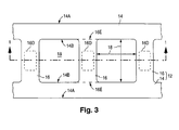
- Fig. 3 oriented the same as Fig. 2, illustrates the plan-view shape of one emitter electrode 12 more clearly.
- crosspieces 16 extend generally perpendicular to rails 14.
- Each rail 14 has an outer longitudinal edge 14A and an inner longitudinal edge 14B.
- Each crosspiece 16 has a pair of ends that merge seamlessly into rails 14 along inner edges 14B.
- Dashed lines 16E in Fig. 3 indicate the locations of the ends of one crosspiece 16.
- Emitter openings 18 are situated between crosspieces 16. As Fig. 3 indicates, emitter openings 18 are generally rectangular and extend in a straight line.
- the centerline-to-centerline spacing between the longitudinal centerlines (not shown) of emitter electrodes 12 is typically 270 - 300 ⁇ m.
- the width of each rail 14 is typically 30 ⁇ m.
- the dimension of each emitter opening 18 in the column direction is typically 150 - 170 ⁇ m.
- the width of each crosspiece 16 is typically 25 - 30 ⁇ m.
- the dimension of each emitter opening 18 in the row direction is typically 65 - 70 ⁇ m.
- Electrodes 12 typically consist of metal such as an alloy of nickel or aluminum. In this case, the thickness of electrodes 12 is typically 200 nm. Electrodes 12 can alternatively be formed with chromium, gold, silver, molybdenum or another corrosion-resistant metal of high electrical conductivity.
- a blanket electrically resistive layer 20 is situated on emitter electrodes 12. Resistive layer 20 extends down to baseplate 10 in emitter openings 18 and in the spaces between emitter electrodes 12. While the configuration of blanket layer 20 may seem to electrically intercouple different emitter electrodes 12, the resistance of such electrical intercoupling is so high that electrodes 12 are effectively electrically insulated from one another. Layer 20 provides a resistance of at least 10 6 ohms, typically 10 10 ohms, between each emitter electrode 12 and, as described below, each overlying electron-emissive element.
- Resistive layer 20 transmits a substantial percentage of the incident backside actinic radiation utilized in fabricating the electron-emitting device of Figs. 1 and 2.
- the backside radiation is UV light
- the percentage of UV light that passes directly through layer 20 is generally in the vicinity of 40 - 80%.
- layer 20 typically consists of cermet in which particles of a metal such as chromium are embedded in a transparent ceramic such as silicon oxide (silica).
- the thickness of layer 20 is typically 0.3 - 0.4 ⁇ m.
- a transparent dielectric layer 22 overlies resistive layer 20.
- Dielectric layer 22 typically consists of silicon oxide having a thickness of 0.1 - 0.2 ⁇ m.
- a group of laterally separated sets of electron-emissive elements 24 are situated in openings 26 extending through dielectric layer 22.
- Each set of electron-emissive elements 24 occupies an emission region that wholly overlies a designated region 16D of a corresponding one of crosspieces 16 in each emitter electrode 12.
- Each designated region 16D is largely row-direction centered on, and of lesser row-direction dimension than, its crosspiece 16. The same applies thus to the emission region for each set of electron-emissive elements 24. Since crosspieces 16 are separated by emitter openings 18, each designated region 16D is located between a consecutive pair of openings 18.
- Electron-emissive elements 24 can be shaped in various ways. In the example of Fig. 1, elements 24 are generally conical in shape. When elements 24 are configured as cones, elements 24 typically consist of molybdenum.
- a group of composite opaque laterally separated control electrodes 28 are situated on dielectric layer 22.
- Control electrodes 28 extend generally in the column direction and thus constitute column electrodes. Each control electrode 28 controls one column of sub-pixels. Three consecutive control electrodes 28 thus control one column of pixels.
- Control electrodes 28 cross over emitter electrodes 12 in a generally perpendicular manner. Each control electrode 28 overlies a corresponding one of crosspieces 16 in each emitter electrode 12. Electrodes 28 are symmetrically wider in the regions generally overlying crosspieces 16 than in the regions overlying portions of rails 14 so as to reduce the capacitance associated with electrodes 28.
- the centerline-to-centerline spacing between the longitudinal centerlines (not shown) of electrodes 28 is relatively constant along their lengths. As a whole, electrodes 28 thus extend generally parallel to one another.
- Each control electrode 28 consists of a main control portion 30 and a group of adjoining gate portions 32 equal in number to the number of emitter electrodes 12.
- Main control portions 30 extend fully across the field emitter in the column direction.
- Gate portions 32 are partially situated in large control openings 34 extending through main control portions 30 directly above designated regions 16D of crosspieces 16.
- Electron-emissive elements 24 are exposed through gate openings 36 in the segments of gate portions 32 situated in large control openings 34.
- Control openings 34 laterally bound (and therefore define) the emission regions for the laterally separated sets of electron-emissive elements 24. Hence, each control opening 34 is sometimes referred to as a "sweet spot”. Designated regions 16D are also defined by large control openings 34. Since three consecutive control electrodes 28 control one pixel column, the three sets of electron-emissive elements 24 in three consecutive large control openings 34 in a row of openings 34 form a pixel in the field emitter.
- Gate portions 32 partially overlie main control portions 30 in the example of Fig. 1.
- main control portions 30 can partially overlie gate portions 32.
- gate portions 32 are considerably thinner than main portions 30.
- the centerline-to-centerline spacing of control electrodes 28 between the longitudinal centerlines is typically 90 - 100 ⁇ m.
- the width of each control electrode 28 typically varies from a maximum of 70 - 80 ⁇ m over designated regions 16D to a minimum of 40 - 50 ⁇ m elsewhere.
- Main control portions 30 typically consist of chromium having a thickness of 0.2 ⁇ m.
- Gate portions 32 typically consist of chromium having a thickness of 0.04 ⁇ m.
- a focusing system 37 is situated on the parts of main control portions 30 and dielectric layer 22 not covered by control electrodes 28.
- focusing system 37 is formed with an electrically non-conductive base focusing structure 38 and a thin electrically non-insulating focus coating 39 situated over part of base focusing structure 38.
- focus coating 39 is thin and generally follows the lateral contour of base focusing structure 38, only the plan view of base structure 38 of focusing system 37 is illustrated in Fig. 2.
- Non-conductive base focusing structure 38 normally consists of electrically insulating material but can be formed with electrically resistive material of sufficiently high resistivity as to not cause control electrodes 28 to be electrically coupled to one another.
- Focus coating 39 normally consists of electrically conductive material, typically a metal such as aluminum having a thickness of 100 nm.
- the sheet resistance of focus coating 39 is typically 1 - 10 ohms/sq.
- focus coating 39 can be formed with electrically resistive material.
- the resistivity of focus coating 39 is normally considerably less than that of base focusing structure 38.
- Base focusing structure 38 has a group of openings 40, one for each different set of electron-emissive elements 24.
- focus openings 40 expose gate portions 32.
- Focus openings 40 are concentric with, and larger than, large control openings (sweet spots) 34.
- the greater dimensional compression in the column (vertical) direction than in the row (horizontal) direction causes focus openings 40 to appear longer in the row direction than in the column direction.
- the lateral dimension of openings 40 in the row direction is usually 50 - 150 ⁇ m, typically 80 - 90 ⁇ m.
- the lateral dimension of openings 40 in the column direction is usually 75 - 300 ⁇ m, typically 120 - 140 ⁇ m, and thus is normally significantly greater than the lateral dimension of openings 40 in the row direction.
- Focus coating 39 lies on the top surface of base focusing structure 38 and extends partway, typically in the vicinity of up to 50-75% of the way, into focus openings 40. Although non-conductive base focusing structure contacts control electrodes 28, non-insulating focus coating 39 is everywhere spaced apart from control electrodes 28. As viewed perpendicularly to the upper surface of baseplate 10, each different set of electron-emissive elements 24 is laterally surrounded by base focusing structure 38 and therefore by focus coating 39.
- Focusing system 37 primarily non-insulating focus coating 39, focuses electrons emitted from each different set of electron-emissive elements 24 so that the emitted electrons impinge on phosphor material in the corresponding light-emissive element of the light-emitting device situated opposite the electron-emitting device.
- focusing system 37 focuses electrons emitted from electron-emissive elements 24 in each sub-pixel so as to strike phosphor material in the same sub-pixel.
- Efficient performance of the electron focusing function requires that focus coating 39 extend considerably above elements 24 and that certain lateral distances from each set of elements 24 to certain parts of focusing system 37, specifically certain parts of coating 39, be controlled well.
- pixels are typically largely square with the three sub-pixels of each pixel being arranged in a line extending in the row direction. Portions of the active pixel area between rows of pixels are typically allocated for receiving edges of spacer walls.
- large control openings 34 are typically considerably closer together in the row direction than in the column direction. Better focus control is thus necessary in the row direction than in the column direction.
- the critical distances that need to be controlled to achieve good electron focusing are the row-direction distances from lateral edges of focusing system 37 to the nearest edges 34C of large control openings 34. Since edges 34C extend in the column direction, they are referred to here as column-direction edges.
- focusing system 37 also serves as a surface contacted by spacers, typically spacer walls, that enable the display to resist external forces such as air pressure while maintaining a desired spacing between the electron-emitting and light-emitting parts of the display.
- base focusing structure 38 as a tall main base portion 38M and a group of opposing pairs of critically aligned further base portions 38L.
- the two further base focusing portions 38L in each of the opposing pairs of further base portions 38L are situated on opposite sides of a corresponding one of large control openings 34 and thus on opposite sides of a corresponding one of the sets of electron-emissive elements 24.
- further base focusing portions 38L are slightly shorter than main base focusing portion 38M. Parts of focus coating 39 extend partway down the side surfaces of shorter focusing portions 38L into focus openings 40.
- each pair of opposing shorter base focusing portions 38L in focus openings 40 are situated at well-controlled row-direction distances from the corresponding set of electron-emissive elements 24.
- each pair of opposing shorter focusing portions 38L have lateral edges 38C vertically aligned to portions 28C of the outer lateral longitudinal edges 30 of the particular control electrode 28 that controls the corresponding set of electron-emissive elements 24.
- focusing-structure edges 38C extend in the column direction and are referred to here as column-direction edges.
- the row-direction distances from each pair of control-electrode longitudinal edge portions 28C, and therefore from the corresponding pair of focusing-structure column-direction edges 38C, to the column-direction edges 34C of large control opening 34 for the corresponding set of electron-emissive elements 24 are, as described below, determined by fixed photomask dimensions and are therefore well controlled. Since focus coating 39 extends partway down the sides of shorter focusing portions 38L into focus openings 40, the portions of focus coating 39 overlying each pair of opposing focusing portions 38L are spaced apart the corresponding set of electron-emissive elements 24 by well-controlled row-direction distances. Important in achieving these well-controlled row-direction spacings is the fact that control-electrode edge portions 28C, and thus focusing-structure column-direction edges 38C, overlie emitter openings 18.
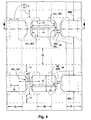
- Fig. 4 depicts two emitter electrodes 12. Item 42 in Fig. 4 indicates the area between each pair of consecutive electrodes 12.
- spacer walls are brought into contact with parts of focus coating 39 overlying main focusing portion 38M generally along some or all of areas 42. If desired, strips of main focusing portion 38M above spacer-contact areas 42 can be replaced with focusing material that extends to approximately the same height as shorter focusing portions 38L so as to provide grooves in base focusing portion 38, as covered there with focus coating 39, for receiving edges of the spacer walls.
- Base focusing structure 38 is normally created from negative-tone electrically insulating actinic material which is selectively exposed to actinic radiation and developed.
- the actinic material is preferably photo-polymerizable polyimide, typically Olin OCG7020 polyimide.
- Main focusing portion 38M typically extends 45 - 50 ⁇ m above dielectric layer 22. Further focusing portions 38L are normally 10 - 20% shorter than main portion 38M.
- a suitable potential is applied to focusing system 37, specifically to focus coating 39 to control the electron focusing.
- the focus control potential is of such a value, typically 25 - 50 volts relative to ground, so as to cause electrons emitted from each set of electron-emissive elements 24 to be focused on the corresponding (directly opposite) phosphor region in the light-emitting device.
- the field emitter of Figs. 1 - 4 is fabricated in the following manner.
- a blanket layer of the emitter-electrode material is deposited on baseplate 10 and patterned using a suitable photoresist mask to produce ladder-shaped emitter electrodes 12.
- Resistive layer 20 is then deposited on top of the structure.
- Dielectric layer 22 is deposited on top of resistive layer 20.
- a blanket layer of the electrically conductive material for main control portions 30 is deposited on layer 22 and patterned using a suitable photoresist mask to form main control portions 30, including large control openings 34.
- the photoresist mask is created by exposing a blanket layer of positive-tone photoresist to UV light selectively through a photomask (reticle) bearing a light-blocking pattern that corresponds to the desired pattern of main control portions 30.
- the row-direction distances from each pair of control-electrode longitudinal edge portions 28C to column-direction edges 34C of large control opening 34 for the corresponding set of electron-emissive elements 24 are established by fixed row-direction dimensions in this photomask. These photomask dimensions are largely the same for every control opening 34. As a result, the resulting row-direction distances from each pair of control-electrode edge portions 28C to column-direction edges 34C of the corresponding control opening 34 are well controlled.
- each control-opening sweet spot 34 is row-direction centered in its control electrode 28.
- the dimension of control openings 34 in the row direction is determined by the magnitude of the row direction distance across which electrons emitted by a set of electron-emissive elements 24 can be focused by focusing system 37 to strike the intended light-emissive element in the light emitting device. For instance, an electron emitted from an electron-emissive element 24 at the row-direction center of a focus opening 40 can readily be focused to strike the intended light-emissive element. On the other hand, an electron emitted from an electron-emissive element situated along either focusing-structure column-direction edge 38C of a focus opening 40 can generally not be regularly focused to strike the intended light-emissive element.
- control opening 34 being row-direction centered in its control electrode 28, the row-direction dimension of control openings 34 is generally in the range of 5 - 50% of the row-direction dimension of focus openings 40. More particularly, the control-opening row-direction dimension is 15 - 25%, typically 20%, of the focus-opening row-direction dimension.
- a blanket layer of the gate material is deposited on top of the structure and patterned using another photoresist mask to form gate portions 32. If gate portions 32 are to underlie segments of main control portions 30 rather than overlie segments of main control portions 30, the last two deposition/patterning operations are reversed.
- base focusing structure 38 is normally created by a process involving (a) backside exposure of actinic material to actinic radiation using emitter electrodes 12 and control electrodes 28 as a radiation-blocking mask, (b) frontside exposure of the actinic material through a suitable photomask, and (c) removal of the unexposed actinic material in a development operation.
- gate openings 36 and dielectric openings 26 are created respectively in gate portions 32 and dielectric layer 22 according to a charged-particle tracking procedure of the type described in U.S. Patent 5, 559, 389 or 5, 564, 959.
- Electron-emissive elements 24 are created as cones by depositing electrically conductive material through gate openings 36 and into dielectric openings 26 according to a deposition technique of the type described in either of these patents.
- Base focusing structure 38 is now formed as illustrated in Figs. 5a - 5d.
- a primary blanket layer 38P of negative-tone electrically insulating actinic material is provided on top of the structure to a thickness sufficient to produce main base focusing portion 38M.
- the electron-emitting structure is subjected to backside actinic radiation 46 that impinges perpendicularly on the lower (exterior) surface of faceplate 10 as shown in Fig. 5b.
- Baseplate 10 is largely transmissive of backside radiation 46. Accordingly, radiation passes through baseplate 10 traveling from its lower surface to its upper (interior) surface.
- Electrodes 12 and 28 are largely non-transmissive of backside radiation 46.
- Resistive layer 20 directly transmits a substantial percentage of radiation 46, typically in the vicinity of 40 - 80% of radiation 46 as mentioned earlier.
- Dielectric layer 22 largely transmits radiation 46.
- the portion 38Q of primary actinic layer 38P not shadowed by a radiation-blocking mask formed with electrodes 12 and 28 is exposed to radiation 46 and changes chemical structure.
- backside radiation 46 passes through openings 18 in emitter electrodes 12. Segments of control electrodes 28, specifically segments of main control portions 30, extending up to portions 28C of the longitudinal edges of electrodes 28 overlie emitter openings 18. As a result, sections of primary layer 38P vertically aligned with lateral control-electrode edges 28C are exposed to radiation 46 to define column-direction lateral edges 38C of base focusing structure 38.
- Photomask 47 has radiation-blocking areas 47B at regions above focus openings 40. Radiation-blocking areas 47B are slightly larger than openings 40 in the row direction. Each of blocking areas 47B corresponds to the region indicated by horizontal arrow 44 and vertical arrow 40 in Fig. 2 or 4. Material of primary layer 46 not shadowed by blocking areas 47B is exposed to frontside radiation 48 and changes chemical structure.
- the backside exposure can be performed after the frontside exposure.
- the actinic material is photo-polymerizable polyimide, such as Olin OCG7020 polyimide
- the actinic radiation during both the backside and frontside exposures is typically UV light.
- the polyimide changes chemical structure by undergoing polymerization.
- a development operation is performed to remove the unexposed portions of primary layer 38P, thereby producing base focusing structure 38 as shown in Fig. 5d. Due to the presence of baseplate 10, backside radiation 46 normally did not fully penetrate primary layer 38P at the backside exposed areas. Since further base focusing portions 38L were only exposed to backside radiation 46, further focusing portions 38L are normally shorter than main focusing portion 38M. If backside radiation 46 fully penetrates primary actinic layer 46P, the height differential between focusing portions 38M and 38L is reduced or, with sufficient backside exposure, eliminated.
- Focus coating 39 is formed over base focusing structure 38, typically by performing a suitably angled evaporation of the focus-coating material.
- focusing system 37 is provided with one or more electrical conductors (not shown) which contact focus coating-39 and through focusing system 37 is externally accessed for providing the focus control potential to focus coating 39.
- the access conductor or conductors are typically configured and fabricated as described in Haven et al, cited in the previous paragraph. This completes the formation of focusing system 37, thereby yielding the field-emitter of Figs. 1 and 2.
- the field emitter is sealed to the light-emitting device through an outer wall.
- the sealing operation typically entails mounting the outer wall and the spacer walls on the light-emitting device.
- This composite assembly is then brought into contact with the field emitter and hermetically sealed in such a manner that the internal display pressure is typically 1,3 33 x 10 -10 - 1,333 x 10 -9 bar (10 -7 - 10 -6 torr).
- the spacer walls contact focusing system 37 along part or all of areas 42 in Fig. 4.
- An alternative way of processing negative-tone primary actinic layer 38P to produce a base focusing structure similar to base structure 38 involves first exposing primary layer 38P to frontside actinic radiation 48 through a photomask having radiation-blocking stripes that extend in the row direction fully across the display's intended active area. Each row-direction radiation-blocking stripe overlies the intended locations for (a) a row of focus openings 40 and (b) the intervening generally rectangular primary actinic strips situated between the intended locations for focus openings 40 in that row. These rectangular primary actinic strips extend longitudinally in the column direction. Frontside radiation 48 fully penetrates layer 38P at the exposed areas, causing the so-exposed actinic material below the row-direction radiation-blocking stripes to change chemical structure.
- the exposure with backside radiation 46 is now performed so that radiation 46 partially penetrates primary layer 38P at the exposed areas.
- the only unexposed primary actinic material subjected to radiation 46 (and thus not shadowed by the mask formed with electrodes 12 and 28) consists of the rectangular column-direction primary actinic strips situated between the intended locations for focus openings 40 in each focus opening row. Consequently, the exposed material of primary layer 38P has column-direction edges vertically aligned to portions of control-electrode column-direction edges 28C generally at the locations for column-direction focus edges 38C in Figs. 1 and 2.
- Primary layer 38P is now developed to remove the unexposed actinic material.
- the exposed remainder of layer 38P forms the base focusing structure.
- backside radiation 46 only partially penetrated primary layer 38P at the backside-exposed areas, the height of the full widths of the column-direction rectangular focusing strips between focus openings 40 is both largely uniform and less than the height of the remainder of the base focusing structure.
- focus openings 40 here are, in plan view, more rectangular than focus openings 40 in Fig. 2, the shape of the base focusing structure is generally the same as that shown for base structure 38 in Figs. 1 and 2.
- the backside exposure in this alternative process can be performed under such conditions that backside radiation 46 fully penetrates primary actinic layer 38P at the exposed areas.
- the height differential between (a) the column-direction rectangular focusing strips situated between focus openings 40 in each focus opening row and (b) the remainder of the base focusing structure is then reduced-or eliminated.
- the base focusing structure is provided with an electrically non-insulating focus coating analogous to focus coating 39 to form a composite focusing structure similar to focusing system 37.
- the focus coating typically consists of electrical conductive material evaporatively deposited in the manner described above for focus coating 39.
- the resultant non claimed field emitter appears generally as shown in Figs. 1 and 2 subject to the above-mentioned focusing structure differences.
- a base focusing structure similar to base structure 38 can be formed from non-actinic electrically non-conductive material using positive-tone actinic material, typically photoresist, combined with a lift-off step to achieve self-alignment to control-electrode edge portions 28C.
- the process described above for creating base structure 38 is modified by providing a primary blanket layer of positive-tone photoresist on top of the partially finished field emitter directly after removing the portion of the blanket layer of emitter cone material at the desired location for base structure 38.
- Emitter electrodes 12 and control electrodes 28 form a mask that prevents the directly overlying portions of the blanket photoresist layer from being exposed to backside radiation 46.
- the exposed portion of the primary photoresist layer changes chemical structure.
- Radiation 46 and radiation 48 are both normally UV light. Either radiation exposure can be done first.
- a development operation is conducted on the primary photoresist layer. Because the photoresist is positive-tone actinic material, the exposed material of the photoresist layer is removed during the development operation.
- the remaining photoresist consists of portions having substantially the reverse configuration of base focusing structure 38 in Figs. 1 and 2. Due to the backside exposure, sections of the remaining photoresist have lateral edges vertically aligned with control-electrode edge portions 28C.
- a blanket layer of non-actinic electrically non-conductive material is formed on top of the structure.
- the remaining portions of the primary photoresist layer are removed so as to lift off the overlying portions of the blanket non-actinic non-conductive layer.
- the remainder of the non-actinic non-conductive layer forms a base focusing structure configured substantially the same as base focusing structure 38 except that the height difference between main portion 38M and shorter portions 38L is not present.
- the base focusing structure created from the non-actinic non-conductive material has pairs of opposing lateral column-direction edges vertically aligned with control-electrode edge portions 28C. Consequently, the row-direction spacings from each of these pairs of focusing-structure column-direction edges to column-direction edges 34C of the corresponding control-opening sweet spot 34 are well controlled.
- An electrically non-insulating focus coating is formed on the base focusing structure to create a composite focusing structure analogous to focusing system 37.
- the non-conductive base focus structure has a considerably higher resistivity than the non-insulating focus coating.
- the resulting nonclaimed field emitter appears generally as shown in Figs. 1 and 2 except that the composite focusing structure is of largely uniform height.
- a variation of the foregoing process employs positive-tone actinic material in creating another focusing system similar to focusing system 37 except that largely the entire focusing system consists of electrically non-insulating material, typically electrically conductive material, spaced apart from control electrodes 28. Since the focusing system is typically electrically conductive, there is no need to provide a separate electrically non-insulating focus coating corresponding to focus coating 39.
- This variation begins with the structure existent after the portion of the blanket layer of emitter conductive material has been removed at the desired location for base focusing structure 38 so that portions of control electrodes 28 are uncovered.
- a layer of electrically non-conductive material, typically an electrical insulator, transmissive of backside radiation 46 is provided on at least the uncovered sections of the lateral edges of control electrodes 28.
- the non-conductive layer is normally a blanket layer that fully covers the previously uncovered portions of electrodes 28 and the portions of dielectric layer 22 between those portions of electrodes 28.
- a primary blanket layer of positive-tone photoresist is provided on top of the non-conductive layer. The blanket photoresist layer lies on any material of electrodes 28 and/or dielectric layer 22 not covered by the non-conductive layer.
- Electrodes 12 and 28 again form a mask that shields the overlying portions of the positive-tone photoresist from backside radiation 46. Since the non-conductive layer is transmissive of radiation 46, exposed photoresist of changed chemical structure is produced in largely the same pattern as in the foregoing process that employs positive-tone photoresist at this point.
- the primary photoresist layer is developed to remove the exposed photoresist material. Sections of the remaining photoresist thus have lateral edges vertically aligned to the outside sections of the surfaces of the non-conductive material covering the sections of the lateral edges of control electrodes 28.
- the remaining portions of the primary photoresist layer are removed so as to lift off the overlying portions of the blanket non-insulating layer.
- the remainder of the blanket non-insulating layer forms an electrically non-insulating focusing structure of substantially the same configuration as base focusing structure 38 except that the height differential between portions 38M and 38L is again eliminated.
- the non-insulating focusing structure has pairs of opposing lateral column-direction edges vertically aligned to the outside surface sections of the non-conductive material covering the lateral edge sections of control electrodes 28. Accordingly, the pairs of opposing lateral column-direction edges of the focusing structure are self-aligned to control-electrode edge portions 28C.
- the row-direction spacings from each of these pairs of focusing-structure column-direction edges to column-direction edges 34C of the corresponding sweet spot 34 are again well controlled.
- the non-insulating focusing structure forms an electron focusing system separated from control electrodes 28 by sections of non-conductive material and/or open spaces. To the extent that any of the non-conductive material separates the focusing system from electrodes 28, the resistivity of the non-conductive material is sufficiently high that the focusing system is effectively electrically insulated from electrodes 28.
- Another variation of the foregoing process that employs positive-tone active actinic material in creating a focusing system consisting largely of electrically non-insulating material begins with the structure existing after the non-conductive layer is provided on at least the lateral edges of control electrodes 28.
- a thin blanket seed metal layer is deposited on top of the structure. If any of the seed metal layer contacts control electrodes 28, the seed metal is normally selectively etchable with respect to the control-electrode material.
- the seed layer is of such characteristics as to largely transmit backside actinic radiation 46.
- a primary blanket layer of positive-tone photoresist is provided on top of the seed metal layer.
- the exposures with radiation 46 and 48 are performed. Electrodes 12 and 28 form a mask that prevents the directly overlying photoresist from being exposed to backside radiation 46. Since the seed layer transmits radiation 46, the exposed photoresist of changed chemical structure has largely the same pattern as in the two foregoing process variations.
- the exposed photoresist portions are removed in a development step. Accordingly, sections of the remaining photoresist again have lateral edges vertically aligned to the outside surface sections of the non-conductive material covering the lateral edge sections of control electrodes 28. Also, a pattern of the seed metal layer is now exposed at the location of removed photoresist.
- a focus structure metal is electrochemically deposited (electroplated) into the patterned opening in the remaining photoresist, using the exposed seed metal to initiate the electrochemical deposition.
- the deposition is terminated before the focus structure metal reaches the top of the photoresist.
- the remaining photoresist is removed after which the exposed seed metal is removed.
- the remainder of the focus structure metal forms an electrically non-insulating focusing structure, specifically an electrically conductive focusing structure, configured substantially the same as in the immediately previous process variation. Pairs of opposing lateral column-direction edges of the metal focusing structure are thus self-aligned to control-electrode edge portions 28C.
- the electron focusing system formed with the metal focusing structure is separated from control electrodes 28 by open spaces and/or sections of non-conductive material.
- the resistivity of any non-conductive material separating electrodes 28 from the focusing system is sufficiently high that the focusing system is effectively electrically insulated from electrodes 28.
- the frontside exposure can be deleted in fabricating the electron-emitting device of the invention, especially when base focusing structure 38 is not utilized to contact spacers such as spacer walls through conductive focus coating 39.
- multiple frontside exposures can be performed on the actinic material utilized to make base structure 38, each frontside exposure normally being performed through a different photomask.
- multiple backside exposures can be performed on the actinic material employed to create structure 38. In this case, each additional backside exposure is performed through a photomask, different photomasks normally being employed when there are two or more additional backside exposures.
- Additional radiation-blocking features can be provided over dielectric layer 20 for use in combination with, or as substitutes for, control electrodes 28 in blocking part of the backside actinic radiation that passes through emitter openings 18 or 74 during the formation of base focusing structure 38.
- Multiple layers of actinic material can be utilized in forming base structure 38.
- the backside exposure through the area not shadowed by control electrodes 28 and emitter electrodes 12 or 70 can be employed in forming a self-aligned structure other than a focusing structure.
- the above-mentioned variations involving eliminating the frontside exposure, employing multiple frontside exposures and/or multiple backside exposures, and utilizing multiple layers of actinic material are especially applicable to the formation of such other structures.
- additional features can be provided above emitter electrodes 12 or 70 for use in combination with, or substitutes for, control electrodes 28 in blocking part of the backside actinic radiation that passes through emitter openings 18 or 74.
- Each opaque emitter electrode 12 or 70 can be part of a composite emitter electrode that includes one or more transparent electrically conductive portions situated above or below electrode 12 or 70.
- the transparent emitter electrode material extends at least partially across, typically fully across, at least part of, typically all, of emitter openings 18 or 74.
- the transparent emitter electrode material is largely transmissive of backside actinic radiation 46.
- - Indium-tin oxide is an example of an electrical conductor suitable for the transparent conductive material in such a composite emitter electrode.
- Each emitter electrode 12 or 70 can have three or more rails 14, provided that crosspieces 16 are present between at least two of rails 14. When crosspieces 16 are located between each consecutive pair of all of three or more of rails 14, emitter electrodes 12 or 70 essentially become grids. Backside radiation 46 then passes through the grid openings, exemplified by emitter openings 18 in the ladder shape described above for electrodes 12 or 70.
- Grid-shaped versions of opaque emitter electrodes 12 or 70 can be combined with electrically conductive transparent material, such as indium-tin oxide, to form composite emitter electrodes. This enables the composite electrodes to have greater electrical conductivity than that typically provided by indium-tin oxide.
- the actinic radiation can consist of or include light other than UV light.
- One example is IR light.
- the actinic radiation can consist of or include radiation other than light.
- Different types of actinic radiation can be employed in different radiation-exposure steps.
- the chemical structure of the exposed portions of primary actinic layer 38P can be changed by selectively exposing layer 38P to a directed energy beam, such as a laser, rather than exposing layer 38P through photomask 47.
- the actinic material exposed to actinic radiation can change chemical structure by phenomena other than polymerization. This occurs especially when the actinic material is positive tone, the exposed actinic material being removed during the development step. With positive-tone actinic material, the exposed material is typically converted into an acid that can be removed with an aqueous base developer. With positive-tone actinic material, certain lateral edges of the unexposed actinic material remaining after the development step are vertically aligned to parts or all of the longitudinal edges of control electrodes 28 in a manner complementary to that described above.
- primary actinic layer 38P can be thermosetting polymeric material, typically a thermosetting plastic, while backside radiation 46 consists of IR light.
- backside radiation 46 consists of IR light.
- the exposed portions of primary layer 38P harden.
- a laser can be scanned selectively over layer 46P to perform the frontside exposure.
- Each of the sets of electron-emissive elements 24 can consist of only one element 24 rather than multiple elements 24. Multiple electron-emissive elements can be situated in one opening through dielectric layer 22. Electron-emissive elements 24 can have shapes other than cones. One example is filaments, while another is randomly shaped particles such as diamond grit.
Description
- This invention relates to electron-emitting devices. More particularly, this invention relates to the structure and fabrication, including testing, of an electron-emitting device suitable for use in a flat-panel display of the cathode-ray tube ("CRT") type.
- A flat-panel CRT display basically consists of an electron-emitting device and a light-emitting device that operate at low internal pressure. The electron-emitting device, commonly referred to as a cathode, contains electron-emissive elements that emit electrons over a wide area. The emitted electrons are directed towards light-emissive elements distributed over a corresponding area in the light-emitting device. Upon being struck by the electrons, the light-emissive elements emit light that produces an image on the viewing surface of the display.
- Specifically, the electron-emissive elements are conventionally situated over generally parallel emitter electrodes that are opaque--i.e., impervious to light, typically ultraviolet ("UV") and infrared ("IR") light as well as visible light. In an electron-emitting device that operates according to field-emission principles, control electrodes typically cross over, and are electrically insulated from, the emitter electrodes. A set of electron-emissive elements are electrically coupled to each emitter electrode where it is crossed by one of the control electrodes. The electron-emissive elements are exposed through openings in the control electrodes. When a suitable voltage is applied between a control electrode and an emitter electrode, the control electrode extracts electrons from the associated electron-emissive elements. An anode in the light-emitting device attracts the electrons to the light-emissive elements.
- The electron-emitting device in a flat-panel CRT display commonly contains a focusing structure that helps control the trajectories of the electrons so that they largely only strike the intended light-emissive elements. The focusing structure normally extends above the control electrodes. The lateral relationship of the focusing structure to the sets of electron-emissive elements is critical to achieving high display performance. In fabricating the electron-emitting device, the opaque nature of the emitter electrodes can present an impediment to achieving the requisite lateral spacing between the focusing structure and the sets of electron-emissive elements. Accordingly, it would be desirable to configure the emitter electrodes in such as way as to facilitate controlling the lateral positions of components, such as the focusing structure, in the electron-emitting device.
- Short circuits sometime occur between the control electrodes, on one hand, and the emitter electrodes, on the other hand. The presence of a short circuit can have a very detrimental effect on the display's performance. For example, a short circuit at the crossing between a particular control electrode and a particular emitter electrode can prevent part or all of the set of electron-emissive elements associated with those two electrodes from operating properly. It would also be desirable to have a way for configuring the emitter electrodes to facilitate removal of short-circuit defects.
- In the present invention, an emitter electrode for an electron-emitting device is formed such that during fabrication of the electron-emitting device, the emitter openings can be utilized in a manner that permits features, such as a focusing system, to be self-aligned to other features, such as control electrodes, so as to achieve desired lateral spacings in the device.
- When at least part of the focusing system is created from actinic material, portions of the control electrodes typically overlie the emitter openings in the ladder-shaped emitter electrode. The actinic material is selectively exposed to backside actinic radiation that passes through the emitter openings. During the backside exposure, the portions of the control electrodes overlying the emitter openings serve as part of a radiation-blocking mask that results in edges of the focusing system being self-aligned to parts of the edges of the control electrodes. Similar self-alignment is achieved in creating other structures from actinic material using the control electrodes or other such features extending over the emitter openings as part of a mask for blocking backside actinic radiation that passes through the emitter openings.
- In short, the invention overcomes fabrication difficulties arising from the fact that the material of the emitter electrode is normally opaque and thus largely non-transmissive of actinic radiation. The openings in the present emitter electrode permit certain edges in the electron-emitting device to be self-aligned to other edges, thereby enabling certain critical spacings in the device to be well controlled. Device performance is improved.
-
- Fig. 1 is a cross-sectional side view of a portion of a electron-emitting device configured so as to have emitter electrodes in the general shape of ladders.
- Fig. 2 is a plan view of the portion of the electron-emitting device in Fig. 1. -
- Fig. 3 is a plan view of the emitter electrode in the portion of the electron-emitting device in Fig. 1.
- Fig. 4 is a plan view of the base focusing structure, column electrodes, and two emitter electrodes in the electron-emitting device of Fig. 1.
- Figs. 5a - 5d are cross-sectional side views representing steps that employ the invention's teachings in manufacturing the base focusing structure of the electron-emitting device in Figs. 1, 2, and 4.
- The cross section of Fig. 1 is taken through plane 1-1 in each of Figs. 2 - 4.
- Like reference symbols are employed in the drawings and in the description of the preferred embodiments to represent the same, or very similar, item or items.
- The present writing describes, as an unclaimed example, matrix-addressed gated electron-emitting device having a layer of emitter electrodes which, in plan view, are shaped generally like ladders. With respect to the emitter electrodes, "plan view" means as viewed in a direction generally perpendicular to the emitter-electrode layer. The electron emitter typically operates according to field-emission principles in producing electrons that cause visible light to be emitted from corresponding light-emissive phosphor elements of a light-emitting device. The combination of the electron-emitting and light-emitting devices forms a cathode-ray tube of a flat-panel display such as a flat-panel television or a flat-panel video monitor for a personal computer, a lap-top computer, or a workstation.
- In accordance with the presently claimed invention, in fabricating the present electron emitter, actinic material is typically created in a desired shape by a procedure that involves exposing part of the material to backside actinic radiation that passes through the openings between the crosspieces of the ladder-shaped emitter electrodes. A layer of material is "actinic" when the layer can be patterned by exposing the layer to radiation that causes the exposed material to change chemical structure and then developing the layer to remove either the exposed material or the unexposed material. The present invention normally employs negative-tone actinic material in which the material remaining after the development step is the exposed material, the chemical structure of the exposed material typically having changed by undergoing polymerization. Radiation, typically UV light, is referred to as "actinic" to indicate that the radiation causes the changes in chemical structure of the material exposed to the radiation.
- In the following description, the term "electrically insulating" (or "dielectric") generally applies to materials having a resistivity greater than 1010 ohm-cm. The term "electrically non-insulating" thus refers to materials having a resistivity below 1010 ohm-cm. Electrically non-insulating materials are divided into (a) electrically conductive materials for which the resistivity is less than 1 ohm-cm and (b) electrically resistive materials for which the resistivity is in the range of 1 ohm-cm to 1010 ohm-cm. These categories are determined at an electric field of no more than 1 volt/µm. Similarly, the term "electrically non-conductive" refers to materials having a resistivity of at least 1 ohm-cm, and includes electrically resistive and electrically insulating materials.
- Examples of electrically conductive materials (or electrical conductors) are metals, metal-semiconductor compounds (such as metal silicides), and metal-semiconductor eutectics. Electrically conductive materials also include semiconductors doped (n-type or p-type) to a moderate or high level. Electrically resistive materials include intrinsic and lightly doped (n-type or p-type) semiconductors. Further examples of electrically resistive materials are (a) metal-insulator composites, such as cermet (ceramic with embedded metal particles), (b) forms of carbon such as graphite, amorphous carbon, and modified (e.g., doped or laser-modified) diamond, (c) and certain silicon-carbon compounds such as silicon-carbon nitrogen.
- Referring to the drawings, Fig. 1 illustrates by way of example a side cross section of part of a nonclaimed matrix-addressed gated electron-emitting device The device in Fig. 1 operates in field-emission mode and is often referred to here as a field emitter. Fig. 2 depicts a plan view of the part of the field emitter shown in Fig. 1. To simplify pictorial illustration, dimensions in the vertical direction in Fig. 2 are illustrated at a compressed scale compared to dimensions in the horizontal direction.
- The field emitter of Figs. 1 and 2 is employed in a color flat-panel CRT display divided into rows and columns of color picture elements ("pixels"). The row direction--i.e., the direction along the rows of pixels--is the horizontal direction in Figs. 1 and 2. The column direction, which extends perpendicular to the row direction and thus along the columns of pixels, extends perpendicular to the plane of Fig. 1. The column direction extends vertically in Fig. 2. Each color pixel contains three sub-pixels, one for red, another for green, and the third for blue.
- The field emitter of Figs. 1 and 2 is created from a thin transparent
flat baseplate 10. Typically,baseplate 10 consists of glass such as Schott D263 glass having a thickness of approximately 1 mm. - A group of opaque parallel laterally separated ladder-shaped
emitter electrodes 12 are situated onbaseplate 10.Emitter electrodes 12 extend in the row direction and thus constitute row electrodes. Eachemitter electrode 12 consists of a pair of parallel equal-widthstraight rails 14 and a group of parallel equal-widthstraight crosspieces 16. The cross section of Fig. 1 is taken through a plane at which only crosspieces 16 are visible. Fig. 2 illustrates, in dashed line, rails 14 andcrosspieces 16 of oneemitter electrode 12. - Fig. 3, oriented the same as Fig. 2, illustrates the plan-view shape of one
emitter electrode 12 more clearly. As shown in Fig. 3,crosspieces 16 extend generally perpendicular to rails 14. Eachrail 14 has an outerlongitudinal edge 14A and an innerlongitudinal edge 14B. Eachcrosspiece 16 has a pair of ends that merge seamlessly intorails 14 alonginner edges 14B. Dashedlines 16E in Fig. 3 indicate the locations of the ends of onecrosspiece 16.Emitter openings 18 are situated betweencrosspieces 16. As Fig. 3 indicates,emitter openings 18 are generally rectangular and extend in a straight line. - The centerline-to-centerline spacing between the longitudinal centerlines (not shown) of
emitter electrodes 12 is typically 270 - 300 µm. The overall width of eachemitter electrode 12--i.e., the distance betweenouter rail edges 14A--is typically 210 - 230 µm. The width of eachrail 14 is typically 30 µm. Accordingly, the dimension of each emitter opening 18 in the column direction is typically 150 - 170 µm. The width of each crosspiece 16 is typically 25 - 30 µm. The dimension of each emitter opening 18 in the row direction is typically 65 - 70 µm. -
Rails 14 andcrosspieces 16 ofemitter electrodes 12 are typically of approximately the same thickness.Electrodes 12 typically consist of metal such as an alloy of nickel or aluminum. In this case, the thickness ofelectrodes 12 is typically 200 nm.Electrodes 12 can alternatively be formed with chromium, gold, silver, molybdenum or another corrosion-resistant metal of high electrical conductivity. - A blanket electrically
resistive layer 20 is situated onemitter electrodes 12.Resistive layer 20 extends down tobaseplate 10 inemitter openings 18 and in the spaces betweenemitter electrodes 12. While the configuration ofblanket layer 20 may seem to electrically intercoupledifferent emitter electrodes 12, the resistance of such electrical intercoupling is so high thatelectrodes 12 are effectively electrically insulated from one another.Layer 20 provides a resistance of at least 106 ohms, typically 1010 ohms, between eachemitter electrode 12 and, as described below, each overlying electron-emissive element. -
Resistive layer 20 transmits a substantial percentage of the incident backside actinic radiation utilized in fabricating the electron-emitting device of Figs. 1 and 2. When the backside radiation is UV light, the percentage of UV light that passes directly through layer 20 (i.e., without significant scattering) is generally in the vicinity of 40 - 80%. For this purpose,layer 20 typically consists of cermet in which particles of a metal such as chromium are embedded in a transparent ceramic such as silicon oxide (silica). The thickness oflayer 20 is typically 0.3 - 0.4 µm. - A
transparent dielectric layer 22 overliesresistive layer 20.Dielectric layer 22 typically consists of silicon oxide having a thickness of 0.1 - 0.2 µm. - A group of laterally separated sets of electron-
emissive elements 24 are situated inopenings 26 extending throughdielectric layer 22. Each set of electron-emissive elements 24 occupies an emission region that wholly overlies a designatedregion 16D of a corresponding one ofcrosspieces 16 in eachemitter electrode 12. Each designatedregion 16D is largely row-direction centered on, and of lesser row-direction dimension than, itscrosspiece 16. The same applies thus to the emission region for each set of electron-emissive elements 24. Sincecrosspieces 16 are separated byemitter openings 18, each designatedregion 16D is located between a consecutive pair ofopenings 18. - The particular electron-
emissive elements 24 overlying eachemitter electrode 12 are electrically coupled to thatelectrode 12 throughresistive layer 20. Electron-emissive elements 24 can be shaped in various ways. In the example of Fig. 1,elements 24 are generally conical in shape. Whenelements 24 are configured as cones,elements 24 typically consist of molybdenum. - A group of composite opaque laterally separated
control electrodes 28 are situated ondielectric layer 22.Control electrodes 28 extend generally in the column direction and thus constitute column electrodes. Eachcontrol electrode 28 controls one column of sub-pixels. Threeconsecutive control electrodes 28 thus control one column of pixels. -
Control electrodes 28 cross overemitter electrodes 12 in a generally perpendicular manner. Eachcontrol electrode 28 overlies a corresponding one ofcrosspieces 16 in eachemitter electrode 12.Electrodes 28 are symmetrically wider in the regions generally overlyingcrosspieces 16 than in the regions overlying portions ofrails 14 so as to reduce the capacitance associated withelectrodes 28. The centerline-to-centerline spacing between the longitudinal centerlines (not shown) ofelectrodes 28 is relatively constant along their lengths. As a whole,electrodes 28 thus extend generally parallel to one another. - Each
control electrode 28 consists of amain control portion 30 and a group of adjoininggate portions 32 equal in number to the number ofemitter electrodes 12.Main control portions 30 extend fully across the field emitter in the column direction.Gate portions 32 are partially situated inlarge control openings 34 extending throughmain control portions 30 directly above designatedregions 16D ofcrosspieces 16. Electron-emissive elements 24 are exposed throughgate openings 36 in the segments ofgate portions 32 situated inlarge control openings 34. -
Control openings 34 laterally bound (and therefore define) the emission regions for the laterally separated sets of electron-emissive elements 24. Hence, each control opening 34 is sometimes referred to as a "sweet spot". Designatedregions 16D are also defined bylarge control openings 34. Since threeconsecutive control electrodes 28 control one pixel column, the three sets of electron-emissive elements 24 in three consecutivelarge control openings 34 in a row ofopenings 34 form a pixel in the field emitter. -
Gate portions 32 partially overliemain control portions 30 in the example of Fig. 1. Alternatively,main control portions 30 can partially overliegate portions 32. In either case,gate portions 32 are considerably thinner thanmain portions 30. - The centerline-to-centerline spacing of
control electrodes 28 between the longitudinal centerlines (again, not shown) is typically 90 - 100 µm. The width of eachcontrol electrode 28 typically varies from a maximum of 70 - 80 µm over designatedregions 16D to a minimum of 40 - 50 µm elsewhere.Main control portions 30 typically consist of chromium having a thickness of 0.2 µm.Gate portions 32 typically consist of chromium having a thickness of 0.04 µm. - A focusing
system 37, generally arranged in a waffle-like pattern as viewed perpendicularly to the upper (interior) surface offaceplate 10, is situated on the parts ofmain control portions 30 anddielectric layer 22 not covered bycontrol electrodes 28. Referring to Fig. 1, focusingsystem 37 is formed with an electrically non-conductivebase focusing structure 38 and a thin electricallynon-insulating focus coating 39 situated over part ofbase focusing structure 38. Inasmuch as focuscoating 39 is thin and generally follows the lateral contour ofbase focusing structure 38, only the plan view ofbase structure 38 of focusingsystem 37 is illustrated in Fig. 2. - Non-conductive
base focusing structure 38 normally consists of electrically insulating material but can be formed with electrically resistive material of sufficiently high resistivity as to not causecontrol electrodes 28 to be electrically coupled to one another.Focus coating 39 normally consists of electrically conductive material, typically a metal such as aluminum having a thickness of 100 nm. The sheet resistance offocus coating 39 is typically 1 - 10 ohms/sq. In certain applications, focus coating 39 can be formed with electrically resistive material. In any event, the resistivity offocus coating 39 is normally considerably less than that ofbase focusing structure 38. -
Base focusing structure 38 has a group ofopenings 40, one for each different set of electron-emissive elements 24. In particular,focus openings 40expose gate portions 32.Focus openings 40 are concentric with, and larger than, large control openings (sweet spots) 34. - In Fig. 2, the greater dimensional compression in the column (vertical) direction than in the row (horizontal) direction causes
focus openings 40 to appear longer in the row direction than in the column direction. Actually, the opposite case normally arises. The lateral dimension ofopenings 40 in the row direction is usually 50 - 150 µm, typically 80 - 90 µm. The lateral dimension ofopenings 40 in the column direction is usually 75 - 300 µm, typically 120 - 140 µm, and thus is normally significantly greater than the lateral dimension ofopenings 40 in the row direction. -
Focus coating 39 lies on the top surface ofbase focusing structure 38 and extends partway, typically in the vicinity of up to 50-75% of the way, intofocus openings 40. Although non-conductive base focusing structure contacts controlelectrodes 28,non-insulating focus coating 39 is everywhere spaced apart fromcontrol electrodes 28. As viewed perpendicularly to the upper surface ofbaseplate 10, each different set of electron-emissive elements 24 is laterally surrounded bybase focusing structure 38 and therefore byfocus coating 39. - Focusing
system 37, primarilynon-insulating focus coating 39, focuses electrons emitted from each different set of electron-emissive elements 24 so that the emitted electrons impinge on phosphor material in the corresponding light-emissive element of the light-emitting device situated opposite the electron-emitting device. In other words, focusingsystem 37 focuses electrons emitted from electron-emissive elements 24 in each sub-pixel so as to strike phosphor material in the same sub-pixel. Efficient performance of the electron focusing function requires thatfocus coating 39 extend considerably aboveelements 24 and that certain lateral distances from each set ofelements 24 to certain parts of focusingsystem 37, specifically certain parts ofcoating 39, be controlled well. - More particularly, pixels are typically largely square with the three sub-pixels of each pixel being arranged in a line extending in the row direction. Portions of the active pixel area between rows of pixels are typically allocated for receiving edges of spacer walls. The net result of this configuration is that
large control openings 34 are typically considerably closer together in the row direction than in the column direction. Better focus control is thus necessary in the row direction than in the column direction. Accordingly, the critical distances that need to be controlled to achieve good electron focusing are the row-direction distances from lateral edges of focusingsystem 37 to thenearest edges 34C oflarge control openings 34. Sinceedges 34C extend in the column direction, they are referred to here as column-direction edges. - The internal pressure in the final fla-panel display that contains the field emitter of Figs. 1 and 2 is very low, generally in the vicinity of 1.33 x 10⁻⁵ - 1.33x10⁻⁴ Pa (10-7 - 10-6 torr), With
baseplate 10 being thin, focusingsystem 37 also serves as a surface contacted by spacers, typically spacer walls, that enable the display to resist external forces such as air pressure while maintaining a desired spacing between the electron-emitting and light-emitting parts of the display. - The preceding distance and spacer-contact considerations are addressed by configuring
base focusing structure 38 as a tallmain base portion 38M and a group of opposing pairs of critically alignedfurther base portions 38L. The two furtherbase focusing portions 38L in each of the opposing pairs offurther base portions 38L are situated on opposite sides of a corresponding one oflarge control openings 34 and thus on opposite sides of a corresponding one of the sets of electron-emissive elements 24. As shown in Fig. 1, furtherbase focusing portions 38L are slightly shorter than mainbase focusing portion 38M. Parts offocus coating 39 extend partway down the side surfaces of shorter focusingportions 38L intofocus openings 40. - The portions of
focus coating 39 overlying each pair of opposing shorterbase focusing portions 38L infocus openings 40 are situated at well-controlled row-direction distances from the corresponding set of electron-emissive elements 24. Specifically, each pair of opposing shorter focusingportions 38L havelateral edges 38C vertically aligned toportions 28C of the outer laterallongitudinal edges 30 of theparticular control electrode 28 that controls the corresponding set of electron-emissive elements 24. Similar to column-direction edges 34C oflarge control openings 34, focusing-structure edges 38C extend in the column direction and are referred to here as column-direction edges. - The row-direction distances from each pair of control-electrode
longitudinal edge portions 28C, and therefore from the corresponding pair of focusing-structure column-direction edges 38C, to the column-direction edges 34C oflarge control opening 34 for the corresponding set of electron-emissive elements 24 are, as described below, determined by fixed photomask dimensions and are therefore well controlled. Sincefocus coating 39 extends partway down the sides of shorter focusingportions 38L intofocus openings 40, the portions offocus coating 39 overlying each pair of opposing focusingportions 38L are spaced apart the corresponding set of electron-emissive elements 24 by well-controlled row-direction distances. Important in achieving these well-controlled row-direction spacings is the fact that control-electrode edge portions 28C, and thus focusing-structure column-direction edges 38C, overlieemitter openings 18. - The full plan-view configuration of
base focusing structure 38 with respect toelectrodes emitter electrodes 12.Item 42 in Fig. 4 indicates the area between each pair ofconsecutive electrodes 12. During display assembly, spacer walls are brought into contact with parts offocus coating 39 overlying main focusingportion 38M generally along some or all ofareas 42. If desired, strips of main focusingportion 38M above spacer-contact areas 42 can be replaced with focusing material that extends to approximately the same height as shorter focusingportions 38L so as to provide grooves inbase focusing portion 38, as covered there withfocus coating 39, for receiving edges of the spacer walls. -
Base focusing structure 38 is normally created from negative-tone electrically insulating actinic material which is selectively exposed to actinic radiation and developed. The actinic material is preferably photo-polymerizable polyimide, typically Olin OCG7020 polyimide.Main focusing portion 38M typically extends 45 - 50 µm abovedielectric layer 22. Further focusingportions 38L are normally 10 - 20% shorter thanmain portion 38M. - During display operation, a suitable potential is applied to focusing
system 37, specifically to focuscoating 39 to control the electron focusing. The focus control potential is of such a value, typically 25 - 50 volts relative to ground, so as to cause electrons emitted from each set of electron-emissive elements 24 to be focused on the corresponding (directly opposite) phosphor region in the light-emitting device. - The field emitter of Figs. 1 - 4 is fabricated in the following manner. A blanket layer of the emitter-electrode material is deposited on
baseplate 10 and patterned using a suitable photoresist mask to produce ladder-shapedemitter electrodes 12.Resistive layer 20 is then deposited on top of the structure.Dielectric layer 22 is deposited on top ofresistive layer 20. - A blanket layer of the electrically conductive material for
main control portions 30 is deposited onlayer 22 and patterned using a suitable photoresist mask to formmain control portions 30, includinglarge control openings 34. The photoresist mask is created by exposing a blanket layer of positive-tone photoresist to UV light selectively through a photomask (reticle) bearing a light-blocking pattern that corresponds to the desired pattern ofmain control portions 30. The row-direction distances from each pair of control-electrodelongitudinal edge portions 28C to column-direction edges 34C oflarge control opening 34 for the corresponding set of electron-emissive elements 24 are established by fixed row-direction dimensions in this photomask. These photomask dimensions are largely the same for every control opening 34. As a result, the resulting row-direction distances from each pair of control-electrode edge portions 28C to column-direction edges 34C of the corresponding control opening 34 are well controlled. - Also, the photomask dimensions that define the distances from each pair of control-
electrode edge portions 28C to the corresponding pair of control-opening column-direction edges 34C are largely the same on both sides of each control opening 34. Accordingly, each control-openingsweet spot 34 is row-direction centered in itscontrol electrode 28. - The dimension of
control openings 34 in the row direction is determined by the magnitude of the row direction distance across which electrons emitted by a set of electron-emissive elements 24 can be focused by focusingsystem 37 to strike the intended light-emissive element in the light emitting device. For instance, an electron emitted from an electron-emissive element 24 at the row-direction center of afocus opening 40 can readily be focused to strike the intended light-emissive element. On the other hand, an electron emitted from an electron-emissive element situated along either focusing-structure column-direction edge 38C of afocus opening 40 can generally not be regularly focused to strike the intended light-emissive element. - Subject to each control opening 34 being row-direction centered in its
control electrode 28, the row-direction dimension ofcontrol openings 34 is generally in the range of 5 - 50% of the row-direction dimension offocus openings 40. More particularly, the control-opening row-direction dimension is 15 - 25%, typically 20%, of the focus-opening row-direction dimension. - A blanket layer of the gate material is deposited on top of the structure and patterned using another photoresist mask to form
gate portions 32. Ifgate portions 32 are to underlie segments ofmain control portions 30 rather than overlie segments ofmain control portions 30, the last two deposition/patterning operations are reversed. - At this point, various manufacturing techniques and sequences can be utilized to form
dielectric openings 26, electron-emissive elements 24, and focusingsystem 37. The common thread among all of these techniques and sequences is thatbase focusing structure 38 is normally created by a process involving (a) backside exposure of actinic material to actinic radiation usingemitter electrodes 12 andcontrol electrodes 28 as a radiation-blocking mask, (b) frontside exposure of the actinic material through a suitable photomask, and (c) removal of the unexposed actinic material in a development operation. - In one example,
gate openings 36 anddielectric openings 26 are created respectively ingate portions 32 anddielectric layer 22 according to a charged-particle tracking procedure of the type described in U.S. Patent 5, 559, 389 or 5, 564, 959. Electron-emissive elements 24 are created as cones by depositing electrically conductive material throughgate openings 36 and intodielectric openings 26 according to a deposition technique of the type described in either of these patents. -
Base focusing structure 38 is now formed as illustrated in Figs. 5a - 5d. Aprimary blanket layer 38P of negative-tone electrically insulating actinic material is provided on top of the structure to a thickness sufficient to produce mainbase focusing portion 38M. The electron-emitting structure is subjected to backsideactinic radiation 46 that impinges perpendicularly on the lower (exterior) surface offaceplate 10 as shown in Fig. 5b.Baseplate 10 is largely transmissive ofbackside radiation 46. Accordingly, radiation passes throughbaseplate 10 traveling from its lower surface to its upper (interior) surface. -
Electrodes backside radiation 46.Resistive layer 20 directly transmits a substantial percentage ofradiation 46, typically in the vicinity of 40 - 80% ofradiation 46 as mentioned earlier.Dielectric layer 22 largely transmitsradiation 46. Hence, theportion 38Q of primaryactinic layer 38P not shadowed by a radiation-blocking mask formed withelectrodes radiation 46 and changes chemical structure. - Importantly,
backside radiation 46 passes throughopenings 18 inemitter electrodes 12. Segments ofcontrol electrodes 28, specifically segments ofmain control portions 30, extending up toportions 28C of the longitudinal edges ofelectrodes 28overlie emitter openings 18. As a result, sections ofprimary layer 38P vertically aligned with lateral control-electrode edges 28C are exposed toradiation 46 to define column-direction lateral edges 38C ofbase focusing structure 38. - The partially finished electron-emitting structure is now subjected through a
photomask 47 to frontsideactinic radiation 48 that impinges perpendicularly on top of the electron-emitting structure. See Fig. 5c.Photomask 47 has radiation-blocking areas 47B at regions abovefocus openings 40. Radiation-blocking areas 47B are slightly larger thanopenings 40 in the row direction. Each of blocking areas 47B corresponds to the region indicated byhorizontal arrow 44 andvertical arrow 40 in Fig. 2 or 4. Material ofprimary layer 46 not shadowed by blocking areas 47B is exposed tofrontside radiation 48 and changes chemical structure. - The order in which the backside and frontside exposures are performed is generally immaterial. Accordingly the backside exposure can be performed after the frontside exposure. When the actinic material is photo-polymerizable polyimide, such as Olin OCG7020 polyimide, the actinic radiation during both the backside and frontside exposures is typically UV light. Upon being exposed to the UV light, the polyimide changes chemical structure by undergoing polymerization.
- A development operation is performed to remove the unexposed portions of
primary layer 38P, thereby producingbase focusing structure 38 as shown in Fig. 5d. Due to the presence ofbaseplate 10,backside radiation 46 normally did not fully penetrateprimary layer 38P at the backside exposed areas. Since furtherbase focusing portions 38L were only exposed tobackside radiation 46, further focusingportions 38L are normally shorter than main focusingportion 38M. Ifbackside radiation 46 fully penetrates primary actinic layer 46P, the height differential between focusingportions -
Focus coating 39 is formed overbase focusing structure 38, typically by performing a suitably angled evaporation of the focus-coating material. - During fabrication of the field emitter of Figs. 1 and 2, focusing
system 37 is provided with one or more electrical conductors (not shown) which contact focus coating-39 and through focusingsystem 37 is externally accessed for providing the focus control potential to focuscoating 39. The access conductor or conductors are typically configured and fabricated as described in Haven et al, cited in the previous paragraph. This completes the formation of focusingsystem 37, thereby yielding the field-emitter of Figs. 1 and 2. - In subsequent operations, the field emitter is sealed to the light-emitting device through an outer wall. The sealing operation typically entails mounting the outer wall and the spacer walls on the light-emitting device. This composite assembly is then brought into contact with the field emitter and hermetically sealed in such a manner that the internal display pressure is typically 1,3 33 x 10-10 - 1,333 x 10-9 bar (10-7 - 10-6 torr). The spacer walls
contact focusing system 37 along part or all ofareas 42 in Fig. 4. - An alternative way of processing negative-tone primary
actinic layer 38P to produce a base focusing structure similar tobase structure 38 involves first exposingprimary layer 38P to frontsideactinic radiation 48 through a photomask having radiation-blocking stripes that extend in the row direction fully across the display's intended active area. Each row-direction radiation-blocking stripe overlies the intended locations for (a) a row offocus openings 40 and (b) the intervening generally rectangular primary actinic strips situated between the intended locations forfocus openings 40 in that row. These rectangular primary actinic strips extend longitudinally in the column direction.Frontside radiation 48 fully penetrateslayer 38P at the exposed areas, causing the so-exposed actinic material below the row-direction radiation-blocking stripes to change chemical structure. - The exposure with
backside radiation 46 is now performed so thatradiation 46 partially penetratesprimary layer 38P at the exposed areas. The only unexposed primary actinic material subjected to radiation 46 (and thus not shadowed by the mask formed withelectrodes 12 and 28) consists of the rectangular column-direction primary actinic strips situated between the intended locations forfocus openings 40 in each focus opening row. Consequently, the exposed material ofprimary layer 38P has column-direction edges vertically aligned to portions of control-electrode column-direction edges 28C generally at the locations for column-direction focus edges 38C in Figs. 1 and 2. -
Primary layer 38P is now developed to remove the unexposed actinic material. The exposed remainder oflayer 38P forms the base focusing structure. Becausebackside radiation 46 only partially penetratedprimary layer 38P at the backside-exposed areas, the height of the full widths of the column-direction rectangular focusing strips betweenfocus openings 40 is both largely uniform and less than the height of the remainder of the base focusing structure. Except for this and thefact focus openings 40 here are, in plan view, more rectangular thanfocus openings 40 in Fig. 2, the shape of the base focusing structure is generally the same as that shown forbase structure 38 in Figs. 1 and 2. - As with the backside exposure in the process of Figs. 5a - 5d, the backside exposure in this alternative process can be performed under such conditions that
backside radiation 46 fully penetrates primaryactinic layer 38P at the exposed areas. The height differential between (a) the column-direction rectangular focusing strips situated betweenfocus openings 40 in each focus opening row and (b) the remainder of the base focusing structure is then reduced-or eliminated. - - The base focusing structure is provided with an electrically non-insulating focus coating analogous to focus
coating 39 to form a composite focusing structure similar to focusingsystem 37. The focus coating typically consists of electrical conductive material evaporatively deposited in the manner described above forfocus coating 39. The resultant non claimed field emitter appears generally as shown in Figs. 1 and 2 subject to the above-mentioned focusing structure differences. - Instead of creating a base focusing structure from negative-tone actinic material, a base focusing structure similar to
base structure 38 can be formed from non-actinic electrically non-conductive material using positive-tone actinic material, typically photoresist, combined with a lift-off step to achieve self-alignment to control-electrode edge portions 28C. Specifically, the process described above for creatingbase structure 38 is modified by providing a primary blanket layer of positive-tone photoresist on top of the partially finished field emitter directly after removing the portion of the blanket layer of emitter cone material at the desired location forbase structure 38. - The exposures with backside
actinic radiation 46 and frontsideactinic radiation 48 are then performed.Emitter electrodes 12 andcontrol electrodes 28 form a mask that prevents the directly overlying portions of the blanket photoresist layer from being exposed tobackside radiation 46. The exposed portion of the primary photoresist layer changes chemical structure.Radiation 46 andradiation 48 are both normally UV light. Either radiation exposure can be done first. - A development operation is conducted on the primary photoresist layer. Because the photoresist is positive-tone actinic material, the exposed material of the photoresist layer is removed during the development operation. In plan view, the remaining photoresist consists of portions having substantially the reverse configuration of
base focusing structure 38 in Figs. 1 and 2. Due to the backside exposure, sections of the remaining photoresist have lateral edges vertically aligned with control-electrode edge portions 28C. - A blanket layer of non-actinic electrically non-conductive material, typically an electrical insulator such as spin-on glass, is formed on top of the structure. The remaining portions of the primary photoresist layer are removed so as to lift off the overlying portions of the blanket non-actinic non-conductive layer. The remainder of the non-actinic non-conductive layer forms a base focusing structure configured substantially the same as
base focusing structure 38 except that the height difference betweenmain portion 38M andshorter portions 38L is not present. In particular, the base focusing structure created from the non-actinic non-conductive material has pairs of opposing lateral column-direction edges vertically aligned with control-electrode edge portions 28C. Consequently, the row-direction spacings from each of these pairs of focusing-structure column-direction edges to column-direction edges 34C of the corresponding control-openingsweet spot 34 are well controlled. - An electrically non-insulating focus coating, typically an electrical conductor analogous to focus
coating 39, is formed on the base focusing structure to create a composite focusing structure analogous to focusingsystem 37. The non-conductive base focus structure has a considerably higher resistivity than the non-insulating focus coating. The resulting nonclaimed field emitter appears generally as shown in Figs. 1 and 2 except that the composite focusing structure is of largely uniform height. - - A variation of the foregoing process employs positive-tone actinic material in creating another focusing system similar to focusing
system 37 except that largely the entire focusing system consists of electrically non-insulating material, typically electrically conductive material, spaced apart fromcontrol electrodes 28. Since the focusing system is typically electrically conductive, there is no need to provide a separate electrically non-insulating focus coating corresponding to focuscoating 39. This variation begins with the structure existent after the portion of the blanket layer of emitter conductive material has been removed at the desired location forbase focusing structure 38 so that portions ofcontrol electrodes 28 are uncovered. - A layer of electrically non-conductive material, typically an electrical insulator, transmissive of
backside radiation 46 is provided on at least the uncovered sections of the lateral edges ofcontrol electrodes 28. The non-conductive layer is normally a blanket layer that fully covers the previously uncovered portions ofelectrodes 28 and the portions ofdielectric layer 22 between those portions ofelectrodes 28. A primary blanket layer of positive-tone photoresist is provided on top of the non-conductive layer. The blanket photoresist layer lies on any material ofelectrodes 28 and/ordielectric layer 22 not covered by the non-conductive layer. - The exposures with
radiation Electrodes backside radiation 46. Since the non-conductive layer is transmissive ofradiation 46, exposed photoresist of changed chemical structure is produced in largely the same pattern as in the foregoing process that employs positive-tone photoresist at this point. The primary photoresist layer is developed to remove the exposed photoresist material. Sections of the remaining photoresist thus have lateral edges vertically aligned to the outside sections of the surfaces of the non-conductive material covering the sections of the lateral edges ofcontrol electrodes 28. - A blanket layer of electrically non-insulating material, typically an electrical conductor, is formed on top of the structure. The remaining portions of the primary photoresist layer are removed so as to lift off the overlying portions of the blanket non-insulating layer. The remainder of the blanket non-insulating layer forms an electrically non-insulating focusing structure of substantially the same configuration as
base focusing structure 38 except that the height differential betweenportions control electrodes 28. Accordingly, the pairs of opposing lateral column-direction edges of the focusing structure are self-aligned to control-electrode edge portions 28C. The row-direction spacings from each of these pairs of focusing-structure column-direction edges to column-direction edges 34C of the correspondingsweet spot 34 are again well controlled. - If any of the remaining non-conductive material covers the top surface sections of
control electrodes 28, an etch is performed to remove this part of the non-conductive material. In the resulting field emitter, the non-insulating focusing structure forms an electron focusing system separated fromcontrol electrodes 28 by sections of non-conductive material and/or open spaces. To the extent that any of the non-conductive material separates the focusing system fromelectrodes 28, the resistivity of the non-conductive material is sufficiently high that the focusing system is effectively electrically insulated fromelectrodes 28. - Another variation of the foregoing process that employs positive-tone active actinic material in creating a focusing system consisting largely of electrically non-insulating material begins with the structure existing after the non-conductive layer is provided on at least the lateral edges of
control electrodes 28. A thin blanket seed metal layer is deposited on top of the structure. If any of the seed metal layer contacts controlelectrodes 28, the seed metal is normally selectively etchable with respect to the control-electrode material. The seed layer is of such characteristics as to largely transmit backsideactinic radiation 46. - A primary blanket layer of positive-tone photoresist is provided on top of the seed metal layer. The exposures with
radiation Electrodes backside radiation 46. Since the seed layer transmitsradiation 46, the exposed photoresist of changed chemical structure has largely the same pattern as in the two foregoing process variations. - The exposed photoresist portions are removed in a development step. Accordingly, sections of the remaining photoresist again have lateral edges vertically aligned to the outside surface sections of the non-conductive material covering the lateral edge sections of
control electrodes 28. Also, a pattern of the seed metal layer is now exposed at the location of removed photoresist. - A focus structure metal is electrochemically deposited (electroplated) into the patterned opening in the remaining photoresist, using the exposed seed metal to initiate the electrochemical deposition. The deposition is terminated before the focus structure metal reaches the top of the photoresist. The remaining photoresist is removed after which the exposed seed metal is removed. The remainder of the focus structure metal forms an electrically non-insulating focusing structure, specifically an electrically conductive focusing structure, configured substantially the same as in the immediately previous process variation. Pairs of opposing lateral column-direction edges of the metal focusing structure are thus self-aligned to control-
electrode edge portions 28C. - Processing of the field emitter in this variation is then continued in the same manner as in the foregoing process variation. In the final field emitter, the electron focusing system formed with the metal focusing structure is separated from
control electrodes 28 by open spaces and/or sections of non-conductive material. The resistivity of any non-conductivematerial separating electrodes 28 from the focusing system is sufficiently high that the focusing system is effectively electrically insulated fromelectrodes 28. - Directional terms such as "top", "bottom", "upper", and "lower" have been employed in describing the present invention to establish a frame of reference by which the reader can more easily understand how the various parts of the invention fit together. In actual practice, the components of the present non claimed electron-emitting device may be situated at orientations different from that implied by the directional items used here. The same applies to the way in which the fabrication steps are performed in the invention. Inasmuch as directional items are used for convenience to facilitate the description, the invention encompasses implementations in which the orientations differ from those strictly covered by the directional terms employed here.
- While the invention has been described with reference to particular embodiments, this description is solely for the purpose of illustration and is not to be construed as limiting the scope of the invention claimed below.
- The frontside exposure can be deleted in fabricating the electron-emitting device of the invention, especially when
base focusing structure 38 is not utilized to contact spacers such as spacer walls throughconductive focus coating 39. On the other hand, multiple frontside exposures can be performed on the actinic material utilized to makebase structure 38, each frontside exposure normally being performed through a different photomask. Likewise, multiple backside exposures can be performed on the actinic material employed to createstructure 38. In this case, each additional backside exposure is performed through a photomask, different photomasks normally being employed when there are two or more additional backside exposures. - Additional radiation-blocking features can be provided over
dielectric layer 20 for use in combination with, or as substitutes for,control electrodes 28 in blocking part of the backside actinic radiation that passes throughemitter openings 18 or 74 during the formation ofbase focusing structure 38. Multiple layers of actinic material can be utilized in formingbase structure 38. - The backside exposure through the area not shadowed by
control electrodes 28 andemitter electrodes 12 or 70 can be employed in forming a self-aligned structure other than a focusing structure. The above-mentioned variations involving eliminating the frontside exposure, employing multiple frontside exposures and/or multiple backside exposures, and utilizing multiple layers of actinic material are especially applicable to the formation of such other structures. Similarly, additional features can be provided aboveemitter electrodes 12 or 70 for use in combination with, or substitutes for,control electrodes 28 in blocking part of the backside actinic radiation that passes throughemitter openings 18 or 74. - Each
opaque emitter electrode 12 or 70 can be part of a composite emitter electrode that includes one or more transparent electrically conductive portions situated above or belowelectrode 12 or 70. The transparent emitter electrode material extends at least partially across, typically fully across, at least part of, typically all, ofemitter openings 18 or 74. The transparent emitter electrode material is largely transmissive of backside actinic radiation 46.- Indium-tin oxide is an example of an electrical conductor suitable for the transparent conductive material in such a composite emitter electrode. - Each
emitter electrode 12 or 70 can have three ormore rails 14, provided thatcrosspieces 16 are present between at least two ofrails 14. Whencrosspieces 16 are located between each consecutive pair of all of three or more ofrails 14,emitter electrodes 12 or 70 essentially become grids.Backside radiation 46 then passes through the grid openings, exemplified byemitter openings 18 in the ladder shape described above forelectrodes 12 or 70. - Grid-shaped versions of
opaque emitter electrodes 12 or 70 can be combined with electrically conductive transparent material, such as indium-tin oxide, to form composite emitter electrodes. This enables the composite electrodes to have greater electrical conductivity than that typically provided by indium-tin oxide. - The actinic radiation can consist of or include light other than UV light. One example is IR light. Similarly, the actinic radiation can consist of or include radiation other than light. Different types of actinic radiation can be employed in different radiation-exposure steps. During the frontside exposure step, the chemical structure of the exposed portions of primary
actinic layer 38P can be changed by selectively exposinglayer 38P to a directed energy beam, such as a laser, rather than exposinglayer 38P throughphotomask 47. - The actinic material exposed to actinic radiation can change chemical structure by phenomena other than polymerization. This occurs especially when the actinic material is positive tone, the exposed actinic material being removed during the development step. With positive-tone actinic material, the exposed material is typically converted into an acid that can be removed with an aqueous base developer. With positive-tone actinic material, certain lateral edges of the unexposed actinic material remaining after the development step are vertically aligned to parts or all of the longitudinal edges of
control electrodes 28 in a manner complementary to that described above. - As an example of variations in the type of actinic radiation and the way of changing chemical structure, primary
actinic layer 38P can be thermosetting polymeric material, typically a thermosetting plastic, whilebackside radiation 46 consists of IR light. Upon being subjected to the IR light, the exposed portions ofprimary layer 38P harden. Inasmuch as the wavelength of IR light is so long that undesirable light scattering might occur if the frontside exposure were done through a photomask situated a short distance above the top of the field emitter, a laser can be scanned selectively over layer 46P to perform the frontside exposure. - Each of the sets of electron-
emissive elements 24 can consist of only oneelement 24 rather thanmultiple elements 24. Multiple electron-emissive elements can be situated in one opening throughdielectric layer 22. Electron-emissive elements 24 can have shapes other than cones. One example is filaments, while another is randomly shaped particles such as diamond grit. - The principles of the invention can be applied to other types of matrix-addressed flat-panel displays. Candidate flat-panel displays for this purpose-include matrix-addressed plasma displays and active-matrix liquid-crystal displays. Various modifications and applications may thus be made by those skilled in the art without departing from the true scope of the invention as defined in the appended claims.
Claims (1)
- A method of manufacturing an electron emitting device comprising the steps of:forming a control electrode (28) over an emitter electrode (12) having openings (18);forming a primary layer (38P) of actinic material over the emitter electrode and the control electrode;backside exposing material of the primary layer not shadowed by a mask comprising the emitter electrode and the control electrode to backside actinic radiation that impinges on the emitter electrode and the control electrode from below the emitter electrode, the backside radiation passing through the openings; andremoving at least part of the material of the primary layer not exposed to the backside radiation.
Applications Claiming Priority (3)
| Application Number | Priority Date | Filing Date | Title |
|---|---|---|---|
| US866150 | 1992-04-09 | ||
| US08/866,150 US6002199A (en) | 1997-05-30 | 1997-05-30 | Structure and fabrication of electron-emitting device having ladder-like emitter electrode |
| PCT/US1998/009907 WO1998054741A1 (en) | 1997-05-30 | 1998-05-26 | Structure and fabrication of electron-emitting device having ladder-like emitter electrode |
Publications (3)
| Publication Number | Publication Date |
|---|---|
| EP0985220A1 EP0985220A1 (en) | 2000-03-15 |
| EP0985220A4 EP0985220A4 (en) | 2002-11-27 |
| EP0985220B1 true EP0985220B1 (en) | 2006-06-21 |
Family
ID=25347028
Family Applications (1)
| Application Number | Title | Priority Date | Filing Date |
|---|---|---|---|
| EP98924767A Expired - Lifetime EP0985220B1 (en) | 1997-05-30 | 1998-05-26 | Fabrication of electron-emitting device having ladder-like emitter electrode |
Country Status (6)
| Country | Link |
|---|---|
| US (4) | US6002199A (en) |
| EP (1) | EP0985220B1 (en) |
| JP (1) | JP4234794B2 (en) |
| KR (1) | KR20010013022A (en) |
| DE (1) | DE69835013T2 (en) |
| WO (1) | WO1998054741A1 (en) |
Families Citing this family (30)
| Publication number | Priority date | Publication date | Assignee | Title |
|---|---|---|---|---|
| US6049165A (en) | 1996-07-17 | 2000-04-11 | Candescent Technologies Corporation | Structure and fabrication of flat panel display with specially arranged spacer |
| US6176754B1 (en) * | 1998-05-29 | 2001-01-23 | Candescent Technologies Corporation | Method for forming a conductive focus waffle |
| US6190223B1 (en) * | 1998-07-02 | 2001-02-20 | Micron Technology, Inc. | Method of manufacture of composite self-aligned extraction grid and in-plane focusing ring |
| US6822386B2 (en) * | 1999-03-01 | 2004-11-23 | Micron Technology, Inc. | Field emitter display assembly having resistor layer |
| US6235179B1 (en) * | 1999-05-12 | 2001-05-22 | Candescent Technologies Corporation | Electroplated structure for a flat panel display device |
| US6641933B1 (en) * | 1999-09-24 | 2003-11-04 | Semiconductor Energy Laboratory Co., Ltd. | Light-emitting EL display device |
| KR100464314B1 (en) * | 2000-01-05 | 2004-12-31 | 삼성에스디아이 주식회사 | Field emission device and the fabrication method thereof |
| KR20010082831A (en) * | 2000-02-21 | 2001-08-31 | 구본준, 론 위라하디락사 | Method of Fabricating Liquid Crystal Display Device |
| US6596146B1 (en) * | 2000-05-12 | 2003-07-22 | Candescent Technologies Corporation | Electroplated structure for a flat panel display device |
| US6407516B1 (en) | 2000-05-26 | 2002-06-18 | Exaconnect Inc. | Free space electron switch |
| US6800877B2 (en) * | 2000-05-26 | 2004-10-05 | Exaconnect Corp. | Semi-conductor interconnect using free space electron switch |
| US6545425B2 (en) | 2000-05-26 | 2003-04-08 | Exaconnect Corp. | Use of a free space electron switch in a telecommunications network |
| US6801002B2 (en) * | 2000-05-26 | 2004-10-05 | Exaconnect Corp. | Use of a free space electron switch in a telecommunications network |
| US7064500B2 (en) * | 2000-05-26 | 2006-06-20 | Exaconnect Corp. | Semi-conductor interconnect using free space electron switch |
| EP1258915A1 (en) * | 2001-05-17 | 2002-11-20 | Infineon Technologies SC300 GmbH & Co. KG | Method of detecting defects on a semiconductor device in a processing tool and an arrangement therefore |
| US6406926B1 (en) * | 2001-08-15 | 2002-06-18 | Motorola, Inc. | Method of forming a vacuum micro-electronic device |
| US6879097B2 (en) * | 2001-09-28 | 2005-04-12 | Candescent Technologies Corporation | Flat-panel display containing electron-emissive regions of non-uniform spacing or/and multi-part lateral configuration |
| US6734620B2 (en) | 2001-12-12 | 2004-05-11 | Candescent Technologies Corporation | Structure, fabrication, and corrective test of electron-emitting device having electrode configured to reduce cross-over capacitance and/or facilitate short-circuit repair |
| KR20050014430A (en) * | 2003-07-31 | 2005-02-07 | 삼성에스디아이 주식회사 | A composition for forming a electron emitter of flat panel display and electron emitter prepared therefrom |
| KR20050058617A (en) * | 2003-12-12 | 2005-06-17 | 삼성에스디아이 주식회사 | Field emission device, display adopting the same and and method of manufacturing the same |
| KR20050086238A (en) * | 2004-02-25 | 2005-08-30 | 삼성에스디아이 주식회사 | Field emission display device |
| KR20050104562A (en) * | 2004-04-29 | 2005-11-03 | 삼성에스디아이 주식회사 | Electron emission display device |
| US7235745B2 (en) * | 2005-01-10 | 2007-06-26 | Endicott Interconnect Technologies, Inc. | Resistor material with metal component for use in circuitized substrates, circuitized substrate utilizing same, method of making said ciruitized substrate, and information handling system utilizing said ciruitized substrate |
| KR20060104657A (en) * | 2005-03-31 | 2006-10-09 | 삼성에스디아이 주식회사 | Electron emission device |
| KR20060104652A (en) * | 2005-03-31 | 2006-10-09 | 삼성에스디아이 주식회사 | Electron emission device |
| KR20060124332A (en) * | 2005-05-31 | 2006-12-05 | 삼성에스디아이 주식회사 | Electron emission device |
| KR20070046663A (en) * | 2005-10-31 | 2007-05-03 | 삼성에스디아이 주식회사 | Electron emission display device |
| US8421275B2 (en) * | 2009-11-19 | 2013-04-16 | Electrolux Home Products, Inc. | Apparatus for providing zero standby power control in an appliance |
| JP5331041B2 (en) * | 2010-03-30 | 2013-10-30 | 日本放送協会 | Electron emission source array, imaging device, and display device |
| WO2013136299A1 (en) * | 2012-03-16 | 2013-09-19 | Nanox Imaging Limited | Devices having an electron emitting structure |
Family Cites Families (24)
| Publication number | Priority date | Publication date | Assignee | Title |
|---|---|---|---|---|
| US4178531A (en) * | 1977-06-15 | 1979-12-11 | Rca Corporation | CRT with field-emission cathode |
| FR2623013A1 (en) * | 1987-11-06 | 1989-05-12 | Commissariat Energie Atomique | ELECTRO SOURCE WITH EMISSIVE MICROPOINT CATHODES AND FIELD EMISSION-INDUCED CATHODOLUMINESCENCE VISUALIZATION DEVICE USING THE SOURCE |
| US4874981A (en) * | 1988-05-10 | 1989-10-17 | Sri International | Automatically focusing field emission electrode |
| FR2641412B1 (en) * | 1988-12-30 | 1991-02-15 | Thomson Tubes Electroniques | FIELD EMISSION TYPE ELECTRON SOURCE |
| NL8901075A (en) * | 1989-04-28 | 1990-11-16 | Philips Nv | DEVICE FOR ELECTRON GENERATION AND DISPLAY DEVICE. |
| US5235244A (en) * | 1990-01-29 | 1993-08-10 | Innovative Display Development Partners | Automatically collimating electron beam producing arrangement |
| FR2669465B1 (en) * | 1990-11-16 | 1996-07-12 | Thomson Rech | SOURCE OF ELECTRONS AND METHOD FOR THE PRODUCTION THEREOF. |
| US5191217A (en) * | 1991-11-25 | 1993-03-02 | Motorola, Inc. | Method and apparatus for field emission device electrostatic electron beam focussing |
| US5418094A (en) * | 1991-12-17 | 1995-05-23 | Fuji Photo Film Co., Ltd. | Method for forming a light shielding pattern |
| US5477105A (en) * | 1992-04-10 | 1995-12-19 | Silicon Video Corporation | Structure of light-emitting device with raised black matrix for use in optical devices such as flat-panel cathode-ray tubes |
| US5374868A (en) * | 1992-09-11 | 1994-12-20 | Micron Display Technology, Inc. | Method for formation of a trench accessible cold-cathode field emission device |
| CA2112733C (en) * | 1993-01-07 | 1999-03-30 | Naoto Nakamura | Electron beam-generating apparatus, image-forming apparatus, and driving methods thereof |
| US5564959A (en) * | 1993-09-08 | 1996-10-15 | Silicon Video Corporation | Use of charged-particle tracks in fabricating gated electron-emitting devices |
| US5559389A (en) * | 1993-09-08 | 1996-09-24 | Silicon Video Corporation | Electron-emitting devices having variously constituted electron-emissive elements, including cones or pedestals |
| US5528103A (en) * | 1994-01-31 | 1996-06-18 | Silicon Video Corporation | Field emitter with focusing ridges situated to sides of gate |
| US5569975A (en) * | 1994-11-18 | 1996-10-29 | Texas Instruments Incorporated | Cluster arrangement of field emission microtips |
| US5650690A (en) * | 1994-11-21 | 1997-07-22 | Candescent Technologies, Inc. | Backplate of field emission device with self aligned focus structure and spacer wall locators |
| US5543683A (en) * | 1994-11-21 | 1996-08-06 | Silicon Video Corporation | Faceplate for field emission display including wall gripper structures |
| ATE237869T1 (en) * | 1994-11-21 | 2003-05-15 | Candescent Tech Corp | FIELD EMISSION DEVICE WITH INNER STRUCTURE FOR ALIGNING PHOSPHORUS PIXELS TO CORRESPONDING FIELD EMMITTERS |
| US5578225A (en) * | 1995-01-19 | 1996-11-26 | Industrial Technology Research Institute | Inversion-type FED method |
| US5631518A (en) | 1995-05-02 | 1997-05-20 | Motorola | Electron source having short-avoiding extraction electrode and method of making same |
| US5828163A (en) * | 1997-01-13 | 1998-10-27 | Fed Corporation | Field emitter device with a current limiter structure |
| US6046539A (en) * | 1997-04-29 | 2000-04-04 | Candescent Technologies Corporation | Use of sacrificial masking layer and backside exposure in forming openings that typically receive light-emissive material |
| US5920151A (en) * | 1997-05-30 | 1999-07-06 | Candescent Technologies Corporation | Structure and fabrication of electron-emitting device having focus coating contacted through underlying access conductor |
-
1997
- 1997-05-30 US US08/866,150 patent/US6002199A/en not_active Expired - Lifetime
- 1997-08-28 US US08/919,634 patent/US6201343B1/en not_active Expired - Lifetime
-
1998
- 1998-05-26 KR KR19997010997A patent/KR20010013022A/en active IP Right Grant
- 1998-05-26 EP EP98924767A patent/EP0985220B1/en not_active Expired - Lifetime
- 1998-05-26 DE DE69835013T patent/DE69835013T2/en not_active Expired - Lifetime
- 1998-05-26 WO PCT/US1998/009907 patent/WO1998054741A1/en active IP Right Grant
- 1998-05-27 JP JP50072699A patent/JP4234794B2/en not_active Expired - Fee Related
-
1999
- 1999-05-28 US US09/322,244 patent/US6146226A/en not_active Expired - Lifetime
-
2000
- 2000-07-27 US US09/626,599 patent/US6338662B1/en not_active Expired - Fee Related
Also Published As
| Publication number | Publication date |
|---|---|
| DE69835013D1 (en) | 2006-08-03 |
| JP4234794B2 (en) | 2009-03-04 |
| WO1998054741A1 (en) | 1998-12-03 |
| EP0985220A1 (en) | 2000-03-15 |
| US6338662B1 (en) | 2002-01-15 |
| EP0985220A4 (en) | 2002-11-27 |
| JP2002508879A (en) | 2002-03-19 |
| US6201343B1 (en) | 2001-03-13 |
| US6002199A (en) | 1999-12-14 |
| DE69835013T2 (en) | 2007-01-11 |
| KR20010013022A (en) | 2001-02-26 |
| US6146226A (en) | 2000-11-14 |
Similar Documents
| Publication | Publication Date | Title |
|---|---|---|
| EP0985220B1 (en) | Fabrication of electron-emitting device having ladder-like emitter electrode | |
| US5473218A (en) | Diamond cold cathode using patterned metal for electron emission control | |
| US6144144A (en) | Patterned resistor suitable for electron-emitting device | |
| US5445550A (en) | Lateral field emitter device and method of manufacturing same | |
| US5552659A (en) | Structure and fabrication of gated electron-emitting device having electron optics to reduce electron-beam divergence | |
| US5621272A (en) | Field emission device with over-etched gate dielectric | |
| US5710483A (en) | Field emission device with micromesh collimator | |
| US5920151A (en) | Structure and fabrication of electron-emitting device having focus coating contacted through underlying access conductor | |
| WO1999036935A1 (en) | Structure and fabrication of flat panel display with specially arranged spacer | |
| WO2004064099A2 (en) | Barrier metal layer for a carbon nanotube flat panel display | |
| US7615916B2 (en) | Electron emission device including enhanced beam focusing and method of fabrication | |
| JP3246137B2 (en) | Field emission cathode and method of manufacturing field emission cathode | |
| US6013974A (en) | Electron-emitting device having focus coating that extends partway into focus openings | |
| WO1999045559A2 (en) | Field emission display having an ion shield | |
| JP3267418B2 (en) | Field emission cathode device | |
| KR100404985B1 (en) | Protection of electron-emissive elements prior to removing excess emitter material during fabrication of electron-emitting device | |
| JP2000067736A (en) | Electron emission element, its manufacture, and display device using the same | |
| JP2000123713A (en) | Electron emitting element, its manufacture and display device using it | |
| KR100421750B1 (en) | Structure and fabrication of electron-focusing system and electron-emitting device employing such electron-focusing system |
Legal Events
| Date | Code | Title | Description |
|---|---|---|---|
| PUAI | Public reference made under article 153(3) epc to a published international application that has entered the european phase |
Free format text: ORIGINAL CODE: 0009012 |
|
| 17P | Request for examination filed |
Effective date: 19991110 |
|
| AK | Designated contracting states |
Kind code of ref document: A1 Designated state(s): DE FR GB IE |
|
| RIN1 | Information on inventor provided before grant (corrected) |
Inventor name: BASCOM, VICTORIA, A. Inventor name: LEARN, ARTHUR, J. Inventor name: BARTON,ROGER W. Inventor name: HAVEN, DUANE, A. Inventor name: OBERG, STEPHANIE, J. Inventor name: SPINDT, CHRISTOPHER, J. |
|
| RAP1 | Party data changed (applicant data changed or rights of an application transferred) |
Owner name: CANDESCENT INTELLECTUAL PROPERTY SERVICES, INC. |
|
| RIC1 | Information provided on ipc code assigned before grant |
Free format text: 7H 01J 1/30 A, 7H 01J 19/24 B, 7H 01J 3/02 B |
|
| RIC1 | Information provided on ipc code assigned before grant |
Free format text: 7H 01J 9/02 A, 7H 01J 31/12 B |
|
| A4 | Supplementary search report drawn up and despatched |
Effective date: 20021010 |
|
| AK | Designated contracting states |
Kind code of ref document: A4 Designated state(s): DE FR GB IE |
|
| 17Q | First examination report despatched |
Effective date: 20030903 |
|
| RTI1 | Title (correction) |
Free format text: FABRICATION OF ELECTRON-EMITTING DEVICE HAVING LADDER-LIKE EMITTER ELECTRODE |
|
| GRAP | Despatch of communication of intention to grant a patent |
Free format text: ORIGINAL CODE: EPIDOSNIGR1 |
|
| GRAS | Grant fee paid |
Free format text: ORIGINAL CODE: EPIDOSNIGR3 |
|
| GRAA | (expected) grant |
Free format text: ORIGINAL CODE: 0009210 |
|
| AK | Designated contracting states |
Kind code of ref document: B1 Designated state(s): DE FR GB IE |
|
| REG | Reference to a national code |
Ref country code: GB Ref legal event code: FG4D |
|
| REG | Reference to a national code |
Ref country code: IE Ref legal event code: FG4D |
|
| REF | Corresponds to: |
Ref document number: 69835013 Country of ref document: DE Date of ref document: 20060803 Kind code of ref document: P |
|
| ET | Fr: translation filed | ||
| PLBE | No opposition filed within time limit |
Free format text: ORIGINAL CODE: 0009261 |
|
| STAA | Information on the status of an ep patent application or granted ep patent |
Free format text: STATUS: NO OPPOSITION FILED WITHIN TIME LIMIT |
|
| REG | Reference to a national code |
Ref country code: GB Ref legal event code: 732E |
|
| 26N | No opposition filed |
Effective date: 20070322 |
|
| REG | Reference to a national code |
Ref country code: FR Ref legal event code: TP |
|
| PG25 | Lapsed in a contracting state [announced via postgrant information from national office to epo] |
Ref country code: IE Free format text: LAPSE BECAUSE OF NON-PAYMENT OF DUE FEES Effective date: 20070528 |
|
| PGFP | Annual fee paid to national office [announced via postgrant information from national office to epo] |
Ref country code: DE Payment date: 20130531 Year of fee payment: 16 Ref country code: GB Payment date: 20130523 Year of fee payment: 16 |
|
| PGFP | Annual fee paid to national office [announced via postgrant information from national office to epo] |
Ref country code: FR Payment date: 20130621 Year of fee payment: 16 |
|
| REG | Reference to a national code |
Ref country code: DE Ref legal event code: R119 Ref document number: 69835013 Country of ref document: DE |
|
| GBPC | Gb: european patent ceased through non-payment of renewal fee |
Effective date: 20140526 |
|
| REG | Reference to a national code |
Ref country code: DE Ref legal event code: R119 Ref document number: 69835013 Country of ref document: DE Effective date: 20141202 |
|
| REG | Reference to a national code |
Ref country code: FR Ref legal event code: ST Effective date: 20150130 |
|
| PG25 | Lapsed in a contracting state [announced via postgrant information from national office to epo] |
Ref country code: DE Free format text: LAPSE BECAUSE OF NON-PAYMENT OF DUE FEES Effective date: 20141202 |
|
| PG25 | Lapsed in a contracting state [announced via postgrant information from national office to epo] |
Ref country code: GB Free format text: LAPSE BECAUSE OF NON-PAYMENT OF DUE FEES Effective date: 20140526 Ref country code: FR Free format text: LAPSE BECAUSE OF NON-PAYMENT OF DUE FEES Effective date: 20140602 |