EP0985386A2 - Femoral stem attachment for a modular knee prosthesis - Google Patents
Femoral stem attachment for a modular knee prosthesis Download PDFInfo
- Publication number
- EP0985386A2 EP0985386A2 EP99307120A EP99307120A EP0985386A2 EP 0985386 A2 EP0985386 A2 EP 0985386A2 EP 99307120 A EP99307120 A EP 99307120A EP 99307120 A EP99307120 A EP 99307120A EP 0985386 A2 EP0985386 A2 EP 0985386A2
- Authority
- EP
- European Patent Office
- Prior art keywords
- component
- stem
- boss structure
- knee prosthesis
- superior
- Prior art date
- Legal status (The legal status is an assumption and is not a legal conclusion. Google has not performed a legal analysis and makes no representation as to the accuracy of the status listed.)
- Granted
Links
Images


Classifications
-
- A—HUMAN NECESSITIES
- A61—MEDICAL OR VETERINARY SCIENCE; HYGIENE
- A61F—FILTERS IMPLANTABLE INTO BLOOD VESSELS; PROSTHESES; DEVICES PROVIDING PATENCY TO, OR PREVENTING COLLAPSING OF, TUBULAR STRUCTURES OF THE BODY, e.g. STENTS; ORTHOPAEDIC, NURSING OR CONTRACEPTIVE DEVICES; FOMENTATION; TREATMENT OR PROTECTION OF EYES OR EARS; BANDAGES, DRESSINGS OR ABSORBENT PADS; FIRST-AID KITS
- A61F2/00—Filters implantable into blood vessels; Prostheses, i.e. artificial substitutes or replacements for parts of the body; Appliances for connecting them with the body; Devices providing patency to, or preventing collapsing of, tubular structures of the body, e.g. stents
- A61F2/02—Prostheses implantable into the body
- A61F2/30—Joints
- A61F2/38—Joints for elbows or knees
- A61F2/3859—Femoral components
-
- A—HUMAN NECESSITIES
- A61—MEDICAL OR VETERINARY SCIENCE; HYGIENE
- A61F—FILTERS IMPLANTABLE INTO BLOOD VESSELS; PROSTHESES; DEVICES PROVIDING PATENCY TO, OR PREVENTING COLLAPSING OF, TUBULAR STRUCTURES OF THE BODY, e.g. STENTS; ORTHOPAEDIC, NURSING OR CONTRACEPTIVE DEVICES; FOMENTATION; TREATMENT OR PROTECTION OF EYES OR EARS; BANDAGES, DRESSINGS OR ABSORBENT PADS; FIRST-AID KITS
- A61F2/00—Filters implantable into blood vessels; Prostheses, i.e. artificial substitutes or replacements for parts of the body; Appliances for connecting them with the body; Devices providing patency to, or preventing collapsing of, tubular structures of the body, e.g. stents
- A61F2/02—Prostheses implantable into the body
- A61F2/30—Joints
- A61F2002/30001—Additional features of subject-matter classified in A61F2/28, A61F2/30 and subgroups thereof
- A61F2002/30108—Shapes
- A61F2002/3011—Cross-sections or two-dimensional shapes
- A61F2002/30138—Convex polygonal shapes
- A61F2002/30154—Convex polygonal shapes square
-
- A—HUMAN NECESSITIES
- A61—MEDICAL OR VETERINARY SCIENCE; HYGIENE
- A61F—FILTERS IMPLANTABLE INTO BLOOD VESSELS; PROSTHESES; DEVICES PROVIDING PATENCY TO, OR PREVENTING COLLAPSING OF, TUBULAR STRUCTURES OF THE BODY, e.g. STENTS; ORTHOPAEDIC, NURSING OR CONTRACEPTIVE DEVICES; FOMENTATION; TREATMENT OR PROTECTION OF EYES OR EARS; BANDAGES, DRESSINGS OR ABSORBENT PADS; FIRST-AID KITS
- A61F2/00—Filters implantable into blood vessels; Prostheses, i.e. artificial substitutes or replacements for parts of the body; Appliances for connecting them with the body; Devices providing patency to, or preventing collapsing of, tubular structures of the body, e.g. stents
- A61F2/02—Prostheses implantable into the body
- A61F2/30—Joints
- A61F2002/30001—Additional features of subject-matter classified in A61F2/28, A61F2/30 and subgroups thereof
- A61F2002/30108—Shapes
- A61F2002/30199—Three-dimensional shapes
- A61F2002/30261—Three-dimensional shapes parallelepipedal
- A61F2002/30266—Three-dimensional shapes parallelepipedal wedge-shaped parallelepipeds
-
- A—HUMAN NECESSITIES
- A61—MEDICAL OR VETERINARY SCIENCE; HYGIENE
- A61F—FILTERS IMPLANTABLE INTO BLOOD VESSELS; PROSTHESES; DEVICES PROVIDING PATENCY TO, OR PREVENTING COLLAPSING OF, TUBULAR STRUCTURES OF THE BODY, e.g. STENTS; ORTHOPAEDIC, NURSING OR CONTRACEPTIVE DEVICES; FOMENTATION; TREATMENT OR PROTECTION OF EYES OR EARS; BANDAGES, DRESSINGS OR ABSORBENT PADS; FIRST-AID KITS
- A61F2/00—Filters implantable into blood vessels; Prostheses, i.e. artificial substitutes or replacements for parts of the body; Appliances for connecting them with the body; Devices providing patency to, or preventing collapsing of, tubular structures of the body, e.g. stents
- A61F2/02—Prostheses implantable into the body
- A61F2/30—Joints
- A61F2002/30001—Additional features of subject-matter classified in A61F2/28, A61F2/30 and subgroups thereof
- A61F2002/30316—The prosthesis having different structural features at different locations within the same prosthesis; Connections between prosthetic parts; Special structural features of bone or joint prostheses not otherwise provided for
- A61F2002/30329—Connections or couplings between prosthetic parts, e.g. between modular parts; Connecting elements
- A61F2002/30405—Connections or couplings between prosthetic parts, e.g. between modular parts; Connecting elements made by screwing complementary threads machined on the parts themselves
-
- A—HUMAN NECESSITIES
- A61—MEDICAL OR VETERINARY SCIENCE; HYGIENE
- A61F—FILTERS IMPLANTABLE INTO BLOOD VESSELS; PROSTHESES; DEVICES PROVIDING PATENCY TO, OR PREVENTING COLLAPSING OF, TUBULAR STRUCTURES OF THE BODY, e.g. STENTS; ORTHOPAEDIC, NURSING OR CONTRACEPTIVE DEVICES; FOMENTATION; TREATMENT OR PROTECTION OF EYES OR EARS; BANDAGES, DRESSINGS OR ABSORBENT PADS; FIRST-AID KITS
- A61F2/00—Filters implantable into blood vessels; Prostheses, i.e. artificial substitutes or replacements for parts of the body; Appliances for connecting them with the body; Devices providing patency to, or preventing collapsing of, tubular structures of the body, e.g. stents
- A61F2/02—Prostheses implantable into the body
- A61F2/30—Joints
- A61F2002/30001—Additional features of subject-matter classified in A61F2/28, A61F2/30 and subgroups thereof
- A61F2002/30316—The prosthesis having different structural features at different locations within the same prosthesis; Connections between prosthetic parts; Special structural features of bone or joint prostheses not otherwise provided for
- A61F2002/30329—Connections or couplings between prosthetic parts, e.g. between modular parts; Connecting elements
- A61F2002/30433—Connections or couplings between prosthetic parts, e.g. between modular parts; Connecting elements using additional screws, bolts, dowels, rivets or washers e.g. connecting screws
-
- A—HUMAN NECESSITIES
- A61—MEDICAL OR VETERINARY SCIENCE; HYGIENE
- A61F—FILTERS IMPLANTABLE INTO BLOOD VESSELS; PROSTHESES; DEVICES PROVIDING PATENCY TO, OR PREVENTING COLLAPSING OF, TUBULAR STRUCTURES OF THE BODY, e.g. STENTS; ORTHOPAEDIC, NURSING OR CONTRACEPTIVE DEVICES; FOMENTATION; TREATMENT OR PROTECTION OF EYES OR EARS; BANDAGES, DRESSINGS OR ABSORBENT PADS; FIRST-AID KITS
- A61F2/00—Filters implantable into blood vessels; Prostheses, i.e. artificial substitutes or replacements for parts of the body; Appliances for connecting them with the body; Devices providing patency to, or preventing collapsing of, tubular structures of the body, e.g. stents
- A61F2/02—Prostheses implantable into the body
- A61F2/30—Joints
- A61F2002/30001—Additional features of subject-matter classified in A61F2/28, A61F2/30 and subgroups thereof
- A61F2002/30316—The prosthesis having different structural features at different locations within the same prosthesis; Connections between prosthetic parts; Special structural features of bone or joint prostheses not otherwise provided for
- A61F2002/30535—Special structural features of bone or joint prostheses not otherwise provided for
- A61F2002/30537—Special structural features of bone or joint prostheses not otherwise provided for adjustable
- A61F2002/30538—Special structural features of bone or joint prostheses not otherwise provided for adjustable for adjusting angular orientation
-
- A—HUMAN NECESSITIES
- A61—MEDICAL OR VETERINARY SCIENCE; HYGIENE
- A61F—FILTERS IMPLANTABLE INTO BLOOD VESSELS; PROSTHESES; DEVICES PROVIDING PATENCY TO, OR PREVENTING COLLAPSING OF, TUBULAR STRUCTURES OF THE BODY, e.g. STENTS; ORTHOPAEDIC, NURSING OR CONTRACEPTIVE DEVICES; FOMENTATION; TREATMENT OR PROTECTION OF EYES OR EARS; BANDAGES, DRESSINGS OR ABSORBENT PADS; FIRST-AID KITS
- A61F2/00—Filters implantable into blood vessels; Prostheses, i.e. artificial substitutes or replacements for parts of the body; Appliances for connecting them with the body; Devices providing patency to, or preventing collapsing of, tubular structures of the body, e.g. stents
- A61F2/02—Prostheses implantable into the body
- A61F2/30—Joints
- A61F2002/30001—Additional features of subject-matter classified in A61F2/28, A61F2/30 and subgroups thereof
- A61F2002/30316—The prosthesis having different structural features at different locations within the same prosthesis; Connections between prosthetic parts; Special structural features of bone or joint prostheses not otherwise provided for
- A61F2002/30535—Special structural features of bone or joint prostheses not otherwise provided for
- A61F2002/30604—Special structural features of bone or joint prostheses not otherwise provided for modular
- A61F2002/30616—Sets comprising a plurality of prosthetic parts of different sizes or orientations
-
- A—HUMAN NECESSITIES
- A61—MEDICAL OR VETERINARY SCIENCE; HYGIENE
- A61F—FILTERS IMPLANTABLE INTO BLOOD VESSELS; PROSTHESES; DEVICES PROVIDING PATENCY TO, OR PREVENTING COLLAPSING OF, TUBULAR STRUCTURES OF THE BODY, e.g. STENTS; ORTHOPAEDIC, NURSING OR CONTRACEPTIVE DEVICES; FOMENTATION; TREATMENT OR PROTECTION OF EYES OR EARS; BANDAGES, DRESSINGS OR ABSORBENT PADS; FIRST-AID KITS
- A61F2/00—Filters implantable into blood vessels; Prostheses, i.e. artificial substitutes or replacements for parts of the body; Appliances for connecting them with the body; Devices providing patency to, or preventing collapsing of, tubular structures of the body, e.g. stents
- A61F2/02—Prostheses implantable into the body
- A61F2/30—Joints
- A61F2002/30001—Additional features of subject-matter classified in A61F2/28, A61F2/30 and subgroups thereof
- A61F2002/30667—Features concerning an interaction with the environment or a particular use of the prosthesis
- A61F2002/30708—Means for distinguishing between left-sided and right-sided devices, Sets comprising both left-sided and right-sided prosthetic parts
-
- A—HUMAN NECESSITIES
- A61—MEDICAL OR VETERINARY SCIENCE; HYGIENE
- A61F—FILTERS IMPLANTABLE INTO BLOOD VESSELS; PROSTHESES; DEVICES PROVIDING PATENCY TO, OR PREVENTING COLLAPSING OF, TUBULAR STRUCTURES OF THE BODY, e.g. STENTS; ORTHOPAEDIC, NURSING OR CONTRACEPTIVE DEVICES; FOMENTATION; TREATMENT OR PROTECTION OF EYES OR EARS; BANDAGES, DRESSINGS OR ABSORBENT PADS; FIRST-AID KITS
- A61F2/00—Filters implantable into blood vessels; Prostheses, i.e. artificial substitutes or replacements for parts of the body; Appliances for connecting them with the body; Devices providing patency to, or preventing collapsing of, tubular structures of the body, e.g. stents
- A61F2/02—Prostheses implantable into the body
- A61F2/30—Joints
- A61F2/30721—Accessories
- A61F2/30728—Collars; Bone edge protectors
- A61F2002/30729—Separate collars
-
- A—HUMAN NECESSITIES
- A61—MEDICAL OR VETERINARY SCIENCE; HYGIENE
- A61F—FILTERS IMPLANTABLE INTO BLOOD VESSELS; PROSTHESES; DEVICES PROVIDING PATENCY TO, OR PREVENTING COLLAPSING OF, TUBULAR STRUCTURES OF THE BODY, e.g. STENTS; ORTHOPAEDIC, NURSING OR CONTRACEPTIVE DEVICES; FOMENTATION; TREATMENT OR PROTECTION OF EYES OR EARS; BANDAGES, DRESSINGS OR ABSORBENT PADS; FIRST-AID KITS
- A61F2/00—Filters implantable into blood vessels; Prostheses, i.e. artificial substitutes or replacements for parts of the body; Appliances for connecting them with the body; Devices providing patency to, or preventing collapsing of, tubular structures of the body, e.g. stents
- A61F2/02—Prostheses implantable into the body
- A61F2/30—Joints
- A61F2/30767—Special external or bone-contacting surface, e.g. coating for improving bone ingrowth
- A61F2/30771—Special external or bone-contacting surface, e.g. coating for improving bone ingrowth applied in original prostheses, e.g. holes or grooves
- A61F2002/3082—Grooves
- A61F2002/30827—Plurality of grooves
- A61F2002/30828—Plurality of grooves parallel
-
- A—HUMAN NECESSITIES
- A61—MEDICAL OR VETERINARY SCIENCE; HYGIENE
- A61F—FILTERS IMPLANTABLE INTO BLOOD VESSELS; PROSTHESES; DEVICES PROVIDING PATENCY TO, OR PREVENTING COLLAPSING OF, TUBULAR STRUCTURES OF THE BODY, e.g. STENTS; ORTHOPAEDIC, NURSING OR CONTRACEPTIVE DEVICES; FOMENTATION; TREATMENT OR PROTECTION OF EYES OR EARS; BANDAGES, DRESSINGS OR ABSORBENT PADS; FIRST-AID KITS
- A61F2/00—Filters implantable into blood vessels; Prostheses, i.e. artificial substitutes or replacements for parts of the body; Appliances for connecting them with the body; Devices providing patency to, or preventing collapsing of, tubular structures of the body, e.g. stents
- A61F2/02—Prostheses implantable into the body
- A61F2/30—Joints
- A61F2/30767—Special external or bone-contacting surface, e.g. coating for improving bone ingrowth
- A61F2/30771—Special external or bone-contacting surface, e.g. coating for improving bone ingrowth applied in original prostheses, e.g. holes or grooves
- A61F2002/30878—Special external or bone-contacting surface, e.g. coating for improving bone ingrowth applied in original prostheses, e.g. holes or grooves with non-sharp protrusions, for instance contacting the bone for anchoring, e.g. keels, pegs, pins, posts, shanks, stems, struts
- A61F2002/30886—Special external or bone-contacting surface, e.g. coating for improving bone ingrowth applied in original prostheses, e.g. holes or grooves with non-sharp protrusions, for instance contacting the bone for anchoring, e.g. keels, pegs, pins, posts, shanks, stems, struts externally-threaded
-
- A—HUMAN NECESSITIES
- A61—MEDICAL OR VETERINARY SCIENCE; HYGIENE
- A61F—FILTERS IMPLANTABLE INTO BLOOD VESSELS; PROSTHESES; DEVICES PROVIDING PATENCY TO, OR PREVENTING COLLAPSING OF, TUBULAR STRUCTURES OF THE BODY, e.g. STENTS; ORTHOPAEDIC, NURSING OR CONTRACEPTIVE DEVICES; FOMENTATION; TREATMENT OR PROTECTION OF EYES OR EARS; BANDAGES, DRESSINGS OR ABSORBENT PADS; FIRST-AID KITS
- A61F2/00—Filters implantable into blood vessels; Prostheses, i.e. artificial substitutes or replacements for parts of the body; Appliances for connecting them with the body; Devices providing patency to, or preventing collapsing of, tubular structures of the body, e.g. stents
- A61F2/02—Prostheses implantable into the body
- A61F2/30—Joints
- A61F2/46—Special tools or methods for implanting or extracting artificial joints, accessories, bone grafts or substitutes, or particular adaptations therefor
- A61F2/4637—Special tools or methods for implanting or extracting artificial joints, accessories, bone grafts or substitutes, or particular adaptations therefor for connecting or disconnecting two parts of a prosthesis
- A61F2002/4638—Tools for performing screwing, e.g. nut or screwdrivers, or particular adaptations therefor
-
- A—HUMAN NECESSITIES
- A61—MEDICAL OR VETERINARY SCIENCE; HYGIENE
- A61F—FILTERS IMPLANTABLE INTO BLOOD VESSELS; PROSTHESES; DEVICES PROVIDING PATENCY TO, OR PREVENTING COLLAPSING OF, TUBULAR STRUCTURES OF THE BODY, e.g. STENTS; ORTHOPAEDIC, NURSING OR CONTRACEPTIVE DEVICES; FOMENTATION; TREATMENT OR PROTECTION OF EYES OR EARS; BANDAGES, DRESSINGS OR ABSORBENT PADS; FIRST-AID KITS
- A61F2220/00—Fixations or connections for prostheses classified in groups A61F2/00 - A61F2/26 or A61F2/82 or A61F9/00 or A61F11/00 or subgroups thereof
- A61F2220/0025—Connections or couplings between prosthetic parts, e.g. between modular parts; Connecting elements
- A61F2220/0041—Connections or couplings between prosthetic parts, e.g. between modular parts; Connecting elements using additional screws, bolts, dowels or rivets, e.g. connecting screws
-
- A—HUMAN NECESSITIES
- A61—MEDICAL OR VETERINARY SCIENCE; HYGIENE
- A61F—FILTERS IMPLANTABLE INTO BLOOD VESSELS; PROSTHESES; DEVICES PROVIDING PATENCY TO, OR PREVENTING COLLAPSING OF, TUBULAR STRUCTURES OF THE BODY, e.g. STENTS; ORTHOPAEDIC, NURSING OR CONTRACEPTIVE DEVICES; FOMENTATION; TREATMENT OR PROTECTION OF EYES OR EARS; BANDAGES, DRESSINGS OR ABSORBENT PADS; FIRST-AID KITS
- A61F2230/00—Geometry of prostheses classified in groups A61F2/00 - A61F2/26 or A61F2/82 or A61F9/00 or A61F11/00 or subgroups thereof
- A61F2230/0002—Two-dimensional shapes, e.g. cross-sections
- A61F2230/0017—Angular shapes
- A61F2230/0021—Angular shapes square
-
- A—HUMAN NECESSITIES
- A61—MEDICAL OR VETERINARY SCIENCE; HYGIENE
- A61F—FILTERS IMPLANTABLE INTO BLOOD VESSELS; PROSTHESES; DEVICES PROVIDING PATENCY TO, OR PREVENTING COLLAPSING OF, TUBULAR STRUCTURES OF THE BODY, e.g. STENTS; ORTHOPAEDIC, NURSING OR CONTRACEPTIVE DEVICES; FOMENTATION; TREATMENT OR PROTECTION OF EYES OR EARS; BANDAGES, DRESSINGS OR ABSORBENT PADS; FIRST-AID KITS
- A61F2230/00—Geometry of prostheses classified in groups A61F2/00 - A61F2/26 or A61F2/82 or A61F9/00 or A61F11/00 or subgroups thereof
- A61F2230/0063—Three-dimensional shapes
- A61F2230/0082—Three-dimensional shapes parallelepipedal
-
- A—HUMAN NECESSITIES
- A61—MEDICAL OR VETERINARY SCIENCE; HYGIENE
- A61F—FILTERS IMPLANTABLE INTO BLOOD VESSELS; PROSTHESES; DEVICES PROVIDING PATENCY TO, OR PREVENTING COLLAPSING OF, TUBULAR STRUCTURES OF THE BODY, e.g. STENTS; ORTHOPAEDIC, NURSING OR CONTRACEPTIVE DEVICES; FOMENTATION; TREATMENT OR PROTECTION OF EYES OR EARS; BANDAGES, DRESSINGS OR ABSORBENT PADS; FIRST-AID KITS
- A61F2250/00—Special features of prostheses classified in groups A61F2/00 - A61F2/26 or A61F2/82 or A61F9/00 or A61F11/00 or subgroups thereof
- A61F2250/0004—Special features of prostheses classified in groups A61F2/00 - A61F2/26 or A61F2/82 or A61F9/00 or A61F11/00 or subgroups thereof adjustable
- A61F2250/0006—Special features of prostheses classified in groups A61F2/00 - A61F2/26 or A61F2/82 or A61F9/00 or A61F11/00 or subgroups thereof adjustable for adjusting angular orientation
-
- A—HUMAN NECESSITIES
- A61—MEDICAL OR VETERINARY SCIENCE; HYGIENE
- A61F—FILTERS IMPLANTABLE INTO BLOOD VESSELS; PROSTHESES; DEVICES PROVIDING PATENCY TO, OR PREVENTING COLLAPSING OF, TUBULAR STRUCTURES OF THE BODY, e.g. STENTS; ORTHOPAEDIC, NURSING OR CONTRACEPTIVE DEVICES; FOMENTATION; TREATMENT OR PROTECTION OF EYES OR EARS; BANDAGES, DRESSINGS OR ABSORBENT PADS; FIRST-AID KITS
- A61F2250/00—Special features of prostheses classified in groups A61F2/00 - A61F2/26 or A61F2/82 or A61F9/00 or A61F11/00 or subgroups thereof
- A61F2250/0058—Additional features; Implant or prostheses properties not otherwise provided for
- A61F2250/0084—Means for distinguishing between left-sided and right-sided devices; Sets comprising both left-sided and right-sided prosthetic parts
Definitions
- the invention relates to medical devices, and more particularly to prosthetic joint components.
- Joint arthroplasty is a well-known surgical procedure by which a diseased and/or damaged natural joint is replaced by a prosthetic joint.
- a typical knee prosthesis includes a tibial component, a femoral component, a femoral stem assembly, and a patellar component.
- the femoral component generally includes a pair of spaced apart condylar portions, the superior surfaces of which articulate with a portion of the tibial component.
- the femoral stem assembly provides lateral stability, and it typically includes a member that is inserted within a reamed intramedullary canal at the distal end of a femur.
- the stem is typically coupled to the femoral component by a collar and bolt.
- the stem of the implant can contact the cortical wall of the intramedullary canal while the stem is being impacted.
- This problem can be further complicated when a femoral stem is mated to a sleeve that increases the effective length of the stem so that it is in a bowed portion of the intramedullary canal.
- a surgeon may be forced to remove the stem (or entire component) and replace it with a stem having a smaller diameter or shorter length, even if the replacement stem is thought to be less suitable than the original stem, but for the improper fit. Also, the surgeon may have to cut notches in the femur to accommodate a shifted femoral component.
- the present invention relates to a modular knee joint prosthesis having improved versatility.
- Components of the modular prosthesis of the invention are able to be used with both right and left side prostheses.
- the present invention provides a modular knee prosthesis which includes a femoral component having a pair of spaced apart condylar portions and a boss structure extending between the condylar portions.
- the boss structure has a top superior surface that extends generally horizontally in a transverse plane and an opposed inferior surface which has a cavity formed therein that terminates in a substantially spherically shaped endwall.
- the boss structure further includes an aperture which extends between the mounting and securing surfaces of the boss structure.
- the knee prosthesis further includes a stem component which has a proximal end and a distal end that is mountable through the boss aperture.
- a mounting surface is provided which may be either integrated into the stem component or provided as a separate collar component for varying the angulation of the stem component relative to the femoral component.
- the mounting surface is oriented substantially transverse to a longitudinal axis of the stem member such that the mounting surface and the top surface of the boss structure define a selected mounting angle therebetween.
- the knee prosthesis includes an attachment nut having a spherically shaped superior surface for engaging the spherically shaped endwall of the boss structure to secure the stem member to the femoral component.
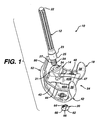
- FIG. 1 is an exploded view of a modular prosthetic joint prosthesis 10 that includes a number of modular components including an elongate stem 12, a collar member 14, a femoral component 18, and an attachment nut 20.
- the construction of the present invention provides several mounting possibilities that are compatible with the various possible orientations of the femoral stem when mounted within the distal portion of the femur.
- the stem 12 has a proximal end 22 and a distal end 24 with a bulged portion 23 disposed between the proximal and distal ends 22, 24.
- the bulged portion 23 includes a distally facing mating shoulder portion 25 adapted for mating with a superior seating surface 31 of collar member 14.
- the distal end 24 of the stem 12 includes a connector portion 27 which extends distally from the bulged position 23.
- the connector portion 27 may have threads formed thereon effective to threadably engage the attachment nut 20, as discussed in more detail later herein.
- the connector portion 27 of stem 12 has an outer diameter substantially smaller than the outer diameter as measured at the bulged portion 23.
- the diameter of the proximal end 22 of sleeve 14 is also less than the outer diameter of the bulged portion 23.
- the stem 12 has a degree of lateral offset between a first longitudinal axis 82 extending through the proximal end 22 and a second longitudinal axis 84 extending through the distal end 24 of stem 12.
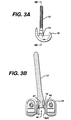
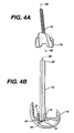
- the lateral offset between the first and second axes 82, 84 can vary depending upon a patient's anatomical requirements, but the offset generally is in the range of 2 to 8 mm. While the embodiment shown and described above allows for offset in either direction of the medial-lateral plane, the embodiment shown in FIGS. 1-4B allows offset placement in the medial-lateral direction, the anterior-posterior direction, and virtually at any position between medial-lateral and anterior-posterior.
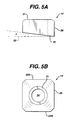
- the collar member 14 has a central body portion 28 that has an outer peripheral surface 29, an inferior boss engaging surface 30 and a superior stem seating surface 31.
- the shoulder portion 25 of stem 12, when assembled with the collar 14, preferably mates with and engages the stem seating surface 31, which is sized to receive femoral stems having various diameters, including diameters of about 6 to 30 mm.
- the boss engaging surface 30 is preferably canted and forms an angle with a transverse plane 32.
- the angle ( ⁇ ) is preferably between about 1° and about 15°.
- the boss engaging surface 30 can be canted in the anterior-posterior direction to either the anterior or posterior side as measured in the sagittal plane.
- the surface 30 can be canted in the medial-lateral direction to either the medial side or the posterior side as measured in the coronal plane.
- the angle ( ⁇ ) can range between about 1° and about 15° in any direction.
- This varied collar angulation provides a plurality of stem mounting angles which is compatible with the various possible orientations of the femoral stem when mounted within the distal portion of the femur.
- the boss mounting surface 30 can be configured to provide any combination of coronal and sagittal plane angulations that are constrained by the foregoing angle ranges.
- the collar 14 can be used with either right or left side knee prostheses. Generally, the collar is positioned such that the angle ( ⁇ ) is to the lateral side of the prosthesis, as measured in the coronal plane. The same collar can be used in either left or right side prosthesis by simply reversing the orientation of the collar on the prosthesis to ensure a lateral angle for the femoral stem 12.
- the collar peripheral surface 29 also has at least one pair of opposed flat sides 29A. Flat sides are adapted to engage raised ridges 44 formed on the top surface 40B of boss structure 40. The mating contact between the raised ridges 44 and the flat sides 29A of the collar peripheral surface 29 prevents unwanted rotation of the collar 14 when mounted on the boss top surface 40B.
- the collar 14 further has a central aperture 34 which receives the distal connector portion end 24 of femoral stem 12.
- the femoral component 18 has a pair of condylar portions 36, 38 that are connected by an intercondylar boss or box structure 40.
- the femoral component 18 also has an articulation surface 42 and an opposed surface 44.
- the femoral component 16 has an anterior side 52 and a posterior side 54.
- the anterior side 52 of the femoral component 16 includes a patellar groove 50 within which seats a patellar prosthetic component (not shown).
- the surfaces 42 of the curved condylar portions 36, 38 articulate with a prosthetic tibial component (not shown) mounted on the head of the tibia, in a manner well known to those of ordinary skill in the art.
- the boss structure 40 has a pair of substantially vertical side walls 40A that are connected by a top or superior, seating surface 40B.
- the boss structure 40 further has a cavity 46 formed within a bottom or inferior surface 40C.
- the cavity 46 is further defined at one end by curved spherical sidewalls 51 which have a complementary shape to mate with and engage attachment nut 20.
- the boss structure 40 further includes an aperture 47 formed thereon which extends between the surfaces 40B, 40C, respectively, of the boss structure 40.
- the shape of the aperture 47 in the boss structure 40 can be elliptical, oval, spherical, or of any other suitable shape that allows a sufficient amount of translation of the securing bolt shaft when the bolt is mounted within the aperture.
- FIG. 1 illustrates the attachment nut 20 useful with the present invention.
- the nut 20 includes a generally spherical top portion 60 and a bottom portion 62.
- a central aperture 64 extends between the top and bottom portions 60, 62.
- threads are formed within an inner surface 66 of the nut 20 effective to threadably engage corresponding threads formed on the distal end of the stem 12.
- the spherical top portion 60 mates with and engages the similarly configured endwall of the femoral boss cavity.
- an exemplary modular knee prosthesis utilizing the component described above can be assembled in the following manner.
- the collar 14 is mounted on the top surface 40B of the boss 40 by aligning and engaging ridges 44 with collar flat sides 29A such that the collar aperture 34 is aligned with box aperture 47.
- the stem 12 is mated to the collar 14 by positioning the distal connector portion 27 through collar aperture 34 so that the mating surface or shoulder 25 rests upon the stem seating surface 31 of the collar 14.
- the distal end 24 of stem 12 is further extended and passed through box aperture 47 such that at least a portion of the connector end 27 protrudes and extends into box cavity 46.
- the attachment nut 20 is inserted into the boss cavity 46 from the underside of the boss structure to threadably engage the distal connector portion 27 of the stem 12.
- the spherical engaging surface 60 of the attachment nut 20 mates with and engages the similarly configured endwall 51 of the boss cavity 46.
- the selected shape of the cavity endwall 51 allows the attachment nut 20 to seat within the cavity 46 at an angle that is determined by the collar 14.
- the boss mounting surface 30 of the collar 14 determines the stem angulation once the components are assembled together.
- the threaded connector portion 27 of the distal end of the stem 12 threadably engages the threaded attachment nut 20 and fixedly secures the stem 12 to the femoral component 18. In this axially successive assemblage, the collar is pressure fitted between the stem and boss by the threaded engagement of the stem and nut.
- FIGS. 6-9 illustrate a prosthesis system 100 which is a variation of system 10 described in FIGS. 1-5B.
- System 100 includes the various components present in FIG. 1, including an elongate stem 112, a femoral component 118 and an attachment nut 120.
- the stem 112 and femoral component 118 differ slightly from the components described above with respect to FIGS. 1-4B.
- the stem 112 allows for the interchanging of stem components having varied angulations to provide a variety of mounting possibilities for the prosthesis.
- the stem 112 includes proximal and distal ends 122, 124 with a boss engaging surface 130 disposed proximal the distal end of the stem.
- the boss engaging surface 130 is preferably canted and forms an angle with the transverse plane 132.
- the boss engaging surface 130 and the top surface 140B of the boss 140 which lies in the transverse plane, form a mounting angle ( ⁇ ) when the stem is assembled with the femoral component and engages the boss top surface.
- the angle ( ⁇ ) is preferably between about 1° and about 15°.
- the boss engaging surface 130 can be canted in the anterior-posterior direction to either the anterior or posterior side as measured in the sagittal plane.
- the boss engaging surface 130 can be canted in the medial-lateral direction to either the medial side or the posterior side as measured in the coronal plane.
- the angle ( ⁇ ) can range between about 1° and about 15° in any direction.
- This varied angulation provides a plurality of stem mounting angles which is compatible with the various possible orientations of the femoral stem when mounted within the distal portion of the femur.
- the boss mounting surface 130 can be configured to provide any combination of coronal and sagittal plane angulations that are constrained by the foregoing angle ranges.
- the stem 112 further includes a connector end portion 127 which extends distally from the boss engaging surface 130.
- the connector end 127 has threads formed thereon effective to threadably engage a corresponding threaded portion of attachment nut 120.
- the connector end 127 may also be laterally offset from a longitudinal axis, not shown, which extends through the proximal end 122 of the stem 112. The offset placement may be in the medial-lateral direction, the anterior-posterior direction, and virtually at any position between medial-lateral and anterior-posterior.
- the femoral component 118 has a pair of condylar portions 136, 138 that are connected by an intercondylar region or boss structure 140.
- the femoral component 118 has an articulation surface 142 and an opposed surface 144. Further, the femoral component 118 also has an anterior side 152 and a posterior side 154.
- the boss structure 140 has a pair of substantially vertical side walls 140A that are generally orthogonal to a top superior surface 140B.
- the top superior surface 140B is substantially horizontally oriented and extends in the transverse plane.
- the transverse plane is defined as the horizontal plane that extends through the knee of an upright subject that is orthogonal to both the coronal plane and the sagittal plane as will be appreciated by those having ordinary skill in the art.
- the top surface 140B has formed thereon a mounting aperture 147 effective to engage the stem member 112, as discussed in more detail later herein.
- the boss 140 further has a cavity 146 formed within a bottom inferior surface 140C.
- An aperture 147 defined by the cavity 146 extends between surfaces 140B, 140C, respectively, of the boss structure 140.
- the top surface 140B is configured to mate with and engage femoral stem 112.
- FIGS. 6 and 7 illustrate an attachment nut 120 useful with this embodiment.
- the nut 120 includes opposed generally horizontal top and bottom surfaces 161, 162 with a generally spherical sidewall 160 extending therebetween.
- the bottom surface 162 has a series of impressions or indentations 121 formed thereon effective to engage a mounting tool, not shown, used to tighten or loosen the nut 120.
- a central aperture 164 extends between the top and bottom surfaces 161, 162. Threads are formed within an inner surface of attachment nut 120 to threadably engage the distal connector end 127 of stem 112.
- the embodiment as described above may be assembled as follows.
- the distal end 124 of stem 112 is passed through box aperture 147 such that a portion of the distal end of the stem 112 extends into femoral box cavity 146.
- the attachment nut 120 is inserted into the boss cavity 146 from the underside of the boss structure to threadably engage the distal connector portion 127 of the stem 112.
- the threaded connector end 127 of stem 112 threadably engages the threaded attachment nut 120 and fixedly secures the stem 112 to the femoral component 118.
- the complementary shape of the cavity endwall 151 and the spherical sidewall 160 of the attachment nut 120 cooperate to position the stem at a selected angle as determined by the boss mounting surface 130.
- the boss mounting surface 130 of the stem determines the stem angulation.
- Various offset configurations are also possible utilizing a distal connector portion 127 which is offset from the longitudinal axis extending through the proximal end of the stem as discussed earlier herein.
Abstract
Description
- The invention relates to medical devices, and more particularly to prosthetic joint components.
- Joint arthroplasty is a well-known surgical procedure by which a diseased and/or damaged natural joint is replaced by a prosthetic joint. A typical knee prosthesis includes a tibial component, a femoral component, a femoral stem assembly, and a patellar component. The femoral component generally includes a pair of spaced apart condylar portions, the superior surfaces of which articulate with a portion of the tibial component. The femoral stem assembly provides lateral stability, and it typically includes a member that is inserted within a reamed intramedullary canal at the distal end of a femur. The stem is typically coupled to the femoral component by a collar and bolt.
- Although modular systems can provide an advantageous reduction in joint component inventory, known systems do not fully address the problems associated with variations in intramedullary canal geometry. Specifically, the variations in the morphology of the intermedullary canal often do not match the geometry of the stem, forcing the surgical positioning of the femoral component that is mated to the stem to be determined by considerations other than the shape of the canal.
- For example, if the implant geometry does not match the canal geometry, the stem of the implant can contact the cortical wall of the intramedullary canal while the stem is being impacted. This problem can be further complicated when a femoral stem is mated to a sleeve that increases the effective length of the stem so that it is in a bowed portion of the intramedullary canal.
- In response to the above problems, a surgeon may be forced to remove the stem (or entire component) and replace it with a stem having a smaller diameter or shorter length, even if the replacement stem is thought to be less suitable than the original stem, but for the improper fit. Also, the surgeon may have to cut notches in the femur to accommodate a shifted femoral component.
- Therefore, despite the existence of joint prostheses having modular components, there remains a need for a modular joint prosthesis that has greater versatility to accommodate differing patient anatomy and joint conditions.
- The present invention relates to a modular knee joint prosthesis having improved versatility. Components of the modular prosthesis of the invention are able to be used with both right and left side prostheses.
- The present invention provides a modular knee prosthesis which includes a femoral component having a pair of spaced apart condylar portions and a boss structure extending between the condylar portions. The boss structure has a top superior surface that extends generally horizontally in a transverse plane and an opposed inferior surface which has a cavity formed therein that terminates in a substantially spherically shaped endwall. The boss structure further includes an aperture which extends between the mounting and securing surfaces of the boss structure. The knee prosthesis further includes a stem component which has a proximal end and a distal end that is mountable through the boss aperture.
- A mounting surface is provided which may be either integrated into the stem component or provided as a separate collar component for varying the angulation of the stem component relative to the femoral component. The mounting surface is oriented substantially transverse to a longitudinal axis of the stem member such that the mounting surface and the top surface of the boss structure define a selected mounting angle therebetween. Finally, the knee prosthesis includes an attachment nut having a spherically shaped superior surface for engaging the spherically shaped endwall of the boss structure to secure the stem member to the femoral component.
- A more complete understanding of the present invention and the attendant advantages and features thereof will be more readily understood by reference to the following detailed description when considered in conjunction with the accompanying drawings wherein:
- FIG. 1 is an exploded view of a multi-piece prosthetic joint component system;
- FIG. 2 is an assembled view of the joint component system shown in FIG. 1;
- FIG. 3A is a side view of the joint component system of FIG. 1;
- FIG. 3B is a sectional view of the joint component system taken along
line 3B-3B in FIG. 3A; - FIG. 4A is a front view of the joint component system of FIG. 1;
- FIG. 4B is a sectional view of the joint component system taken along
line 4B-4B in FIG. 4A; - FIG. 5A is a side view of the collar member of FIG. 1;
- FIG. 5B is a top view of the collar member of FIG. 5A;
- FIG. 6 is an exploded view of an alternative embodiment of the multi-piece prosthetic joint component system;
- FIG. 7 is a bottom view of the joint component system shown in FIG. 6;
- FIG. 8A is a side view of the joint component system shown in FIG.6;
- FIG. 8B is a sectional view of the joint component system taken along
line 8B-8B in FIG. 8A; and - FIG. 9 is a detailed side view of portion A in FIG. 6.
-
- FIG. 1 is an exploded view of a modular
prosthetic joint prosthesis 10 that includes a number of modular components including anelongate stem 12, acollar member 14, afemoral component 18, and anattachment nut 20. The construction of the present invention provides several mounting possibilities that are compatible with the various possible orientations of the femoral stem when mounted within the distal portion of the femur. - Referring to FIGS. 1-4B, the
stem 12 has aproximal end 22 and adistal end 24 with a bulgedportion 23 disposed between the proximal anddistal ends portion 23 includes a distally facingmating shoulder portion 25 adapted for mating with asuperior seating surface 31 ofcollar member 14. Thedistal end 24 of thestem 12 includes aconnector portion 27 which extends distally from thebulged position 23. Theconnector portion 27 may have threads formed thereon effective to threadably engage theattachment nut 20, as discussed in more detail later herein. In an exemplary embodiment, theconnector portion 27 ofstem 12 has an outer diameter substantially smaller than the outer diameter as measured at the bulgedportion 23. Preferably, the diameter of theproximal end 22 ofsleeve 14 is also less than the outer diameter of the bulgedportion 23. - In an exemplary embodiment as shown in FIG. 4B, the
stem 12 has a degree of lateral offset between a firstlongitudinal axis 82 extending through theproximal end 22 and a secondlongitudinal axis 84 extending through thedistal end 24 ofstem 12. The lateral offset between the first andsecond axes - With reference to FIGS. 1, 2 and 5A-5B, the
collar member 14 has acentral body portion 28 that has an outerperipheral surface 29, an inferiorboss engaging surface 30 and a superiorstem seating surface 31. Theshoulder portion 25 ofstem 12, when assembled with thecollar 14, preferably mates with and engages thestem seating surface 31, which is sized to receive femoral stems having various diameters, including diameters of about 6 to 30 mm. - The
boss engaging surface 30 is preferably canted and forms an angle with atransverse plane 32. Theboss engaging surface 30 and atop surface 40B ofboss structure 40 which lies in the transverse plane, form a mounting angle (α) when the collar is assembled with the femoral component and engages theboss top surface 40B. The angle (α) is preferably between about 1° and about 15°. According to one practice of the invention, theboss engaging surface 30 can be canted in the anterior-posterior direction to either the anterior or posterior side as measured in the sagittal plane. Likewise, thesurface 30 can be canted in the medial-lateral direction to either the medial side or the posterior side as measured in the coronal plane. Preferably, the angle (α) can range between about 1° and about 15° in any direction. This varied collar angulation provides a plurality of stem mounting angles which is compatible with the various possible orientations of the femoral stem when mounted within the distal portion of the femur. Those of ordinary skill in the art readily appreciate that theboss mounting surface 30 can be configured to provide any combination of coronal and sagittal plane angulations that are constrained by the foregoing angle ranges. - The
collar 14 can be used with either right or left side knee prostheses. Generally, the collar is positioned such that the angle (α) is to the lateral side of the prosthesis, as measured in the coronal plane. The same collar can be used in either left or right side prosthesis by simply reversing the orientation of the collar on the prosthesis to ensure a lateral angle for thefemoral stem 12. - The collar
peripheral surface 29 also has at least one pair of opposedflat sides 29A. Flat sides are adapted to engage raisedridges 44 formed on thetop surface 40B ofboss structure 40. The mating contact between the raisedridges 44 and theflat sides 29A of the collarperipheral surface 29 prevents unwanted rotation of thecollar 14 when mounted on theboss top surface 40B. Thecollar 14 further has acentral aperture 34 which receives the distalconnector portion end 24 offemoral stem 12. - Referring to FIGS. 1-4B, the
femoral component 18 has a pair ofcondylar portions box structure 40. Thefemoral component 18 also has anarticulation surface 42 and anopposed surface 44. Further, the femoral component 16 has ananterior side 52 and aposterior side 54. Theanterior side 52 of the femoral component 16 includes apatellar groove 50 within which seats a patellar prosthetic component (not shown). Thesurfaces 42 of the curvedcondylar portions - The
boss structure 40 has a pair of substantiallyvertical side walls 40A that are connected by a top or superior,seating surface 40B. Theboss structure 40 further has acavity 46 formed within a bottom orinferior surface 40C. Thecavity 46 is further defined at one end by curvedspherical sidewalls 51 which have a complementary shape to mate with and engageattachment nut 20. Once the prosthesis is assembled, thesidewalls 51 engageattachment nut 20 so that the femoral stem is secured at a desired angulation, as discussed in more detail later herein. - The
boss structure 40 further includes anaperture 47 formed thereon which extends between thesurfaces boss structure 40. The shape of theaperture 47 in theboss structure 40 can be elliptical, oval, spherical, or of any other suitable shape that allows a sufficient amount of translation of the securing bolt shaft when the bolt is mounted within the aperture. - FIG. 1 illustrates the
attachment nut 20 useful with the present invention. Thenut 20 includes a generally sphericaltop portion 60 and abottom portion 62. Acentral aperture 64 extends between the top andbottom portions inner surface 66 of thenut 20 effective to threadably engage corresponding threads formed on the distal end of thestem 12. The sphericaltop portion 60 mates with and engages the similarly configured endwall of the femoral boss cavity. - Referring to FIGS. 1-5B, an exemplary modular knee prosthesis utilizing the component described above can be assembled in the following manner. The
collar 14 is mounted on thetop surface 40B of theboss 40 by aligning and engagingridges 44 with collarflat sides 29A such that thecollar aperture 34 is aligned withbox aperture 47. Thestem 12 is mated to thecollar 14 by positioning thedistal connector portion 27 throughcollar aperture 34 so that the mating surface orshoulder 25 rests upon thestem seating surface 31 of thecollar 14. Thedistal end 24 ofstem 12 is further extended and passed throughbox aperture 47 such that at least a portion of theconnector end 27 protrudes and extends intobox cavity 46. Theattachment nut 20 is inserted into theboss cavity 46 from the underside of the boss structure to threadably engage thedistal connector portion 27 of thestem 12. - In such a configuration, the spherical engaging
surface 60 of theattachment nut 20 mates with and engages the similarly configuredendwall 51 of theboss cavity 46. The selected shape of thecavity endwall 51 allows theattachment nut 20 to seat within thecavity 46 at an angle that is determined by thecollar 14. In such a configuration, theboss mounting surface 30 of thecollar 14 determines the stem angulation once the components are assembled together. The threadedconnector portion 27 of the distal end of thestem 12 threadably engages the threadedattachment nut 20 and fixedly secures thestem 12 to thefemoral component 18. In this axially successive assemblage, the collar is pressure fitted between the stem and boss by the threaded engagement of the stem and nut. - FIGS. 6-9 illustrate a
prosthesis system 100 which is a variation ofsystem 10 described in FIGS. 1-5B.System 100 includes the various components present in FIG. 1, including anelongate stem 112, afemoral component 118 and anattachment nut 120. - The
stem 112 andfemoral component 118 differ slightly from the components described above with respect to FIGS. 1-4B. In this embodiment, thestem 112 allows for the interchanging of stem components having varied angulations to provide a variety of mounting possibilities for the prosthesis. Thestem 112 includes proximal anddistal ends boss engaging surface 130 disposed proximal the distal end of the stem. - Referring to FIG. 9, the
boss engaging surface 130 is preferably canted and forms an angle with thetransverse plane 132. Theboss engaging surface 130 and thetop surface 140B of theboss 140, which lies in the transverse plane, form a mounting angle () when the stem is assembled with the femoral component and engages the boss top surface. The angle () is preferably between about 1° and about 15°. According to one practice of the invention, theboss engaging surface 130 can be canted in the anterior-posterior direction to either the anterior or posterior side as measured in the sagittal plane. Likewise, theboss engaging surface 130 can be canted in the medial-lateral direction to either the medial side or the posterior side as measured in the coronal plane. Preferably, the angle () can range between about 1° and about 15° in any direction. This varied angulation provides a plurality of stem mounting angles which is compatible with the various possible orientations of the femoral stem when mounted within the distal portion of the femur. Those of ordinary skill in the art readily appreciate that theboss mounting surface 130 can be configured to provide any combination of coronal and sagittal plane angulations that are constrained by the foregoing angle ranges. - The
stem 112 further includes aconnector end portion 127 which extends distally from theboss engaging surface 130. Preferably, theconnector end 127 has threads formed thereon effective to threadably engage a corresponding threaded portion ofattachment nut 120. Theconnector end 127 may also be laterally offset from a longitudinal axis, not shown, which extends through theproximal end 122 of thestem 112. The offset placement may be in the medial-lateral direction, the anterior-posterior direction, and virtually at any position between medial-lateral and anterior-posterior. - Referring to FIGS. 6-8B, the
femoral component 118 has a pair ofcondylar portions boss structure 140. Thefemoral component 118 has anarticulation surface 142 and anopposed surface 144. Further, thefemoral component 118 also has ananterior side 152 and aposterior side 154. - The
boss structure 140 has a pair of substantiallyvertical side walls 140A that are generally orthogonal to a topsuperior surface 140B. The topsuperior surface 140B is substantially horizontally oriented and extends in the transverse plane. The transverse plane is defined as the horizontal plane that extends through the knee of an upright subject that is orthogonal to both the coronal plane and the sagittal plane as will be appreciated by those having ordinary skill in the art. - The
top surface 140B has formed thereon a mountingaperture 147 effective to engage thestem member 112, as discussed in more detail later herein. Theboss 140 further has acavity 146 formed within a bottominferior surface 140C. Anaperture 147 defined by thecavity 146 extends betweensurfaces boss structure 140. As illustrated, thetop surface 140B is configured to mate with and engagefemoral stem 112. - FIGS. 6 and 7 illustrate an
attachment nut 120 useful with this embodiment. Thenut 120 includes opposed generally horizontal top andbottom surfaces spherical sidewall 160 extending therebetween. Thebottom surface 162 has a series of impressions orindentations 121 formed thereon effective to engage a mounting tool, not shown, used to tighten or loosen thenut 120. Acentral aperture 164 extends between the top andbottom surfaces attachment nut 120 to threadably engage thedistal connector end 127 ofstem 112. - The embodiment as described above may be assembled as follows. The
distal end 124 ofstem 112 is passed throughbox aperture 147 such that a portion of the distal end of thestem 112 extends intofemoral box cavity 146. Theattachment nut 120 is inserted into theboss cavity 146 from the underside of the boss structure to threadably engage thedistal connector portion 127 of thestem 112. The threadedconnector end 127 ofstem 112 threadably engages the threadedattachment nut 120 and fixedly secures thestem 112 to thefemoral component 118. In such an engagement, the complementary shape of the cavity endwall 151 and thespherical sidewall 160 of theattachment nut 120 cooperate to position the stem at a selected angle as determined by theboss mounting surface 130. Once the components are assembled, theboss mounting surface 130 of the stem determines the stem angulation. Various offset configurations are also possible utilizing adistal connector portion 127 which is offset from the longitudinal axis extending through the proximal end of the stem as discussed earlier herein. - A variety of modifications and variations of the present invention are possible in light of the above teachings. It is also understood that the basic femoral component construction in the present system can be used for either the right or left knee. All references cited herein are expressly incorporated by reference in their entirety.
Claims (16)
- A modular knee prosthesis comprising:a first component having a pair of spaced apart condylar portions and a boss structure extending between the condylar portions, the boss structure having a superior mounting surface that extends generally horizontally in a transverse plane and an opposed inferior surface having a cavity formed therein that terminates in a substantially spherically shaped endwall, wherein an aperture extends between the superior mounting and inferior surfaces of the boss structure;a second component having a distal mounting surface mountable on the superior mounting surface of the boss structure, the distal mounting surface of the second component and superior mounting surface of the boss structure defining a selected mounting angle therebetween; anda third component for securing the second component to the first component, the third component having a spherically shaped superior surface for engaging the spherically shaped endwall of the boss structure.
- The knee prosthesis of claim 1, wherein the second component is an elongate stem and the third component is an attachment nut.
- The knee prosthesis of claim 2, wherein at least a portion of the stem is threaded so as to threadably engage the attachment nut.
- The knee prosthesis of claim 3, wherein the distal end of the stem component is offset a selected distance in the transverse plane relative to the proximal end of the stem.
- The knee prosthesis of claim 1, wherein the second component is a collar having a body portion with an aperture extending therethrough and the third component is an attachment nut.
- The knee prosthesis of claim 5, wherein the knee prosthesis further comprises a stem component having a proximal end and a distal end which is mountable through the collar aperture and further extends into and through the boss aperture.
- The knee prothesis of claim 6, wherein the collar is positionable between the stem component and the femoral boss structure.
- The knee prosthesis of claim 7, wherein the boss structure includes an anti-rotation means for preventing rotation of the collar when mounted on the boss structure.
- The knee prosthesis of claim 1, wherein the mounting angle of the mounting surface of the second component is in the range of 1° to about 15° in the medial-lateral direction in the transverse plane, to the medial or lateral side.
- A modular knee prosthesis comprising:a femoral component having a pair of spaced apart condylar portion and a boss structure extending between the condylar portions, the boss structure having a superior mounting surface that extends generally horizontally in a transverse plane and an opposed inferior surface having a cavity formed therein that terminates in a substantially spherically shaped endwall, wherein an aperture extends between the superior and inferior surfaces of the boss structure;a stem component having a proximal end and a distal end;a collar member mountable on the superior surface of the boss structure, the collar member having a superior and an inferior surface that is substantially transverse to a longitudinal axis of the stem member when mounted thereon, the collar inferior surface and the superior mounting surface of the boss structure defining a selected mounting angle therebetween, the collar member further having an aperture extending between the superior and inferior surfaces; andan attachment nut for securing the stem member and collar member to the femoral component.
- The knee prosthesis of claim 10, wherein the mounting angle of the inferior surface of the collar is in the range of 1° and about 15° in the medial-lateral direction in the transverse plane, to the medial or lateral side.
- The knee prosthesis of claim 10, wherein the boss structure includes an anti-rotation means for preventing rotation of the collar when mounted on the boss structure.
- The knee prosthesis of claim 10, wherein at least a portion of the distal end of the stem component is threaded so as to threadably engage the attachment nut.
- The knee prosthesis of claim 10, wherein the distal end of the stem component is offset a selected distance in the transverse plane relative to the proximal end of the stem.
- The knee prosthesis of claim 10, wherein the attachment nut has spherically shaped superior surface for engaging the spherically shaped endwall of the boss structure.
- A modular knee prosthesis comprising:a femoral component having a pair of spaced apart condylar portions and a boss structure extending between the condylar portions, the boss structure having a top surface that extends generally horizontally in a transverse plane and an opposed bottom surface having a cavity formed therein that terminates in a substantially spherically shaped endwall, wherein an aperture extends between the top and bottom surfaces of the boss structure;a stem component having a proximal end and a distal end that is mountable through the boss aperture, the distal end of the stem further including a mounting surface which along with the top surface of the boss structure defines a selected mounting angle therebetween; andan attachment nut having a spherically shaped superior surface for engaging the spherically shaped endwall of the boss structure for securing the stem member to the femoral component.
Applications Claiming Priority (2)
| Application Number | Priority Date | Filing Date | Title |
|---|---|---|---|
| US150122 | 1998-09-09 | ||
| US09/150,122 US6527807B1 (en) | 1998-09-09 | 1998-09-09 | Femoral stem attachment for a modular knee prosthesis |
Publications (3)
| Publication Number | Publication Date |
|---|---|
| EP0985386A2 true EP0985386A2 (en) | 2000-03-15 |
| EP0985386A3 EP0985386A3 (en) | 2002-03-20 |
| EP0985386B1 EP0985386B1 (en) | 2006-11-22 |
Family
ID=22533206
Family Applications (1)
| Application Number | Title | Priority Date | Filing Date |
|---|---|---|---|
| EP99307120A Expired - Lifetime EP0985386B1 (en) | 1998-09-09 | 1999-09-08 | Femoral stem attachment for a modular knee prosthesis |
Country Status (4)
| Country | Link |
|---|---|
| US (1) | US6527807B1 (en) |
| EP (1) | EP0985386B1 (en) |
| JP (1) | JP4118472B2 (en) |
| DE (1) | DE69934060T2 (en) |
Cited By (20)
| Publication number | Priority date | Publication date | Assignee | Title |
|---|---|---|---|---|
| EP0980679A3 (en) * | 1998-08-14 | 2002-03-13 | JOHNSON & JOHNSON PROFESSIONAL Inc. | Femoral component of a modular knee prosthesis |
| EP1132064A3 (en) * | 2000-03-06 | 2003-03-19 | Louis A. Serafin | Modular joint prosthesis |
| EP1430856A1 (en) * | 2002-12-20 | 2004-06-23 | Depuy Products, Inc. | Modular prosthetic knee implant system comprising femoral stem augment |
| WO2007023196A1 (en) | 2005-07-06 | 2007-03-01 | German Perez Cosias | Whole knee prosthesis |
| US7462199B2 (en) | 2003-12-30 | 2008-12-09 | Medicinelodge, Inc. | Methods for mounting a tibial condylar implant |
| US7867280B2 (en) | 2003-12-30 | 2011-01-11 | Zimmer, Inc. | Methods for mounting and using tethered joint bearing implants |
| US7896922B2 (en) | 2001-06-14 | 2011-03-01 | Alexandria Research Technologies, Llc | Implants for partial knee arthroplasty |
| US7922772B2 (en) | 2002-05-24 | 2011-04-12 | Zimmer, Inc. | Implants and related methods and apparatus for securing an implant on an articulating surface of an orthopedic joint |
| US8048163B2 (en) | 2002-02-20 | 2011-11-01 | Zimmer, Inc. | Knee arthroplasty prosthesis |
| US8157869B2 (en) | 2007-01-10 | 2012-04-17 | Biomet Manufacturing Corp. | Knee joint prosthesis system and method for implantation |
| US8157867B2 (en) | 2004-07-09 | 2012-04-17 | Zimmer, Inc. | Trochlear groove implants and related methods and instruments |
| US8163028B2 (en) | 2007-01-10 | 2012-04-24 | Biomet Manufacturing Corp. | Knee joint prosthesis system and method for implantation |
| US8187280B2 (en) | 2007-10-10 | 2012-05-29 | Biomet Manufacturing Corp. | Knee joint prosthesis system and method for implantation |
| US8197550B2 (en) | 2005-04-21 | 2012-06-12 | Biomet Manufacturing Corp. | Method and apparatus for use of porous implants |
| US8328873B2 (en) | 2007-01-10 | 2012-12-11 | Biomet Manufacturing Corp. | Knee joint prosthesis system and method for implantation |
| US8460391B2 (en) | 2002-05-24 | 2013-06-11 | Zimmer, Inc. | Modular femoral components for knee arthroplasty |
| US8540775B2 (en) | 2007-06-11 | 2013-09-24 | Aesculap Ag | Modular implant part and knee joint prosthesis |
| US8551181B2 (en) | 2001-02-23 | 2013-10-08 | Biomet Manufacturing, Llc | Method and apparatus for acetabular reconstruction |
| US8562616B2 (en) | 2007-10-10 | 2013-10-22 | Biomet Manufacturing, Llc | Knee joint prosthesis system and method for implantation |
| US9044328B2 (en) | 2008-03-07 | 2015-06-02 | Aesculap Ag | Medical implant and knee joint endoprosthesis |
Families Citing this family (44)
| Publication number | Priority date | Publication date | Assignee | Title |
|---|---|---|---|---|
| US7497874B1 (en) * | 2001-02-23 | 2009-03-03 | Biomet Manufacturing Corp. | Knee joint prosthesis |
| GB0204381D0 (en) * | 2002-02-26 | 2002-04-10 | Mcminn Derek J W | Knee prosthesis |
| WO2004037119A2 (en) | 2002-10-23 | 2004-05-06 | Mako Surgical Corp. | Modular femoral component for a total knee joint replacement for minimally invasive implantation |
| US8052756B2 (en) * | 2002-10-24 | 2011-11-08 | Biomet Manufacturing Corp. | Method and apparatus for wrist arthroplasty |
| US6746486B1 (en) * | 2002-10-24 | 2004-06-08 | Biomet, Inc. | Method and apparatus for total wrist angled back carpal plate |
| US8372154B2 (en) * | 2002-10-24 | 2013-02-12 | Biomet Manufacturing Corp. | Method and apparatus for wrist arthroplasty |
| US8821581B2 (en) * | 2002-10-24 | 2014-09-02 | Biomet Manufacturing, Llc | Method and apparatus for wrist arthroplasty |
| US8105388B2 (en) * | 2002-10-24 | 2012-01-31 | Biomet Manufacturing Corp. | Method and apparatus for wrist arthroplasty |
| US8105390B2 (en) | 2002-10-24 | 2012-01-31 | Biomet Manufacturing Corp. | Method and apparatus for wrist arthroplasty |
| US8066777B2 (en) * | 2002-10-24 | 2011-11-29 | Biomet Manufacturing Corp. | Method and apparatus for wrist arthroplasty |
| US8105389B2 (en) * | 2002-10-24 | 2012-01-31 | Biomet Manufacturing Corp. | Method and apparatus for wrist arthroplasty |
| US8940055B2 (en) | 2002-10-24 | 2015-01-27 | Biomet Manufacturing, Llc | Method and apparatus for wrist arthroplasty |
| US7799085B2 (en) * | 2003-11-18 | 2010-09-21 | Depuy Products, Inc. | Modular implant system with fully porous coated sleeve |
| US7727281B2 (en) | 2003-12-08 | 2010-06-01 | Ortho Development Corporation | Modular femoral knee stem extender |
| US7544209B2 (en) | 2004-01-12 | 2009-06-09 | Lotke Paul A | Patello-femoral prosthesis |
| US7258701B2 (en) * | 2004-01-12 | 2007-08-21 | Depuy Products, Inc. | Systems and methods for compartmental replacement in a knee |
| US8002840B2 (en) | 2004-01-12 | 2011-08-23 | Depuy Products, Inc. | Systems and methods for compartmental replacement in a knee |
| US8535383B2 (en) * | 2004-01-12 | 2013-09-17 | DePuy Synthes Products, LLC | Systems and methods for compartmental replacement in a knee |
| WO2005117763A2 (en) * | 2004-05-28 | 2005-12-15 | Smith & Nephew, Inc. | Fluted intramedullary stem |
| US7892290B2 (en) * | 2004-05-28 | 2011-02-22 | Smith & Nephew, Inc. | Fluted sleeve hip prosthesis for modular stem |
| JP4659044B2 (en) * | 2004-12-17 | 2011-03-30 | デピュイ・プロダクツ・インコーポレイテッド | Modular shaft and collar implant |
| US7867282B2 (en) * | 2004-12-17 | 2011-01-11 | Depuy Products, Inc. | Modular implant system and method with diaphyseal implant and adapter |
| US7507256B2 (en) * | 2004-12-17 | 2009-03-24 | Depuy Products, Inc. | Modular implant system and method with diaphyseal implant |
| CA2598027C (en) * | 2005-02-22 | 2013-10-01 | Smith & Nephew, Inc. | Long sleeves for use with stems |
| US8266780B2 (en) | 2005-04-21 | 2012-09-18 | Biomet Manufacturing Corp. | Method and apparatus for use of porous implants |
| US8066778B2 (en) | 2005-04-21 | 2011-11-29 | Biomet Manufacturing Corp. | Porous metal cup with cobalt bearing surface |
| US8292967B2 (en) | 2005-04-21 | 2012-10-23 | Biomet Manufacturing Corp. | Method and apparatus for use of porous implants |
| US8021432B2 (en) | 2005-12-05 | 2011-09-20 | Biomet Manufacturing Corp. | Apparatus for use of porous implants |
| US8211181B2 (en) * | 2005-12-14 | 2012-07-03 | New York University | Surface guided knee replacement |
| US20070135924A1 (en) * | 2005-12-14 | 2007-06-14 | Verhoogen Alex R | Joint replacement prosthesis, joint replacement mounting stud and method |
| US8292964B2 (en) * | 2005-12-14 | 2012-10-23 | New York University | Surface guided knee replacement |
| US7635447B2 (en) * | 2006-02-17 | 2009-12-22 | Biomet Manufacturing Corp. | Method and apparatus for forming porous metal implants |
| US7806936B2 (en) * | 2006-10-19 | 2010-10-05 | Depuy Products, Inc. | Bowed femoral sleeve |
| US8050786B2 (en) * | 2007-07-11 | 2011-11-01 | Stratasys, Inc. | Method for building three-dimensional objects with thin wall regions |
| US8382846B2 (en) | 2007-08-27 | 2013-02-26 | Kent M. Samuelson | Systems and methods for providing deeper knee flexion capabilities for knee prosthesis patients |
| US9872774B2 (en) | 2007-08-27 | 2018-01-23 | Connor E. Samuelson | Systems and methods for providing a femoral component having a modular stem |
| US8292965B2 (en) * | 2008-02-11 | 2012-10-23 | New York University | Knee joint with a ramp |
| US8298288B2 (en) * | 2008-06-24 | 2012-10-30 | New York University | Recess-ramp knee joint prosthesis |
| US8932364B2 (en) | 2010-07-14 | 2015-01-13 | Howmedica Osteonics Corp. | Prosthetic knee void filers with splined fixation |
| US8403994B2 (en) | 2011-01-19 | 2013-03-26 | Wright Medical Technology, Inc. | Knee implant system |
| US8961612B2 (en) | 2012-08-30 | 2015-02-24 | Biomet Manufacturing, Llc | Knee component having orbital interface boss |
| US9532879B2 (en) | 2012-09-20 | 2017-01-03 | Depuy Ireland Unlimited Company | Femoral knee prosthesis system with augments and multiple lengths of sleeves sharing a common geometry |
| US9320603B2 (en) | 2012-09-20 | 2016-04-26 | Depuy (Ireland) | Surgical instrument system with multiple lengths of broaches sharing a common geometry |
| US8998996B2 (en) | 2012-09-20 | 2015-04-07 | Depuy (Ireland) | Knee prosthesis system with standard and distal offset joint line |
Family Cites Families (51)
| Publication number | Priority date | Publication date | Assignee | Title |
|---|---|---|---|---|
| DE473375C (en) | 1929-03-14 | Albert Schnellpressen | Screw for tightening and adjusting two machine parts with an eccentric head | |
| DE820739C (en) | 1949-09-14 | 1951-11-12 | Hansens Gummi & Packungs Werke | Electrical rail insulation for the railway superstructure |
| DE1575278A1 (en) | 1967-02-11 | 1970-01-15 | Seidner Maschf E | Machine frame made of prestressed concrete |
| US4219893A (en) | 1977-09-01 | 1980-09-02 | United States Surgical Corporation | Prosthetic knee joint |
| US4301553A (en) | 1975-08-15 | 1981-11-24 | United States Surgical Corporation | Prosthetic knee joint |
| IE50750B1 (en) | 1980-03-11 | 1986-07-09 | Howmedica | A set for assembly into a modular prosthesis |
| US4624673A (en) | 1982-01-21 | 1986-11-25 | United States Medical Corporation | Device system for dental prosthesis fixation to bone |
| US4578081A (en) | 1982-02-17 | 1986-03-25 | Howmedica International, Inc. | Bone prosthesis |
| US4790854A (en) | 1982-02-17 | 1988-12-13 | Howmedica International Inc. | Bone prosthesis assembly |
| US4502160A (en) | 1983-10-27 | 1985-03-05 | Dow Corning Wright | Adjustable length prosthetic joint implant |
| US4846839A (en) | 1984-02-09 | 1989-07-11 | Joint Medical Products Corporation | Apparatus for affixing a prosthesis to bone |
| DE3435243C1 (en) | 1984-09-26 | 1986-03-13 | S + G Implants GmbH, 2400 Lübeck | Femoral prosthesis part of a knee joint endoprosthesis |
| GB8501907D0 (en) * | 1985-01-25 | 1985-02-27 | Thackray C F Ltd | Surgical instruments |
| US4790852A (en) | 1986-09-15 | 1988-12-13 | Joint Medical Products Corporation | Sleeves for affixing artificial joints to bone |
| US4822366A (en) * | 1986-10-16 | 1989-04-18 | Boehringer Mannheim Corporation | Modular knee prosthesis |
| DE3730928A1 (en) | 1987-09-15 | 1989-03-23 | S & G Implants Gmbh | KNEE-ENDOPROTHESIS |
| US5057111A (en) | 1987-11-04 | 1991-10-15 | Park Joon B | Non-stress-shielding bone fracture healing device |
| US5194066A (en) | 1988-01-11 | 1993-03-16 | Boehringer Mannheim Corporation | Modular joint prosthesis |
| US4888021A (en) | 1988-02-02 | 1989-12-19 | Joint Medical Products Corporation | Knee and patellar prosthesis |
| US5011496A (en) | 1988-02-02 | 1991-04-30 | Joint Medical Products Corporation | Prosthetic joint |
| US4834758A (en) | 1988-05-26 | 1989-05-30 | New York Society For The Relief Of The Ruptured And Crippled, Maintaining The Hospital For Special Surgery | Bone prosthesis for the leg and thigh |
| US4904110A (en) | 1988-06-17 | 1990-02-27 | Unarco Industries, Inc. | Fastening arrangement for shelving system or the like |
| US4944757A (en) | 1988-11-07 | 1990-07-31 | Martinez David M | Modulator knee prosthesis system |
| GR1000566B (en) | 1988-12-27 | 1992-08-26 | Johnson & Johnson Orthopaedics | Independent knee prosthesis which can be replaced |
| US4936847A (en) * | 1988-12-27 | 1990-06-26 | Johnson & Johnson Orthopaedics, Inc. | Revision knee prosthesis |
| US4936853A (en) | 1989-01-11 | 1990-06-26 | Kirschner Medical Corporation | Modular knee prosthesis |
| IT1232572B (en) | 1989-02-10 | 1992-02-26 | Calderale Pasquale Mario | MEANS OF OSTEOSYNTHESIS FOR THE CONNECTION OF BONE FRACTURE SEGMENTS |
| US4985037A (en) | 1989-05-22 | 1991-01-15 | Petersen Thomas D | Universal modular prosthesis stem extension |
| US5019103A (en) | 1990-02-05 | 1991-05-28 | Boehringer Mannheim Corporation | Tibial wedge system |
| US5133760A (en) | 1990-02-12 | 1992-07-28 | Alvarado Orthopedic Research, Inc. | Universal modular prosthesis stem extension |
| DE4028510C2 (en) | 1990-09-07 | 1994-12-01 | Link Waldemar Gmbh Co | Endoprosthesis |
| US5370701A (en) | 1990-09-28 | 1994-12-06 | Arch Development Corporation | Rotating/sliding contrained prosthetic knee |
| WO1992020306A1 (en) | 1991-05-24 | 1992-11-26 | Kerry Zang | Bone fastening device |
| IT1253545B (en) | 1991-08-08 | 1995-08-08 | KNEE PROSTHESIS EQUIPPED WITH ARTICULATION BETWEEN FEMORAL AND TIBIAL COMPONENTS AND THE RESPECTIVE ENDOMIDOLLAR PHYTHONES | |
| DE4128171C1 (en) | 1991-08-24 | 1993-04-01 | Aesculap Ag, 7200 Tuttlingen, De | |
| AU2037692A (en) | 1991-09-03 | 1993-03-18 | Bristol-Myers Squibb Company | Modular implant and method of assembly |
| FR2684290B1 (en) | 1991-11-29 | 1994-01-21 | Tornier Ets | KNEE PROSTHESIS. |
| CH686339A5 (en) * | 1991-12-10 | 1996-03-15 | Synthes Ag | Nut for the plate fixation. |
| GB9201231D0 (en) | 1992-01-21 | 1992-03-11 | Howmedica | Tibial element for a replacement knee prosthesis |
| US5330534A (en) | 1992-02-10 | 1994-07-19 | Biomet, Inc. | Knee joint prosthesis with interchangeable components |
| US5290313A (en) * | 1992-11-23 | 1994-03-01 | Zimmer, Inc. | Offset prosthetic stem extension |
| US5397360A (en) | 1993-02-11 | 1995-03-14 | Osteonics Corp. | Modular components for prosthetic implants |
| US5387239A (en) | 1993-04-19 | 1995-02-07 | Wright Medical Technology, Inc. | Adjustable length prosthetic implant |
| US5405395A (en) | 1993-05-03 | 1995-04-11 | Wright Medical Technology, Inc. | Modular femoral implant |
| US5556433A (en) * | 1994-12-01 | 1996-09-17 | Johnson & Johnson Professional, Inc. | Modular knee prosthesis |
| US5609641A (en) | 1995-01-31 | 1997-03-11 | Smith & Nephew Richards Inc. | Tibial prosthesis |
| US5733292A (en) | 1995-09-15 | 1998-03-31 | Midwest Orthopaedic Research Foundation | Arthroplasty trial prosthesis alignment devices and associated methods |
| US5683472A (en) * | 1995-12-29 | 1997-11-04 | Johnson & Johnson Professional, Inc. | Femoral stem attachment for a modular knee prosthesis |
| US5782921A (en) * | 1996-07-23 | 1998-07-21 | Johnson & Johnson Professional, Inc. | Modular knee prosthesis |
| US5895428A (en) * | 1996-11-01 | 1999-04-20 | Berry; Don | Load bearing spinal joint implant |
| US6162255A (en) * | 1998-10-15 | 2000-12-19 | Depuy Orthopaedics, Inc. | Stem offset mechanism for joint prosthesis |
-
1998
- 1998-09-09 US US09/150,122 patent/US6527807B1/en not_active Expired - Lifetime
-
1999
- 1999-09-08 JP JP25462899A patent/JP4118472B2/en not_active Expired - Lifetime
- 1999-09-08 DE DE69934060T patent/DE69934060T2/en not_active Expired - Lifetime
- 1999-09-08 EP EP99307120A patent/EP0985386B1/en not_active Expired - Lifetime
Non-Patent Citations (1)
| Title |
|---|
| None |
Cited By (35)
| Publication number | Priority date | Publication date | Assignee | Title |
|---|---|---|---|---|
| EP0980679A3 (en) * | 1998-08-14 | 2002-03-13 | JOHNSON & JOHNSON PROFESSIONAL Inc. | Femoral component of a modular knee prosthesis |
| US6629999B1 (en) | 1999-03-08 | 2003-10-07 | Louis A. Serafin, Jr. | Modular joint |
| EP1132064A3 (en) * | 2000-03-06 | 2003-03-19 | Louis A. Serafin | Modular joint prosthesis |
| US8551181B2 (en) | 2001-02-23 | 2013-10-08 | Biomet Manufacturing, Llc | Method and apparatus for acetabular reconstruction |
| US9375316B2 (en) | 2001-02-23 | 2016-06-28 | Biomet Manufacturing, Llc. | Method and apparatus for acetabular reconstruction |
| US7896922B2 (en) | 2001-06-14 | 2011-03-01 | Alexandria Research Technologies, Llc | Implants for partial knee arthroplasty |
| US8048163B2 (en) | 2002-02-20 | 2011-11-01 | Zimmer, Inc. | Knee arthroplasty prosthesis |
| US9072605B2 (en) | 2002-02-20 | 2015-07-07 | Zimmer, Inc. | Knee arthroplasty prosthesis |
| US8092545B2 (en) | 2002-02-20 | 2012-01-10 | Zimmer, Inc. | Knee arthroplasty prosthesis method |
| US8092546B2 (en) | 2002-02-20 | 2012-01-10 | Zimmer, Inc. | Knee arthroplasty prosthesis |
| US8460391B2 (en) | 2002-05-24 | 2013-06-11 | Zimmer, Inc. | Modular femoral components for knee arthroplasty |
| US7922772B2 (en) | 2002-05-24 | 2011-04-12 | Zimmer, Inc. | Implants and related methods and apparatus for securing an implant on an articulating surface of an orthopedic joint |
| US6869447B2 (en) | 2002-12-20 | 2005-03-22 | Depuy Products, Inc. | Prosthetic knee implant with modular augment |
| AU2003266446B2 (en) * | 2002-12-20 | 2009-08-27 | Depuy Products, Inc. | Prosthetic tibial component with modular sleeve |
| EP1430856A1 (en) * | 2002-12-20 | 2004-06-23 | Depuy Products, Inc. | Modular prosthetic knee implant system comprising femoral stem augment |
| US7867280B2 (en) | 2003-12-30 | 2011-01-11 | Zimmer, Inc. | Methods for mounting and using tethered joint bearing implants |
| US7771483B2 (en) | 2003-12-30 | 2010-08-10 | Zimmer, Inc. | Tibial condylar hemiplasty implants, anchor assemblies, and related methods |
| US7462199B2 (en) | 2003-12-30 | 2008-12-09 | Medicinelodge, Inc. | Methods for mounting a tibial condylar implant |
| US8236060B2 (en) | 2003-12-30 | 2012-08-07 | Zimmer, Inc. | Tethered joint bearing implants and systems |
| US8157867B2 (en) | 2004-07-09 | 2012-04-17 | Zimmer, Inc. | Trochlear groove implants and related methods and instruments |
| US8852195B2 (en) | 2004-07-09 | 2014-10-07 | Zimmer, Inc. | Guide templates for surgical implants and related methods |
| US8197550B2 (en) | 2005-04-21 | 2012-06-12 | Biomet Manufacturing Corp. | Method and apparatus for use of porous implants |
| WO2007023196A1 (en) | 2005-07-06 | 2007-03-01 | German Perez Cosias | Whole knee prosthesis |
| US8157869B2 (en) | 2007-01-10 | 2012-04-17 | Biomet Manufacturing Corp. | Knee joint prosthesis system and method for implantation |
| US8328873B2 (en) | 2007-01-10 | 2012-12-11 | Biomet Manufacturing Corp. | Knee joint prosthesis system and method for implantation |
| US8480751B2 (en) | 2007-01-10 | 2013-07-09 | Biomet Manufacturing, Llc | Knee joint prosthesis system and method for implantation |
| US8163028B2 (en) | 2007-01-10 | 2012-04-24 | Biomet Manufacturing Corp. | Knee joint prosthesis system and method for implantation |
| US8936648B2 (en) | 2007-01-10 | 2015-01-20 | Biomet Manufacturing, Llc | Knee joint prosthesis system and method for implantation |
| US8540775B2 (en) | 2007-06-11 | 2013-09-24 | Aesculap Ag | Modular implant part and knee joint prosthesis |
| US8562616B2 (en) | 2007-10-10 | 2013-10-22 | Biomet Manufacturing, Llc | Knee joint prosthesis system and method for implantation |
| US8187280B2 (en) | 2007-10-10 | 2012-05-29 | Biomet Manufacturing Corp. | Knee joint prosthesis system and method for implantation |
| US9763793B2 (en) | 2007-10-10 | 2017-09-19 | Biomet Manufacturing, Llc | Knee joint prosthesis system and method for implantation |
| US10736747B2 (en) | 2007-10-10 | 2020-08-11 | Biomet Manufacturing, Llc | Knee joint prosthesis system and method for implantation |
| US9044328B2 (en) | 2008-03-07 | 2015-06-02 | Aesculap Ag | Medical implant and knee joint endoprosthesis |
| US9649204B2 (en) | 2008-03-07 | 2017-05-16 | Aesculap Ag | Medical implant and knee joint endoprosthesis |
Also Published As
| Publication number | Publication date |
|---|---|
| US6527807B1 (en) | 2003-03-04 |
| JP4118472B2 (en) | 2008-07-16 |
| DE69934060T2 (en) | 2007-05-03 |
| EP0985386B1 (en) | 2006-11-22 |
| JP2000107211A (en) | 2000-04-18 |
| DE69934060D1 (en) | 2007-01-04 |
| EP0985386A3 (en) | 2002-03-20 |
Similar Documents
| Publication | Publication Date | Title |
|---|---|---|
| EP0985386B1 (en) | Femoral stem attachment for a modular knee prosthesis | |
| EP0986994B1 (en) | Tapped box femoral stem attachment for a modular knee prosthesis | |
| EP0980679B1 (en) | Femoral component of a modular knee prosthesis | |
| EP0714645B1 (en) | Modular knee prosthesis | |
| JP4279132B2 (en) | Artificial femoral component with a modular sleeve | |
| AU750643B2 (en) | Stem offset mechanism for joint prosthesis | |
| US11648127B2 (en) | Method and system including sleeves and broaches for surgically preparing the patient's bone | |
| US5782921A (en) | Modular knee prosthesis | |
| US6953479B2 (en) | Orthopedic implant extension | |
| US6171342B1 (en) | Medical fastening system | |
| US8366782B2 (en) | Modular orthopaedic implant system with multi-use stems | |
| US7799085B2 (en) | Modular implant system with fully porous coated sleeve | |
| US20090149963A1 (en) | Prosthesis assembly including angle and position adaptors | |
| US5593449A (en) | Dual taper stem extension for knee prosthesis | |
| US9532879B2 (en) | Femoral knee prosthesis system with augments and multiple lengths of sleeves sharing a common geometry | |
| US20140081410A1 (en) | Modular knee prosthesis system with multiple lengths of sleeves sharing a common geometry |
Legal Events
| Date | Code | Title | Description |
|---|---|---|---|
| PUAI | Public reference made under article 153(3) epc to a published international application that has entered the european phase |
Free format text: ORIGINAL CODE: 0009012 |
|
| AK | Designated contracting states |
Kind code of ref document: A2 Designated state(s): AT BE CH CY DE DK ES FI FR GB GR IE IT LI LU MC NL PT SE Kind code of ref document: A2 Designated state(s): CH DE FR GB IE IT LI |
|
| AX | Request for extension of the european patent |
Free format text: AL;LT;LV;MK;RO;SI |
|
| PUAL | Search report despatched |
Free format text: ORIGINAL CODE: 0009013 |
|
| AK | Designated contracting states |
Kind code of ref document: A3 Designated state(s): AT BE CH CY DE DK ES FI FR GB GR IE IT LI LU MC NL PT SE |
|
| AX | Request for extension of the european patent |
Free format text: AL;LT;LV;MK;RO;SI |
|
| 17P | Request for examination filed |
Effective date: 20020902 |
|
| AKX | Designation fees paid |
Free format text: CH DE FR GB IE IT LI |
|
| RAP1 | Party data changed (applicant data changed or rights of an application transferred) |
Owner name: DEPUY PRODUCTS, INC. |
|
| RAP1 | Party data changed (applicant data changed or rights of an application transferred) |
Owner name: DEPUY PRODUCTS, INC. |
|
| 17Q | First examination report despatched |
Effective date: 20040928 |
|
| GRAP | Despatch of communication of intention to grant a patent |
Free format text: ORIGINAL CODE: EPIDOSNIGR1 |
|
| GRAS | Grant fee paid |
Free format text: ORIGINAL CODE: EPIDOSNIGR3 |
|
| GRAA | (expected) grant |
Free format text: ORIGINAL CODE: 0009210 |
|
| AK | Designated contracting states |
Kind code of ref document: B1 Designated state(s): CH DE FR GB IE IT LI |
|
| REG | Reference to a national code |
Ref country code: GB Ref legal event code: FG4D |
|
| REG | Reference to a national code |
Ref country code: CH Ref legal event code: EP |
|
| REG | Reference to a national code |
Ref country code: IE Ref legal event code: FG4D |
|
| REF | Corresponds to: |
Ref document number: 69934060 Country of ref document: DE Date of ref document: 20070104 Kind code of ref document: P |
|
| REG | Reference to a national code |
Ref country code: CH Ref legal event code: NV Representative=s name: E. BLUM UND CO. AG PATENT- UND MARKENANWAELTE VSP |
|
| ET | Fr: translation filed | ||
| PLBE | No opposition filed within time limit |
Free format text: ORIGINAL CODE: 0009261 |
|
| STAA | Information on the status of an ep patent application or granted ep patent |
Free format text: STATUS: NO OPPOSITION FILED WITHIN TIME LIMIT |
|
| 26N | No opposition filed |
Effective date: 20070823 |
|
| REG | Reference to a national code |
Ref country code: FR Ref legal event code: PLFP Year of fee payment: 17 |
|
| PGFP | Annual fee paid to national office [announced via postgrant information from national office to epo] |
Ref country code: GB Payment date: 20150902 Year of fee payment: 17 Ref country code: IE Payment date: 20150909 Year of fee payment: 17 Ref country code: DE Payment date: 20150902 Year of fee payment: 17 Ref country code: CH Payment date: 20150911 Year of fee payment: 17 |
|
| PGFP | Annual fee paid to national office [announced via postgrant information from national office to epo] |
Ref country code: FR Payment date: 20150629 Year of fee payment: 17 |
|
| PGFP | Annual fee paid to national office [announced via postgrant information from national office to epo] |
Ref country code: IT Payment date: 20150925 Year of fee payment: 17 |
|
| REG | Reference to a national code |
Ref country code: DE Ref legal event code: R119 Ref document number: 69934060 Country of ref document: DE |
|
| REG | Reference to a national code |
Ref country code: CH Ref legal event code: PL |
|
| GBPC | Gb: european patent ceased through non-payment of renewal fee |
Effective date: 20160908 |
|
| REG | Reference to a national code |
Ref country code: IE Ref legal event code: MM4A |
|
| REG | Reference to a national code |
Ref country code: FR Ref legal event code: ST Effective date: 20170531 |
|
| PG25 | Lapsed in a contracting state [announced via postgrant information from national office to epo] |
Ref country code: CH Free format text: LAPSE BECAUSE OF NON-PAYMENT OF DUE FEES Effective date: 20160930 Ref country code: GB Free format text: LAPSE BECAUSE OF NON-PAYMENT OF DUE FEES Effective date: 20160908 Ref country code: IE Free format text: LAPSE BECAUSE OF NON-PAYMENT OF DUE FEES Effective date: 20160908 Ref country code: DE Free format text: LAPSE BECAUSE OF NON-PAYMENT OF DUE FEES Effective date: 20170401 Ref country code: LI Free format text: LAPSE BECAUSE OF NON-PAYMENT OF DUE FEES Effective date: 20160930 Ref country code: FR Free format text: LAPSE BECAUSE OF NON-PAYMENT OF DUE FEES Effective date: 20160930 |
|
| PG25 | Lapsed in a contracting state [announced via postgrant information from national office to epo] |
Ref country code: IT Free format text: LAPSE BECAUSE OF NON-PAYMENT OF DUE FEES Effective date: 20160908 |