EP0985421A2 - Medical infusion pump - Google Patents
Medical infusion pump Download PDFInfo
- Publication number
- EP0985421A2 EP0985421A2 EP99204049A EP99204049A EP0985421A2 EP 0985421 A2 EP0985421 A2 EP 0985421A2 EP 99204049 A EP99204049 A EP 99204049A EP 99204049 A EP99204049 A EP 99204049A EP 0985421 A2 EP0985421 A2 EP 0985421A2
- Authority
- EP
- European Patent Office
- Prior art keywords
- infusion
- pump
- tube
- infusion pump
- key
- Prior art date
- Legal status (The legal status is an assumption and is not a legal conclusion. Google has not performed a legal analysis and makes no representation as to the accuracy of the status listed.)
- Granted
Links
Images


Classifications
-
- A—HUMAN NECESSITIES
- A61—MEDICAL OR VETERINARY SCIENCE; HYGIENE
- A61M—DEVICES FOR INTRODUCING MEDIA INTO, OR ONTO, THE BODY; DEVICES FOR TRANSDUCING BODY MEDIA OR FOR TAKING MEDIA FROM THE BODY; DEVICES FOR PRODUCING OR ENDING SLEEP OR STUPOR
- A61M5/00—Devices for bringing media into the body in a subcutaneous, intra-vascular or intramuscular way; Accessories therefor, e.g. filling or cleaning devices, arm-rests
- A61M5/14—Infusion devices, e.g. infusing by gravity; Blood infusion; Accessories therefor
- A61M5/168—Means for controlling media flow to the body or for metering media to the body, e.g. drip meters, counters ; Monitoring media flow to the body
- A61M5/172—Means for controlling media flow to the body or for metering media to the body, e.g. drip meters, counters ; Monitoring media flow to the body electrical or electronic
-
- A—HUMAN NECESSITIES
- A61—MEDICAL OR VETERINARY SCIENCE; HYGIENE
- A61M—DEVICES FOR INTRODUCING MEDIA INTO, OR ONTO, THE BODY; DEVICES FOR TRANSDUCING BODY MEDIA OR FOR TAKING MEDIA FROM THE BODY; DEVICES FOR PRODUCING OR ENDING SLEEP OR STUPOR
- A61M5/00—Devices for bringing media into the body in a subcutaneous, intra-vascular or intramuscular way; Accessories therefor, e.g. filling or cleaning devices, arm-rests
- A61M5/14—Infusion devices, e.g. infusing by gravity; Blood infusion; Accessories therefor
- A61M5/168—Means for controlling media flow to the body or for metering media to the body, e.g. drip meters, counters ; Monitoring media flow to the body
-
- G—PHYSICS
- G16—INFORMATION AND COMMUNICATION TECHNOLOGY [ICT] SPECIALLY ADAPTED FOR SPECIFIC APPLICATION FIELDS
- G16H—HEALTHCARE INFORMATICS, i.e. INFORMATION AND COMMUNICATION TECHNOLOGY [ICT] SPECIALLY ADAPTED FOR THE HANDLING OR PROCESSING OF MEDICAL OR HEALTHCARE DATA
- G16H20/00—ICT specially adapted for therapies or health-improving plans, e.g. for handling prescriptions, for steering therapy or for monitoring patient compliance
- G16H20/10—ICT specially adapted for therapies or health-improving plans, e.g. for handling prescriptions, for steering therapy or for monitoring patient compliance relating to drugs or medications, e.g. for ensuring correct administration to patients
- G16H20/17—ICT specially adapted for therapies or health-improving plans, e.g. for handling prescriptions, for steering therapy or for monitoring patient compliance relating to drugs or medications, e.g. for ensuring correct administration to patients delivered via infusion or injection
-
- A—HUMAN NECESSITIES
- A61—MEDICAL OR VETERINARY SCIENCE; HYGIENE
- A61M—DEVICES FOR INTRODUCING MEDIA INTO, OR ONTO, THE BODY; DEVICES FOR TRANSDUCING BODY MEDIA OR FOR TAKING MEDIA FROM THE BODY; DEVICES FOR PRODUCING OR ENDING SLEEP OR STUPOR
- A61M2205/00—General characteristics of the apparatus
- A61M2205/50—General characteristics of the apparatus with microprocessors or computers
- A61M2205/502—User interfaces, e.g. screens or keyboards
-
- A—HUMAN NECESSITIES
- A61—MEDICAL OR VETERINARY SCIENCE; HYGIENE
- A61M—DEVICES FOR INTRODUCING MEDIA INTO, OR ONTO, THE BODY; DEVICES FOR TRANSDUCING BODY MEDIA OR FOR TAKING MEDIA FROM THE BODY; DEVICES FOR PRODUCING OR ENDING SLEEP OR STUPOR
- A61M5/00—Devices for bringing media into the body in a subcutaneous, intra-vascular or intramuscular way; Accessories therefor, e.g. filling or cleaning devices, arm-rests
- A61M5/14—Infusion devices, e.g. infusing by gravity; Blood infusion; Accessories therefor
- A61M5/1407—Infusion of two or more substances
- A61M5/1408—Infusion of two or more substances in parallel, e.g. manifolds, sequencing valves
-
- A—HUMAN NECESSITIES
- A61—MEDICAL OR VETERINARY SCIENCE; HYGIENE
- A61M—DEVICES FOR INTRODUCING MEDIA INTO, OR ONTO, THE BODY; DEVICES FOR TRANSDUCING BODY MEDIA OR FOR TAKING MEDIA FROM THE BODY; DEVICES FOR PRODUCING OR ENDING SLEEP OR STUPOR
- A61M5/00—Devices for bringing media into the body in a subcutaneous, intra-vascular or intramuscular way; Accessories therefor, e.g. filling or cleaning devices, arm-rests
- A61M5/14—Infusion devices, e.g. infusing by gravity; Blood infusion; Accessories therefor
- A61M5/1407—Infusion of two or more substances
- A61M5/1409—Infusion of two or more substances in series, e.g. first substance passing through container holding second substance, e.g. reconstitution systems
-
- A—HUMAN NECESSITIES
- A61—MEDICAL OR VETERINARY SCIENCE; HYGIENE
- A61M—DEVICES FOR INTRODUCING MEDIA INTO, OR ONTO, THE BODY; DEVICES FOR TRANSDUCING BODY MEDIA OR FOR TAKING MEDIA FROM THE BODY; DEVICES FOR PRODUCING OR ENDING SLEEP OR STUPOR
- A61M5/00—Devices for bringing media into the body in a subcutaneous, intra-vascular or intramuscular way; Accessories therefor, e.g. filling or cleaning devices, arm-rests
- A61M5/14—Infusion devices, e.g. infusing by gravity; Blood infusion; Accessories therefor
- A61M5/1413—Modular systems comprising interconnecting elements
-
- A—HUMAN NECESSITIES
- A61—MEDICAL OR VETERINARY SCIENCE; HYGIENE
- A61M—DEVICES FOR INTRODUCING MEDIA INTO, OR ONTO, THE BODY; DEVICES FOR TRANSDUCING BODY MEDIA OR FOR TAKING MEDIA FROM THE BODY; DEVICES FOR PRODUCING OR ENDING SLEEP OR STUPOR
- A61M5/00—Devices for bringing media into the body in a subcutaneous, intra-vascular or intramuscular way; Accessories therefor, e.g. filling or cleaning devices, arm-rests
- A61M5/14—Infusion devices, e.g. infusing by gravity; Blood infusion; Accessories therefor
- A61M5/168—Means for controlling media flow to the body or for metering media to the body, e.g. drip meters, counters ; Monitoring media flow to the body
- A61M5/16804—Flow controllers
- A61M5/16827—Flow controllers controlling delivery of multiple fluids, e.g. sequencing, mixing or via separate flow-paths
Definitions
- the present invention relates to medical infusion pumps in general and in particular to user interfaces for medical infusion pumps.
- intravenous medical fluids to a patient
- a solution such as saline, glucose or electrolyte contained in a glass or flexible container
- a conduit such as a polyvinyl chloride (PVC) intravenous (IV) tube
- PVC polyvinyl chloride
- IV intravenous
- the fluid is infused under the forces of gravity, and the rate of flow is controlled by a roller clamp which is adjusted to restrict the flow lumen of the IV tube until the desired flow rate is obtained.
- Flow from the container to the patient also is known to be regulated by means other than a roller clamp. It is becoming more and more common to use an electronically controlled infusion pump.
- Such pumps include, for example, peristaltic-type pumps and valve-type pumps.
- Peristaltic-type pumps typically include an array of cams angularly spaced from each other which drive cam followers connected to pressure fingers. These elements cooperate to impart a linear wave motion on the pressure fingers. This linear wave motion is used to apply force to the IV tube, which imparts the motion to the fluid in the IV tube thereby propelling the fluid.
- An alternative type of peristaltic pump employs a plurality of roller members which roll over the IV tube to impart the motion to the fluid in the IV tube.
- Infusion pumps also employ pumping chambers having upstream and downstream valves to sequentially impart the propulsion to the fluid.
- valve-type pumps typically require the use of a specialized pumping cassette chamber, which is contained on a dedicated IV tube between the patient and the source of fluid.
- Infusion pumps of the prior art are typically designed for a particular clinical application.
- many pumps are designed principally for use as general floor pumps in hospital facilities.
- Other pumps are designed particularly for pediatric use.
- Other pumps are designed for critical care use.
- Still other pumps are principally designed for home care use. This specialized pumping use requires hospitals and health care facilities to employ a large inventory of such devices, which increases the capital investment and cost of such hospital care.
- a medical infusion pump which is readily adaptable to use in multiple clinical settings without unduly burdening the user with programming parameters for such a variety of uses. It would be further advantageous for a pump to allow the user to select the number of flow channels available or to allow for existing pumps to add flow channels as needed.
- the present invention provides a medical infusion pump which is readily adaptable to use m multiple clinical settings without unduly burdening the user with programming parameters for such a variety of uses.
- the present invention provides a pump which allows the user to select the number of flow channels available or to allow for existing pumps to add flow channels as needed.
- the present invention provides an infusion pump having a main body portion.
- the main body portion includes a display area for displaying user interface information.
- At least one pump module is provided which is removably secured to the main body portion and adapted to receive an IV tube.
- the pump module includes means for applying pumping action to the IV tube.
- the pump module further includes an auxiliary display area for displaying supplemental user interface information.
- a microprocessor is contained in the main body portion for generating user interface information on the display areas.
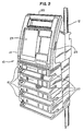
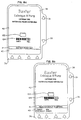
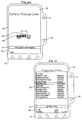
- an intravenous fluid infusion pump made in accordance with the principles of the present invention is referred to generally as 10.
- the pump is clamped onto a standard IV pole 12.
- the pump 10 includes a main body portion 14 and at least one pump module portion 16.
- two pump module portions 16 are provided.
- the present invention contemplates the use of and provides the flexibility to use any number of pumping modules depending on the requirements of the pump user.
- figure 2 shows a pump made in accordance with the principles of the present invention having four pumping modules 16.
- the main body 14 further includes a liquid crystal display (LCD) area 23 which is used to convey various information about the pump 10 to the user and provides for user interface with the pump 10, as described in more detail below.
- the main body 14 includes data-entry keys 25, the use of which are described in detail below.
- the pump module 16 includes a tube-loading channel 27 and an vacuum fluorescent display area 29, also described in detailed below.
- the main body portion 14 includes a slave microprocessor which is a slave to a master microprocessor.
- the slave microprocessor further includes an analog-to-digital converter (A/D converter).
- the master microprocessor is a 80C186 EB available from Intel Corporation, Santa Clara, California
- the slave microprocessor is a 80C552 available from Phillips Semiconductors, Sunnyvale, California. All microprocessors include software in read-only memory (ROM) which drives the user interaction and pump-monitoring functions described below.
- ROM read-only memory
- the present invention provides the flexibility to allow a user to choose a plurality of flow channels depending on the user's requirements.
- the present invention further allows for infusion pumps to be easily modified so that the number of flow channels can be changed.
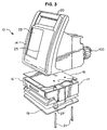
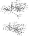
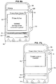
- an infusion pump made in accordance with the principles of the present invention is seen in which a single module is shown in an exploded view, thus depicting the ease by which the pump module is connected to or disconnected from the main body portion.
- the pump module 16 includes module housing 17, an upper module plate 18 and a lower module plate 19. Fastening means are provided to secure the pump module 16 to the main body 14.
- the fastening means include a plurality of extended bolts 21 which extend through apertures defined in the lower module plate 19, the module housing 17 and the upper module plate 18 to threaded apertures defined (not shown) on the bottom of the main body 14. Any number of pump modules 16 can be added to the infusion pump by utilizing the appropriate fastening means.
- the pump module includes a microprocessor.
- the pumpt module microprocessor is a 68HC11 available from Motorola, Schaumburg, Illinois.
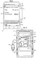
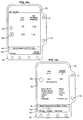
- FIG 4 an elevational view showing the detail of the face of a pump 10 made in accordance with the principles of the present invention is seen.
- a scroll-up arrow key 31 and a scroll-down arrow key 33 are used to select programming fields or actions within the display area.
- a plurality of arrow keys 36 which are used to interact with selection alternatives in the display area 23. Because these arrow keys 36 are used in conjunction with the particular function displayed in the display area 23, as described in detail below, these arrow keys 36 are referred to as "soft keys.”
- the display area 23 includes four display portions. Located at the top portion of the display area is the status display 38.
- the status display 38 gives the status of the pump infusion.
- the status display 38 also identifies alert, alarm, and failure conditions.
- Contained at the lower portion of the display area is the prompt display.
- the prompt display includes a prompt line 41 which provides prompts or instructions for the user.
- a soft key area 40 is further provided which contains labels for the plurality of soft keys 36 located beneath the display area 23.
- the middle portion 42 of the display area 23 is used for making infusion selections, programming, and displaying operating or running conditions of the pump infusion.
- the main body 14 further includes a plurality of function keys 44.
- the function keys 44 include dedicated keys 46 which include user interface keys as well as a numeric key pad 50. Included in the numeric key pad 50 are the numbers zero through nine, and a decimal point key. These numeric and decimal point keys are used to enter programming values into the highlighted field in the display area 23, an example of which is seen in figure 5.
- the numeric key pad 50 further includes a clear key 53 which is used to clear values from the highlighted field. As a safety feature against inadvertent clearing of values from the highlighted field, if the clear key 53 is again pressed after the highlighted field has been cleared, the content of the field is restored to the last value stored in the master microprocessor's memory.
- the dedicated function keys 46 include a main-display function key 55.
- the main-display function key 55 is used to return the display area 23 to the main display from any point in the user interaction.
- the volume-history function key 57 is used to display the volume history screen.
- the silence function key 59 silences pump alarms and pump alerts for a predetermined period, such as two minutes in the preferred embodiment.
- the back-light function key 61 serves one purpose when the pump is plugged into an electrical outlet, and a related but second purpose when the pump is on auxiliary battery power. When plugged into an electrical outlet, the back-light function key 61 turns the display back lights on and off. When on auxiliary battery power, the back-light function key 61 illuminates the display back lights, but in order to conserve power the back lights do not remain on indefinitely.
- the action keys include an on/off charge key 63.
- the on/off charge key 63 powers the infusion pump 10 on and off. When the pump 10 is infusing, pressing the on/off charge key 63 will provide a system override to stop the infusion.
- the action keys further include a start key 65. If all of the required programming values have been collectibly entered during the programming mode, the start key 65 initiates the infusion. Following an alarm notification, once the alarm condition is resolved the start key 65 cancels the alarm notification and restarts the infusion.
- the action keys further include a rate key 68, which is used to select the rate values, and a volume key 70, which is used to select the volume parameters.
- the electronic-plug icon 72 indicates when the infusion pump 10 is plugged into an electrical outlet.
- the electronic-plug icon 72 also indicates that the auxiliary battery is being charged from the electrical power provided by the electrical outlet.
- a battery icon 74 is further provided, which is lit when the pump 10 is operating on auxiliary battery power.
- two additional icons are used.
- a computer control icon indicates when an external computer is transferring data to the pump and a monitor icon indicates when an external computer is querying information from the pump.
- At least one pump module 16 is located beneath the main body 14 of the pump 10. While the pump modules depicted in the preferred embodiment described herein are standard IV tube pump modules, the present invention contemplates use of alternative pump modules employing alternative pumping technology, such as for example, syringe pump modules.
- the pump module 16 includes a tube-loading channel 27 into which a standard IV tube is loaded into the pump 10.
- the pump module 16 includes an automatic tube-loading feature. Contained within the tube-loading channel 27 is a keyed slot 78 adapted to receive a slide clamp contained on the IV tube.
- the pump module 16 includes a free-flow prevention feature.
- the pump module 16 contains several safety features. Initially, the slide clamp 80 is keyed such that it only fits into the keyed slot 78 in the proper orientation. Additionally, beneath the tube-loading channel 27, a fluid flow arrow 81 is provided to instruct the user as to the proper direction of fluid flow in the IV tube. Still further, on the left side of the pump module 16 an intravenous solution bag icon 83 is provided. This reminds the user that the end of the IV tube that connects to the solution bag is to be directed to the left side of the tube-loading channel 27. Still further, on the right side of the pump module 16 is a patient icon 85. This icon 85 is used to remind the user that the end of the IV tube that connects to the patient is to be directed to the right side of the tube-loading channel 27.
- the pump module vacuum fluorescence display area 29 further includes a character display area. In the preferred embodiment depicted herein, an eight-character display area is provided.
- the display area is used to prompt or instruct the user during specific pump interaction operations.
- the display also is used during an alarm or alert condition to identify the particular condition.
- the display is used during infusion to provide an indication of the status of the infusion.
- the character display area Contained beneath the character display area are three light-emitting diode (LED) status indicators.
- the first is a green LED 87 which indicates when the pump is infusing.
- the second is a yellow LED 89 which indicates when the pump is in an alert condition.
- the yellow LED 89 remains continuously lit during an alert condition, provided there are no active alarms.
- the third is a red LED 91 which indicates when the pump is in an alarm condition.
- the red LED 91 flashes on and off during an alarm condition and remains lit continuously during a failure condition. If the infusion pump 10 is running on auxiliary battery power, the alert or alarm display will flash on and off in order to conserve battery power.
- the pump module 16 also includes an open action key 94 and a stop-action key 96.
- the open action key 94 opens the loading mechanism so that an IV tube can be loaded into the tube-loading channel 27.
- the open action key 94 opens the loading mechanism to allow removal of the IV tube.
- the stop-action key 96 provides a system override to stop any active infusion.
- the infusion pump 10 includes a grounded power cord 98 for plugging the pump into a wall outlet to provide standard alternating current (AC) to power the infusion pump 10 and to recharge the auxiliary battery.
- the device further includes a mounting clamp 100 which is used to mount the pump 10 onto an IV pole.
- An audio speaker grill 102 is provided over an audio speaker which is used to generate alert and alarm condition and key press audio tones.
- a communications port 104 is provided to allow the pump 10 to connect and communicate with a computer.
- the communications port 104 also can be used to communicate the nurse call signal to a computer located at a nurse station.
- an RS 232 compatible interface is provided for external communications.
- a direct current (DC) receptacle 107 is further provided.
- the DC receptacle 107 enables the pump 10 to be connected to external DC power sources, such as for example, the 12-volt power source provided in most U.S. vehicles, to enable the pump 10 to be used with an ambulatory patient
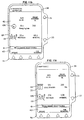
- the rear 97 of the infusion pump 10 further includes fuse compartments 109 which contain electronic fuses as known in the art, an audio speaker volume control 111, and a contrast adjustment 113 for the main display.
- a panel lock button 116 is further provided. Enabling the panel lock button 116 disables many of the front panel keys to prevent inadvertent reprogramming as well as deliberate tampering with the pump.
- each pump module Contained on the side of each pump module is a manual-tube release knob 118.
- This knob 118 provides a manual override of the automatic tube-loading and unloading feature in the pump module 16. This allows the user to manually release the tubing from the pump 10.
- a drop-sensor port 120 Further provided on each pump module is a drop-sensor port 120. This port 120 allows for connection to the pump 10 of an optional drop sensor, which is used in conjunction with a standard drip chamber.
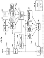
- FIG. 7 a user interface navigation flow diagram is seen. The figure depicts an overview of the user interface routine discussed in detail below.
- the infusion pump performs diagnostic tests while the self-diagnostic routine 300 occurs.
- a power-on screen is displayed.
- the user can access the main display routine 304 or a select set of configuration parameters routine 306. If the select set of configuration parameters routine 306 is selected, the user can access a series of view set of configuration parameters subroutines 308. From the select set of configuration parameters routine 306 or the view set of configuration parameters subroutines 308, the main display routine 304 can be accessed. From the main display routine 304, the user can access a plurality of routines.
- An options menu routine 311 provides access to the view set of configuration parameters series of subroutines 308, a change occlusion settings routine 313, a battery display routine 315 and a configuration/service routine 317. From the options menu routine 311, the series of view set of configuration parameters subroutines 308, the change occlusion settings routine 313 and the battery display routine 315, the main display routine 304 and a configuration/service routine 317 can be accessed.
- the configuration/service routine 317 includes a password entry subroutine which limits access to authorized hospital personnel having a password. Upon input of an authorized password, the authorized hospital personnel can access a configuration/service menu subroutine 319.
- the configuration/service menu subroutine 319 provides access to a device configuration utility subroutine 322, an event history subroutine 324, a service features subroutine 326, and a transfer device configuration subroutine 328. From the device configuration utility subroutine 322, the authorized hospital personnel can access a copy set of configuration parameters subroutine 331 and a series of edit set of configuration parameters subroutines 333. From the service features subroutine 326, the authorized hospital personnel can access a series of service subroutines 335. From the configuration service menu routine 319, the power-on routine 302 can be accessed.
- Further programming routines can be accessed from the main display routine 304. These further programming routines include a primary rate-volume programming routine 339, a primary volume-time programming routine 341, a series of primary dose programming routines 343, a primary ramp programming routine 345, a piggyback rate-volume programming routine 347 and a piggyback volume-time programming routine 349.
- Each of these programming routines provides access to the change mode pop-up window subroutines 352 which provide the ability to switch to other programming routines and to the main display routine.
- the pop-up window subroutines 352 include a prime pop-up subroutine 354 and a standby pop-up subroutine 356.
- the prime pop-up subroutine 354 and the standby pop-up subroutine 356 provide access to the main display routine 304.
- the prime pop-up subroutine 354 can be accessed from each of the programming routines.
- a volume history routine 358 is available from most of the routines.
- the user interaction is principally conducted through the main display area 23, including the scroll-up and scroll-down arrow keys 31, 33 contained on the side and the soft keys 36 displayed underneath the display area.
- the pump self-diagnostic tests begin.
- the main display area 23 initially is lit, then goes dark, while the pump module display 29 illuminates each of the character positions.
- the LEDs are lit and the audible speaker is activated, followed by the sounding of the back-up beeper.
- This procedure enables the user to check for dark spots or lines on the display when the screen is lit, check for light spots or lines on the display when the screen is dark, ensure that the pump module display characters are appropriately lit, ensure that all of the LEDs are in working order, and hear that the audible speaker and back-up buzzer tone are active.
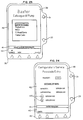
- the screen displays the pump identification screen seen in figure 8(a).
- This screen includes a battery icon 122.
- the battery icon 122 includes a gauge 124 which graphically demonstrates the amount of amp hours remaining in the rechargeable auxiliary battery.
- the prompt line 41 identifies that the pump self-diagnostic tests are proceeding and instructs the user to wait until the self-diagnostic tests are over.
- the prompt line 41 instructs the user that the pump 10 is ready to continue into the programming mode.
- several soft keys are made available, depending on the configuration options chosen by the user. For example, in the embodiment depicted in figure 8(b), a soft key labeled "change Personality”TM is present which enables the user to enter a mode to change the previously selected set of configuration parameters, as described in more detail below.
- a soft key labeled "new patient” is present, indicating that information from a previous program is still retained in the memory. Pressing the "new patient” soft key will clear the programming memory and volume history from this previous patient.
- pressing the main display key 55 advances the display area to the main display screen.
- the user Prior to programming the infusion pump 10, the user is instructed to load an IV tube into the pump module 16. Referring to figure 9, the loading of the IV tube into the automated tube-loading slot in the pump module 16 is described. Initially, the open key 94 is pressed, which causes the automatic tube-loading mechanism to open. As seen in figure 9(a), the user positions the on/off slide clamp 80 into the keyed slot 78, which helps assure the proper orientation of the IV tube. Pulling the IV tube taut, as seen in figure 9(b), the user slides the IV tube into and along the tube-loading channel 27. Once the pump 10 detects the presence of the IV tube, the pump 10 automatically loads the IV tube into the proper position in the pump drive mechanism.
- the automatic tube-loading mechanism will close to assure that an inadvertent loading of an improper IV tube does not occur. Additionally, when off, pressing the open key 94 powers on the infusion pump 10 so that the IV tube can be loaded into the device.
- the main display screen After loading the IV tube, the main display screen returns to the display area, as depicted in figure 8(c).
- the main display screen includes the stop icon 126 which indicates that the pump 10 is not infusing.
- the soft keys 36 include an "option” key, a "primary” key, and a “piggyback” key.
- a stop icon 128 contained above the "primary” soft key indicates the default infusion.
- the display screen prompt instructs the user to press the "primary" soft key or "piggyback" soft key to view the programming mode for those two infusions.
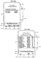
- the rate key 68 is pressed, which changes the display to the rate-volume programming screen with the rate field highlighted, as seen in figure 8(d). If neither the "primary" soft key nor the "piggyback” soft key is pressed, the programming mode assumes the default infusion is to be programmed.
- the rate-volume programming screen prompt line instructs the user to enter the rate or press change mode, while the soft key options include the "change mode” key, the "piggyback" key and label line.
- pressing the clear key 53 clears the incorrect value so that the correct value can be programmed using the numeric key pad 50.
- the start key 65 is pressed. If the programmed values exceed an allowable range preprogrammed into the master microprocessor based on the particular set of configuration parameters chosen by the user, an out-of-range alarm will be activated upon pressing the start key 65.
- the "piggyback" soft key is depressed.
- the stop icon 128 over the piggyback rate-volume programming screen is displayed.
- the rate and volume to be infused in the piggyback is entered in the same manner as the rate and volume information for the primary infusion.
- the piggyback rate-volume programming screen includes the piggyback icon 131, and the display area includes a message informing the user of the primary infusion information.
- the start key is pressed.
- the main display is seen for a single channel with a stopped primary infusion.
- the main display includes the programmed rate of infusion, the volume remaining to be infused, and the time of infusion remaining.
- the main display can further include programmed information about the infusion, such as the total amount of drug, the total volume of diluent, the drug concentration, the weight of the patient and ramp information.
- the soft keys include an "options” soft key, a "primary” soft key and a "piggyback” soft key. Pressing the "primary” soft key or the "piggyback" soft key will display the information for the respective infusion.
- the main display When the infusion pump is operating with a plurality of flow channels, the main display displays configuration parameters for the active channels. For example, referring to figure 11(b) for an infusion pump with a low auxiliary battery condition and two active flow channels, the first flow channel is designated "A" and the second flow channel is designated "B.”
- Flow channel A is a primary infusion which has been stopped because of an air detect, while flow channel B is a labeled, infusing piggyback. All this information plus the designated flow rate and the volume remaining to be infused is depicted in the main display.
- FIG 11(c) a second example is seen with a labeled, paused ramp infusion on flow channel A and a labeled, stopped piggyback on flow channel B.
- a pause icon 135 is displayed for flow channel A.
- the display area When infusing, the display area will show a droplet icon 128 to indicate that the pump 10 is operational.
- the programmed rate of delivery, the volume of fluid remaining to be delivered, and/or the time remaining to deliver the remaining volume will be displayed.
- the stop key is pressed.
- the droplet icon 128 will be replaced with the stop icon 126 on the main display, and the pump LED will no longer be illuminated.
- the start key is pressed.
- the volume remaining and time remaining are not displayed at the same time due to space constraints.
- the volume remaining is displayed for two active channels with channel A running and channel B stopped.
- a "time remaining” soft key is provided which displays the volume remaining.
- a "volume remaining” soft key is provided to toggle to that display.
- a channel stop alert will sound.
- the pump also can be stopped if any alarm condition occurs or if the on/off charge key is pressed while running.
- the piggyback infusion is stopped by closing the on/off clamp on the secondary infusion tube and pressing the stop key.
- the "primary" soft key is pressed to change the operation mode of the pump, followed by the pressing of the start key to begin the primary infusion.
- volume history screen will appear on the display area, and information on the volume infused by the infusion pump, including the date and time the volume was cleared, can be viewed.
- the volume history is retained in the master microprocessor's memory for a predetermined period of time even if the pump is turned off.
- the information includes the date and time the pump volume history was last cleared, the total volume cleared at that time, and the current date and time.
- the prompt line includes instructions on how to clear the volume history.
- the volume history displays the history of the active channels.
- Figure 12 contains an example of volume history for an infusion pump with two active channels.
- a "clear" channel soft key and “done” soft key are provided. If the user desires to clear the volume history, the "clear" channel soft key is pressed. If the user desires to return to the screen from which the volume history screen was accessed, the "done” soft key is pressed. Alternatively, after a predetermined time lapses with no key selection, the pump will automatically return to the screen from which the volume history screen was accessed. If, in the power-on programming mode, the "new patient” soft key is selected or the set of configuration parameters are changed, the volume history will automatically be cleared.
- the infusion pump also provides the ability to change flow rate during an infusion.
- the rate key is pressed. This causes the rate field in the display area to highlight.
- the prompt line instructs the user to enter the new flow rate, and a "rate up” soft key and a “rate down” soft key may be provided.
- the flow rate can be changed by pressing the "rate up” or “rate down” soft keys to increase or decrease the flow rate.
- the numeric key pad can be used to enter a new value into the rate field. After the new rate has been entered into the infusion pump, to begin infusing at the new rate, the start key is pressed.
- the pump will automatically enter a keep-vein-open (KVO) alert mode. During this alert mode, the pump will continue infusing at the lesser of a preprogrammed KVO rate or at the programmed rate. To exit the KVO alert mode, the stop key is pressed. The infusion pump can then be programmed for the next infusion or the pump can be powered off.
- KVO keep-vein-open
- the open key is pressed.
- the pump module automatically closes the slide clamp and opens the tube-loading channel to allow removal of the IV tube.
- the auto load mechanism will close.
- the mechanism will automatically close.
- the IV tube can be removed on an infusion pump that is not powered on. If the open key is pressed while the infusion pump is off, the open key will temporarily power the unit, to allow removal of the IV tube.
- the display area includes a special instruction directing the user to close and remove the slide clamp and the IV tube.
- a manual tube release is provided as a redundant safety feature to allow the IV tube to be unloaded if the loading mechanism becomes disabled.
- the lock function disables all of the front panel keys except the main display, volume history, and back-light key, and the arrow keys as well as the "option,” “primary,” “piggyback,” “channel select” and “select” soft keys for viewing.
- the lock function can only be enabled when the infusion pump is in a standby mode or during an infusion with no alarm or alert conditions present.
- the display area includes a lock icon beneath the prompt line.
- an auto-lock function can be provided which automatically locks the front panel keys after an infusion has been started if no alarms or alerts are present.
- the infusion pump includes several additional user features.
- a pop-up window is seen which displays an options window if the "option" soft key is pressed from the main display.
- the options menu includes a flow check feature, a current PersonalityTM view feature, the selection of the downstream occlusion values, the battery charge level feature, and the configuration/service feature.
- the user highlights the feature to be viewed using the scroll-up and scroll-down arrow keys.
- the current PersonalityTM view feature allows a quick review of the current set of configuration parameters, as described in detail below.
- a display area which includes the flow check display feature.
- the flow check display feature provides the user with a graphical display of the downstream resistance to flow.
- a plurality of triangles 138 are provided which represent the downstream flow resistance. When one triangle 138 is filled, normal flow conditions are present. When all of the triangles 138 are filled, the downstream flow has been occluded. When the downstream flow has been occluded, the occlusion alarm is enabled.
- the downstream occlusion value allows a user to review and change selection of the downstream occlusion levels.
- the options menu will display a downstream occlusion value table, as seen in figure 13(c).
- the prompt line instructs the user how to change the selected values.
- the soft keys include a "no change” soft key, a "PSI/MMHG” soft key, and a "select” soft key.
- the "PSI/MMHG” soft key allows users to view the values in millimeters of mercury instead of the standard pounds per square inch.
- the "select" soft key is pressed on the options menu, the scroll-up and scroll-down arrow keys can be used to highlight the new value range, and the "select” soft key is pressed to lock in the new selection.
- the battery charge level on the options menu allows the user to access information regarding the battery charge level of the auxiliary battery.
- the battery charge icon 122 is displayed in the main display area.
- the prompt line instructs the user how to exit the battery charge level option.
- a "done" soft key is provided to exit the battery charge level display.
- a final selection on the options menu is the configuration/service function.
- This function is made available for hospital service and upkeep personnel for pump configuration selections and for product service. Access to this function requires a pass code entry number, which is intended to be kept by authorized personnel only. This function is described in detail below.
- label line soft key feature
- the label library allows the user to select from a list of informational labels, including solution, therapy and medications identifications. Selection of an informational label displays the selected label on the programming mode screens as well as the main display screen. The selected label also may be displayed on the channel display during infusion. This allows the user to readily identify the solution or medication being infused.
- the user selects the "label line” soft key during the programming mode.
- the "label line” soft key When the "label line” soft key is pressed, a pop-up screen of available labels, including the full name of the medication, therapy or solutions and the label abbreviation, will appear in the display area, an example of which is seen in figure 14.
- the prompt line instructs the user to select a label while "no change,” "page up,” “page down,” and “select” soft keys are provided.
- the “page up” and “page down” soft keys are provided to enable the user to scroll if multiple screens of available labels are used.
- An arrow icon is provided in the lower corner if additional screens of available text are provided.
- An arrow icon is provided in the upper corner (not shown) if previous screens of available text are provided.
- the scroll-up and scroll-down arrow keys are used to highlight the desired label.
- the "select” soft key can then be used to select the label, with the display area automatically reverting back
- the present invention also provides several available programming modes for primary infusion.
- an change mode pop-up menu Upon selection of the "change mode" soft key in the programming mode display, if the programming mode is in the primary programming function, an change mode pop-up menu, as seen in figure 15, is displayed.
- the change mode pop-up menu includes mode and function subroutines.
- the mode subroutine includes the piggyback subroutine previously described, as well as user-selected programming subroutines such as rate/volume, mcg/kg/min, mcg/min, volume/time, and ramp, as described in more detail below.
- the function subroutine includes prime subroutine and standby subroutine.
- the prime subroutine is used to assist users in priming the IV tube in order to ensure that no air is in the IV tube prior to infusion.
- the prime subroutine is accessed by pressing the "change mode" soft key.
- the scroll-up and scroll-down row keys can be employed to highlight the prime field, which can be selected by pressing the "select” soft key.
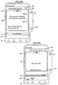
- the display area displays the prime pop-up message, as seen in figure 16(a).
- the prompt line instructs the user to press the "prime” soft key to prime the IV tube.
- a "done” soft key also is provided to indicate when the prime function has been completed. While priming is active, the display area shows the prime pop-up message seen in figure 16(b). Pressing the "done” soft key upon completion of priming returns the display area to the primary infusion program.
- the standby subroutine allows programming of the pump without starting the infusion.
- the standby subroutine disables the channel stop alert notification.
- the scroll-up and scroll-down arrow keys are used to highlight the standby function in the change mode pop-up window.
- the "select" soft key is selected, which causes the standby pop-up message seen in figure 17(a) to appear on the display area. After a brief, predetermined time, the main display screen reappears. However, as seen in figure 17(b), standby is displayed where the program information normally appears. Pressing the "primary" soft key, the "piggyback" soft key, the rate key or the volume key disables the standby function. When disabled, the display returns to the programming routine, based upon which disabling key was selected.
- the optional dose programming subroutines allow the user to program the dose of a primary infusion independent of patient parameters, based on patient body weight or based upon patient body surface area.
- the dose programs which are independent of the patient parameters include mg/hr, mg/min, mcg/min, mcg/hr, units/hr, and units/min.
- Examples of dose programs which are based on patient body weight include mg/kg/hr, mg/kg/min, mcg/kg/hr, mcg/kg/min, units/kg/hr, and units/kg/min.
- Examples of dose programs which are based on patient body surface area include mg/m 2 /hr, mcg/m 2 /hr, and units/m 2 /hr.
- the master microprocessor when two of three parameters have been entered, the master microprocessor will calculate the final parameter. For example, if the dose has been entered and the concentration of the drug has been entered or calculated, as described below, the master microprocessor will calculate and display the rate. Similarly, if the rate has been entered and the concentration of the drug has been entered or calculated, the master microprocessor will calculate and display the dose. After the necessary parameters have been entered and the dose or rate calculated, if the dose or rate values are changed, the master microprocessor will automatically recalculate and display the new values.
- the concentration of the drug to be administered is known by the user, it can be directly input into the infusion pump. If the concentration is not known, the user can enter the drug amount and diluent volume, and the master microprocessor will automatically calculate and display the concentration.
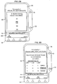
- the programming of the infusion pump is described. From the primary programming modes, the user uses the scroll-up and scroll-down arrow keys on the change mode menu to highlight the appropriate dose formula selection from the examples previously set forth above, an example of which is seen in figure 18(a).
- the prompt line instructs the user to select the programming mode. To select a programming mode, the desired mode is highlighted and the "select" soft key is pressed.
- the display area then displays the dose programming screen seen in figure 18(b).
- the screen will initially display the parameters from that infusion. To clear the displayed parameters, a "clear settings" soft key is pressed.
- the dose programming screen includes a prompt line which instructs the user to enter the amount in the highlighted field. "Change mode,” “label line,” and “units” soft keys we provided.
- the dose programming screen includes the measuring units for each of the categories of dose information. If the user wants to enter different units than those displayed for fields with more than one measuring unit, the "units" soft key is pressed to bring up the unit change list screen, an example of which is seen in figure 18(c).
- the scroll-up and scroll-down arrow keys are used to highlight the desired units, with the select key pressed to change to the desired units.
- the dose programming screen is again displayed. On the dose programming screen, the initial parameter is highlighted for entry by the user.
- the scroll-up and scroll-down arrow keys can be utilized to move the highlighted portion into the desired category. For example, if the concentration is known, the scroll-up and scroll-down arrow keys can be used to highlight the concentration parameter and the concentration can be entered. This eliminates the need to enter the drug amount and diluent volume parameters. If the concentration is not known, the scroll-up and scroll-down arrow keys can be used to highlight and enter the drug amount and diluent volume parameter, with the master microprocessor then calculating and displaying the concentration. The scroll-up and scroll-down arrow keys can then be used to highlight and enter the dose field or to highlight and enter the rate value, with the master microprocessor calculating the unknown parameter.
- the use Prior to starting the infusion, the use must confirm the calculated settings. If the user does not the display area goes to the confirmed settings message window seen in figure 18(d). The prompt line instructs the user to confirm the setting by pressing the "confirm setting" soft key. After the settings have been confirmed, the infusion is started by pressing the start key, as previous described. The display area returns to the main display which, as set forth above, displays the rate, the volume remaining to be infused, and/or the time remaining for the infusion, as well as the dose.
- a similar programming subroutine is utilized. Referring to figure 19, a dose programming screen having parameters related to programming based on the patient's weight is seen.
- the patient's weight must be programmed by entering a value using the numeric key pad. The value can be entered utilizing either kilograms or pounds, with the units selected by using the "units" soft key to highlight the appropriate selected unit.
- a dose programming screen which includes parameters directed to this function.
- the dose programming screen includes the patient's body surface area (BSA) parameter, as seen in figure 20. This BSA parameter is used by the master microprocessor to calculate the dose or rate utilizing a BSA calculation known in the art.
- the pump can be programmed utilizing the volume to be infused and time of infusion parameter, with the master microprocessor calculating the flow rate.
- This feature is available in both the primary and piggyback modes.
- the "change mode" soft key is selected, as seen in figure 21(a).
- a volume/time programming screen is used, having parameters related to programming based on the volume to be infused and the time of infusion.
- values can be entered for the volume to be infused and the time for infusion.
- the pump then automatically calculates and displays the flow rate.
- the "confirm settings" soft key is pressed to confirm the entered values as well as the calculated flow rate, and the start key is pressed.
- the ramp mode allows the user to enter a total volume for infusion and up to four individual time parameters. These time parameters include run time, delay time, ramp-up time, and ramp-down time. Run time includes both the ramp-up and ramp-down time parameters as well as the additional level delivery time. Delay time is the time prior to ramp-up, when the device runs at a preselected KVO rate. Ramp-up time is the time established for the device to ramp up to the level delivery rate. Ramp-down is the time established for the device to ramp down from the level delivery rate to the KVO rate.
- the master microprocessor calculates the rates necessary to perform the time and volume requirements.
- the total volume includes the volume infused during the ramp-up, level delivery, and ramp-down times as well as the volume delivered during the KVO delay time.
- volume delivered during the ramp-up, level delivery, and ramp-down times is calculated based on the total volume to be infused less the volume delivered during delay time.
- the ramp programming screen includes the total volume, run time, delay time, ramp-up time, and ramp-down time. These parameters can be entered utilizing the scroll-up and scroll-down arrow keys to highlight the appropriate field.
- the pump will calculate the level delivery rate.
- the level delivery rate will be displayed above a ramp delivery icon 140.
- the "confirm settings" soft key confirms the entered values as well as the calculated level delivery rate. To begin infusing, the start key is pressed.
- the main display also includes the ramp status icon 142.
- the ramp status icon 142 includes a likeness of the stages of the ramp infusion, including the delay time 144, the ramp-up 146, the level delivery 148, and the ramp-down 150 periods.
- the ramp status icon 142 is continually updated to show the progression of the therapy. The portion of the ramp infusion that is completed is shown shaded in black.
- the prompt line includes the user instructions to view the settings for the ramp infusion.
- a ramp infusion parameter screen shows the entered parameters for the ramp infusion.
- a ramp-in-progress screen which includes the rate, volume, and time as well as the ramp status icon 142, is displayed, as seen in figure 22(c).
- the prompt line in the display area includes options available to the user depending upon the status of the ramp infusion. In the example of the status depicted in figure 22(c), during level delivery the option available to the user is to immediately ramp down. Thus, a "ramp down" soft key is provided.
- the drop sensor is connected to the drop sensor connector.
- the drop sensor is attached to the drip chamber above the fluid level on the IV tube connected to the primary source fluid container.
- a container-empty alert will occur and the device will infuse at the KVO rate during the alert.
- a container empty alarm will follow the container empty alert.
- the primary-volume-to-be-infused field is not mandatory. If the primary-volume-to-be-infused field is not entered, the infusion pump will operate at the program rate until the drop sensor detects an empty fluid container.
- the pump is capable of functioning in a variety of clinical uses from basic through advanced programming functions.
- the present invention includes a variety of configurable sets of configuration parameters.
- the "change personalities" soft key from the power-on screen is pressed.
- examples of custom sets of configuration parameters such as the general floor, pediatrics, neonatal intensive care (NICU), critical care (ICU), and home care are listed.
- the scroll-up and scroll-down arrow keys highlight the chosen set of configuration parameters.
- the "view" soft key is pressed to display a PersonalityTM configuration screen.
- the "select" soft key is pressed.
- the configuration/service function of the options menu seen in figure 13(a) is selected.
- a password entry screen seen in figure 24 appears.
- the password ensures that only proper hospital personnel access the configuration/service routine.
- the prompt line directs entry of the password.
- the authorized personnel enter a numeral password in order to proceed in the configuration/service routine.
- the password entry screen includes a reference listing of the software version in the infusion pump. A "cancel" soft key is provided to exit the routine.
- a configuration/service menu screen as seen in figure 25(a) appears.
- the options include PersonalityTM configuration utility, device configuration utility, event history, service features, device configuration transfer, download configuration, time set and date set
- the device configuration transfer allows the authorized hospital personnel to transfer the configuration of one infusion pump to another infusion pump.
- the download configuration allows the authorized hospital personnel to download the infusion pump configuration through the serial port.
- the configuration service menu includes a "select" soft key and a "done” soft key. When an option is highlighted, a message appears giving the particular components of an option.
- the PersonalityTM configuration utility includes as components a PersonalityTM list, infusion modes and features, infusion limit alerts and alarms, drop sensors, and label library.
- a PersonalityTM list is displayed as seen in figure 25(b).
- the power-on default set of configuration parameters is identified in the display. "Done,” “up” and “down” soft keys appear.
- a "change settings” soft key, an "enable/disable” soft key, and a "copy PersonalityTM” soft key appear.
- the authorized hospital personnel can modify or view the set of configuration parameters by using the "change settings” soft key, modify the name of the set of configuration parameters by using the "change settings” soft key, copy the configuration of the set of configuration parameters by selecting the "copy PersonalityTM” soft key, or enable or disable the set of configuration parameters by using the "enable/disable” soft key.
- a set of configuration parameters is enabled, it will appear listed in the list of sets of configuration parameters when the "new PersonalityTM" soft key is pressed after power-on.
- a PersonalityTM configuration menu for the selected set of configuration parameters is displayed, an example of which is seen in figure 25(c).
- the PersonalityTM configuration menu identifies the components.
- a message identifies the configurable items found in the highlighted component.
- the soft keys include a "done” soft key, a "select” soft key, and a "PersonalityTM name” soft key. Selection of the "PersonalityTM name” soft key displays the create name screen seen in figure 25(d). Using the soft keys and the scroll-up and scroll-down arrow keys, authorized hospital personnel can enter the name of a set of configuration parameters.
- Selection of the infusion mode and features allows the authorized hospital personnel to determine which features and functions will be available for the clinical user for that set of configuration parameters and how the infusion pump will display features and functions to the clinical user. Examples include disable infusion modes, disable dose formulae, set channel display, disable piggyback mode, disable prime mode, enable quick titration, and enable flow check display.
- the authorized hospital personnel can enable or disable the label library.
- the authorized hospital personnel also can select which medication or solution names are available to the clinical user for selection if the label library is enabled.
- "done,” "library set up” and “enable/disable” soft keys are provided.
- the label library set-up list is displayed, as seen in figure 26(b).
- a "yes/no" soft key is provided to enable or disable labels.
- the present invention also provides several troubleshooting alert, alarm and failure messages.
- alert messages may require a user intervention, but do not stop the infusion.
- Alarm conditions automatically stop the infusion and require immediate attention before infusion can be restarted.
- a device failure automatically stops any infusion.
- An alarm condition overrides an existing alert condition while a failure overrides all alerts and alarms.
- An alert condition lights the yellow alert LED beneath the pump module display, and sounds the alert tone.
- the alert tone can be silenced for a period of time, such as for example two minutes, by pressing the silence key.
- the alert conditions include advanced air alert which indicates that the user is advancing a detected air bubble.
- a battery-low alert indicates that the auxiliary battery has less than a predetermined amount of infusion time left. This alert occurs before the battery alarm condition, discussed below, occurs.
- the changing piggyback alert indicates that the piggyback rate is being changed or a label is being added.
- the changing primary alert indicates that a primary rate or dose is being changed or label is being added during an infusion.
- the channel-stopped alert indicates that the pump is on, not in standby mode, but the infusion is not running. This alert is designed to remind the user to start the pump infusion or to power-off the pump.
- the container-empty alert indicates that the drop sensor accessory has sensed that the source container is empty and the device is infusing at the lower of the KVO rate or the preprogrammed rate.
- the KVO alert indicates that the programmed volume to be infused has been completed.
- the piggyback-callback alert indicates that the piggyback infusion has been completed and the pump has switched to the primary infusion. To continue primary infusion, the silence key can be pressed.
- the prime alert indicates that the priming module is being employed.
- the programming-piggyback alert indicates that a piggyback infusion is being programmed while a primary infusion is taking place. This alert is intended as a reminder to the user to complete the piggyback program and start the piggyback infusion, if appropriate.
- the ramp-paused alert indicates that a ramp infusion has been paused. This reminds the user to press the start key to resume the ramp or to press the "cancel ramp” soft key to cancel the infusion.
- the air-detect alarm indicates that an air bubble has been detected based on preprogrammed air bubble detection parameters.
- the display area displays the air-in-line icon 153 and the user is asked if the advance air feature is desired to be used to view the air bubble, as seen in figure 27(a). Choosing the advance air feature advances the display screen to the "advance air screen depicted in figure 27(b). To advance the air bubble, the user presses and holds the "advance air” soft key. When the air-detect feature again, detects fluid, the display area will inform the user of the fluid detection by displaying the fluid icon 155, seen in figure 27(c).
- the user can continue to advance the air bubble until it is at the injection site on the tubing, where it can be removed using a syringe.
- the alarm condition has been reset and the infusion can be restarted by pressing the start key.
- a user can advance air until a maximum defined volume has been pumped. Once this maximum volume has been pumped, the display informs the clinical user, as seen in figure 27(d). The IV tube should be removed and manually purged to reset the alarm.
- the battery-depleted alarm indicates that the auxiliary battery charge has diminished below the level necessary to continue infusion.
- the pump To reset this alarm, the pump must be plugged into an AC supply.
- the check-drop-sensor alarm indicates that, if the pump has been configured for mandatory drop sensor use, the sensor has not been connected. To reset this alarm, the drop sensor must be connected.
- the downstream-occlusion alarm indicates that a downstream occlusion, such as a closed distal flow clamp, has occurred. To reset this alarm, the downstream occlusion must be removed. If the pump is configured with the auto restart feature, the pump will automatically restart if the occlusion has been removed within a predetermined period of time after occlusion detection.
- the drop sensor malfunction alarm indicates that the drop sensor either has been improperly positioned on the drip chamber in the IV tube or has been damaged. To reset this alarm, the drop sensor must be properly positioned or repaired if damaged.
- the flow-detected-on-primary alarm indicates that the drop sensor has detected drops in the primary drip chamber when the piggyback should be infusing. To reset this alarm, the problem causing the flow from the primary fluid source, such as the piggyback infusion source being located at or lower than the level of the primary fluid source or the inadvertent closure of the slide clamp on the IV tube connected to the piggyback fluid source, must be removed.
- the incomplete-program alarm indicates that the start key was pressed prior to entering or confirming a programming parameter. To reset this alarm, the missing parameter value and the "confirm settings" soft key, if required, must be entered.
- the reset-manual-release alarm indicates that the manual tube release has been activated. To reset this alarm, the manual tube release must be reset.
- the tube-not-loaded alarm indicates that the IV tube has not been loaded prior to pressing the start key. To reset this alarm, the IV tube must be loaded.
- the out-of-range alarm indicates that a programming value outside of the preprogrammed allowable range has been entered. This alarm occurs when the "confirm settings" soft key or start key is pressed. To reset the out-of-range alarm, values within the preprogrammed range must be entered.
- the temperature-too-high alarm indicates that the operating temperature of the tube is outside design limits. To reset this alarm, the tube must be cooled by moving the pump to a suitable temperature environment.
- the temperature-too-low alarm means that the operating temperature of the tube is outside the design limits. To remove this alarm, the tube must be warmed by moving the pump to a suitable temperature environment.
- the tube-misload alarm indicates that the IV tube has been improperly loaded. To remove this alarm, the IV tube must be removed and reloaded properly.
- the tube-unload alarm indicates that the IV tube has not been removed from the tube-loading channel during an attempted tube-unloading procedure. If this occurs, the proper tube-unloading procedure should be employed or the manual tube release should be used.
- the upstream-occlusion alarm indicates that an upstream occlusion, such as a closed proximal slide clamp, has occurred. To reset this alarm, the source of the occlusion must be removed.
- the container-empty alarm follows the container-empty alert condition described above. This alarm indicates that the container-empty alert condition has existed for a predetermined volume. To reset this alarm, a new fluid source container must be connected or the pump powered off.
- the no-slide-clamp alarm indicates that the on/off slide clamp has not been properly loaded. To reset this alarm, the tubing must be removed and reloaded, properly locating the on/off slide clamp in the keyed slot.
- the authorized hospital personnel can program clinical feature limits and infusion alert and alarm characteristics.
- the infusion limits, alerts and alarms are accessed from the PersonalityTM configuration menu, seen in figure 28(a).
- the infusion limits, alerts and alarms menu seen in figure 28(b) is displayed.
- the settings in this menu apply to the infusion pump as a whole and are not programmable for separate channels.
- the authorized hospital personnel can adjust the flow rate limit, adjust the maximum volume to be infused, adjust the KVO rate, enable or disable a piggyback callback alert, adjust the time between audible tones for the alert and alarm, and enable or disable the auto-lock feature.
- the authorized hospital personnel also can set the size of the air bubble to be detected by the infusion pump. Referring to figure 29, an air bubble select pull-down menu which is displayed upon selection of the air bubble setting is seen.
- the screen includes a "no change" soft key and a "select" soft key.
- Options on the bubble size are displayed.
- four bubble size levels are displayed. In the preferred embodiment described herein, the four bubble size levels are 25 microL, 50 microL, 100 microL and 150 microL.
- Each bubble size level will detect air bubbles within a given range. For example, the 25 microL level will detect air bubbles above 25 microL and will not detect air bubbles below 10 microL; the 50 microL level will detect air bubbles above 50 microL and will not detect air bubbles below 25 microL; the 100 microL level will detect air bubbles above 100 microL and will not detect air bubbles below 50 microL; and the 150 microL level will detect air bubbles above 150 microL and will not detect air bubbles below 100 microL.
- the authorized hospital personnel also can select a range of downstream occlusion values to be detected by the infusion pump.
- a downstream occlusion value pull-down menu which is displayed upon selection of the downstream occlusion values, is seen.
- the screen includes a "no change" soft key, a "PSI/MMHG” soft key which selects the units, and a "select” soft key.
- Options on the downstream occlusion values are displayed.
- three downstream occlusion values are displayed.
- the three values are minimum, moderate and maximum. The minimum, moderate and maximum values indicate an approximate maximum pressure for different flow rate ranges.
- three flow rate ranges are indicated.
- the authorized hospital personnel also can set whether the clinician can override the downstream occlusion values.
- the occlusion value clinician override is highlighted in the infusion limits, alerts and alarm menu, an "enable/disable" soft key appears.
- the infusion pump also can be configured to include an auto-restart function. This function enables the infusion pump to automatically restart itself when a downstream occlusion has been corrected within a predetermined time, such as in the preferred embodiment, within one minute after detection. This is likely to occur if, for example, the downstream occlusion is caused by patient movement which subsequently opens the IV tube. The infusion pump will continue to attempt an auto restart for a given number of preselected occurrences before manual intervention is required.
- the authorized hospital personnel also can set the number of auto restarts that will occur after a downstream occlusion alarm occurs and is relieved.
- the authorized hospital personnel also can require that a clinician program a fluid delivery so that the fluid level in the drip chamber, in conjunction with a drop sensor, can provide a container-empty alert.
- a clinician program a fluid delivery so that the fluid level in the drip chamber, in conjunction with a drop sensor, can provide a container-empty alert.
- the infusion pump further includes service features which are accessible from the configuration/service menu. Upon selection of the service features, a service features menu is displayed. In the battery information selection, the slave microprocessor keeps track of a plurality of time periods related to battery operation. In the preferred embodiment, several parameters are tracked, including the total amount of time the infusion pump is on and not plugged in, the total amount of time the infusion pump was on.
- a battery information screen includes the battery charge icon 122, "done" and "clear times" soft keys, and the parameters. When a new battery is installed, the time on battery parameter is cleared.
- the service features also include sensor calibration, which displays information related to the installation or replacement of certain infusion pump components, and manufacturing tests, which are used in the manufacturing process to calibrate infusion pump components.
Abstract
Description
- The present invention relates to medical infusion pumps in general and in particular to user interfaces for medical infusion pumps.
- The administration of intravenous medical fluids to a patient is well known in the art. Typically, a solution such as saline, glucose or electrolyte contained in a glass or flexible container is fed into a patient's venous system through a conduit such as a polyvinyl chloride (PVC) intravenous (IV) tube which is accessed to the patient by a catheter. Many times, the fluid is infused under the forces of gravity, and the rate of flow is controlled by a roller clamp which is adjusted to restrict the flow lumen of the IV tube until the desired flow rate is obtained.
- Flow from the container to the patient also is known to be regulated by means other than a roller clamp. It is becoming more and more common to use an electronically controlled infusion pump. Such pumps include, for example, peristaltic-type pumps and valve-type pumps. Peristaltic-type pumps typically include an array of cams angularly spaced from each other which drive cam followers connected to pressure fingers. These elements cooperate to impart a linear wave motion on the pressure fingers. This linear wave motion is used to apply force to the IV tube, which imparts the motion to the fluid in the IV tube thereby propelling the fluid. An alternative type of peristaltic pump employs a plurality of roller members which roll over the IV tube to impart the motion to the fluid in the IV tube. Infusion pumps also employ pumping chambers having upstream and downstream valves to sequentially impart the propulsion to the fluid. Such valve-type pumps typically require the use of a specialized pumping cassette chamber, which is contained on a dedicated IV tube between the patient and the source of fluid.
- Infusion pumps of the prior art are typically designed for a particular clinical application. For example, many pumps are designed principally for use as general floor pumps in hospital facilities. Other pumps are designed particularly for pediatric use. Other pumps are designed for critical care use. Still other pumps are principally designed for home care use. This specialized pumping use requires hospitals and health care facilities to employ a large inventory of such devices, which increases the capital investment and cost of such hospital care.
- Further, it is often required that a single patient be simultaneously infused with a number of medical fluids. Most pumps employ a single flow channel, which adds to the expense and crowds the space surrounding a patient when such multiple infusions are required. Although pumps exist which employ dual channels, use of such pumps when only a single intravenous fluid is required to be infused in the patient results in unused capacity and the inability to transfer such unused capacity to other patients.
- What is needed is a medical infusion pump which is readily adaptable to use in multiple clinical settings without unduly burdening the user with programming parameters for such a variety of uses. It would be further advantageous for a pump to allow the user to select the number of flow channels available or to allow for existing pumps to add flow channels as needed.
- The present invention provides a medical infusion pump which is readily adaptable to use m multiple clinical settings without unduly burdening the user with programming parameters for such a variety of uses. The present invention provides a pump which allows the user to select the number of flow channels available or to allow for existing pumps to add flow channels as needed.
- The present invention provides an infusion pump having a main body portion. The main body portion includes a display area for displaying user interface information. At least one pump module is provided which is removably secured to the main body portion and adapted to receive an IV tube. The pump module includes means for applying pumping action to the IV tube. The pump module further includes an auxiliary display area for displaying supplemental user interface information. A microprocessor is contained in the main body portion for generating user interface information on the display areas.
-
- Figure 1 is a perspective view of an infusion pump constructed in accordance with the principles of the present invention;
- Figure 2 is a perspective view of an alternative embodiment of an infusion pump constructed in accordance with the principles of the present invention;
- Figure 3 is an exploded view of an alternative embodiment of an infusion pump constructed in accordance with the principles of the present invention;
- Figure 4 is an elevational view of the infusion pump of figure 1, showing the detail of the pump face;
- Figure 5 is a detailed view of the display area of the infusion pumps of figures 1 and 2;
- Figure 6 is an elevational view of the rear of the infusion pump of figure 1;
- Figure 7 is a user interface navigation flow diagram constructed in accordance with the principles of the present invention; and
- Figures 8 to 30 shows the details of the user interaction with a pump constructed in accordance with the principles of the present invention.
-
- Referring to figure 1, an intravenous fluid infusion pump made in accordance with the principles of the present invention is referred to generally as 10. The pump is clamped onto a standard IV
pole 12. Thepump 10 includes amain body portion 14 and at least onepump module portion 16. In the embodiment depicted and described herein, twopump module portions 16 are provided. However, the present invention contemplates the use of and provides the flexibility to use any number of pumping modules depending on the requirements of the pump user. For example, figure 2 shows a pump made in accordance with the principles of the present invention having fourpumping modules 16. - Formed at the upper periphery of the
main body portion 14 is acarrying handle 20. Themain body 14 further includes a liquid crystal display (LCD)area 23 which is used to convey various information about thepump 10 to the user and provides for user interface with thepump 10, as described in more detail below. Themain body 14 includes data-entry keys 25, the use of which are described in detail below. Thepump module 16 includes a tube-loading channel 27 and an vacuumfluorescent display area 29, also described in detailed below. Themain body portion 14 includes a slave microprocessor which is a slave to a master microprocessor. The slave microprocessor further includes an analog-to-digital converter (A/D converter). In a preferred embodiment, the master microprocessor is a 80C186 EB available from Intel Corporation, Santa Clara, California, and the slave microprocessor is a 80C552 available from Phillips Semiconductors, Sunnyvale, California. All microprocessors include software in read-only memory (ROM) which drives the user interaction and pump-monitoring functions described below. - It is a particular advantage that the present invention provides the flexibility to allow a user to choose a plurality of flow channels depending on the user's requirements. The present invention further allows for infusion pumps to be easily modified so that the number of flow channels can be changed. Referring now to figure 3, an infusion pump made in accordance with the principles of the present invention is seen in which a single module is shown in an exploded view, thus depicting the ease by which the pump module is connected to or disconnected from the main body portion.
- The
pump module 16 includesmodule housing 17, anupper module plate 18 and alower module plate 19. Fastening means are provided to secure thepump module 16 to themain body 14. The fastening means include a plurality of extendedbolts 21 which extend through apertures defined in thelower module plate 19, themodule housing 17 and theupper module plate 18 to threaded apertures defined (not shown) on the bottom of themain body 14. Any number ofpump modules 16 can be added to the infusion pump by utilizing the appropriate fastening means. The pump module includes a microprocessor. In a preferred embodiment, the pumpt module microprocessor is a 68HC11 available from Motorola, Schaumburg, Illinois. - Referring to figure 4, an elevational view showing the detail of the face of a
pump 10 made in accordance with the principles of the present invention is seen. Contained along the side of thedisplay area 23 are a scroll-uparrow key 31 and a scroll-downarrow key 33. These keys are used to select programming fields or actions within the display area. Contained beneath thedisplay area 23 are a plurality ofarrow keys 36 which are used to interact with selection alternatives in thedisplay area 23. Because thesearrow keys 36 are used in conjunction with the particular function displayed in thedisplay area 23, as described in detail below, thesearrow keys 36 are referred to as "soft keys." - Referring now to figure 5, an example of the
display area 23 of the infusion pump is seen. Thedisplay area 23 includes four display portions. Located at the top portion of the display area is thestatus display 38. Thestatus display 38 gives the status of the pump infusion. Thestatus display 38 also identifies alert, alarm, and failure conditions. Contained at the lower portion of the display area is the prompt display. The prompt display includes aprompt line 41 which provides prompts or instructions for the user. Asoft key area 40 is further provided which contains labels for the plurality ofsoft keys 36 located beneath thedisplay area 23. Thus, by following the prompts and making selections in accordance with the labels applied to thesoft keys 36, the user can interface with thedisplay area 23. Finally, themiddle portion 42 of thedisplay area 23 is used for making infusion selections, programming, and displaying operating or running conditions of the pump infusion. - Referring back to figure 4, the
main body 14 further includes a plurality offunction keys 44. Thefunction keys 44 includededicated keys 46 which include user interface keys as well as a numerickey pad 50. Included in the numerickey pad 50 are the numbers zero through nine, and a decimal point key. These numeric and decimal point keys are used to enter programming values into the highlighted field in thedisplay area 23, an example of which is seen in figure 5. The numerickey pad 50 further includes aclear key 53 which is used to clear values from the highlighted field. As a safety feature against inadvertent clearing of values from the highlighted field, if theclear key 53 is again pressed after the highlighted field has been cleared, the content of the field is restored to the last value stored in the master microprocessor's memory. - The
dedicated function keys 46 include a main-display function key 55. The main-display function key 55 is used to return thedisplay area 23 to the main display from any point in the user interaction. The volume-history function key 57 is used to display the volume history screen. Thesilence function key 59 silences pump alarms and pump alerts for a predetermined period, such as two minutes in the preferred embodiment. The back-light function key 61 serves one purpose when the pump is plugged into an electrical outlet, and a related but second purpose when the pump is on auxiliary battery power. When plugged into an electrical outlet, the back-light function key 61 turns the display back lights on and off. When on auxiliary battery power, the back-light function key 61 illuminates the display back lights, but in order to conserve power the back lights do not remain on indefinitely. - Included in the action keys is an on/off
charge key 63. The on/off charge key 63 powers theinfusion pump 10 on and off. When thepump 10 is infusing, pressing the on/offcharge key 63 will provide a system override to stop the infusion. The action keys further include astart key 65. If all of the required programming values have been collectibly entered during the programming mode, thestart key 65 initiates the infusion. Following an alarm notification, once the alarm condition is resolved thestart key 65 cancels the alarm notification and restarts the infusion. The action keys further include arate key 68, which is used to select the rate values, and avolume key 70, which is used to select the volume parameters. - Two additional icons are used as indicators of pump conditions. The electronic-
plug icon 72 indicates when theinfusion pump 10 is plugged into an electrical outlet. The electronic-plug icon 72 also indicates that the auxiliary battery is being charged from the electrical power provided by the electrical outlet. Abattery icon 74 is further provided, which is lit when thepump 10 is operating on auxiliary battery power. In an additional embodiment, two additional icons are used. A computer control icon indicates when an external computer is transferring data to the pump and a monitor icon indicates when an external computer is querying information from the pump. - At least one
pump module 16 is located beneath themain body 14 of thepump 10. While the pump modules depicted in the preferred embodiment described herein are standard IV tube pump modules, the present invention contemplates use of alternative pump modules employing alternative pumping technology, such as for example, syringe pump modules. Thepump module 16 includes a tube-loading channel 27 into which a standard IV tube is loaded into thepump 10. Thepump module 16 includes an automatic tube-loading feature. Contained within the tube-loading channel 27 is akeyed slot 78 adapted to receive a slide clamp contained on the IV tube. Thepump module 16 includes a free-flow prevention feature. - In order to assure that the IV tube is loaded into the
pump module 16 in the proper orientation, thepump module 16 contains several safety features. Initially, theslide clamp 80 is keyed such that it only fits into the keyedslot 78 in the proper orientation. Additionally, beneath the tube-loading channel 27, afluid flow arrow 81 is provided to instruct the user as to the proper direction of fluid flow in the IV tube. Still further, on the left side of thepump module 16 an intravenoussolution bag icon 83 is provided. This reminds the user that the end of the IV tube that connects to the solution bag is to be directed to the left side of the tube-loading channel 27. Still further, on the right side of thepump module 16 is apatient icon 85. Thisicon 85 is used to remind the user that the end of the IV tube that connects to the patient is to be directed to the right side of the tube-loading channel 27. - The pump module vacuum
fluorescence display area 29 further includes a character display area. In the preferred embodiment depicted herein, an eight-character display area is provided. The display area is used to prompt or instruct the user during specific pump interaction operations. The display also is used during an alarm or alert condition to identify the particular condition. Finally, the display is used during infusion to provide an indication of the status of the infusion. - Contained beneath the character display area are three light-emitting diode (LED) status indicators. The first is a
green LED 87 which indicates when the pump is infusing. The second is ayellow LED 89 which indicates when the pump is in an alert condition. Theyellow LED 89 remains continuously lit during an alert condition, provided there are no active alarms. The third is ared LED 91 which indicates when the pump is in an alarm condition. Thered LED 91 flashes on and off during an alarm condition and remains lit continuously during a failure condition. If theinfusion pump 10 is running on auxiliary battery power, the alert or alarm display will flash on and off in order to conserve battery power. - The
pump module 16 also includes an open action key 94 and a stop-action key 96. The open action key 94 opens the loading mechanism so that an IV tube can be loaded into the tube-loading channel 27. When an IV tube is contained in thepump module 16, the open action key 94 opens the loading mechanism to allow removal of the IV tube. The stop-action key 96 provides a system override to stop any active infusion. - Referring now to figure 6, the rear 97 of the
infusion pump 10 is seen. Theinfusion pump 10 includes a groundedpower cord 98 for plugging the pump into a wall outlet to provide standard alternating current (AC) to power theinfusion pump 10 and to recharge the auxiliary battery. The device further includes a mountingclamp 100 which is used to mount thepump 10 onto an IV pole. Anaudio speaker grill 102 is provided over an audio speaker which is used to generate alert and alarm condition and key press audio tones. Acommunications port 104 is provided to allow thepump 10 to connect and communicate with a computer. Thecommunications port 104 also can be used to communicate the nurse call signal to a computer located at a nurse station. In the preferred embodiment, an RS 232 compatible interface is provided for external communications. - A direct current (DC) receptacle 107 is further provided. The
DC receptacle 107 enables thepump 10 to be connected to external DC power sources, such as for example, the 12-volt power source provided in most U.S. vehicles, to enable thepump 10 to be used with an ambulatory patient The rear 97 of theinfusion pump 10 further includes fuse compartments 109 which contain electronic fuses as known in the art, an audiospeaker volume control 111, and acontrast adjustment 113 for the main display. Further provided is apanel lock button 116. Enabling thepanel lock button 116 disables many of the front panel keys to prevent inadvertent reprogramming as well as deliberate tampering with the pump. - Contained on the side of each pump module is a manual-
tube release knob 118. Thisknob 118 provides a manual override of the automatic tube-loading and unloading feature in thepump module 16. This allows the user to manually release the tubing from thepump 10. Further provided on each pump module is a drop-sensor port 120. Thisport 120 allows for connection to thepump 10 of an optional drop sensor, which is used in conjunction with a standard drip chamber. - Referring now to figure 7, a user interface navigation flow diagram is seen. The figure depicts an overview of the user interface routine discussed in detail below. Upon power-up, the infusion pump performs diagnostic tests while the self-
diagnostic routine 300 occurs. After completion of the diagnostic tests, a power-on screen is displayed. From the power-onroutine 302, the user can access themain display routine 304 or a select set of configuration parameters routine 306. If the select set of configuration parameters routine 306 is selected, the user can access a series of view set of configuration parameters subroutines 308. From the select set of configuration parameters routine 306 or the view set ofconfiguration parameters subroutines 308, themain display routine 304 can be accessed. From themain display routine 304, the user can access a plurality of routines. Anoptions menu routine 311 provides access to the view set of configuration parameters series ofsubroutines 308, a change occlusion settings routine 313, abattery display routine 315 and a configuration/service routine 317. From theoptions menu routine 311, the series of view set ofconfiguration parameters subroutines 308, the change occlusion settings routine 313 and thebattery display routine 315, themain display routine 304 and a configuration/service routine 317 can be accessed. - The configuration/
service routine 317 includes a password entry subroutine which limits access to authorized hospital personnel having a password. Upon input of an authorized password, the authorized hospital personnel can access a configuration/service menu subroutine 319. The configuration/service menu subroutine 319 provides access to a deviceconfiguration utility subroutine 322, anevent history subroutine 324, a service featuressubroutine 326, and a transferdevice configuration subroutine 328. From the deviceconfiguration utility subroutine 322, the authorized hospital personnel can access a copy set ofconfiguration parameters subroutine 331 and a series of edit set of configuration parameters subroutines 333. From the service featuressubroutine 326, the authorized hospital personnel can access a series ofservice subroutines 335. From the configurationservice menu routine 319, the power-on routine 302 can be accessed. - Further programming routines can be accessed from the
main display routine 304. These further programming routines include a primary rate-volume programming routine 339, a primary volume-time programming routine 341, a series of primarydose programming routines 343, a primaryramp programming routine 345, a piggyback rate-volume programming routine 347 and a piggyback volume-time programming routine 349. - Each of these programming routines provides access to the change mode pop-up
window subroutines 352 which provide the ability to switch to other programming routines and to the main display routine. The pop-upwindow subroutines 352 include a prime pop-upsubroutine 354 and a standby pop-upsubroutine 356. The prime pop-upsubroutine 354 and the standby pop-upsubroutine 356 provide access to themain display routine 304. The prime pop-upsubroutine 354 can be accessed from each of the programming routines. Avolume history routine 358 is available from most of the routines. - Referring now to figures 8 to 30, the user interaction with the
infusion pump 10 is described in detail. As previously discussed, the user interaction is principally conducted through themain display area 23, including the scroll-up and scroll-downarrow keys soft keys 36 displayed underneath the display area. - Upon power-up of the
pump 10 by pressing the on/offcharge key 63, the pump self-diagnostic tests begin. Themain display area 23 initially is lit, then goes dark, while thepump module display 29 illuminates each of the character positions. Next, the LEDs are lit and the audible speaker is activated, followed by the sounding of the back-up beeper. This procedure enables the user to check for dark spots or lines on the display when the screen is lit, check for light spots or lines on the display when the screen is dark, ensure that the pump module display characters are appropriately lit, ensure that all of the LEDs are in working order, and hear that the audible speaker and back-up buzzer tone are active. - Once the display area, LED, and speaker tests are complete, the screen displays the pump identification screen seen in figure 8(a). This screen includes a
battery icon 122. Thebattery icon 122 includes agauge 124 which graphically demonstrates the amount of amp hours remaining in the rechargeable auxiliary battery. In this initial screen, theprompt line 41 identifies that the pump self-diagnostic tests are proceeding and instructs the user to wait until the self-diagnostic tests are over. - Referring now to figure 8(b), after the self-diagnostic tests are completed, the
prompt line 41 instructs the user that thepump 10 is ready to continue into the programming mode. Additionally, several soft keys are made available, depending on the configuration options chosen by the user. For example, in the embodiment depicted in figure 8(b), a soft key labeled "change Personality"™ is present which enables the user to enter a mode to change the previously selected set of configuration parameters, as described in more detail below. Additionally, a soft key labeled "new patient" is present, indicating that information from a previous program is still retained in the memory. Pressing the "new patient" soft key will clear the programming memory and volume history from this previous patient. As instructed in theprompt line 41, pressing the main display key 55 advances the display area to the main display screen. - Prior to programming the
infusion pump 10, the user is instructed to load an IV tube into thepump module 16. Referring to figure 9, the loading of the IV tube into the automated tube-loading slot in thepump module 16 is described. Initially, the open key 94 is pressed, which causes the automatic tube-loading mechanism to open. As seen in figure 9(a), the user positions the on/offslide clamp 80 into the keyedslot 78, which helps assure the proper orientation of the IV tube. Pulling the IV tube taut, as seen in figure 9(b), the user slides the IV tube into and along the tube-loading channel 27. Once thepump 10 detects the presence of the IV tube, thepump 10 automatically loads the IV tube into the proper position in the pump drive mechanism. If the IV tube is not loaded in a given predetermined time period, 30 seconds in the preferred embodiment, after the open key 94 has been pressed, the automatic tube-loading mechanism will close to assure that an inadvertent loading of an improper IV tube does not occur. Additionally, when off, pressing the open key 94 powers on theinfusion pump 10 so that the IV tube can be loaded into the device. - After loading the IV tube, the main display screen returns to the display area, as depicted in figure 8(c). The main display screen includes the
stop icon 126 which indicates that thepump 10 is not infusing. Thesoft keys 36 include an "option" key, a "primary" key, and a "piggyback" key. Astop icon 128 contained above the "primary" soft key indicates the default infusion. The display screen prompt instructs the user to press the "primary" soft key or "piggyback" soft key to view the programming mode for those two infusions. - To begin programming the
infusion pump 10, therate key 68 is pressed, which changes the display to the rate-volume programming screen with the rate field highlighted, as seen in figure 8(d). If neither the "primary" soft key nor the "piggyback" soft key is pressed, the programming mode assumes the default infusion is to be programmed. The rate-volume programming screen prompt line instructs the user to enter the rate or press change mode, while the soft key options include the "change mode" key, the "piggyback" key and label line. Once the desired flow rate is entered by the user into the numerickey pad 50, either the volume or the arrow key can be used to highlight the volume field. The volume to be infused can then be entered by the user using the numeric key pad. For standard primary infusion, this completes the programming steps. - During programming, if incorrect values are entered by the user, pressing the
clear key 53 clears the incorrect value so that the correct value can be programmed using the numerickey pad 50. To begin the infusion, thestart key 65 is pressed. If the programmed values exceed an allowable range preprogrammed into the master microprocessor based on the particular set of configuration parameters chosen by the user, an out-of-range alarm will be activated upon pressing thestart key 65. - If a piggyback infusion is desired, the "piggyback" soft key is depressed. The
stop icon 128 over the piggyback rate-volume programming screen is displayed. The rate and volume to be infused in the piggyback is entered in the same manner as the rate and volume information for the primary infusion. As seen in figure 10(a), the piggyback rate-volume programming screen includes thepiggyback icon 131, and the display area includes a message informing the user of the primary infusion information. To begin the piggyback infusion, the start key is pressed. - Referring to figure 11(a), the main display is seen for a single channel with a stopped primary infusion. The main display includes the programmed rate of infusion, the volume remaining to be infused, and the time of infusion remaining. The main display can further include programmed information about the infusion, such as the total amount of drug, the total volume of diluent, the drug concentration, the weight of the patient and ramp information. The soft keys include an "options" soft key, a "primary" soft key and a "piggyback" soft key. Pressing the "primary" soft key or the "piggyback" soft key will display the information for the respective infusion.
- When the infusion pump is operating with a plurality of flow channels, the main display displays configuration parameters for the active channels. For example, referring to figure 11(b) for an infusion pump with a low auxiliary battery condition and two active flow channels, the first flow channel is designated "A" and the second flow channel is designated "B." Flow channel A is a primary infusion which has been stopped because of an air detect, while flow channel B is a labeled, infusing piggyback. All this information plus the designated flow rate and the volume remaining to be infused is depicted in the main display. Referring to figure 11(c), a second example is seen with a labeled, paused ramp infusion on flow channel A and a labeled, stopped piggyback on flow channel B.
A pause icon 135 is displayed for flow channel A. - When infusing, the display area will show a
droplet icon 128 to indicate that thepump 10 is operational. The programmed rate of delivery, the volume of fluid remaining to be delivered, and/or the time remaining to deliver the remaining volume will be displayed. To stop an infusion before it is completed, the stop key is pressed. Thedroplet icon 128 will be replaced with thestop icon 126 on the main display, and the pump LED will no longer be illuminated. To restart the infusion, the start key is pressed. - When the infusion pump is operating with a plurality of flow channels, the volume remaining and time remaining are not displayed at the same time due to space constraints. Referring to figure 10(b), the volume remaining is displayed for two active channels with channel A running and channel B stopped. When the volume remaining is displayed, a "time remaining" soft key is provided which displays the volume remaining. When the time remaining is displayed, as seen in figure 10(c), a "volume remaining" soft key is provided to toggle to that display.
- If the pump is not restarted within a predetermined period of time, a channel stop alert will sound. The pump also can be stopped if any alarm condition occurs or if the on/off charge key is pressed while running. The piggyback infusion is stopped by closing the on/off clamp on the secondary infusion tube and pressing the stop key. To continue with the primary infusion, the "primary" soft key is pressed to change the operation mode of the pump, followed by the pressing of the start key to begin the primary infusion.
- During infusion, information on the primary, piggyback, and accumulated volume infused by the pump since the last time the volume was cleared can be reviewed by pressing the volume history key. The volume history screen will appear on the display area, and information on the volume infused by the infusion pump, including the date and time the volume was cleared, can be viewed. The volume history is retained in the master microprocessor's memory for a predetermined period of time even if the pump is turned off. The information includes the date and time the pump volume history was last cleared, the total volume cleared at that time, and the current date and time.
- The prompt line includes instructions on how to clear the volume history. When the infusion pump is operating with a plurality of flow channels, the volume history displays the history of the active channels. Figure 12 contains an example of volume history for an infusion pump with two active channels. A "clear" channel soft key and "done" soft key are provided. If the user desires to clear the volume history, the "clear" channel soft key is pressed. If the user desires to return to the screen from which the volume history screen was accessed, the "done" soft key is pressed. Alternatively, after a predetermined time lapses with no key selection, the pump will automatically return to the screen from which the volume history screen was accessed. If, in the power-on programming mode, the "new patient" soft key is selected or the set of configuration parameters are changed, the volume history will automatically be cleared.
- The infusion pump also provides the ability to change flow rate during an infusion. To change the flow rate, the rate key is pressed. This causes the rate field in the display area to highlight. The prompt line instructs the user to enter the new flow rate, and a "rate up" soft key and a "rate down" soft key may be provided. The flow rate can be changed by pressing the "rate up" or "rate down" soft keys to increase or decrease the flow rate. Alternatively, the numeric key pad can be used to enter a new value into the rate field. After the new rate has been entered into the infusion pump, to begin infusing at the new rate, the start key is pressed.
- Once the volume remaining to be infused reaches zero, indicating the infusion is concluded, the pump will automatically enter a keep-vein-open (KVO) alert mode. During this alert mode, the pump will continue infusing at the lesser of a preprogrammed KVO rate or at the programmed rate. To exit the KVO alert mode, the stop key is pressed. The infusion pump can then be programmed for the next infusion or the pump can be powered off.
- After the end of the infusion, to unload the IV tube, the open key is pressed. The pump module automatically closes the slide clamp and opens the tube-loading channel to allow removal of the IV tube. Upon removal of the IV tube, the auto load mechanism will close. Alternatively, if the IV tube has not been removed after a predetermined time period, the mechanism will automatically close.
- The IV tube can be removed on an infusion pump that is not powered on. If the open key is pressed while the infusion pump is off, the open key will temporarily power the unit, to allow removal of the IV tube. The display area includes a special instruction directing the user to close and remove the slide clamp and the IV tube. As an additional safety feature, a manual tube release is provided as a redundant safety feature to allow the IV tube to be unloaded if the loading mechanism becomes disabled.
- The lock function disables all of the front panel keys except the main display, volume history, and back-light key, and the arrow keys as well as the "option," "primary," "piggyback," "channel select" and "select" soft keys for viewing. The lock function can only be enabled when the infusion pump is in a standby mode or during an infusion with no alarm or alert conditions present. When the lock function is enabled, the display area includes a lock icon beneath the prompt line. Alternatively, an auto-lock function can be provided which automatically locks the front panel keys after an infusion has been started if no alarms or alerts are present.
- The infusion pump includes several additional user features. Referring now to figure 13(a), a pop-up window is seen which displays an options window if the "option" soft key is pressed from the main display. The options menu includes a flow check feature, a current Personality™ view feature, the selection of the downstream occlusion values, the battery charge level feature, and the configuration/service feature. In order to view the particular available features, the user highlights the feature to be viewed using the scroll-up and scroll-down arrow keys. The current Personality™ view feature allows a quick review of the current set of configuration parameters, as described in detail below.
- Referring to figure 13(b), a display area is seen which includes the flow check display feature. The flow check display feature provides the user with a graphical display of the downstream resistance to flow. In the preferred embodiment, as seen in figure 13(b), a plurality of
triangles 138 are provided which represent the downstream flow resistance. When onetriangle 138 is filled, normal flow conditions are present. When all of thetriangles 138 are filled, the downstream flow has been occluded. When the downstream flow has been occluded, the occlusion alarm is enabled. - The downstream occlusion value allows a user to review and change selection of the downstream occlusion levels. On selecting the downstream occlusion value, the options menu will display a downstream occlusion value table, as seen in figure 13(c). The prompt line instructs the user how to change the selected values. The soft keys include a "no change" soft key, a "PSI/MMHG" soft key, and a "select" soft key. The "PSI/MMHG" soft key allows users to view the values in millimeters of mercury instead of the standard pounds per square inch. If the user wishes to change the occlusion values, the "select" soft key is pressed on the options menu, the scroll-up and scroll-down arrow keys can be used to highlight the new value range, and the "select" soft key is pressed to lock in the new selection.
- As seen in figure 13(d), the battery charge level on the options menu allows the user to access information regarding the battery charge level of the auxiliary battery. The
battery charge icon 122 is displayed in the main display area. The prompt line instructs the user how to exit the battery charge level option. A "done" soft key is provided to exit the battery charge level display. - A final selection on the options menu is the configuration/service function. This function is made available for hospital service and upkeep personnel for pump configuration selections and for product service. Access to this function requires a pass code entry number, which is intended to be kept by authorized personnel only. This function is described in detail below.
- Several additional features on the pump are described below. In figure 5, a "label line" soft key feature was seen. The label library allows the user to select from a list of informational labels, including solution, therapy and medications identifications. Selection of an informational label displays the selected label on the programming mode screens as well as the main display screen. The selected label also may be displayed on the channel display during infusion. This allows the user to readily identify the solution or medication being infused.
- To select a label, the user selects the "label line" soft key during the programming mode. When the "label line" soft key is pressed, a pop-up screen of available labels, including the full name of the medication, therapy or solutions and the label abbreviation, will appear in the display area, an example of which is seen in figure 14. The prompt line instructs the user to select a label while "no change," "page up," "page down," and "select" soft keys are provided. The "page up" and "page down" soft keys are provided to enable the user to scroll if multiple screens of available labels are used. An arrow icon is provided in the lower corner if additional screens of available text are provided. An arrow icon is provided in the upper corner (not shown) if previous screens of available text are provided. The scroll-up and scroll-down arrow keys are used to highlight the desired label. The "select" soft key can then be used to select the label, with the display area automatically reverting back to the programming screen with the label selected displayed.
- The present invention also provides several available programming modes for primary infusion. Upon selection of the "change mode" soft key in the programming mode display, if the programming mode is in the primary programming function, an change mode pop-up menu, as seen in figure 15, is displayed. The change mode pop-up menu includes mode and function subroutines. The mode subroutine includes the piggyback subroutine previously described, as well as user-selected programming subroutines such as rate/volume, mcg/kg/min, mcg/min, volume/time, and ramp, as described in more detail below.
- The function subroutine includes prime subroutine and standby subroutine. The prime subroutine is used to assist users in priming the IV tube in order to ensure that no air is in the IV tube prior to infusion. In the primary programming mode, after the IV tube has been loaded, the prime subroutine is accessed by pressing the "change mode" soft key. The scroll-up and scroll-down row keys can be employed to highlight the prime field, which can be selected by pressing the "select" soft key. The display area then displays the prime pop-up message, as seen in figure 16(a). The prompt line instructs the user to press the "prime" soft key to prime the IV tube. A "done" soft key also is provided to indicate when the prime function has been completed. While priming is active, the display area shows the prime pop-up message seen in figure 16(b). Pressing the "done" soft key upon completion of priming returns the display area to the primary infusion program.
- The standby subroutine allows programming of the pump without starting the infusion. Thus, the standby subroutine disables the channel stop alert notification. To access the standby subroutine, the scroll-up and scroll-down arrow keys are used to highlight the standby function in the change mode pop-up window. The "select" soft key is selected, which causes the standby pop-up message seen in figure 17(a) to appear on the display area. After a brief, predetermined time, the main display screen reappears. However, as seen in figure 17(b), standby is displayed where the program information normally appears. Pressing the "primary" soft key, the "piggyback" soft key, the rate key or the volume key disables the standby function. When disabled, the display returns to the programming routine, based upon which disabling key was selected.
- As previously noted, several of the operating routines relate to the optional dose programming subroutines. These subroutines allow the user to program the dose of a primary infusion independent of patient parameters, based on patient body weight or based upon patient body surface area. For example, the dose programs which are independent of the patient parameters include mg/hr, mg/min, mcg/min, mcg/hr, units/hr, and units/min. Examples of dose programs which are based on patient body weight include mg/kg/hr, mg/kg/min, mcg/kg/hr, mcg/kg/min, units/kg/hr, and units/kg/min. Examples of dose programs which are based on patient body surface area include mg/m2/hr, mcg/m2/hr, and units/m2/hr.
- In the optional dose programming subroutines, when two of three parameters have been entered, the master microprocessor will calculate the final parameter. For example, if the dose has been entered and the concentration of the drug has been entered or calculated, as described below, the master microprocessor will calculate and display the rate. Similarly, if the rate has been entered and the concentration of the drug has been entered or calculated, the master microprocessor will calculate and display the dose. After the necessary parameters have been entered and the dose or rate calculated, if the dose or rate values are changed, the master microprocessor will automatically recalculate and display the new values.
- If the concentration of the drug to be administered is known by the user, it can be directly input into the infusion pump. If the concentration is not known, the user can enter the drug amount and diluent volume, and the master microprocessor will automatically calculate and display the concentration. Referring now to figure 18, the programming of the infusion pump is described. From the primary programming modes, the user uses the scroll-up and scroll-down arrow keys on the change mode menu to highlight the appropriate dose formula selection from the examples previously set forth above, an example of which is seen in figure 18(a). The prompt line instructs the user to select the programming mode. To select a programming mode, the desired mode is highlighted and the "select" soft key is pressed. The display area then displays the dose programming screen seen in figure 18(b).
- If a dose infusion has been retained in the program memory, the screen will initially display the parameters from that infusion. To clear the displayed parameters, a "clear settings" soft key is pressed. The dose programming screen includes a prompt line which instructs the user to enter the amount in the highlighted field. "Change mode," "label line," and "units" soft keys we provided. The dose programming screen includes the measuring units for each of the categories of dose information. If the user wants to enter different units than those displayed for fields with more than one measuring unit, the "units" soft key is pressed to bring up the unit change list screen, an example of which is seen in figure 18(c). The scroll-up and scroll-down arrow keys are used to highlight the desired units, with the select key pressed to change to the desired units. Upon selection of the alternative units, the dose programming screen is again displayed. On the dose programming screen, the initial parameter is highlighted for entry by the user.
- Again, the scroll-up and scroll-down arrow keys can be utilized to move the highlighted portion into the desired category. For example, if the concentration is known, the scroll-up and scroll-down arrow keys can be used to highlight the concentration parameter and the concentration can be entered. This eliminates the need to enter the drug amount and diluent volume parameters. If the concentration is not known, the scroll-up and scroll-down arrow keys can be used to highlight and enter the drug amount and diluent volume parameter, with the master microprocessor then calculating and displaying the concentration. The scroll-up and scroll-down arrow keys can then be used to highlight and enter the dose field or to highlight and enter the rate value, with the master microprocessor calculating the unknown parameter.
- Prior to starting the infusion, the use must confirm the calculated settings. If the user does not the display area goes to the confirmed settings message window seen in figure 18(d). The prompt line instructs the user to confirm the setting by pressing the "confirm setting" soft key. After the settings have been confirmed, the infusion is started by pressing the start key, as previous described. The display area returns to the main display which, as set forth above, displays the rate, the volume remaining to be infused, and/or the time remaining for the infusion, as well as the dose.
- If the optional dose programming function is utilized based on patient weight, a similar programming subroutine is utilized. Referring to figure 19, a dose programming screen having parameters related to programming based on the patient's weight is seen. In addition to the programming values previously described, the patient's weight must be programmed by entering a value using the numeric key pad. The value can be entered utilizing either kilograms or pounds, with the units selected by using the "units" soft key to highlight the appropriate selected unit.
- Similarly, if an optional dose programming function is selected based on patient body surface area, a dose programming screen is used which includes parameters directed to this function. In addition to the programming of each function as previously described, the dose programming screen includes the patient's body surface area (BSA) parameter, as seen in figure 20. This BSA parameter is used by the master microprocessor to calculate the dose or rate utilizing a BSA calculation known in the art.
- Optionally, the pump can be programmed utilizing the volume to be infused and time of infusion parameter, with the master microprocessor calculating the flow rate. This feature is available in both the primary and piggyback modes. To access the volume/time programming function, the "change mode" soft key is selected, as seen in figure 21(a). A volume/time programming screen is used, having parameters related to programming based on the volume to be infused and the time of infusion. Utilizing the scroll-up and scroll-down arrow keys, values can be entered for the volume to be infused and the time for infusion. The pump then automatically calculates and displays the flow rate. As seen in figure 21(b), to begin infusing, the "confirm settings" soft key is pressed to confirm the entered values as well as the calculated flow rate, and the start key is pressed.
- The ramp mode allows the user to enter a total volume for infusion and up to four individual time parameters. These time parameters include run time, delay time, ramp-up time, and ramp-down time. Run time includes both the ramp-up and ramp-down time parameters as well as the additional level delivery time. Delay time is the time prior to ramp-up, when the device runs at a preselected KVO rate. Ramp-up time is the time established for the device to ramp up to the level delivery rate. Ramp-down is the time established for the device to ramp down from the level delivery rate to the KVO rate.
- From the entered parameters, the master microprocessor calculates the rates necessary to perform the time and volume requirements. The total volume includes the volume infused during the ramp-up, level delivery, and ramp-down times as well as the volume delivered during the KVO delay time. As such, volume delivered during the ramp-up, level delivery, and ramp-down times is calculated based on the total volume to be infused less the volume delivered during delay time. As seen in figure 22(a), the ramp programming screen includes the total volume, run time, delay time, ramp-up time, and ramp-down time. These parameters can be entered utilizing the scroll-up and scroll-down arrow keys to highlight the appropriate field. When all of the required values have been entered, the pump will calculate the level delivery rate. The level delivery rate will be displayed above a
ramp delivery icon 140. The "confirm settings" soft key confirms the entered values as well as the calculated level delivery rate. To begin infusing, the start key is pressed. - While the pump is infusing in the ramp mode, the current rate of infusion, the delivery phase, the volume remaining to be infused, and the time remaining for the infusion are displayed, as seen in figure 22(b). The main display also includes the
ramp status icon 142. Theramp status icon 142 includes a likeness of the stages of the ramp infusion, including thedelay time 144, the ramp-up 146, thelevel delivery 148, and the ramp-down 150 periods. During infusion, theramp status icon 142 is continually updated to show the progression of the therapy. The portion of the ramp infusion that is completed is shown shaded in black. The prompt line includes the user instructions to view the settings for the ramp infusion. Upon pushing the "view setting" soft key from the programming screen, a ramp infusion parameter screen shows the entered parameters for the ramp infusion. If the "view settings" soft key is chosen during a ramp infusion from the main display, a ramp-in-progress screen, which includes the rate, volume, and time as well as theramp status icon 142, is displayed, as seen in figure 22(c). The prompt line in the display area includes options available to the user depending upon the status of the ramp infusion. In the example of the status depicted in figure 22(c), during level delivery the option available to the user is to immediately ramp down. Thus, a "ramp down" soft key is provided. - In order to utilize the optional drop sensor, the drop sensor is connected to the drop sensor connector. The drop sensor is attached to the drip chamber above the fluid level on the IV tube connected to the primary source fluid container. When the drop sensor senses that the primary-source fluid container is empty, a container-empty alert will occur and the device will infuse at the KVO rate during the alert. A container empty alarm will follow the container empty alert. If the optional drop sensor is utilized, the primary-volume-to-be-infused field is not mandatory. If the primary-volume-to-be-infused field is not entered, the infusion pump will operate at the program rate until the drop sensor detects an empty fluid container.
- The pump is capable of functioning in a variety of clinical uses from basic through advanced programming functions. In order to facilitate usage in the selected clinical application, the present invention includes a variety of configurable sets of configuration parameters. In order to access the custom set of configuration parameters screen, the "change personalities" soft key from the power-on screen is pressed. In figure 23, examples of custom sets of configuration parameters such as the general floor, pediatrics, neonatal intensive care (NICU), critical care (ICU), and home care are listed. To choose a particular set of configuration parameters, the scroll-up and scroll-down arrow keys highlight the chosen set of configuration parameters. To view the configuration of any of the chosen sets of configuration parameters, the "view" soft key is pressed to display a Personality™ configuration screen. To chose a set of configuration parameters, the "select" soft key is pressed.
- To configure the sets of configuration parameters, the configuration/service function of the options menu seen in figure 13(a) is selected. Upon selection of the configuration/service function, a password entry screen seen in figure 24 appears. The password ensures that only proper hospital personnel access the configuration/service routine. The prompt line directs entry of the password. The authorized personnel enter a numeral password in order to proceed in the configuration/service routine. The password entry screen includes a reference listing of the software version in the infusion pump. A "cancel" soft key is provided to exit the routine.
- Upon successful entry of a valid password, a configuration/service menu screen as seen in figure 25(a) appears. The options include Personality™ configuration utility, device configuration utility, event history, service features, device configuration transfer, download configuration, time set and date set The device configuration transfer allows the authorized hospital personnel to transfer the configuration of one infusion pump to another infusion pump. The download configuration allows the authorized hospital personnel to download the infusion pump configuration through the serial port. The configuration service menu includes a "select" soft key and a "done" soft key. When an option is highlighted, a message appears giving the particular components of an option. In the example seen in figure 25(a), the Personality™ configuration utility includes as components a Personality™ list, infusion modes and features, infusion limit alerts and alarms, drop sensors, and label library.
- When the Personality™ configuration utility screen is entered, a Personality™ list is displayed as seen in figure 25(b). The power-on default set of configuration parameters is identified in the display. "Done," "up" and "down" soft keys appear. Upon highlighting a set of configuration parameters, a "change settings" soft key, an "enable/disable" soft key, and a "copy Personality™" soft key appear. The authorized hospital personnel can modify or view the set of configuration parameters by using the "change settings" soft key, modify the name of the set of configuration parameters by using the "change settings" soft key, copy the configuration of the set of configuration parameters by selecting the "copy Personality™" soft key, or enable or disable the set of configuration parameters by using the "enable/disable" soft key. When a set of configuration parameters is enabled, it will appear listed in the list of sets of configuration parameters when the "new Personality™" soft key is pressed after power-on.
- If the "change settings" soft key is selected, a Personality™ configuration menu for the selected set of configuration parameters is displayed, an example of which is seen in figure 25(c). The Personality™ configuration menu identifies the components. A message identifies the configurable items found in the highlighted component. The soft keys include a "done" soft key, a "select" soft key, and a "Personality™ name" soft key. Selection of the "Personality™ name" soft key displays the create name screen seen in figure 25(d). Using the soft keys and the scroll-up and scroll-down arrow keys, authorized hospital personnel can enter the name of a set of configuration parameters.
- Selection of the infusion mode and features, for example, allows the authorized hospital personnel to determine which features and functions will be available for the clinical user for that set of configuration parameters and how the infusion pump will display features and functions to the clinical user. Examples include disable infusion modes, disable dose formulae, set channel display, disable piggyback mode, disable prime mode, enable quick titration, and enable flow check display.
- The authorized hospital personnel can enable or disable the label library. The authorized hospital personnel also can select which medication or solution names are available to the clinical user for selection if the label library is enabled. When the label library is highlighted in the configuration menu seen in figure 26(a), "done," "library set up" and "enable/disable" soft keys are provided. Upon selection of the "library set up" soft key, the label library set-up list is displayed, as seen in figure 26(b). A "yes/no" soft key is provided to enable or disable labels.
- The present invention also provides several troubleshooting alert, alarm and failure messages. When an alert, alarm or failure message occurs, the status area of the display, as well as the pump module character display, identify the alert, alarm or failure. Alert messages may require a user intervention, but do not stop the infusion. Alarm conditions automatically stop the infusion and require immediate attention before infusion can be restarted. A device failure automatically stops any infusion. An alarm condition overrides an existing alert condition while a failure overrides all alerts and alarms. An alert condition lights the yellow alert LED beneath the pump module display, and sounds the alert tone. The alert tone can be silenced for a period of time, such as for example two minutes, by pressing the silence key.
- The alert conditions include advanced air alert which indicates that the user is advancing a detected air bubble. A battery-low alert indicates that the auxiliary battery has less than a predetermined amount of infusion time left. This alert occurs before the battery alarm condition, discussed below, occurs. The changing piggyback alert indicates that the piggyback rate is being changed or a label is being added. The changing primary alert indicates that a primary rate or dose is being changed or label is being added during an infusion.
- The channel-stopped alert indicates that the pump is on, not in standby mode, but the infusion is not running. This alert is designed to remind the user to start the pump infusion or to power-off the pump. The container-empty alert indicates that the drop sensor accessory has sensed that the source container is empty and the device is infusing at the lower of the KVO rate or the preprogrammed rate. The KVO alert indicates that the programmed volume to be infused has been completed. The piggyback-callback alert indicates that the piggyback infusion has been completed and the pump has switched to the primary infusion. To continue primary infusion, the silence key can be pressed. The prime alert indicates that the priming module is being employed. The programming-piggyback alert indicates that a piggyback infusion is being programmed while a primary infusion is taking place. This alert is intended as a reminder to the user to complete the piggyback program and start the piggyback infusion, if appropriate. The ramp-paused alert indicates that a ramp infusion has been paused. This reminds the user to press the start key to resume the ramp or to press the "cancel ramp" soft key to cancel the infusion.
- The air-detect alarm indicates that an air bubble has been detected based on preprogrammed air bubble detection parameters. The display area displays the air-in-
line icon 153 and the user is asked if the advance air feature is desired to be used to view the air bubble, as seen in figure 27(a). Choosing the advance air feature advances the display screen to the "advance air screen depicted in figure 27(b). To advance the air bubble, the user presses and holds the "advance air" soft key. When the air-detect feature again, detects fluid, the display area will inform the user of the fluid detection by displaying the fluid icon 155, seen in figure 27(c). The user can continue to advance the air bubble until it is at the injection site on the tubing, where it can be removed using a syringe. Upon sensing fluid at the air sensor location and the appearance of the fluid icon 155, the alarm condition has been reset and the infusion can be restarted by pressing the start key. A user can advance air until a maximum defined volume has been pumped. Once this maximum volume has been pumped, the display informs the clinical user, as seen in figure 27(d). The IV tube should be removed and manually purged to reset the alarm. - The battery-depleted alarm indicates that the auxiliary battery charge has diminished below the level necessary to continue infusion. To reset this alarm, the pump must be plugged into an AC supply. The check-drop-sensor alarm indicates that, if the pump has been configured for mandatory drop sensor use, the sensor has not been connected. To reset this alarm, the drop sensor must be connected. The downstream-occlusion alarm indicates that a downstream occlusion, such as a closed distal flow clamp, has occurred. To reset this alarm, the downstream occlusion must be removed. If the pump is configured with the auto restart feature, the pump will automatically restart if the occlusion has been removed within a predetermined period of time after occlusion detection.
- The drop sensor malfunction alarm indicates that the drop sensor either has been improperly positioned on the drip chamber in the IV tube or has been damaged. To reset this alarm, the drop sensor must be properly positioned or repaired if damaged. The flow-detected-on-primary alarm indicates that the drop sensor has detected drops in the primary drip chamber when the piggyback should be infusing. To reset this alarm, the problem causing the flow from the primary fluid source, such as the piggyback infusion source being located at or lower than the level of the primary fluid source or the inadvertent closure of the slide clamp on the IV tube connected to the piggyback fluid source, must be removed. The incomplete-program alarm indicates that the start key was pressed prior to entering or confirming a programming parameter. To reset this alarm, the missing parameter value and the "confirm settings" soft key, if required, must be entered. The reset-manual-release alarm indicates that the manual tube release has been activated. To reset this alarm, the manual tube release must be reset.
- The tube-not-loaded alarm indicates that the IV tube has not been loaded prior to pressing the start key. To reset this alarm, the IV tube must be loaded. The out-of-range alarm indicates that a programming value outside of the preprogrammed allowable range has been entered. This alarm occurs when the "confirm settings" soft key or start key is pressed. To reset the out-of-range alarm, values within the preprogrammed range must be entered. The temperature-too-high alarm indicates that the operating temperature of the tube is outside design limits. To reset this alarm, the tube must be cooled by moving the pump to a suitable temperature environment. The temperature-too-low alarm means that the operating temperature of the tube is outside the design limits. To remove this alarm, the tube must be warmed by moving the pump to a suitable temperature environment. The tube-misload alarm indicates that the IV tube has been improperly loaded. To remove this alarm, the IV tube must be removed and reloaded properly. The tube-unload alarm indicates that the IV tube has not been removed from the tube-loading channel during an attempted tube-unloading procedure. If this occurs, the proper tube-unloading procedure should be employed or the manual tube release should be used.
- The upstream-occlusion alarm indicates that an upstream occlusion, such as a closed proximal slide clamp, has occurred. To reset this alarm, the source of the occlusion must be removed. The container-empty alarm follows the container-empty alert condition described above. This alarm indicates that the container-empty alert condition has existed for a predetermined volume. To reset this alarm, a new fluid source container must be connected or the pump powered off. The no-slide-clamp alarm indicates that the on/off slide clamp has not been properly loaded. To reset this alarm, the tubing must be removed and reloaded, properly locating the on/off slide clamp in the keyed slot.
- The authorized hospital personnel can program clinical feature limits and infusion alert and alarm characteristics. The infusion limits, alerts and alarms are accessed from the Personality™ configuration menu, seen in figure 28(a). Upon selection, the infusion limits, alerts and alarms menu seen in figure 28(b) is displayed. The settings in this menu apply to the infusion pump as a whole and are not programmable for separate channels.
- The authorized hospital personnel can adjust the flow rate limit, adjust the maximum volume to be infused, adjust the KVO rate, enable or disable a piggyback callback alert, adjust the time between audible tones for the alert and alarm, and enable or disable the auto-lock feature. The authorized hospital personnel also can set the size of the air bubble to be detected by the infusion pump. Referring to figure 29, an air bubble select pull-down menu which is displayed upon selection of the air bubble setting is seen. The screen includes a "no change" soft key and a "select" soft key. Options on the bubble size are displayed. In a preferred embodiment four bubble size levels are displayed. In the preferred embodiment described herein, the four bubble size levels are 25 microL, 50 microL, 100 microL and 150 microL. Each bubble size level will detect air bubbles within a given range. For example, the 25 microL level will detect air bubbles above 25 microL and will not detect air bubbles below 10 microL; the 50 microL level will detect air bubbles above 50 microL and will not detect air bubbles below 25 microL; the 100 microL level will detect air bubbles above 100 microL and will not detect air bubbles below 50 microL; and the 150 microL level will detect air bubbles above 150 microL and will not detect air bubbles below 100 microL.
- The authorized hospital personnel also can select a range of downstream occlusion values to be detected by the infusion pump. Referring to figure 30, a downstream occlusion value pull-down menu, which is displayed upon selection of the downstream occlusion values, is seen. The screen includes a "no change" soft key, a "PSI/MMHG" soft key which selects the units, and a "select" soft key. Options on the downstream occlusion values are displayed. In a preferred embodiment, three downstream occlusion values are displayed. In the preferred embodiment described herein, the three values are minimum, moderate and maximum. The minimum, moderate and maximum values indicate an approximate maximum pressure for different flow rate ranges. In the preferred embodiment, three flow rate ranges are indicated.
- The authorized hospital personnel also can set whether the clinician can override the downstream occlusion values. When the occlusion value clinician override is highlighted in the infusion limits, alerts and alarm menu, an "enable/disable" soft key appears. The infusion pump also can be configured to include an auto-restart function. This function enables the infusion pump to automatically restart itself when a downstream occlusion has been corrected within a predetermined time, such as in the preferred embodiment, within one minute after detection. This is likely to occur if, for example, the downstream occlusion is caused by patient movement which subsequently opens the IV tube. The infusion pump will continue to attempt an auto restart for a given number of preselected occurrences before manual intervention is required. The authorized hospital personnel also can set the number of auto restarts that will occur after a downstream occlusion alarm occurs and is relieved. The authorized hospital personnel also can require that a clinician program a fluid delivery so that the fluid level in the drip chamber, in conjunction with a drop sensor, can provide a container-empty alert. When the drop sensor is highlighted in the configuration menu, a "mandatory/optional" soft key appears.
- The infusion pump further includes service features which are accessible from the configuration/service menu. Upon selection of the service features, a service features menu is displayed. In the battery information selection, the slave microprocessor keeps track of a plurality of time periods related to battery operation. In the preferred embodiment, several parameters are tracked, including the total amount of time the infusion pump is on and not plugged in, the total amount of time the infusion pump was on. A battery information screen includes the
battery charge icon 122, "done" and "clear times" soft keys, and the parameters. When a new battery is installed, the time on battery parameter is cleared. The service features also include sensor calibration, which displays information related to the installation or replacement of certain infusion pump components, and manufacturing tests, which are used in the manufacturing process to calibrate infusion pump components. - It should be understood that various changes and modifications to the preferred embodiments described herein will be apparent to those skilled in the art. Such changes and modifications can be made without departing from the spirit and scope of the present invention and without diminishing its attendant advantages. It is therefore intended that such changes and modifications be covered by the appended claims.
Claims (11)
- An infusion pump comprising:a main body portion;a display contained on the main body portion;at least one pump module removably secured to the main body portion and adapted to receive a tube, the pump module including means for applying pumping action to the tube;microprocessor means for generating user interface information on the display;means for entering values related to a beneficial agent to be infused into a patient; andmeans responsive to the entered values for calculating an infusion profile of the beneficial agent;
wherein a graphical representation of the calculated infusion profile is included as user interface information, the graphical representation including the infusion remaining. - The infusion pump of claim 1 wherein the infusion profile includes a ramp up infusion period and a ramp down infusion period.
- The infusion pump of claim 1 wherein the graphical representation includes a ramp up graphical representation and a ramp down graphical representation.
- The infusion pump as claimed in any one of the preceding claims wherein the display includes a status area, a prompt area, and a soft key label area and wherein the infusion pump further includes a plurality of soft keys contained in juxtaposition to the soft key label area.
- The infusion pump as claimed in any one of the preceding claims further including means for entering values related to a beneficial agent to be infused into a patient and means responsive to the entered values for calculating a dose of the beneficial agent to be infused into the patient.
- The infusion pump as claimed in any one of the preceding claims further including means for sensing tube restrictions wherein a graphical representation of the degree to which the tube is restricted is included as user interface information.
- The infusion pump as claimed in any one of the preceding claims further including a battery which provides electrical power to the microprocessor means, the display; and the means for applying pumping action and means for detecting the charge of the battery, wherein a graphical representation of the charge of the battery is included as user interface information.
- The infusion pump as claimed in any one of the preceding claims further including means for sensing the presence of air in the tube wherein a graphical representation of the presence of air in the tube is included as user interface information.
- The infusion pump as claimed in any one of the preceding claims wherein at least two pump modules are provided and the display includes user interface information for at least two pump modules.
- The infusion pump as claimed in any one of the preceding claims wherein the microprocessor means further includes means for storing user interface information related to a specific patient.
- The infusion pump of claim 10 further including means for clearing the stored user interface information for a specific patient.
Applications Claiming Priority (3)
| Application Number | Priority Date | Filing Date | Title |
|---|---|---|---|
| US08/631,819 US5782805A (en) | 1996-04-10 | 1996-04-10 | Medical infusion pump |
| US631819 | 1996-04-10 | ||
| EP97903075A EP0837708B1 (en) | 1996-04-10 | 1997-01-23 | Medical infusion pump |
Related Parent Applications (1)
| Application Number | Title | Priority Date | Filing Date |
|---|---|---|---|
| EP97903075A Division EP0837708B1 (en) | 1996-04-10 | 1997-01-23 | Medical infusion pump |
Publications (3)
| Publication Number | Publication Date |
|---|---|
| EP0985421A2 true EP0985421A2 (en) | 2000-03-15 |
| EP0985421A3 EP0985421A3 (en) | 2000-04-19 |
| EP0985421B1 EP0985421B1 (en) | 2003-10-15 |
Family
ID=24532885
Family Applications (4)
| Application Number | Title | Priority Date | Filing Date |
|---|---|---|---|
| EP99204048A Ceased EP0985420A3 (en) | 1996-04-10 | 1997-01-23 | Medical infusion pump |
| EP97903075A Revoked EP0837708B1 (en) | 1996-04-10 | 1997-01-23 | Medical infusion pump |
| EP99204037A Ceased EP0988867A3 (en) | 1996-04-10 | 1997-01-23 | Medical infusion pump |
| EP99204049A Expired - Lifetime EP0985421B1 (en) | 1996-04-10 | 1997-01-23 | Medical infusion pump |
Family Applications Before (3)
| Application Number | Title | Priority Date | Filing Date |
|---|---|---|---|
| EP99204048A Ceased EP0985420A3 (en) | 1996-04-10 | 1997-01-23 | Medical infusion pump |
| EP97903075A Revoked EP0837708B1 (en) | 1996-04-10 | 1997-01-23 | Medical infusion pump |
| EP99204037A Ceased EP0988867A3 (en) | 1996-04-10 | 1997-01-23 | Medical infusion pump |
Country Status (14)
| Country | Link |
|---|---|
| US (1) | US5782805A (en) |
| EP (4) | EP0985420A3 (en) |
| JP (4) | JPH11507860A (en) |
| KR (1) | KR100428607B1 (en) |
| AU (1) | AU713132B2 (en) |
| CA (1) | CA2223897C (en) |
| DE (2) | DE69725617T2 (en) |
| DK (2) | DK0837708T3 (en) |
| GB (1) | GB2312055B (en) |
| HK (3) | HK1002353A1 (en) |
| NZ (1) | NZ329319A (en) |
| SG (3) | SG91851A1 (en) |
| TW (1) | TW336176B (en) |
| WO (1) | WO1997037704A1 (en) |
Cited By (3)
| Publication number | Priority date | Publication date | Assignee | Title |
|---|---|---|---|---|
| US8437835B2 (en) | 2003-07-18 | 2013-05-07 | Nemoto Kyorindo Co., Ltd | Liquid injector displaying input injection condition as image |
| EP3456369A1 (en) * | 2017-09-19 | 2019-03-20 | B. Braun Melsungen AG | Space-optimised infusion system with large operator interface |
| WO2021165442A1 (en) | 2020-02-20 | 2021-08-26 | Fresenius Vial Sas | Method and apparatus for displaying progress information |
Families Citing this family (272)
| Publication number | Priority date | Publication date | Assignee | Title |
|---|---|---|---|---|
| US7384410B2 (en) | 1995-03-13 | 2008-06-10 | Cardinal Health 303, Inc. | System and method for managing patient care |
| US7074205B1 (en) | 1995-03-13 | 2006-07-11 | Cardinal Health 303, Inc. | Method and apparatus for power connection in a modular patient care system |
| US6328712B1 (en) * | 1996-02-28 | 2001-12-11 | Smisson-Cartledge Biomedical Corporation | Rapid infusion system |
| US6529446B1 (en) | 1996-12-20 | 2003-03-04 | Telaric L.L.C. | Interactive medication container |
| US6611733B1 (en) * | 1996-12-20 | 2003-08-26 | Carlos De La Huerga | Interactive medication dispensing machine |
| US6014141A (en) * | 1997-03-25 | 2000-01-11 | Micron Electronics, Inc. | Method and apparatus for selectively displaying a parameter in a separate status panel |
| US7978564B2 (en) | 1997-03-28 | 2011-07-12 | Carlos De La Huerga | Interactive medication container |
| US6261262B1 (en) | 1997-06-12 | 2001-07-17 | Abbott Laboratories | Pump with anti-free flow feature |
| US6503221B1 (en) | 1997-06-12 | 2003-01-07 | Abbott Laboratories | Temperature compensation system for regulating flow through tubing in a pump |
| JP4291506B2 (en) | 1997-08-22 | 2009-07-08 | デカ・プロダクツ・リミテッド・パートナーシップ | Intravenous drug mixing and injection system, method and cassette |
| DE19823240A1 (en) * | 1998-05-25 | 1999-12-02 | Braun Melsungen Ag | Device for central control and / or monitoring of infusion pumps |
| US20020140675A1 (en) * | 1999-01-25 | 2002-10-03 | Ali Ammar Al | System and method for altering a display mode based on a gravity-responsive sensor |
| US6770028B1 (en) | 1999-01-25 | 2004-08-03 | Masimo Corporation | Dual-mode pulse oximeter |
| US6658276B2 (en) * | 1999-01-25 | 2003-12-02 | Masimo Corporation | Pulse oximeter user interface |
| US6339718B1 (en) * | 1999-07-30 | 2002-01-15 | Medrad, Inc. | Programmable injector control |
| US6554791B1 (en) * | 1999-09-29 | 2003-04-29 | Smisson-Cartledge Biomedical, Llc | Rapid infusion system |
| US7933780B2 (en) | 1999-10-22 | 2011-04-26 | Telaric, Llc | Method and apparatus for controlling an infusion pump or the like |
| US7645258B2 (en) * | 1999-12-01 | 2010-01-12 | B. Braun Medical, Inc. | Patient medication IV delivery pump with wireless communication to a hospital information management system |
| US6356780B1 (en) * | 1999-12-22 | 2002-03-12 | General Electric Company | Method and apparatus for managing peripheral devices in a medical imaging system |
| EP1157711B1 (en) * | 2000-05-26 | 2008-05-28 | Terumo Kabushiki Kaisha | Medical pump monitoring system |
| DE60139128D1 (en) | 2000-08-18 | 2009-08-13 | Masimo Corp | PULSE OXIMETER WITH TWO OPERATING MODES |
| US6574861B1 (en) | 2001-04-11 | 2003-06-10 | Applied Micro Circuits Corporation | System and method for solder ball rework |
| KR100461947B1 (en) * | 2001-07-06 | 2004-12-17 | 주식회사 바이오넷 | Target controlled infusion pump for various drugs and control method of the same |
| WO2003006101A2 (en) * | 2001-07-10 | 2003-01-23 | Medrad, Inc. | Devices, systems and method for infusion of fluids |
| EP2319562B1 (en) * | 2001-12-13 | 2012-05-30 | Panasonic Corporation | Administration instrument for medical use |
| US10173008B2 (en) | 2002-01-29 | 2019-01-08 | Baxter International Inc. | System and method for communicating with a dialysis machine through a network |
| US8775196B2 (en) | 2002-01-29 | 2014-07-08 | Baxter International Inc. | System and method for notification and escalation of medical data |
| US8250483B2 (en) * | 2002-02-28 | 2012-08-21 | Smiths Medical Asd, Inc. | Programmable medical infusion pump displaying a banner |
| US6867711B1 (en) | 2002-02-28 | 2005-03-15 | Garmin International, Inc. | Cockpit instrument panel systems and methods with variable perspective flight display |
| US8504179B2 (en) | 2002-02-28 | 2013-08-06 | Smiths Medical Asd, Inc. | Programmable medical infusion pump |
| US6842122B1 (en) * | 2002-02-28 | 2005-01-11 | Garmin International, Inc. | Customizable cockpit display systems and methods of customizing the presentation of cockpit data |
| US6850788B2 (en) | 2002-03-25 | 2005-02-01 | Masimo Corporation | Physiological measurement communications adapter |
| US8234128B2 (en) | 2002-04-30 | 2012-07-31 | Baxter International, Inc. | System and method for verifying medical device operational parameters |
| DE10224750A1 (en) | 2002-06-04 | 2003-12-24 | Fresenius Medical Care De Gmbh | Device for the treatment of a medical fluid |
| US7018361B2 (en) | 2002-06-14 | 2006-03-28 | Baxter International Inc. | Infusion pump |
| US7527608B2 (en) * | 2002-08-12 | 2009-05-05 | Lma North America, Inc. | Medication infusion and aspiration system and method |
| IL152865A0 (en) * | 2002-11-14 | 2003-06-24 | Q Core Ltd | Peristalic pump |
| US20040193325A1 (en) * | 2003-03-25 | 2004-09-30 | David Bonderud | Method and apparatus to prevent medication error in a networked infusion system |
| KR100744734B1 (en) * | 2003-06-06 | 2007-08-01 | 이-지-이엠, 인코포레이티드 | Peristaltic syringe filling station |
| US7442180B2 (en) * | 2003-06-10 | 2008-10-28 | Hewlett-Packard Development Company, L.P. | Apparatus and methods for administering bioactive compositions |
| US7819847B2 (en) | 2003-06-10 | 2010-10-26 | Hewlett-Packard Development Company, L.P. | System and methods for administering bioactive compositions |
| US7160087B2 (en) * | 2003-09-19 | 2007-01-09 | Hospira, Inc. | Pump tube set handling system |
| US9259584B2 (en) | 2003-10-02 | 2016-02-16 | Medtronic, Inc. | External unit for implantable medical device coupled by cord |
| EP1673143B1 (en) | 2003-10-02 | 2012-08-22 | Medtronic, Inc. | User interface for external charger for implantable medical device |
| US8065161B2 (en) | 2003-11-13 | 2011-11-22 | Hospira, Inc. | System for maintaining drug information and communicating with medication delivery devices |
| US9123077B2 (en) | 2003-10-07 | 2015-09-01 | Hospira, Inc. | Medication management system |
| EP1681069A4 (en) * | 2003-10-29 | 2007-09-12 | Nemoto Kyorindo Co Ltd | Medicinal liquid infusion apparatus |
| US7896572B2 (en) * | 2003-10-30 | 2011-03-01 | Hospira, Inc. | Medical device system |
| CN1871611A (en) | 2003-11-12 | 2006-11-29 | 德雷格医疗系统股份有限公司 | Modular medical care system |
| US7491191B2 (en) * | 2004-02-13 | 2009-02-17 | Liebel-Flarsheim Company | Keep vein open method and injector with keep vein open function |
| US8954336B2 (en) | 2004-02-23 | 2015-02-10 | Smiths Medical Asd, Inc. | Server for medical device |
| US8518021B2 (en) * | 2004-05-27 | 2013-08-27 | Baxter International Inc. | Apparatus and method for therapeutic delivery of medication |
| US8961461B2 (en) | 2004-05-27 | 2015-02-24 | Baxter International Inc. | Multi-state alarm system for a medical pump |
| US7927313B2 (en) * | 2004-05-27 | 2011-04-19 | Baxter International Inc. | Medical device configuration based on recognition of identification information |
| US8308457B2 (en) * | 2004-11-24 | 2012-11-13 | Q-Core Medical Ltd. | Peristaltic infusion pump with locking mechanism |
| IL165365A0 (en) | 2004-11-24 | 2006-01-15 | Q Core Ltd | Finger-type peristaltic pump |
| US8191909B2 (en) | 2005-01-10 | 2012-06-05 | Livengood Engineering, Inc. | Modular patient support system |
| WO2006074473A2 (en) | 2005-01-10 | 2006-07-13 | Livengood Engineering, Inc. | Modular patient support system |
| US7935074B2 (en) | 2005-02-28 | 2011-05-03 | Fresenius Medical Care Holdings, Inc. | Cassette system for peritoneal dialysis machine |
| US7563248B2 (en) | 2005-03-17 | 2009-07-21 | Smisson-Cartledge Biomedical Llc | Infusion fluid heat exchanger and cartridge |
| US7975491B2 (en) * | 2005-03-17 | 2011-07-12 | Smisson-Cartledge Biomedical Llc | Heat exchange system for a pump device |
| JP4680649B2 (en) * | 2005-03-25 | 2011-05-11 | 大研医器株式会社 | Infusion pump |
| US7945452B2 (en) * | 2005-04-11 | 2011-05-17 | Hospira, Inc. | User interface improvements for medical devices |
| US20060258985A1 (en) * | 2005-05-11 | 2006-11-16 | Russell Claudia J | Graphical display of medication limits and delivery program |
| US8197231B2 (en) | 2005-07-13 | 2012-06-12 | Purity Solutions Llc | Diaphragm pump and related methods |
| US9089713B2 (en) | 2005-08-31 | 2015-07-28 | Michael Sasha John | Methods and systems for semi-automatic adjustment of medical monitoring and treatment |
| US7713240B2 (en) | 2005-09-13 | 2010-05-11 | Medtronic Minimed, Inc. | Modular external infusion device |
| US8852148B2 (en) * | 2005-11-01 | 2014-10-07 | Curlin Medical Inc. | Infusion pump having function keys |
| EP2468350B1 (en) * | 2005-11-21 | 2015-09-09 | ACIST Medical Systems, Inc. | Medical fluid injection system |
| US8858526B2 (en) | 2006-08-03 | 2014-10-14 | Smiths Medical Asd, Inc. | Interface for medical infusion pump |
| US8149131B2 (en) | 2006-08-03 | 2012-04-03 | Smiths Medical Asd, Inc. | Interface for medical infusion pump |
| US8435206B2 (en) | 2006-08-03 | 2013-05-07 | Smiths Medical Asd, Inc. | Interface for medical infusion pump |
| US20080126969A1 (en) * | 2006-08-03 | 2008-05-29 | Blomquist Michael L | Interface for medical infusion pump |
| US8965707B2 (en) | 2006-08-03 | 2015-02-24 | Smiths Medical Asd, Inc. | Interface for medical infusion pump |
| US8025634B1 (en) | 2006-09-18 | 2011-09-27 | Baxter International Inc. | Method and system for controlled infusion of therapeutic substances |
| US9161696B2 (en) | 2006-09-22 | 2015-10-20 | Masimo Corporation | Modular patient monitor |
| US8840549B2 (en) | 2006-09-22 | 2014-09-23 | Masimo Corporation | Modular patient monitor |
| DE102006048180A1 (en) * | 2006-10-10 | 2008-04-17 | Tecpharma Licensing Ag | Injection device with a trigger lock with not inserted product container |
| AU2007317669A1 (en) | 2006-10-16 | 2008-05-15 | Hospira, Inc. | System and method for comparing and utilizing activity information and configuration information from mulitple device management systems |
| EP2083800A4 (en) * | 2006-10-19 | 2016-10-12 | Ambu As | Device and method for patient activated bolus administration |
| IL179234A0 (en) * | 2006-11-13 | 2007-03-08 | Q Core Ltd | An anti-free flow mechanism |
| IL179230A0 (en) * | 2006-11-13 | 2007-03-08 | Q Core Ltd | Gui for infusion pumps |
| US8535025B2 (en) * | 2006-11-13 | 2013-09-17 | Q-Core Medical Ltd. | Magnetically balanced finger-type peristaltic pump |
| IL179231A0 (en) | 2006-11-13 | 2007-03-08 | Q Core Ltd | A finger-type peristaltic pump comprising a ribbed anvil |
| US8231578B2 (en) * | 2007-02-28 | 2012-07-31 | Hospira, Inc. | System and method for sequencing channels in a multi-channel infusion pump |
| US20080228056A1 (en) | 2007-03-13 | 2008-09-18 | Michael Blomquist | Basal rate testing using frequent blood glucose input |
| US7751907B2 (en) | 2007-05-24 | 2010-07-06 | Smiths Medical Asd, Inc. | Expert system for insulin pump therapy |
| US8221345B2 (en) | 2007-05-30 | 2012-07-17 | Smiths Medical Asd, Inc. | Insulin pump based expert system |
| US7934912B2 (en) | 2007-09-27 | 2011-05-03 | Curlin Medical Inc | Peristaltic pump assembly with cassette and mounting pin arrangement |
| US8083503B2 (en) | 2007-09-27 | 2011-12-27 | Curlin Medical Inc. | Peristaltic pump assembly and regulator therefor |
| US8062008B2 (en) | 2007-09-27 | 2011-11-22 | Curlin Medical Inc. | Peristaltic pump and removable cassette therefor |
| EP2316507B1 (en) * | 2007-11-19 | 2013-04-24 | Mallinckrodt LLC | Power injector with status messaging |
| EP2218248A1 (en) * | 2007-12-03 | 2010-08-18 | Nokia Corporation | Adaptive soft key functionality for display devices |
| US9026370B2 (en) * | 2007-12-18 | 2015-05-05 | Hospira, Inc. | User interface improvements for medical devices |
| US8543416B2 (en) * | 2007-12-18 | 2013-09-24 | Hospira, Inc. | Infusion pump with configurable screen settings |
| US8317752B2 (en) * | 2007-12-18 | 2012-11-27 | Hospira, Inc. | Touch screen system and navigation and programming methods for an infusion pump |
| US20090177147A1 (en) | 2008-01-07 | 2009-07-09 | Michael Blomquist | Insulin pump with insulin therapy coaching |
| US20090177142A1 (en) | 2008-01-09 | 2009-07-09 | Smiths Medical Md, Inc | Insulin pump with add-on modules |
| EP2286358B1 (en) * | 2008-03-11 | 2019-05-01 | Liebel-Flarsheim Company LLC | Power injector with help functionality |
| US8133197B2 (en) * | 2008-05-02 | 2012-03-13 | Smiths Medical Asd, Inc. | Display for pump |
| US8057679B2 (en) | 2008-07-09 | 2011-11-15 | Baxter International Inc. | Dialysis system having trending and alert generation |
| US10089443B2 (en) | 2012-05-15 | 2018-10-02 | Baxter International Inc. | Home medical device systems and methods for therapy prescription and tracking, servicing and inventory |
| JP5145177B2 (en) * | 2008-09-12 | 2013-02-13 | 株式会社K&Y | Infusion pump system |
| US8554579B2 (en) | 2008-10-13 | 2013-10-08 | Fht, Inc. | Management, reporting and benchmarking of medication preparation |
| US8105269B2 (en) | 2008-10-24 | 2012-01-31 | Baxter International Inc. | In situ tubing measurements for infusion pumps |
| CN102077203A (en) * | 2008-11-28 | 2011-05-25 | 马林克罗特公司 | Workflow driven user interface for medical fluid delivery systems |
| BRPI0900155A2 (en) * | 2009-02-02 | 2010-10-26 | Machado Almeida Eugenio Vieira | modular infusion equipment with vital sign monitoring |
| US8137083B2 (en) | 2009-03-11 | 2012-03-20 | Baxter International Inc. | Infusion pump actuators, system and method for controlling medical fluid flowrate |
| US8192401B2 (en) | 2009-03-20 | 2012-06-05 | Fresenius Medical Care Holdings, Inc. | Medical fluid pump systems and related components and methods |
| WO2010118043A1 (en) * | 2009-04-06 | 2010-10-14 | Harvard Apparatus, Inc. | Improvements in laboratory syringe pumps |
| US8271106B2 (en) | 2009-04-17 | 2012-09-18 | Hospira, Inc. | System and method for configuring a rule set for medical event management and responses |
| CA2767668C (en) | 2009-07-15 | 2017-03-07 | Fresenius Medical Care Holdings, Inc. | Medical fluid cassettes and related systems and methods |
| AU2010278894B2 (en) | 2009-07-30 | 2014-01-30 | Tandem Diabetes Care, Inc. | Infusion pump system with disposable cartridge having pressure venting and pressure feedback |
| US8720913B2 (en) | 2009-08-11 | 2014-05-13 | Fresenius Medical Care Holdings, Inc. | Portable peritoneal dialysis carts and related systems |
| US7967773B2 (en) * | 2009-10-13 | 2011-06-28 | Smiths Medical Asd, Inc. | Two piece medication cassette closure apparatus and method |
| US8882701B2 (en) | 2009-12-04 | 2014-11-11 | Smiths Medical Asd, Inc. | Advanced step therapy delivery for an ambulatory infusion pump and system |
| US8552880B2 (en) | 2009-12-04 | 2013-10-08 | Smiths Medical Asd, Inc. | Guided user help system for an ambulatory infusion system |
| US8771251B2 (en) * | 2009-12-17 | 2014-07-08 | Hospira, Inc. | Systems and methods for managing and delivering patient therapy through electronic drug delivery systems |
| US9153112B1 (en) | 2009-12-21 | 2015-10-06 | Masimo Corporation | Modular patient monitor |
| US8142400B2 (en) * | 2009-12-22 | 2012-03-27 | Q-Core Medical Ltd. | Peristaltic pump with bi-directional pressure sensor |
| US8371832B2 (en) | 2009-12-22 | 2013-02-12 | Q-Core Medical Ltd. | Peristaltic pump with linear flow control |
| US20140228755A1 (en) * | 2009-12-26 | 2014-08-14 | Athena Gtx, Inc. | Fluid Balance Monitoring System with Fluid Infusion Pump for Medical Treatment |
| US8382447B2 (en) | 2009-12-31 | 2013-02-26 | Baxter International, Inc. | Shuttle pump with controlled geometry |
| US9151646B2 (en) | 2011-12-21 | 2015-10-06 | Deka Products Limited Partnership | System, method, and apparatus for monitoring, regulating, or controlling fluid flow |
| US8894631B2 (en) | 2010-03-24 | 2014-11-25 | Baxter International Inc. | Multiple drug infusion system and method |
| US9457158B2 (en) | 2010-04-12 | 2016-10-04 | Q-Core Medical Ltd. | Air trap for intravenous pump |
| US8567235B2 (en) | 2010-06-29 | 2013-10-29 | Baxter International Inc. | Tube measurement technique using linear actuator and pressure sensor |
| US9192711B2 (en) * | 2010-09-24 | 2015-11-24 | Carefusion 303, Inc. | Modular infusion system |
| KR101015668B1 (en) * | 2010-09-28 | 2011-02-22 | 전성민 | Fixed quantity pump |
| WO2012065649A1 (en) * | 2010-11-19 | 2012-05-24 | Carefusion Corporation | Syringe pump and array of syringe pumps with multi-zone electronic display |
| DE102010053973A1 (en) | 2010-12-09 | 2012-06-14 | Fresenius Medical Care Deutschland Gmbh | Medical device with a heater |
| EP2654825B1 (en) | 2010-12-20 | 2017-08-02 | Fresenius Medical Care Holdings, Inc. | Medical fluid cassettes and related systems and methods |
| EP2663359B1 (en) | 2011-01-16 | 2017-11-01 | Q-Core Medical Ltd. | Methods, apparatus and systems for medical device communication, control and localization |
| US9624915B2 (en) | 2011-03-09 | 2017-04-18 | Fresenius Medical Care Holdings, Inc. | Medical fluid delivery sets and related systems and methods |
| WO2012129501A2 (en) | 2011-03-23 | 2012-09-27 | Nxstage Medical, Inc. | Peritoneal dialysis systems, devices, and methods |
| US9861733B2 (en) | 2012-03-23 | 2018-01-09 | Nxstage Medical Inc. | Peritoneal dialysis systems, devices, and methods |
| JP2012205739A (en) * | 2011-03-29 | 2012-10-25 | Terumo Corp | Infusion pump |
| EP3006059B1 (en) | 2011-04-21 | 2017-09-27 | Fresenius Medical Care Holdings, Inc. | Medical fluid pumping systems and related devices and methods |
| US9492618B2 (en) | 2011-05-25 | 2016-11-15 | Sanofi-Aventis Deutschland Gmbh | Medicament injection device and priming operation |
| WO2012160156A2 (en) * | 2011-05-25 | 2012-11-29 | Sanofi-Aventis Deutschland Gmbh | Medicament delivery device and method of controlling the device |
| EP2723438A4 (en) | 2011-06-27 | 2015-07-29 | Q Core Medical Ltd | Methods, circuits, devices, apparatuses, encasements and systems for identifying if a medical infusion system is decalibrated |
| EP2745204A4 (en) | 2011-08-19 | 2015-01-07 | Hospira Inc | Systems and methods for a graphical interface including a graphical representation of medical data |
| EP3584799B1 (en) | 2011-10-13 | 2022-11-09 | Masimo Corporation | Medical monitoring hub |
| US9943269B2 (en) | 2011-10-13 | 2018-04-17 | Masimo Corporation | System for displaying medical monitoring data |
| US9594875B2 (en) | 2011-10-21 | 2017-03-14 | Hospira, Inc. | Medical device update system |
| US9186449B2 (en) | 2011-11-01 | 2015-11-17 | Fresenius Medical Care Holdings, Inc. | Dialysis machine support assemblies and related systems and methods |
| WO2013090709A1 (en) | 2011-12-16 | 2013-06-20 | Hospira, Inc. | System for monitoring and delivering medication to a patient and method of using the same to minimize the risks associated with automated therapy |
| US10228683B2 (en) | 2011-12-21 | 2019-03-12 | Deka Products Limited Partnership | System, method, and apparatus for monitoring, regulating, or controlling fluid flow |
| US9372486B2 (en) | 2011-12-21 | 2016-06-21 | Deka Products Limited Partnership | System, method, and apparatus for monitoring, regulating, or controlling fluid flow |
| US9746093B2 (en) | 2011-12-21 | 2017-08-29 | Deka Products Limited Partnership | Flow meter and related system and apparatus |
| US9746094B2 (en) | 2011-12-21 | 2017-08-29 | Deka Products Limited Partnership | Flow meter having a background pattern with first and second portions |
| US10488848B2 (en) | 2011-12-21 | 2019-11-26 | Deka Products Limited Partnership | System, method, and apparatus for monitoring, regulating, or controlling fluid flow |
| US9435455B2 (en) | 2011-12-21 | 2016-09-06 | Deka Products Limited Partnership | System, method, and apparatus for monitoring, regulating, or controlling fluid flow |
| US9724465B2 (en) | 2011-12-21 | 2017-08-08 | Deka Products Limited Partnership | Flow meter |
| US10149616B2 (en) | 2012-02-09 | 2018-12-11 | Masimo Corporation | Wireless patient monitoring device |
| US10307111B2 (en) | 2012-02-09 | 2019-06-04 | Masimo Corporation | Patient position detection system |
| EP2830687B1 (en) | 2012-03-30 | 2019-07-24 | ICU Medical, Inc. | Air detection system and method for detecting air in a pump of an infusion system |
| US8974415B2 (en) | 2012-04-10 | 2015-03-10 | Smiths Medical Asd, Inc. | Flow stop insert apparatus and methods |
| US9335910B2 (en) | 2012-04-23 | 2016-05-10 | Tandem Diabetes Care, Inc. | System and method for reduction of inadvertent activation of medical device during manipulation |
| WO2013161710A1 (en) * | 2012-04-23 | 2013-10-31 | テルモ株式会社 | Medical apparatus rack |
| JP6316188B2 (en) * | 2012-04-24 | 2018-04-25 | テルモ株式会社 | Medical equipment rack |
| US9238100B2 (en) | 2012-06-07 | 2016-01-19 | Tandem Diabetes Care, Inc. | Device and method for training users of ambulatory medical devices |
| US9715327B2 (en) | 2012-06-07 | 2017-07-25 | Tandem Diabetes Care, Inc. | Preventing inadvertent changes in ambulatory medical devices |
| US9610392B2 (en) | 2012-06-08 | 2017-04-04 | Fresenius Medical Care Holdings, Inc. | Medical fluid cassettes and related systems and methods |
| US9500188B2 (en) | 2012-06-11 | 2016-11-22 | Fresenius Medical Care Holdings, Inc. | Medical fluid cassettes and related systems and methods |
| EP3586891A1 (en) * | 2012-07-31 | 2020-01-01 | ICU Medical, Inc. | Patient care system for critical medications |
| CA2883273C (en) | 2012-08-31 | 2023-10-24 | Baxter Corporation Englewood | Medication requisition fulfillment system and method |
| US9749232B2 (en) | 2012-09-20 | 2017-08-29 | Masimo Corporation | Intelligent medical network edge router |
| JP6069333B2 (en) * | 2012-09-21 | 2017-02-01 | テルモ株式会社 | Medical pump |
| NZ716476A (en) | 2012-10-26 | 2018-10-26 | Baxter Corp Englewood | Improved work station for medical dose preparation system |
| KR101695119B1 (en) | 2012-10-26 | 2017-01-23 | 백스터 코포레이션 잉글우드 | Improved image acquisition for medical dose preparation system |
| EP2742961A1 (en) * | 2012-12-13 | 2014-06-18 | Stephen Palletti | Modular drug infusion system with central control and multiple infusion pumps comprising touch screens |
| US9759343B2 (en) | 2012-12-21 | 2017-09-12 | Deka Products Limited Partnership | Flow meter using a dynamic background image |
| EP2936362B1 (en) * | 2012-12-21 | 2019-03-20 | DEKA Products Limited Partnership | System, method, and apparatus for electronic patient care |
| US9056166B2 (en) * | 2013-01-21 | 2015-06-16 | Baxter International Inc. | Infusion pump and method to enhance long term medication delivery accuracy |
| CA2896100C (en) | 2013-01-28 | 2021-04-27 | Smiths Medical Asd, Inc. | Medication safety devices and methods |
| US9855110B2 (en) | 2013-02-05 | 2018-01-02 | Q-Core Medical Ltd. | Methods, apparatus and systems for operating a medical device including an accelerometer |
| US9641432B2 (en) | 2013-03-06 | 2017-05-02 | Icu Medical, Inc. | Medical device communication method |
| US10357606B2 (en) | 2013-03-13 | 2019-07-23 | Tandem Diabetes Care, Inc. | System and method for integration of insulin pumps and continuous glucose monitoring |
| US9522224B2 (en) | 2013-03-14 | 2016-12-20 | Carefusion 303, Inc. | Inductively powered modular medical device system |
| US10226571B2 (en) | 2013-03-14 | 2019-03-12 | Carefusion 303, Inc. | Pump segment placement |
| US9968739B2 (en) | 2013-03-14 | 2018-05-15 | Carefusion 303, Inc. | Rotary valve for a disposable infusion set |
| US9561323B2 (en) | 2013-03-14 | 2017-02-07 | Fresenius Medical Care Holdings, Inc. | Medical fluid cassette leak detection methods and devices |
| US9468714B2 (en) | 2013-03-14 | 2016-10-18 | Carefusion 303, Inc. | Memory and identification associated with IV set |
| US10016561B2 (en) | 2013-03-15 | 2018-07-10 | Tandem Diabetes Care, Inc. | Clinical variable determination |
| CA2913421C (en) | 2013-05-24 | 2022-02-15 | Hospira, Inc. | Multi-sensor infusion system for detecting air or an occlusion in the infusion system |
| EP3003442B1 (en) | 2013-05-29 | 2020-12-30 | ICU Medical, Inc. | Infusion system and method of use which prevents over-saturation of an analog-to-digital converter |
| CA2913915C (en) | 2013-05-29 | 2022-03-29 | Hospira, Inc. | Infusion system which utilizes one or more sensors and additional information to make an air determination regarding the infusion system |
| US9482635B2 (en) * | 2013-06-25 | 2016-11-01 | Animas Corporation | Glucose-measurement systems and methods presenting icons |
| US10117985B2 (en) | 2013-08-21 | 2018-11-06 | Fresenius Medical Care Holdings, Inc. | Determining a volume of medical fluid pumped into or out of a medical fluid cassette |
| AU2014312122A1 (en) | 2013-08-30 | 2016-04-07 | Icu Medical, Inc. | System and method of monitoring and managing a remote infusion regimen |
| US9662436B2 (en) | 2013-09-20 | 2017-05-30 | Icu Medical, Inc. | Fail-safe drug infusion therapy system |
| US10832818B2 (en) | 2013-10-11 | 2020-11-10 | Masimo Corporation | Alarm notification system |
| USD751689S1 (en) | 2013-11-06 | 2016-03-15 | Deka Products Limited Partnership | Apparatus to control fluid flow through a tube |
| USD752209S1 (en) | 2013-11-06 | 2016-03-22 | Deka Products Limited Partnership | Apparatus to control fluid flow through a tube |
| USD749206S1 (en) | 2013-11-06 | 2016-02-09 | Deka Products Limited Partnership | Apparatus to control fluid flow through a tube |
| USD745661S1 (en) | 2013-11-06 | 2015-12-15 | Deka Products Limited Partnership | Apparatus to control fluid flow through a tube |
| USD751690S1 (en) * | 2013-11-06 | 2016-03-15 | Deka Products Limited Partnership | Apparatus to control fluid flow through a tube |
| US10311972B2 (en) | 2013-11-11 | 2019-06-04 | Icu Medical, Inc. | Medical device system performance index |
| US20150133861A1 (en) * | 2013-11-11 | 2015-05-14 | Kevin P. McLennan | Thermal management system and method for medical devices |
| US10042986B2 (en) | 2013-11-19 | 2018-08-07 | Icu Medical, Inc. | Infusion pump automation system and method |
| JP6223810B2 (en) * | 2013-12-18 | 2017-11-01 | テルモ株式会社 | Blood glucose management support device, system, method and program |
| DE102013226713A1 (en) * | 2013-12-19 | 2015-06-25 | Paul Hartmann Ag | System for combined vacuum and instillation treatment of wounds |
| DE102013226708A1 (en) * | 2013-12-19 | 2015-06-25 | Paul Hartmann Ag | System for combined vacuum and instillation treatment of wounds |
| CA2974780C (en) * | 2014-01-27 | 2022-04-19 | Fivamed Inc. | Fluid level monitoring device |
| ES2776363T3 (en) | 2014-02-28 | 2020-07-30 | Icu Medical Inc | Infusion set and method using dual wavelength in-line optical air detection |
| JP6360332B2 (en) * | 2014-03-20 | 2018-07-18 | テルモ株式会社 | Feed pump |
| US9662437B2 (en) | 2014-04-28 | 2017-05-30 | Smiths Medical Asd, Inc. | Infusion pump pressure plate |
| WO2015168427A1 (en) | 2014-04-30 | 2015-11-05 | Hospira, Inc. | Patient care system with conditional alarm forwarding |
| WO2015184366A1 (en) | 2014-05-29 | 2015-12-03 | Hospira, Inc. | Infusion system and pump with configurable closed loop delivery rate catch-up |
| US9724470B2 (en) | 2014-06-16 | 2017-08-08 | Icu Medical, Inc. | System for monitoring and delivering medication to a patient and method of using the same to minimize the risks associated with automated therapy |
| JP2017525032A (en) | 2014-06-30 | 2017-08-31 | バクスター・コーポレーション・イングルウッドBaxter Corporation Englewood | Managed medical information exchange |
| US9669160B2 (en) | 2014-07-30 | 2017-06-06 | Tandem Diabetes Care, Inc. | Temporary suspension for closed-loop medicament therapy |
| US10143795B2 (en) | 2014-08-18 | 2018-12-04 | Icu Medical, Inc. | Intravenous pole integrated power, control, and communication system and method for an infusion pump |
| WO2016041875A1 (en) * | 2014-09-15 | 2016-03-24 | Sanofi | Triggering injection status information display on a mobile device via tapping the housing of a skin-attachable drug injection device |
| US9539383B2 (en) | 2014-09-15 | 2017-01-10 | Hospira, Inc. | System and method that matches delayed infusion auto-programs with manually entered infusion programs and analyzes differences therein |
| US11575673B2 (en) | 2014-09-30 | 2023-02-07 | Baxter Corporation Englewood | Central user management in a distributed healthcare information management system |
| US11107574B2 (en) | 2014-09-30 | 2021-08-31 | Baxter Corporation Englewood | Management of medication preparation with formulary management |
| US9636453B2 (en) * | 2014-12-04 | 2017-05-02 | Medtronic Minimed, Inc. | Advance diagnosis of infusion device operating mode viability |
| EP3937116A1 (en) | 2014-12-05 | 2022-01-12 | Baxter Corporation Englewood | Dose preparation data analytics |
| US11344668B2 (en) | 2014-12-19 | 2022-05-31 | Icu Medical, Inc. | Infusion system with concurrent TPN/insulin infusion |
| US10850024B2 (en) | 2015-03-02 | 2020-12-01 | Icu Medical, Inc. | Infusion system, device, and method having advanced infusion features |
| JP2018507487A (en) | 2015-03-03 | 2018-03-15 | バクスター・コーポレーション・イングルウッドBaxter Corporation Englewood | Pharmacy workflow management with alert integration |
| EP3067077A1 (en) * | 2015-03-09 | 2016-09-14 | Fresenius Vial SAS | System comprising a multiplicity of medical devices and a central display control device |
| USD783389S1 (en) | 2015-03-12 | 2017-04-11 | Lgms, Llc | Mounting plate for a patient support cart |
| USD787073S1 (en) | 2015-03-12 | 2017-05-16 | Lgms, Llc | Patient support cart with mounting plate |
| EP3304370B1 (en) | 2015-05-26 | 2020-12-30 | ICU Medical, Inc. | Infusion pump system and method with multiple drug library editor source capability |
| WO2016189419A1 (en) | 2015-05-26 | 2016-12-01 | Hospira, Nc. | Disposable infusion fluid delivery device for programmable large volume drug delivery |
| CN116206744A (en) | 2015-06-25 | 2023-06-02 | 甘布罗伦迪亚股份公司 | Medical device systems and methods with distributed databases |
| USD807375S1 (en) | 2015-08-03 | 2018-01-09 | Draeger Medical Systems, Inc. | Display screen with graphical user interface for displaying medical line status |
| US10387613B2 (en) | 2015-08-03 | 2019-08-20 | Drägerwerk AG & Co. KGaA | Displaying status of medical lines |
| CA2996196A1 (en) | 2015-08-31 | 2017-03-09 | Masimo Corporation | Wireless patient monitoring systems and methods |
| WO2017053882A1 (en) | 2015-09-25 | 2017-03-30 | C. R. Bard, Inc. | Catheter assembly including monitoring capabilities |
| US10130754B2 (en) * | 2015-11-12 | 2018-11-20 | Zyno Medical, Llc | Modular medical pump system |
| US10569016B2 (en) | 2015-12-29 | 2020-02-25 | Tandem Diabetes Care, Inc. | System and method for switching between closed loop and open loop control of an ambulatory infusion pump |
| EP4335471A2 (en) | 2016-01-28 | 2024-03-13 | DEKA Products Limited Partnership | Apparatus for monitoring, regulating, or controlling fluid flow |
| USD905848S1 (en) | 2016-01-28 | 2020-12-22 | Deka Products Limited Partnership | Apparatus to control fluid flow through a tube |
| AU2017264784B2 (en) | 2016-05-13 | 2022-04-21 | Icu Medical, Inc. | Infusion pump system and method with common line auto flush |
| USD854145S1 (en) | 2016-05-25 | 2019-07-16 | Deka Products Limited Partnership | Apparatus to control fluid flow through a tube |
| WO2017214441A1 (en) | 2016-06-10 | 2017-12-14 | Icu Medical, Inc. | Acoustic flow sensor for continuous medication flow measurements and feedback control of infusion |
| US10617302B2 (en) | 2016-07-07 | 2020-04-14 | Masimo Corporation | Wearable pulse oximeter and respiration monitor |
| WO2018013842A1 (en) | 2016-07-14 | 2018-01-18 | Icu Medical, Inc. | Multi-communication path selection and security system for a medical device |
| US10994077B2 (en) | 2016-07-21 | 2021-05-04 | Tandem Diabetes Care, Inc. | Enhanced confirmations for touchscreen infusion pump |
| EP3525661A1 (en) | 2016-10-13 | 2019-08-21 | Masimo Corporation | Systems and methods for patient fall detection |
| USD840021S1 (en) | 2016-12-08 | 2019-02-05 | Smiths Medical Asd, Inc. | Infusion pump with interconnect features |
| AU2017381172A1 (en) | 2016-12-21 | 2019-06-13 | Gambro Lundia Ab | Medical device system including information technology infrastructure having secure cluster domain supporting external domain |
| CN110944697B (en) | 2017-07-19 | 2022-09-09 | 史密斯医疗Asd公司 | Casing arrangement for infusion pump |
| CN111065426B (en) | 2017-09-12 | 2022-08-16 | 施曼信医疗Asd公司 | System for controlling display of infusion pump |
| US10089055B1 (en) | 2017-12-27 | 2018-10-02 | Icu Medical, Inc. | Synchronized display of screen content on networked devices |
| AU2019228526B2 (en) | 2018-02-28 | 2021-11-25 | Nxstage Medical, Inc. | Fluid preparation and treatment devices, methods, and systems |
| CN111954966A (en) | 2018-04-10 | 2020-11-17 | 坦德姆糖尿病护理股份有限公司 | System and method for inductively charging a medical device |
| WO2019204368A1 (en) | 2018-04-19 | 2019-10-24 | Masimo Corporation | Mobile patient alarm display |
| AU2019271195A1 (en) * | 2018-05-15 | 2020-11-26 | Baxter Healthcare Sa | Infusion pump with tube loading guidance and confirmation |
| JP7172191B2 (en) * | 2018-07-02 | 2022-11-16 | ニプロ株式会社 | blood purifier |
| US11139058B2 (en) | 2018-07-17 | 2021-10-05 | Icu Medical, Inc. | Reducing file transfer between cloud environment and infusion pumps |
| AU2019306490A1 (en) | 2018-07-17 | 2021-02-04 | Icu Medical, Inc. | Updating infusion pump drug libraries and operational software in a networked environment |
| US10741280B2 (en) | 2018-07-17 | 2020-08-11 | Icu Medical, Inc. | Tagging pump messages with identifiers that facilitate restructuring |
| EP3824383B1 (en) | 2018-07-17 | 2023-10-11 | ICU Medical, Inc. | Systems and methods for facilitating clinical messaging in a network environment |
| AU2019309766A1 (en) | 2018-07-26 | 2021-03-18 | Icu Medical, Inc. | Drug library management system |
| US10692595B2 (en) | 2018-07-26 | 2020-06-23 | Icu Medical, Inc. | Drug library dynamic version management |
| US11839741B2 (en) | 2019-07-26 | 2023-12-12 | Deka Products Limited Partneship | Apparatus for monitoring, regulating, or controlling fluid flow |
| USD964563S1 (en) | 2019-07-26 | 2022-09-20 | Deka Products Limited Partnership | Medical flow clamp |
| USD939079S1 (en) | 2019-08-22 | 2021-12-21 | Icu Medical, Inc. | Infusion pump |
| US11679189B2 (en) | 2019-11-18 | 2023-06-20 | Eitan Medical Ltd. | Fast test for medical pump |
| CN114222596A (en) * | 2019-11-22 | 2022-03-22 | 株式会社美迪克 | Medical device and method for manufacturing medical device |
| US11278671B2 (en) | 2019-12-04 | 2022-03-22 | Icu Medical, Inc. | Infusion pump with safety sequence keypad |
| WO2022020184A1 (en) | 2020-07-21 | 2022-01-27 | Icu Medical, Inc. | Fluid transfer devices and methods of use |
| USD974193S1 (en) | 2020-07-27 | 2023-01-03 | Masimo Corporation | Wearable temperature measurement device |
| USD980091S1 (en) | 2020-07-27 | 2023-03-07 | Masimo Corporation | Wearable temperature measurement device |
| US11135360B1 (en) | 2020-12-07 | 2021-10-05 | Icu Medical, Inc. | Concurrent infusion with common line auto flush |
| TW202327644A (en) | 2021-09-14 | 2023-07-16 | 日商武田藥品工業股份有限公司 | Facilitated delivery of concentrated antibody formulations |
| USD1000975S1 (en) | 2021-09-22 | 2023-10-10 | Masimo Corporation | Wearable temperature measurement device |
Citations (8)
| Publication number | Priority date | Publication date | Assignee | Title |
|---|---|---|---|---|
| US4553958A (en) * | 1983-02-04 | 1985-11-19 | Quest Medical, Inc. | IV Delivery controller |
| EP0319272A2 (en) * | 1987-12-04 | 1989-06-07 | PACESETTER INFUSION LTD. trading as MINIMED TECHNOLOGIES | User interface for multimode medication infusion system |
| WO1993014807A2 (en) * | 1992-01-31 | 1993-08-05 | Gensia, Inc. | Method and apparatus for closed loop drug delivery |
| WO1994008647A1 (en) * | 1992-10-15 | 1994-04-28 | The General Hospital Corporation | An infusion pump with an electronically loadable drug library |
| WO1994012235A1 (en) * | 1992-11-25 | 1994-06-09 | Abbott Laboratories | Automated drug infusion system |
| WO1995024229A2 (en) * | 1994-03-09 | 1995-09-14 | Baxter International Inc. | Ambulatory infusion pump |
| US5505696A (en) * | 1992-12-14 | 1996-04-09 | Sharp Kabushiki Kaisha | Transfusion device |
| WO1996028209A1 (en) * | 1995-03-13 | 1996-09-19 | Imed Corporation | Modular patient care system |
Family Cites Families (44)
| Publication number | Priority date | Publication date | Assignee | Title |
|---|---|---|---|---|
| JPS5724067Y2 (en) * | 1976-11-10 | 1982-05-25 | ||
| JPS5367706A (en) * | 1976-11-30 | 1978-06-16 | Canon Inc | Method of cleaning and cleaning agent |
| US4854324A (en) * | 1984-01-31 | 1989-08-08 | Medrad, Inc. | Processor-controlled angiographic injector device |
| IL74236A (en) * | 1984-02-08 | 1990-07-12 | Omni Flow Inc | Infusion system having plural fluid input ports and at least one patient output port |
| EP0164904B1 (en) * | 1984-05-10 | 1991-02-27 | The University Of Melbourne | Method of determining an infusion rate profile and infusion device |
| US4741732A (en) * | 1984-05-10 | 1988-05-03 | The University Of Melbourne | Open-loop control of drug infusion |
| US4653010A (en) * | 1984-10-26 | 1987-03-24 | Baxter Travenol Laboratories, Inc. | Compounding system |
| US5088981A (en) * | 1985-01-18 | 1992-02-18 | Howson David C | Safety enhanced device and method for effecting application of a therapeutic agent |
| US4756706A (en) * | 1985-01-23 | 1988-07-12 | American Hospital Supply Corporation | Centrally managed modular infusion pump system |
| US4850972A (en) * | 1987-01-16 | 1989-07-25 | Pacesetter Infusion, Ltd. | Progammable multiple pump medication infusion system with printer |
| US4925444A (en) * | 1987-08-07 | 1990-05-15 | Baxter Travenol Laboratories, Inc. | Closed multi-fluid delivery system and method |
| US5207642A (en) * | 1987-08-07 | 1993-05-04 | Baxter International Inc. | Closed multi-fluid delivery system and method |
| US5041086A (en) * | 1987-12-04 | 1991-08-20 | Pacesetter Infusion, Ltd. | Clinical configuration of multimode medication infusion system |
| US4898578A (en) * | 1988-01-26 | 1990-02-06 | Baxter International Inc. | Drug infusion system with calculator |
| JPH01268562A (en) * | 1988-04-21 | 1989-10-26 | Terumo Corp | Syringe pump |
| US4946439A (en) * | 1988-08-15 | 1990-08-07 | Critikon, Inc. | Dual source parenteral infusion system with secondary infusion module |
| JPH061151Y2 (en) * | 1989-04-28 | 1994-01-12 | シャープ株式会社 | Tube internal pressure display device for infusion pump |
| AU635262B2 (en) * | 1989-05-11 | 1993-03-18 | Bespak Plc | Pump apparatus for biomedical use |
| JP3184831B2 (en) * | 1989-05-25 | 2001-07-09 | フレセニウス アーゲー | A device for simultaneous simultaneous administration of multiple infusions or drug solutions |
| JPH0313537U (en) * | 1989-06-23 | 1991-02-12 | ||
| US5018945A (en) * | 1989-12-14 | 1991-05-28 | Baxter International Inc. | Accurate peristaltic pump |
| EP0497041B1 (en) * | 1991-01-31 | 1997-01-08 | Baxter International Inc. | Automated infusion pump with replaceable memory cartridges |
| US5181910A (en) * | 1991-02-28 | 1993-01-26 | Pharmacia Deltec, Inc. | Method and apparatus for a fluid infusion system with linearized flow rate change |
| JPH05168708A (en) * | 1991-03-14 | 1993-07-02 | Sharp Corp | Transfusion injection pump |
| EP0503670B1 (en) * | 1991-03-14 | 1996-05-22 | Sharp Kabushiki Kaisha | Peristaltic intravenous infusion pump capable of displaying an application name selected |
| JPH06510448A (en) * | 1991-09-11 | 1994-11-24 | ザ ユニバーシティー オブ メルボルン | Intravenous drug injection method |
| US5382232A (en) * | 1992-03-13 | 1995-01-17 | Ivac Corporation | Infusion system with air-in-line clear function |
| JPH05277181A (en) * | 1992-04-03 | 1993-10-26 | Sharp Corp | Infusion device |
| JPH05277185A (en) * | 1992-04-03 | 1993-10-26 | Sharp Corp | Infusion device |
| AU660826B2 (en) * | 1992-05-26 | 1995-07-06 | Baxter International Inc. | Infusion pump configuration scheme using eeproms |
| US5295967A (en) * | 1992-09-23 | 1994-03-22 | Becton, Dickinson And Company | Syringe pump having continuous pressure monitoring and display |
| US5298021A (en) * | 1992-09-24 | 1994-03-29 | Sherer David J | ACLS infusion pump system |
| US5376070A (en) * | 1992-09-29 | 1994-12-27 | Minimed Inc. | Data transfer system for an infusion pump |
| JPH06259167A (en) * | 1993-03-05 | 1994-09-16 | Oki Electric Ind Co Ltd | System rack mounting structure |
| JPH06296689A (en) * | 1993-04-15 | 1994-10-25 | Sharp Corp | Peristalsis type transfusion pump |
| DE4320365C2 (en) * | 1993-06-19 | 2000-07-13 | Uvo Hoelscher | Multi-channel dosing system |
| JPH07136250A (en) * | 1993-06-24 | 1995-05-30 | Althin Medical Inc | Operating method of hemodialyzing machine, programming method of time change parameter, operation method of dialyzing machine, ren dialyzing machine, and hemodialyzing machine |
| US5368562A (en) * | 1993-07-30 | 1994-11-29 | Pharmacia Deltec, Inc. | Systems and methods for operating ambulatory medical devices such as drug delivery devices |
| DE4333266A1 (en) * | 1993-09-27 | 1995-03-30 | Guenther Dipl Ing Jacob | Infusion machine with accessories |
| US5609575A (en) * | 1994-04-11 | 1997-03-11 | Graseby Medical Limited | Infusion pump and method with dose-rate calculation |
| JP2769537B2 (en) * | 1994-05-20 | 1998-06-25 | 株式会社パルメディカル | Control method of syringe pump |
| US5522798A (en) * | 1994-10-17 | 1996-06-04 | Abbott Laboratories | Control of a multi-channel drug infusion pump using a pharmacokinetic model |
| US5685844A (en) * | 1995-01-06 | 1997-11-11 | Abbott Laboratories | Medicinal fluid pump having multiple stored protocols |
| US5772635A (en) * | 1995-05-15 | 1998-06-30 | Alaris Medical Systems, Inc. | Automated infusion system with dose rate calculator |
-
1996
- 1996-04-10 US US08/631,819 patent/US5782805A/en not_active Expired - Lifetime
- 1996-07-08 GB GB9614289A patent/GB2312055B/en not_active Expired - Fee Related
-
1997
- 1997-01-23 SG SG9906381A patent/SG91851A1/en unknown
- 1997-01-23 DE DE69725617T patent/DE69725617T2/en not_active Expired - Fee Related
- 1997-01-23 CA CA002223897A patent/CA2223897C/en not_active Expired - Lifetime
- 1997-01-23 EP EP99204048A patent/EP0985420A3/en not_active Ceased
- 1997-01-23 EP EP97903075A patent/EP0837708B1/en not_active Revoked
- 1997-01-23 SG SG9906380A patent/SG79298A1/en unknown
- 1997-01-23 DE DE69720637T patent/DE69720637T2/en not_active Revoked
- 1997-01-23 JP JP9536171A patent/JPH11507860A/en not_active Withdrawn
- 1997-01-23 DK DK97903075T patent/DK0837708T3/en active
- 1997-01-23 EP EP99204037A patent/EP0988867A3/en not_active Ceased
- 1997-01-23 NZ NZ329319A patent/NZ329319A/en not_active IP Right Cessation
- 1997-01-23 EP EP99204049A patent/EP0985421B1/en not_active Expired - Lifetime
- 1997-01-23 WO PCT/US1997/001073 patent/WO1997037704A1/en not_active Application Discontinuation
- 1997-01-23 AU AU17080/97A patent/AU713132B2/en not_active Expired
- 1997-01-23 SG SG9906382A patent/SG82049A1/en unknown
- 1997-01-23 DK DK99204049T patent/DK0985421T3/en active
- 1997-01-23 KR KR1019970709248A patent/KR100428607B1/en not_active IP Right Cessation
- 1997-03-11 TW TW086103077A patent/TW336176B/en active
-
1998
- 1998-02-12 HK HK98101121A patent/HK1002353A1/en not_active IP Right Cessation
-
2000
- 2000-05-31 HK HK00103264A patent/HK1023955A1/en not_active IP Right Cessation
- 2000-09-26 HK HK00106091A patent/HK1028211A1/en not_active IP Right Cessation
-
2003
- 2003-09-16 JP JP2003323154A patent/JP2004000775A/en not_active Withdrawn
-
2006
- 2006-12-22 JP JP2006345695A patent/JP2007075649A/en not_active Withdrawn
-
2008
- 2008-04-25 JP JP2008116432A patent/JP4898736B2/en not_active Expired - Fee Related
Patent Citations (8)
| Publication number | Priority date | Publication date | Assignee | Title |
|---|---|---|---|---|
| US4553958A (en) * | 1983-02-04 | 1985-11-19 | Quest Medical, Inc. | IV Delivery controller |
| EP0319272A2 (en) * | 1987-12-04 | 1989-06-07 | PACESETTER INFUSION LTD. trading as MINIMED TECHNOLOGIES | User interface for multimode medication infusion system |
| WO1993014807A2 (en) * | 1992-01-31 | 1993-08-05 | Gensia, Inc. | Method and apparatus for closed loop drug delivery |
| WO1994008647A1 (en) * | 1992-10-15 | 1994-04-28 | The General Hospital Corporation | An infusion pump with an electronically loadable drug library |
| WO1994012235A1 (en) * | 1992-11-25 | 1994-06-09 | Abbott Laboratories | Automated drug infusion system |
| US5505696A (en) * | 1992-12-14 | 1996-04-09 | Sharp Kabushiki Kaisha | Transfusion device |
| WO1995024229A2 (en) * | 1994-03-09 | 1995-09-14 | Baxter International Inc. | Ambulatory infusion pump |
| WO1996028209A1 (en) * | 1995-03-13 | 1996-09-19 | Imed Corporation | Modular patient care system |
Cited By (4)
| Publication number | Priority date | Publication date | Assignee | Title |
|---|---|---|---|---|
| US8437835B2 (en) | 2003-07-18 | 2013-05-07 | Nemoto Kyorindo Co., Ltd | Liquid injector displaying input injection condition as image |
| US9144643B2 (en) | 2003-07-18 | 2015-09-29 | Nemoto Kyorindo Co., Ltd. | Liquid injector displaying input injection condition as image |
| EP3456369A1 (en) * | 2017-09-19 | 2019-03-20 | B. Braun Melsungen AG | Space-optimised infusion system with large operator interface |
| WO2021165442A1 (en) | 2020-02-20 | 2021-08-26 | Fresenius Vial Sas | Method and apparatus for displaying progress information |
Also Published As
Similar Documents
| Publication | Publication Date | Title |
|---|---|---|
| US5782805A (en) | Medical infusion pump | |
| CA2782679C (en) | Guided user help system for an ambulatory infusion system | |
| EP0319268B1 (en) | Clinical configuration of multimode medication infusion system | |
| EP0275214B1 (en) | Programmable multiple pump medication infusion system with printer | |
| US5685844A (en) | Medicinal fluid pump having multiple stored protocols | |
| AU738474B2 (en) | Medical infusion pump | |
| GB2342189A (en) | Infusion pump | |
| AU763384B2 (en) | Medical infusion pump | |
| AU5395201A (en) | Medical infusion pump | |
| CA2208791C (en) | Medicinal fluid pump having multiple stored protocols |
Legal Events
| Date | Code | Title | Description |
|---|---|---|---|
| PUAI | Public reference made under article 153(3) epc to a published international application that has entered the european phase |
Free format text: ORIGINAL CODE: 0009012 |
|
| PUAL | Search report despatched |
Free format text: ORIGINAL CODE: 0009013 |
|
| 17P | Request for examination filed |
Effective date: 19991216 |
|
| AC | Divisional application: reference to earlier application |
Ref document number: 837708 Country of ref document: EP |
|
| AK | Designated contracting states |
Kind code of ref document: A2 Designated state(s): AT BE CH DE DK ES FI FR GB GR IE IT LI LU MC NL PT SE |
|
| AX | Request for extension of the european patent |
Free format text: AL;LT;LV;RO;SI |
|
| AK | Designated contracting states |
Kind code of ref document: A3 Designated state(s): AT BE CH DE DK ES FI FR GB GR IE IT LI LU MC NL PT SE |
|
| AX | Request for extension of the european patent |
Free format text: AL;LT;LV;RO;SI |
|
| RIC1 | Information provided on ipc code assigned before grant |
Free format text: 7A 61M 5/172 A, 7A 61M 5/168 B |
|
| RIN1 | Information on inventor provided before grant (corrected) |
Inventor name: KRUFT, JOSEPH Inventor name: LYNN, KENNETH, M. Inventor name: LINNER, ERIC Inventor name: BENNETH, CYNTHIA, A. Inventor name: KNOWLTON, KIMBALL, J. Inventor name: MICHAEL, ERIC, J. Inventor name: ESCHE, GRACE, M. Inventor name: MEINZER, RANDOLPH, R. |
|
| AKX | Designation fees paid |
Free format text: AT BE CH DE DK ES FI FR GB GR IE IT LI LU MC NL PT SE |
|
| GRAH | Despatch of communication of intention to grant a patent |
Free format text: ORIGINAL CODE: EPIDOS IGRA |
|
| GRAS | Grant fee paid |
Free format text: ORIGINAL CODE: EPIDOSNIGR3 |
|
| GRAA | (expected) grant |
Free format text: ORIGINAL CODE: 0009210 |
|
| RBV | Designated contracting states (corrected) |
Designated state(s): BE DE DK FR IT SE |
|
| RIN1 | Information on inventor provided before grant (corrected) |
Inventor name: RIVAS, GILBERT Inventor name: GELHAR, DEBRA Inventor name: STEWART, JANICE Inventor name: ZEISLOFT, JANE, M. Inventor name: KUSSWURM, DANIEL Inventor name: HIROTSUKA, EILEEN, D. Inventor name: KRUFT, JOSEPH Inventor name: LYNN, KENNETH, M. Inventor name: LINNER, ERIC Inventor name: BENNETT, CYNTHIA, A. Inventor name: KNOWLTON, KIMBALL, J. Inventor name: MICHAEL, ERIC, J. Inventor name: ESCHE, GRACE, M. Inventor name: MEINZER, RANDOLPH, R. |
|
| AC | Divisional application: reference to earlier application |
Ref document number: 0837708 Country of ref document: EP Kind code of ref document: P |
|
| AK | Designated contracting states |
Kind code of ref document: B1 Designated state(s): BE DE DK FR IT SE |
|
| REG | Reference to a national code |
Ref country code: IE Ref legal event code: FG4D |
|
| REF | Corresponds to: |
Ref document number: 69725617 Country of ref document: DE Date of ref document: 20031120 Kind code of ref document: P |
|
| REG | Reference to a national code |
Ref country code: DK Ref legal event code: T3 |
|
| PGFP | Annual fee paid to national office [announced via postgrant information from national office to epo] |
Ref country code: SE Payment date: 20040122 Year of fee payment: 8 Ref country code: FR Payment date: 20040122 Year of fee payment: 8 |
|
| PGFP | Annual fee paid to national office [announced via postgrant information from national office to epo] |
Ref country code: DK Payment date: 20040131 Year of fee payment: 8 |
|
| REG | Reference to a national code |
Ref country code: SE Ref legal event code: TRGR |
|
| PGFP | Annual fee paid to national office [announced via postgrant information from national office to epo] |
Ref country code: BE Payment date: 20040216 Year of fee payment: 8 |
|
| PGFP | Annual fee paid to national office [announced via postgrant information from national office to epo] |
Ref country code: DE Payment date: 20040301 Year of fee payment: 8 |
|
| ET | Fr: translation filed | ||
| PLBE | No opposition filed within time limit |
Free format text: ORIGINAL CODE: 0009261 |
|
| STAA | Information on the status of an ep patent application or granted ep patent |
Free format text: STATUS: NO OPPOSITION FILED WITHIN TIME LIMIT |
|
| 26N | No opposition filed |
Effective date: 20040716 |
|
| REG | Reference to a national code |
Ref country code: IE Ref legal event code: MM4A |
|
| PG25 | Lapsed in a contracting state [announced via postgrant information from national office to epo] |
Ref country code: IT Free format text: LAPSE BECAUSE OF NON-PAYMENT OF DUE FEES Effective date: 20050123 |
|
| PG25 | Lapsed in a contracting state [announced via postgrant information from national office to epo] |
Ref country code: SE Free format text: LAPSE BECAUSE OF NON-PAYMENT OF DUE FEES Effective date: 20050124 |
|
| PG25 | Lapsed in a contracting state [announced via postgrant information from national office to epo] |
Ref country code: DK Free format text: LAPSE BECAUSE OF NON-PAYMENT OF DUE FEES Effective date: 20050131 Ref country code: BE Free format text: LAPSE BECAUSE OF NON-PAYMENT OF DUE FEES Effective date: 20050131 |
|
| BERE | Be: lapsed |
Owner name: *BAXTER INTERNATIONAL INC. Effective date: 20050131 |
|
| PG25 | Lapsed in a contracting state [announced via postgrant information from national office to epo] |
Ref country code: DE Free format text: LAPSE BECAUSE OF NON-PAYMENT OF DUE FEES Effective date: 20050802 |
|
| EUG | Se: european patent has lapsed | ||
| REG | Reference to a national code |
Ref country code: DK Ref legal event code: EBP |
|
| PG25 | Lapsed in a contracting state [announced via postgrant information from national office to epo] |
Ref country code: FR Free format text: LAPSE BECAUSE OF NON-PAYMENT OF DUE FEES Effective date: 20050930 |
|
| REG | Reference to a national code |
Ref country code: FR Ref legal event code: ST |
|
| BERE | Be: lapsed |
Owner name: *BAXTER INTERNATIONAL INC. Effective date: 20050131 |