EP0986249A2 - Pixel defect detector for solid-state imaging device - Google Patents

Pixel defect detector for solid-state imaging device Download PDF

Info

Publication number
EP0986249A2
EP0986249A2 EP99307068A EP99307068A EP0986249A2 EP 0986249 A2 EP0986249 A2 EP 0986249A2 EP 99307068 A EP99307068 A EP 99307068A EP 99307068 A EP99307068 A EP 99307068A EP 0986249 A2 EP0986249 A2 EP 0986249A2
Authority
EP
European Patent Office
Prior art keywords
solid
imaging device
pixel
state imaging
subject
Prior art date
Legal status (The legal status is an assumption and is not a legal conclusion. Google has not performed a legal analysis and makes no representation as to the accuracy of the status listed.)
Withdrawn
Application number
EP99307068A
Other languages
German (de)
French (fr)
Other versions
EP0986249A3 (en
Inventor
Xiaomang Zhang
Noboru Kubo
Current Assignee (The listed assignees may be inaccurate. Google has not performed a legal analysis and makes no representation or warranty as to the accuracy of the list.)
Sharp Corp
Original Assignee
Sharp Corp
Priority date (The priority date is an assumption and is not a legal conclusion. Google has not performed a legal analysis and makes no representation as to the accuracy of the date listed.)
Filing date
Publication date
Application filed by Sharp Corp filed Critical Sharp Corp
Publication of EP0986249A2 publication Critical patent/EP0986249A2/en
Publication of EP0986249A3 publication Critical patent/EP0986249A3/en
Withdrawn legal-status Critical Current

Links

Images

Classifications

    • HELECTRICITY
    • H04ELECTRIC COMMUNICATION TECHNIQUE
    • H04NPICTORIAL COMMUNICATION, e.g. TELEVISION
    • H04N25/00Circuitry of solid-state image sensors [SSIS]; Control thereof
    • H04N25/60Noise processing, e.g. detecting, correcting, reducing or removing noise
    • H04N25/68Noise processing, e.g. detecting, correcting, reducing or removing noise applied to defects
    • HELECTRICITY
    • H04ELECTRIC COMMUNICATION TECHNIQUE
    • H04NPICTORIAL COMMUNICATION, e.g. TELEVISION
    • H04N25/00Circuitry of solid-state image sensors [SSIS]; Control thereof
    • H04N25/60Noise processing, e.g. detecting, correcting, reducing or removing noise

Definitions

  • Japanese Laid-Open Publication No. 62-8666 discloses a technique of substituting the output signal of a pixel having a blemish with the output signal of another pixel in the same row or column.
  • the output characteristics of the subject photoelectric transducer are represented by a plurality of output signals of the subject photoelectric transducer in response to different amounts of light incident thereupon, respectively.
  • a pixel defect-detector for a solid-state imaging device comprising a plurality of photoelectric transducers.
  • the presence/absence of a defect in the subject photoelectric transducer is determined by applying the photoelectric coefficient a of the subject photoelectric transducer, the offset output level b of the subject photoelectric transducer, the reference photoelectric coefficient a 0 , and the reference offset output level b 0 , to Expression (3) below: no defect, if
  • the photoelectric coefficient a and the offset output level b of one pixel are constant regardless of the amount of light incident thereupon. Therefore, the presence/absence and the type of defect of the pixel can be determined by obtaining the above-described function for the pixel.
  • the reference photoelectric coefficient a 0 varies for the respective colors to be displayed.
  • a subject pixel in a pixel region and pixels which are in the same pixel region and which represent the same color as that of the subject pixel are selected, and the median output level among the selected pixels is obtained by Expression (8) above.
  • the amount of incident light x is calculated based on Expression (2) above, and the photoelectric coefficient a is calculated based on Expression (7) above.
  • the presence/absence and the type of defect are determined for each subject pixel. Then, if a subject pixel has a defect, the output level of the pixel will be corrected.
  • y(i,j) [y(i-2,j-2)+y(i,j-2)+y(i+2,j-2) +y(i-2,j)+y(i+2,j)+y(i-2,j+2) +y(i,j+2)+y(i+2,j+2)]/8
  • the pixel region mask4 is prescribed surrounding the subject pixel G1 , also as illustrated in Figure 2 .
  • the corrected output level of the subject pixel G1 is y(i,j)
  • the average of the output levels of the other four pixels, which are in the same pixel region and which represent the same color as that of the subject pixel G1 is determined based on Expression (14) below.
  • y(i,j) [y(i-1,j-1)+y(i+1,j-1)+y(i-1,j+1) +y(i+1,j+1)]/4
  • the output characteristics of the solid-state imaging device are determined by applying varied amounts of light to the solid-state imaging device.
  • Various functions of the digital still camera such as the diaphragm, the strobe, and the shutter speed, may be used alone or in combination so as to vary the amounts of light incident upon the solid-state imaging device.
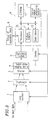
  • the processor 15 sets the diaphragm 2 to "open”, and opens/closes the shutter 3 , while controlling the strobe 7 to emit light in synchronism with the opening/closing of the shutter 3 . Then, the processor 15 receives the output signal from each pixel of the solid-state imaging device 4 via the switching module 5 , and stores the output levels of the pixels in a second picture data storage area of the picture memory 11 (step 104).
  • the release time of the shutter 3 is set so that an amount of light is incident upon each pixel, which brings the solid-state imaging device 4 to a near-overflow state (i.e., the amount of incident light is maximized without bringing the solid-state imaging device 4 to the overflow state), thereby maximizing the output level of the pixel.
  • the focus of the lens section 1 is adjusted to ⁇ , the picture imaged by the solid-state imaging device 4 is blurred to provide an even more uniform gray scale.
  • Such a picture having a uniform gray scale is preferred in detecting a pixel having a particularly low output level (i.e., a particularly dark pixel) or a pixel having a particularly high output level (i.e., a particularly bright pixel), i.e., a pixel having a defect.
  • a particularly low output level i.e., a particularly dark pixel
  • a pixel having a particularly high output level i.e., a particularly bright pixel
  • the processor 15 assumes the pixel at the coordinate position (1,0) to be the subject pixel, and extracts the output levels of all the necessary pixels from the three pictures of data, which have been stored in the picture memory 11 in steps 103-105, respectively.
  • the processor 15 further determines the amount of light incident upon the subject pixel based on Expression (8) and Expression (2) above, determines the photoelectric coefficient a and the offset output level b of the subject pixel based on Expression (7) above, and determines the presence/absence and the type of defect of the subject pixel based on Expression (10) above. If the subject pixel has a defect, the type of defect (i.e., a white blemish or a black blemish) and the coordinate position of the subject pixel are stored in the picture memory 11 .
  • the type of defect i.e., a white blemish or a black blemish
  • the coordinate i is successively varied from 0 to (10-1) so as to determine the presence/absence and the type of defect for each pixel at a coordinate position (0-(I0-1),j).
  • the determination of the presence/absence and the type of defect for all the pixels is complete when i+1 is determined to be equal to (I0-1) ("Yes” is given at step 110) while j+1 is determined to be equal to (J0-1) ("Yes” is given at step 113).
  • the processor 15 reads out the type of defect of each pixel having a defect and the coordinate position thereof from the picture memory 11 , and stores the data in the EEPROM 12 .
  • the processor 15 reads out the coordinate position (i,j) of a pixel having a defect from the EEPROM 12 , so as to identify the color displayed by the pixel having a defect based on the coordinates i and j, and switches the switching module 5 to the terminal SW2 or SW3 at a timing at which a signal is output from the pixel.
  • the processor 15 determines the color displayed by the pixel having a defect based on the coordinates i and j in a manner similar to that of steps 107, 108 and 115. Then, if the color displayed by the pixel is determined to be R or B, the processor 15 switches the switching module 5 to the terminal SW2 at a timing at which a signal is output from the pixel. If the color displayed by the pixel is determined to be G, the processor 15 switches the switching module 5 to the terminal SW3 at a timing at which a signal is output from the pixel.
  • image processes e.g., a ⁇ correction and an image compression
  • image processes e.g., a ⁇ correction and an image compression
  • the segment 5a is always connected to the terminal SW1 .
  • color filter of a primary colors Bayer pattern is described in the above-described embodiment, the present invention may alternatively be used with other types of color filter in which primary colors and complementary colors are arranged according to a given rule.
  • output characteristics of a subject photoelectric transducer in response to varied amounts of light incident upon the subject photoelectric transducer are determined, so as to detect a defect in the subject photoelectric transducer based on the output characteristics.
  • outputs of a subject photoelectric transducer in response to different amounts of incident light may be stored in the picture memory so as to determine the photoelectric coefficient a of the subject photoelectric transducer and the offset output level b of the subject photoelectric transducer in the absence of incident light, based on the amounts of incident light, the outputs of the subject photoelectric transducer therefor, and Expression (1).
  • a defect in the subject photoelectric transducer is detected by comparing the photoelectric coefficient a and the offset output level b with a predetermined reference photoelectric coefficient a 0 and a predetermined reference offset output level b 0 , respectively.
  • y(x) ax+b

Abstract

A pixel defect detector of the present invention is used for a solid-state imaging device comprising a plurality of photoelectric transducers. The pixel defect detector includes: a calculation section for obtaining output characteristics of a subject photoelectric transducer for varied amounts of light incident thereupon so as to determine the presence/absence of a defect in the subject photoelectric transducer based on the output characteristics thereof.

Description

BACKGROUND OF THE INVENTION 1. FIELD OF THE INVENTION:
The present invention relates to a pixel defect detector which is provided in a solid-state imaging device such as a CCD for automatically detecting a defect produced in the solid-state imaging device.
2. DESCRIPTION OF THE RELATED ART:
It is generally known in the art that the quality of a solid-state imaging device such as a CCD may deteriorate due to a local crystal defect (also referred to as a "blemish") which is produced therein while being manufactured. Moreover, an additional blemish may be produced in the solid-state imaging device after shipping by the irradiation of cosmic rays. Such blemishes can be classified into white blemishes and black blemishes.
Figure 6 shows a graph illustrating output characteristics in response to the amount of incident light of different photoelectric transducers (referred to also as "pixels") provided in a solid-state imaging device. In Figure 6, the solid line A represents an output characteristic of a normal pixel, the broken line B represents that of a pixel having a white blemish, and the one-dot chain line C represents that of a pixel having a black blemish. As can be seen from the output characteristic represented by the broken line B, a white blemish is a defect due to which a bias voltage is always added to an output of the pixel. Moreover, as can be seen from the output characteristic represented by-the one-dot chain line C, a black blemish is a defect by which the sensitivity of the pixel is reduced.
Conventionally, various devices and methods have been proposed in the art for detecting such a blemish in a pixel and correcting the output of such a pixel.
For example, Japanese Laid-Open Publication No. 8-195909 discloses an arrangement comprising: a ROM for storing data representing the position and the level of a CCD blemish which is already present prior to shipping; and an EEPROM for storing data representing the position and the level of a CCD blemish which is additionally produced after the shipping. According to this arrangement, the output of the CCD having a blemish is corrected based on the data stored in the ROM and the data stored in the EEPROM.
Japanese Laid-Open Publication No. 7-7675 discloses a technique in which a blemish of a CCD is detected after performing an inverse γ correction on an output signal of the CCD. The inverse γ correction is performed because once-a γ correction is performed, the amount of error occurring in the output signal of the-CCD due to the blemish is reduced, whereby the blemish detection is difficult.
Japanese Laid-Open Publication No. 62-8666 discloses a technique of substituting the output signal of a pixel having a blemish with the output signal of another pixel in the same row or column.
In the prior art, however, the detection of a blemish in a solid-state imaging device either before or after shipping requires a reference light generator for producing various (dark to bright) levels of reference light incident upon the device, an aided system, and the like. Moreover, in the prior art, the detection of a blemish in a pixel and the correction of the output from the pixel may be difficult for anyone but an expert operator. These operations are far from those which can ordinarily be done by a user.
SUMMARY OF THE INVENTION
According to one aspect of this invention, a pixel defect detector for a solid-state imaging device comprising a plurality of photoelectric transducers is provided. The pixel defect detector includes: a calculation section for obtaining output characteristics of a subject photoelectric transducer for varied amounts of light incident thereupon so as to determine the presence/absence of a defect in the subject photoelectric transducer based on the output characteristics thereof.
In one embodiment of the invention, the pixel defect detector further includes a picture memory for storing an output signal from the photoelectric transducer. The calculation section determines the output characteristics of the subject photoelectric transducer using the output signal of the subject photoelectric transducer stored in the picture memory.
In one embodiment of the invention, the output characteristics of the subject photoelectric transducer are represented by a plurality of output signals of the subject photoelectric transducer in response to different amounts of light incident thereupon, respectively.
According to another aspect of this invention, a pixel defect-detector for a solid-state imaging device comprising a plurality of photoelectric transducers is provided. The pixel defect detector includes: a picture memory for storing outputs from a subject photoelectric transducer in response to different amounts of light incident thereupon, respectively; and a calculation section for determining a photoelectric coefficient a of the subject photoelectric transducer and an offset output level b of the subject photoelectric transducer in the absence of incident light based on the amounts of incident light, the outputs from the subject photoelectric transducer therefor, and Expression (1) below, so as to compare the photoelectric coefficient a and the offset output level b with a predetermined reference photoelectric coefficient a0 and a predetermined reference offset output level b0, respectively, thereby determining the presence/absence of a defect in the subject photoelectric transducer: y(x)=ax+b    where y(x) denotes the output of the subject photoelectric transducer, and x denotes the amount of incident light.
In one embodiment of the invention, the pixel defect detector further includes an optical system for projecting a picture onto the solid-state imaging device. The output of the photoelectric transducer is determined while the optical system is defocused with respect to the solid-state imaging device.
In one embodiment of the invention, the amounts of light incident upon the subject photoelectric transducer comprise an amount of incident light when no light is incident upon the solid-state imaging device and another amount of incident light which brings the solid-state imaging device to a near-overflow state.
In one embodiment of the invention, the amount of incident light x is determined by applying, to Expression (2) below, the predetermined reference photoelectric coefficient a0, the predetermined reference offset output level b0, and a reference output signal y0: x=(y0-b0)/a0
In one embodiment of the invention, the output y0 is set to a median among outputs from a plurality of photoelectric transducers neighboring the subject photoelectric transducer.
In one embodiment of the invention, the neighboring photoelectric transducers comprise only those which display the same one of a plurality of colors to be displayed as that of the subject photoelectric transducer.
In one embodiment of the invention, the presence/absence of a defect in the subject photoelectric transducer is determined by applying the photoelectric coefficient a of the subject photoelectric transducer, the offset output level b of the subject photoelectric transducer, the reference photoelectric coefficient a0, and the reference offset output level b0, to Expression (3) below: no defect, if |a0-a|<Δa and |b0-b|<Δb    where Δa and Δb are predetermined threshold values.
In one embodiment of the invention, the presence/absence and the type of defect in the subject photoelectric transducer are determined by applying the photoelectric coefficient a of the subject photoelectric transducer, the offset output level b of the subject photoelectric transducer, the reference photoelectric coefficient a0, and the reference offset output level b0, to Expression (4) below: no defect, if |a0-a|<Δa and |b0-b|<Δb; a black blemish, if |a0-a|≥Δa; and a white blemish, if |b0-b|≥Δb    where Δa and Δb are predetermined threshold values.
In one embodiment of the invention, the reference photoelectric coefficient a0 and the reference offset output level b0 are prescribed for each of the colors to be displayed.
In one embodiment of the invention, the pixel defect detector further includes a determination section for determining a color to be displayed by the subject photoelectric transducer based on address data of the subject photoelectric transducer. The reference photoelectric coefficient a0 and the reference offset output level b0 are prescribed based on the determination by the determination section.
Thus,- the invention described herein makes possible the advantages of providing a pixel defect detector for a solid-state imaging device, which does not require a reference light generator, a special aided system, or the like, and with which the detection can be easily done by a user.
These and other advantages of the present invention will become apparent to those skilled in the art upon reading and understanding the following detailed description with reference to the accompanying figures.
BRIEF DESCRIPTION OF THE DRAWINGS
  • Figure 1 is a graph illustrating input/output characteristics of a photoelectric transducer;
  • Figure 2 is a plan view illustrating an arrangement of the primary colors in a color filter according to a primary colors Bayer pattern;
  • Figure 3 is a block diagram illustrating a digital still camera incorporating a pixel defect detector according to one embodiment of the present invention;
  • Figure 4 is a flow chart illustrating-a procedure performed by the apparatus shown in Figure 3;
  • Figure 5 is a block diagram illustrating a switching module provided in the apparatus shown in Figure 3; and
  • Figure 6 is a graph illustrating input/output characteristics of a photoelectric transducer.
  • DESCRIPTION OF THE PREFERRED EMBODIMENTS
    First, the general description of the present invention will be below.
    As described above, the prior art procedure of applying reference light from a reference light generator across a solid-state imaging device, detecting a pixel having a blemish based on an output signal of the solid-state imaging device using a special aided system, and then correcting the output of such a pixel, is far from that which can ordinarily be done by a user.
    It is assumed in the present invention that no reference light generator for applying reference light is used. In such a case, the amount of light incident upon the solid-state imaging device cannot be determined, and a pixel having a blemish cannot be identified simply by comparing an output signal of a pixel with that of another neighboring pixel. For example, referring to the graph of Figure 1, when comparing an output characteristic f1(x) of a normal (i.e., not blemished) pixel in response to an amount of incident light with an output characteristic f2(x) of a pixel having a black blemish in response to an amount of incident light, the difference (e.g., Δy1 or Δy2) between the output characteristic f1(x) and the output characteristic f2(x) varies depending upon the amount of incident light. Therefore, a pixel having a blemish cannot be identified based on such a difference unless the amount of incident light can be accurately determined. When one attempts to determine the presence/absence of a blemish based on only one difference between the output characteristic f1(x) and the output characteristic f2(x), the presence/absence of a blemish cannot be determined in a precise manner, as a white blemish and a black blemish cannot be accurately distinguished from each other.
    Thus, according to the present invention, a pixel having a blemish is identified by using a function of Expression (1) below which represents the output characteristic of a pixel of the solid-state imaging device. y(x)=ax+b
    Herein, y(x) denotes an output level of a pixel (or a photoelectric transducer) being examined (hereinafter, a "subject pixel"), x denotes an amount of incident light, a denotes a photoelectric coefficient of the pixel, and b denotes an offset output level of the pixel in the absence of incident light.
    When comparing the function of one normal pixel with that of another normal pixel, the values of the coefficients a and b for one pixel are close to those for the other pixel, respectively. Moreover, the values of the coefficients a and b for each normal pixel are substantially equal to an average reference photoelectric coefficient a0 and an average reference offset output level b0. For a pixel having a black blemish, the photoelectric coefficient a is smaller than the reference photoelectric coefficient a0. For a pixel having a white blemish, the offset output level b is larger than the reference offset output level b0.
    The photoelectric coefficient a and the offset output level b of one pixel are constant regardless of the amount of light incident thereupon. Therefore, the presence/absence and the type of defect of the pixel can be determined by obtaining the above-described function for the pixel.
    When N different amounts of incident light (from dark to bright), x0, x1, ... , xN-1, are applied to a subject pixel, thereby obtaining N output levels, y0, y1, ... , yN-1, corresponding to the subject pixel, the input/output relationship of the subject pixel can be represented by Expression (5), which is below based on Expression (1) above.
    Figure 00140001
    By using a least squares method, the photoelectric coefficient a and the offset output level b of a subject pixel can be obtained by applying the amount of light xi incident upon the subject pixel and the actual output level yi for the amount of light x to Expression (7) below, on the condition that the sum σ of squares of errors obtained by Expression (6) below is minimized (for the least squares method, see, for example, "Sensor and Signal Processing System II", pp. 10-11, 1985, Japan Society of Mechanical Engineers eds, published by Asakura Shoten).
    Figure 00140002
    Figure 00140003
    Since no reference light generator is used in the present invention, the amount of light xi incident upon a subject pixel is not the amount of reference light, and thus is not readily specified. Therefore, the amount of incident light xi is estimated before obtaining the photoelectric coefficient a and the offset output level b from Expression (7) above.
    In order to estimate the amount of light xi incident upon the subject pixel, the outputs of the subject pixel and the neighboring pixels within a prescribed pixel region are examined as follows. The term "pixel region" as used in this specification refers to a prescribed region on an imaging screen within which is included a number of pixels, including the subject pixel. The output levels of some or all of the number of pixels are examined to estimate the amount of light incident upon the subject pixel. For example, the outputs of the subject pixel and other neighboring pixels, which are located along the upper, lower, left and right sides of the subject pixel, are examined. If the number of pixels having the same type of defect is less than or equal to half of the number of the selected pixels, it is possible to obtain an output level of a normal pixel by obtaining the median y0 of the output levels of the selected pixels through a median filter represented by Expression (8) below.
    Figure 00160001
    Herein, yi (i=1, ..., 5) denotes the output level of the five pixels selected from the same pixel region.
    For example, where y1 denotes the output level of a normal pixel, y2 and y3 denote the output levels of pixels having a black blemish (smaller than the output level of the normal pixel), and y4 and y5 denote the output levels of pixels having a white blemish (larger than the output level of the normal pixel), then, the median y0 obtained through the median filter is equal to the output level y1 of the normal pixel. Alternatively, when only normal pixels are selected from a pixel region, the median among the output levels of the normal pixels is obtained.
    Once an output level y0 of a normal pixel is obtained, it is possible to obtain the amount of light x incident upon the subject pixel by applying the output level y0 to Expression (2) below. x=(y0-b0)/a0
    Herein, a0 denotes an average reference photoelectric coefficient among the normal pixels, and b0 denotes an average reference offset output level among the normal pixels.
    The output level y0 of a normal pixel in the pixel region is obtained for each of N different amounts of light (from dark to bright), x0, x1, ..., xN-1, being applied. The output level y0 is applied to Expression (2) above, so as to calculate each of the amounts of incident light, x0, x1, ..., xN-1.
    Once the amounts of light, x0, x1, ..., xN-1, incident upon the subject pixel are determined as described above, it is possible to determine the photoelectric coefficient a and the offset output level b of the subjectpixel by applying, to Expression (7) above, the determined amounts of incident light and the actual output levels y0, y1, ..., yN-1, from the subject pixel in response to the amounts of incident light.
    For displaying multiple colors, the reference photoelectric coefficient a0 varies for the respective colors to be displayed. For example, in order to produce a color display with the three primary colors R, G and B, it may -be necessary to prescribe a reference photoelectric coefficient a0 for each of the primary colors R, G and B. In such a case, a subject pixel in a pixel region and pixels which are in the same pixel region and which represent the same color as that of the subject pixel are selected, and the median output level among the selected pixels is obtained by Expression (8) above. Then, the amount of incident light x is calculated based on Expression (2) above, and the photoelectric coefficient a is calculated based on Expression (7) above.
    Instead of a0 in Expression (2) above, values a0R, a0G and a0B are used which denote predetermined reference photoelectric coefficients for the primary colors R, G and B, respectively. Moreover, the photoelectric coefficients obtained for the primary colors R, G and B are denoted by aR, aG and aB, respectively.
    It is not necessary to obtain the offset output level b and the reference offset output level b0 for each of the primary colors, but these values can be commonly used among the primary colors.
    Where no special device, such as a reference light generator, is used as in the present invention, it is very difficult to make a uniform amount of light be incident across the solid-state imaging device. Therefore, in the present invention, it may be necessary to minimize the size of a pixel region including the subject pixel so that a uniform amount of light is incident across the pixel region.
    Figure 2 illustrates a color filter of a primary colors Bayer pattern. When such a color filter is employed for producing a color display, a pixel region mask1 is prescribed surrounding a subject pixel R1 for the primary color R, and nine pixels R1, R0 are selected from the pixel region mask1 to obtain the amount of light incident upon the subject pixel. Similarly, for the primary color B, a pixel region mask2 is prescribed surrounding a subject pixel B1 and nine pixels B1, B0 are selected from the pixel region mask2 to obtain the amount of light incident upon the subject pixel. For the primary color G, a pixel region mask3 or mask4 is prescribed surrounding a subject pixel G1 and nine or five pixels G1 , G0 are selected from the pixel region mask3 or mask4 to obtain the amount of light incident upon the subject pixel.
    The relatively small pixel region mask4 is used to obtain an accurate amount of light incident upon the subject pixel G1 because the human eye is most sensitive to the primary color G of the three primary colors.
    In this way, the amount of incident light and the output level are obtained for each subject pixel, so as to obtain one of the photoelectric coefficients aR, aG and aB corresponding to the color displayed by the subject pixel, and the reference offset output level b0 which is common to the primary colors R, G and B. Then, the presence/absence and the type of defect are determined based on Expressions (9), (10) and (11) below.
    Where the subject pixel displays the primary color R, the subject pixel has: no defect if a0R-aR <Δ aR and b0-b <Δ bR; a black blemish if a0R-aR ≥ΔaR; and a white blemish if b0-b ≥ΔbR.
    Where the subject pixel displays the primary color B, the subject pixel has: no defect if a0B-aB <Δ aB and b0-b <Δ bB; a black blemish if a0B-aB ≥ΔaB; and a white blemish if b0-b ≥ΔbB.
    Where the subject pixel displays the primary color G, the subject pixel has: no defect if a0G-aG <Δ aG and b0-b <Δ bG; a black blemish if a0G-aG ≥ΔaG; and a white blemish if b0-b ≥ΔbG.
    Herein, ΔaR, ΔaB, ΔaG, and ΔbR, ΔbB, ΔbG are threshold values, which are prescribed separately for the respective primary colors R, G and B so as to improve the detection/determination precision.
    In order to obtain the photoelectric coefficient a and the offset output level b based on Expression (7) above, the left side of Expression (7) needs to be non-zero, i.e., Expression (12) below needs to hold. In other words, the series of N functions in Expression (5) above need to be independent from one another. Under a condition close to the ideal condition (e.g., where substantially no white noise exists), the series of N functions are correlated to one another, whereby Expression (12) below does not hold. Then, the photoelectric coefficient a=a0, and the offset output level b=b0.
    Figure 00220001
    In the manner as described above, the presence/absence and the type of defect are determined for each subject pixel. Then, if a subject pixel has a defect, the output level of the pixel will be corrected.
    The bias voltage added to the output of a pixel having a white blemish varies depending upon the temperature, while the sensitivity of a pixel having a black blemish is deteriorated. Therefore, simple addition or subtraction of a constant voltage to/from the output of such a pixel may not sufficiently correct the output of the pixel. It is preferred to correct the output signal of a pixel having a defect using the output signal of each of one or more neighboring pixels.
    For correcting the output signal of the pixel having a defect, using the output signal of each of one or more pixels which are horizontally neighboring the subject pixel along with those of one or more pixels which are vertically neighboring the subject pixel is more preferred for the following reason than using only the output signal of one or more pixels which are neighboring the subject pixel either in the horizontal or vertical direction. For example, when the subject pixel having a defect is located along an edge of the object being imaged, the output of a pixel horizontally neighboring the subject pixel is likely to be substantially different from that of a pixel vertically neighboring the subject pixel. In such a case, correcting the output signal of the subject pixel using only the output signal of a pixel neighboring the subject pixel either in the horizontal or vertical direction may result in false colors.
    Moreover, it is preferred to perform the output level correction separately for the respective primary colors to be displayed. For example, where the primary colors R, G and B are displayed, it is preferred to perform a more precise correction for the primary color G using the color distribution of the primary colors Bayer pattern because the primary color G is more important than the other primary colors R and B.
    For example, as illustrated in Figure 2, the pixel region mask1 is prescribed surrounding the subject pixel R1 for the primary color R, while the pixel region mask2 is prescribed surrounding the subject pixel B1 for the primary color B. Assuming that the corrected output level of the subject pixel R1 or B1 is y(i,j), the average of the output levels of the other eight pixels, which are in the same pixel region and which represent the same color as that of the subject pixel R1 or B1, is determined based on Expression (13) below. y(i,j)= [y(i-2,j-2)+y(i,j-2)+y(i+2,j-2) +y(i-2,j)+y(i+2,j)+y(i-2,j+2) +y(i,j+2)+y(i+2,j+2)]/8
    For the primary color G, the pixel region mask4 is prescribed surrounding the subject pixel G1, also as illustrated in Figure 2. Assuming that the corrected output level of the subject pixel G1 is y(i,j), the average of the output levels of the other four pixels, which are in the same pixel region and which represent the same color as that of the subject pixel G1, is determined based on Expression (14) below. y(i,j)= [y(i-1,j-1)+y(i+1,j-1)+y(i-1,j+1) +y(i+1,j+1)]/4
    In Expressions (13) and (14), designations such as "(i,j)" denote coordinate points.
    The relatively small pixel region mask4 is used to obtain an accurate amount of light incident upon the subject pixel G1 because the human eye is most sensitive to the primary color G of the three primary colors.
    A pixel defect detector according to one embodiment of the present invention is used for detecting a pixel defect in a solid-state imaging device (e.g., a CCD) such as a digital still camera. The digital still camera is provided with a special mode of operation for the pixel defect detection. In the special mode, the detection of a defect in a solid-state imaging device is substantially automatically performed in response to a predetermined operation by a user. Thus, the position of a pixel having a defect and the output characteristics of the pixel are recorded. Then, in a normal shooting mode, output signals from each pixel having a -defect are corrected based on the recorded data.
    For the pixel defect detection, a y correction is not performed on the output signal of the solid-state imaging device so that the amount of error occurring in the output signal from the pixel having a defect will not be reduced.
    In the pixel defect detector according to this embodiment of the present invention, the output characteristics of the solid-state imaging device are determined by applying varied amounts of light to the solid-state imaging device. Various functions of the digital still camera such as the diaphragm, the strobe, and the shutter speed, may be used alone or in combination so as to vary the amounts of light incident upon the solid-state imaging device.
    In the pixel defect detection mode, the digital still camera is preferably defocused so that a uniform level of light is incident across the solid-state imaging device. For example, even when a wall or a panel having a uniform gray level is imaged by the digital still camera so as to obtain a uniform level of light incident across the solid-state imaging device, there may be some non-uniformity in the gray level of the object and/or some non-uniformity in the illumination for the object. By defocusing the digital still camera, it is possible to blur such non-uniformity, thereby applying a more uniform level of light incident across the solid-state imaging device.
    Figure 3 is a block diagram illustrating a digital still camera incorporating the pixel defect detector according to one embodiment of the present invention. Referring to Figure 3, light is incident upon a solid-state imaging device (e.g., a CCD) 4 via a lens section 1, a diaphragm 2 and a shutter 3, thereby projecting a picture onto an imaging screen of the solid-state imaging device 4. The solid-state imaging device 4 includes a plurality of photoelectric transducers (pixels) arranged in rows and columns, and the picture is projected onto such an arrangement of pixels. The output signals from these pixels are successively sent to a picture processing section 6 via a switching module 5. A strobe 7 emits light in synchronism with the opening/closing of the shutter 3 so as to irradiate the object. A group of operation keys 8 are used by a user to operate the digital still camera.
    The picture processing section 6 primarily comprises a picture memory 11, an EEPROM 12, a data table 13, a control signal producing section 14, and a processor 15. The picture memory 11 stores the output levels of the pixels of the solid-state imaging device 4, i.e., picture data representing the imaged picture. Typically, the picture memory 11 is capable of storing at least three pictures. The EEPROM 12 stores: photoelectric coefficients a0R, a0G, a0B, threshold values ΔaR, AaG, ΔaB, and ΔbR, ΔbG, ΔbB, which are predetermined for the respective primary colors R, G and B; the reference offset output level b0; and the size of the imaging screen of the solid-state imaging device 4 (represented by the number of pixels along the horizontal direction I0 times that along the vertical direction J0 on the imaging screen). The data table 13 stores various data such as data used for performing a γ correction on the picture data, and data used for performing a JPEG compression on the picture data. The control signal producing section 14 produces and outputs a control signal for controlling, in response to an instruction from the processor 15, the lens section 1, the diaphragm 2, the shutter 3, the solid-state imaging device 4, the switching module 5, the strobe 7, etc. The processor 15 controls the picture processing section 6, processes picture data and performs various other arithmetic operations.
    The picture processing section 6 may be produced on a single-chip LSI.
    In the digital still camera of this embodiment of the present invention, the normal shooting mode can be selected by operating the group of operation keys 8.
    In the normal shooting mode, in response to an appropriate operation of the group of operation keys 8, the processor 15: drives the lens section 1 so as to focus the picture being projected onto the imaging screen of the solid-state imaging device 4 (auto-focus); adjusts the stop of the diaphragm 2; opens/closes the shutter 3; and controls the strobe 7 to emit light in synchronism with the opening/closing of the shutter 3. As a result, the picture is imaged by the solid-state imaging device 4. Then, the processor 15: receives the picture data from the solid-state imaging device 4 via the switching module 5; temporarily stores the picture data in the picture memory 11; performs image processes (e.g., a γ correction and an image compression) on the picture data; and sends the processed picture data to a recording mechanism of a recording medium (not shown). The recording mechanism records the processed picture data on the recording medium.
    In the digital still camera of this embodiment of the present invention, the pixel defect detection mode can be selected by operating the group of operation keys 8. When the pixel defect detection mode is selected, the processor 15 performs the procedure illustrated in the flow chart of Figure 4 so as to automatically detect a pixel having a defect and store the coordinate position of the pixel in the EEPROM 12. Thus, the detection of a defect pixel can be done by a user without requiring any special device or knowledge.
    First, the processor 15 prepares an area in the picture memory 11 for storing three pictures, and inactivates functions such as the γ correction, the image compression, and the auto-focus of the lens section 1 (step 101). The processor 15 further drives the lens section 1 so as to set the focus of the lens section 1 to ∞, for example (step 102).
    After setting the release time of the shutter 3 to zero, the switching module 5 receives the output signal from each pixel of the solid-state imaging device 4 via the switching module 5, and stores the output levels of the pixels in a first picture data storage area of the picture memory 11 (step 103).
    When the release time of the shutter 3 is set to zero, the amount of light incident upon each pixel of the solid-state imaging device 4 is zero, whereby the output of each pixel is at the lowest level.
    Subsequently, the processor 15 sets the diaphragm 2 to "open", and opens/closes the shutter 3, while controlling the strobe 7 to emit light in synchronism with the opening/closing of the shutter 3. Then, the processor 15 receives the output signal from each pixel of the solid-state imaging device 4 via the switching module 5, and stores the output levels of the pixels in a second picture data storage area of the picture memory 11 (step 104).
    In the above-described operation, the release time of the shutter 3 is set so that an amount of light is incident upon each pixel, which brings the solid-state imaging device 4 to a near-overflow state (i.e., the amount of incident light is maximized without bringing the solid-state imaging device 4 to the overflow state), thereby maximizing the output level of the pixel. As described above, it is preferable for detecting a pixel having a defect to use a wall or a panel having a uniform gray level, so that the picture imaged by the solid-state imaging device 4 has a substantially uniform gray scale. Moreover, since the focus of the lens section 1 is adjusted to ∞, the picture imaged by the solid-state imaging device 4 is blurred to provide an even more uniform gray scale. Such a picture having a uniform gray scale is preferred in detecting a pixel having a particularly low output level (i.e., a particularly dark pixel) or a pixel having a particularly high output level (i.e., a particularly bright pixel), i.e., a pixel having a defect.
    Moreover, the processor 15 sufficiently stops down the diaphragm 2, and opens/closes the shutter 3, while controlling the strobe 7 to emit light in synchronism with the opening/closing of the shutter 3. Then, the processor 15 receives the output signal from each pixel of the solid-state imaging device 4 via the switching module 5, and stores the output levels of the pixels in a third picture data storage area of the picture memory 11 (step 105).
    Since the shutter 3 is opened/closed while sufficiently stopping down the diaphragm 2 with the strobe 7 emitting light, the amount of light incident upon each pixel of the solid-state imaging device 4, and thus the output level of each pixel, are between those of step 103 and those of step 104, respectively. The photographed object of the digital still camera is preferably the same in steps 104 and 105. In step 105, it is preferable to image a wall or a panel having a uniform gray level, as described above. Since the focus of the lens section 1 is adjusted to ∞, the picture imaged by the solid-state imaging device 4 is blurred to provide a uniform gray scale.
    In this way, the following three output levels are stored in the picture memory 11 in steps 103, 104 and 105, respectively: the output level of each pixel of the solid-state imaging device 4 for the minimum amount of incident light; the output level of each pixel of the solid-state imaging device 4 for an intermediate amount of incident light; and the output level of each pixel of the solid-state imaging device 4 for the maximum amount of incident light.
    Thus, the input/output relationship as represented by Expression (5) above (N-1=2) holds for each pixel of the solid-state imaging device 4.
    Then, the processor 15 successively addresses the pixels of the solid-state imaging device 4 by successively designating addresses, i.e., the coordinate positions (i,j). Each time a coordinate position (i,j) is designated, it is determined which of the primary colors R, G and B is to be displayed by the pixel at the designated coordinate position (i,j) based on the coordinates i and j of the position, while calculating the above-described function for the addressed pixel so as to determine the presence/absence and the type of defect of the pixel.
    In this embodiment of the present invention, a color filter of a primary colors Bayer pattern as illustrated in Figure 2 is used, whereby it is possible to determine which of the primary colors R, G and B is to be displayed by the pixel at the coordinate position (i,j) based on the coordinates i and j of the position.
    First, the processor 15 initializes the coordinate position (i,j) to (0,0). Moreover, the processor 15 reads out, from the EEPROM 12, various data such as: the photoelectric coefficients a0R, a0G, a0B, threshold values ΔaR, ΔaG, ΔaB, and ΔbR, ΔbG, ΔbB, which are predetermined for the respective primary colors R, G and B; the reference offset output level bo; and the size of the imaging screen of the solid-state imaging device 4 (represented by the number of pixels along the horizontal direction (I0-1) times that along the vertical direction (J0-1) on the imaging screen) (step 106).
    Then, the processor 15 determines whether each of the coordinates i and j of the coordinate position (i,j) is an even number (steps 107, 108).
    After the initialization, each of the initialized coordinates i=0 and j=0 is determined to be an even number (i.e., "yes" is given at step 107 and at step 108). In the primary colors Bayer pattern as illustrated in Figure 2, any pixel at a coordinate position where the coordinates i and j are both an even number displays the primary color R. Therefore, the presence/absence and the type of defect of the pixel displaying the primary color R are determined (step 109).
    In step 109, the processor 15 assumes the pixel at the coordinate position (0,0) to be the subject pixel, and extracts the output levels of all the necessary pixels from the three pictures of data, which have been stored in the picture memory 11 in steps 103-105, respectively. The processor 15 further determines the amount of light incident upon the subject pixel based on Expression (8) and Expression (2) above, determines the photoelectric coefficient a and the offset output level b of the subject pixel based on Expression (7) above, and determines the presence/absence and the type of defect of the subject pixel based on Expression (9) above. If the subject pixel has a defect, the type of defect (i.e., a white blemish or a black blemish) and the coordinate position of the subject pixel are stored in the picture memory 11.
    Thereafter, the processor 15 determines whether the next coordinate position (i+1,j) to the right falls beyond the horizontal size (I0-1) of the imaging screen (step 110). If "No" is given at step 110, the processor 15 then adds 1 to i so as to update the coordinate position (i,j) (step 111). Then, the process returns to step 107.
    The coordinate i of the updated coordinate position (i,j) is now 1, an odd number. Thus, i is determined to be an odd number ("No" is given at step 107), while j is still determined to be an even number ("Yes" is given at step 115). In the primary colors Bayer pattern as illustrated in Figure 2, any pixel at such a coordinate position displays the primary color G. Therefore, the presence/absence and the type of defect of the pixel displaying the primary color G are determined (step 112).
    In step 112, the processor 15 assumes the pixel at the coordinate position (1,0) to be the subject pixel, and extracts the output levels of all the necessary pixels from the three pictures of data, which have been stored in the picture memory 11 in steps 103-105, respectively. The processor 15 further determines the amount of light incident upon the subject pixel based on Expression (8) and Expression (2) above, determines the photoelectric coefficient a and the offset output level b of the subject pixel based on Expression (7) above, and determines the presence/absence and the type of defect of the subject pixel based on Expression (10) above. If the subject pixel has a defect, the type of defect (i.e., a white blemish or a black blemish) and the coordinate position of the subject pixel are stored in the picture memory 11.
    In the primary colors Bayer pattern as illustrated in Figure 2, the pixels at coordinate positions (i,0) alternately correspond to the primary colors R and G. Therefore, subsequently for other pixels at coordinate positions (i,0), step 109 and step 112 are alternately performed as described above so as to determine the presence/absence and the type of defect of the subject pixel at each coordinate position (i,0) while storing such data for any subject pixel having a defect.
    When i+1 is equal to I0 ("Yes" is given at step 110), the processor 15 then determines whether the next coordinate position (i,j+1) below the position (i,j) falls beyond the vertical size (J0-1) of the imaging screen (step 113). If "No" is given at step 113, the processor 15 then adds 1 to j so as to update the coordinate j to 1 (step 114). Since the coordinate j is an odd number ("No" is given at step 108 and at step 115), either step 112 or step 116 is performed depending upon the determination of whether the coordinate i is an even number (step 107).
    In step 112, the presence/absence and the type of defect of the pixel displaying the primary color G are determined as described above. In step 116, the presence/absence and the type of defect of the pixel displaying the primary color B are determined. For the determination, the processor 15 extracts the output levels of all the necessary pixels from the three pictures of data, which have been stored in the picture memory 11 in steps 103-105, respectively. The processor 15 further determines the amount of light incident upon the subject pixel based on Expression (8) and Expression (2) above, determines the photoelectric coefficient a and the offset output level b of the subject pixel based on Expression (7) above, and determines the presence/absence and the type of defect of the subject pixel based on Expression (11) above. If the subject pixel has a defect, the type of defect (i.e., a white blemish or a black blemish) and the coordinate position of the subject pixel are stored in the picture memory 11.
    In the primary colors Bayer pattern as illustrated in Figure 2, the pixels at coordinate positions (i,1) alternately correspond to the primary colors B and G. Therefore, subsequently for other pixels at coordinate positions (i,1), step 116 and step 112 are alternately performed as described above so as to determine the presence/absence and the type of defect of the subject pixel at each coordinate position (i,1) while storing such data for any subject pixel having a defect.
    Subsequently, as the coordinate j is incremented, the coordinate i is successively varied from 0 to (10-1) so as to determine the presence/absence and the type of defect for each pixel at a coordinate position (0-(I0-1),j). The determination of the presence/absence and the type of defect for all the pixels is complete when i+1 is determined to be equal to (I0-1) ("Yes" is given at step 110) while j+1 is determined to be equal to (J0-1) ("Yes" is given at step 113). Then, the processor 15 reads out the type of defect of each pixel having a defect and the coordinate position thereof from the picture memory 11, and stores the data in the EEPROM 12.
    When the above-described shooting mode is selected after the type of defect of each pixel of the solid-state imaging device 4 having a defect and the coordinate position thereof have been stored in the EEPROM 12, the following process is performed to correct the output level of each defect pixel.
    As the normal shooting mode is selected by the operation of the group of operation keys 8, a picture is imaged by the solid-state imaging device 4, and the processor 15 receives picture data from the solid-state imaging device 4 via the switching module 5.
    The switching module 5 has a structure as illustrated in Figure 5, and comprises three terminals SW1, SW2 and SW3. When a segment 5a is switched to the terminal SW1, the output of the solid-state imaging device 4 is directly transmitted to the processor 15, thereby storing the output level of each pixel in the picture memory 11.
    The processor 15 reads out the coordinate position (i,j) of a pixel having a defect from the EEPROM 12, so as to identify the color displayed by the pixel having a defect based on the coordinates i and j, and switches the switching module 5 to the terminal SW2 or SW3 at a timing at which a signal is output from the pixel. In particular, the processor 15 determines the color displayed by the pixel having a defect based on the coordinates i and j in a manner similar to that of steps 107, 108 and 115. Then, if the color displayed by the pixel is determined to be R or B, the processor 15 switches the switching module 5 to the terminal SW2 at a timing at which a signal is output from the pixel. If the color displayed by the pixel is determined to be G, the processor 15 switches the switching module 5 to the terminal SW3 at a timing at which a signal is output from the pixel.
    When the processor 15 receives the output signal of a defect pixel of the primary color R or B through the terminal SW2 of the switching module 5, the processor 15 performs the calculation of Expression (13) above so as to determine-the output level of the defect pixel (after data necessary for performing the calculation of Expression (13) above has been transmitted from the solid-state imaging device 4 to the picture memory 11), and stores the determined output level in an address in the picture memory 11 for the defect pixel.
    When the processor 15 receives the output signal of a defect pixel of the primary color G through the terminal SW3 of the switching module 5, the processor 15 performs the calculation of Expression (14) above so as to determine the output level of the defect pixel (after data necessary for performing the calculation of Expression (14) above has been transmitted from the solid-state imaging device 4 to the picture memory 11), and stores the determined output level in an address in the picture memory 11 for the defect pixel.
    Thus, by switching the segment 5a of the switching module 5 to the terminal SW1, SW2 or SW3, it is possible to correct the output level of the defect pixel in a substantially real-time manner while storing the picture data from the solid-state imaging device 4 in the picture memory 11.
    Thereafter, image processes (e.g., a γ correction and an image compression) are performed on the picture data stored in the picture memory 11, and the processed picture data is sent to a recording mechanism of a recording medium (not shown) so as to record the processed picture data on the recording medium.
    Instead of determining the color displayed by the pixel having a defect based on the coordinates i and j in a manner similar to that of steps 107, 108 and 115 as illustrated in Figure 4, it is possible to perform the determination while utilizing the fact that i or j is an even number when the least significant bit thereof is "0", and is an odd number when it is "1". Thus, the color displayed by the pixel is determined to be R or B if the XOR between i and j is false, and G if it is true.
    While the above-described pixel defect detection mode is selected, the segment 5a is always connected to the terminal SW1.
    As is apparent from the description above, with the digital still camera of this embodiment of the present invention, it is possible to automatically detect the coordinate position of a pixel having a defect and the type of defect and correct the output signal of the defect pixel, only by obtaining three pictures of data through multiple picture shooting operations, without requiring a reference light generator, a special aided system, or the like. Therefore, even a user can easily perform the detection and correction of defect pixels.
    The present invention is not limited to the above-described particular embodiment. Various modifications can be made to the above-described embodiment. For example, while the photoelectric coefficient a and the offset output level b of each pixel are determined based on three output levels therefrom in response to three different amounts of incident light, respectively, in the above-described embodiment, the photoelectric coefficient a and the offset output level b may alternatively be determined based on two or four output levels for two or four different amounts of incident light.
    When the photoelectric coefficient a and the offset output level b are determined based on two output levels for two different amounts of incident light, Expressions (5), (6) and (7) above may be unnecessary. Instead, the photoelectric coefficient a and the offset output level b may be obtained by determining two different amounts of incident light based on Expressions (8) and (2) and detecting two output levels from a pixel in response to the two amounts of incident light.
    In the above-described embodiment, an output of a pixel is approximated by a linear function so that the scale of the arithmetic circuit, the amount of calculation and the time required for calculation are within the practical range. Strictly speaking, the output characteristic of a photoelectric transducer is non-linear. When it is difficult to approximate the output characteristic of the photoelectric transducer with a single linear function, a combination of a plurality of linear functions or another type of function may be used provided that the possible increase in the scale of the arithmetic circuit, the amount of calculation and the time required for calculation is minimized. With any type of function being used, the presence/absence and the type of defect of a pixel can be determined by representing the actual output characteristic of the pixel in the function and comparing the coefficients of the function with one another.
    The output level of a normal pixel may alternatively be determined by any appropriate means other than the use of the median filter of Expression (8) above. For example, the output level of a normal pixel may be determined by using the median filter after excluding the maximum and minimum output levels among those of the pixels neighboring the subject pixel within the same pixel region, or alternatively by performing a well-known statistical operation on the output levels of the pixels neighboring the subject pixel within the same pixel region. Moreover, various pixel regions may be prescribed surrounding the subject pixel, other than those described above.
    While a CCD is described as an exemplary solid-state imaging device in the above-described embodiment, the present invention is not limited thereto. For example, the present invention may alternatively be used for other types of solid-state imaging device such as CID or CPD. Moreover, the present invention may alternatively be used for solid-state imaging apparatuses other than a digital still camera, such as a video camera, or a film scanner.
    While a color filter of a primary colors Bayer pattern is described in the above-described embodiment, the present invention may alternatively be used with other types of color filter in which primary colors and complementary colors are arranged according to a given rule.
    As described above, according to the present invention, output characteristics of a subject photoelectric transducer in response to varied amounts of light incident upon the subject photoelectric transducer are determined, so as to detect a defect in the subject photoelectric transducer based on the output characteristics.
    Alternatively, according to the present invention, outputs of a subject photoelectric transducer in response to different amounts of incident light may be stored in the picture memory so as to determine the photoelectric coefficient a of the subject photoelectric transducer and the offset output level b of the subject photoelectric transducer in the absence of incident light, based on the amounts of incident light, the outputs of the subject photoelectric transducer therefor, and Expression (1). A defect in the subject photoelectric transducer is detected by comparing the photoelectric coefficient a and the offset output level b with a predetermined reference photoelectric coefficient a0 and a predetermined reference offset output level b0, respectively. y(x)=ax+b
    Herein, y(x) denotes the output of the subject photoelectric transducer, and x denotes the amount of incident light.
    As described above, the output characteristic of the subject photoelectric transducer is determined, so as to detect a defect of the subject photoelectric transducer based on the output characteristic. In this way, a reference light generator, a special aided system, or the like, as in the prior art, is not required, whereby even an ordinary user can easily detect a defect of a photoelectric transducer. Not only the presence/absence of the defect, but also the type of defect, can be determined.
    Moreover, according to the present invention, the output of a photoelectric transducer is determined while the solid-state imaging device is defocused. Therefore, a substantially uniform light is incident upon a pixel region surrounding the subject photoelectric transducer. Therefore, it is possible to identify the output signal of a normal photoelectric transducer based on output signals from a plurality of photoelectric transducers in the same pixel region, thereby estimating the actual amount of incident light.
    Furthermore, an amount of incident light which is measured when no light is incident upon the solid-state imaging device, and another amount of incident light which brings the solid-state imaging device to a near-overflow state. These amounts of incident light can easily be obtained by appropriately controlling the shutter speed, the diaphragm, the strobe, and the like, of a video camera or a digital still camera.
    For a color display, photoelectric transducers for different colors are separately examined. Therefore, it is possible to accurately determine the presence/absence and the type of defect of the photoelectric transducer.
    Moreover, for a color display, the color displayed by each pixel is determined based on address data (i.e., the coordinate position) of the pixel, thereby allowing the calculation to be performed faster.
    Various other modifications will be apparent to and can be readily made by those skilled in the art without departing from the scope and spirit of this invention. Accordingly, it is not intended that the scope of the claims appended hereto be limited to the description as set forth herein, but rather that the claims be broadly construed.

    Claims (17)

    1. A pixel defect detector for a solid-state imaging device comprising a plurality of photoelectric transducers, the pixel defect detector comprising:
         a calculation section for obtaining output characteristics of a subject photoelectric transducer for varied amounts of light incident thereupon so as to determine the presence/absence of a defect in the subject photoelectric transducer based on the output characteristics thereof.
    2. A pixel defect detector for a solid-state imaging device according to claim 1, wherein:
      the pixel defect detector further comprises a picture memory for storing an output signal from the photoelectric transducer; and
      the calculation section determines the output characteristics of the subject photoelectric transducer using the output signal of the subject photoelectric transducer stored in the picture memory.
    3. A pixel defect detector for a solid-state imaging device according to claim 1, wherein:
         the output characteristics of the subject photoelectric transducer are represented by a plurality of output signals of the subject photoelectric transducer in response to different amounts of light incident thereupon, respectively.
    4. A pixel defect detector for a solid-state imaging device comprising a plurality of photoelectric transducers, the pixel defect detector comprising:
      a picture memory for storing outputs from a subject photoelectric transducer in response to different amounts of light incident thereupon, respectively; and
      a calculation section for determining a photoelectric coefficient a of the subject photoelectric transducer and an offset output level b of the subject photoelectric transducer in the absence of incident light based on the amounts of incident light, the outputs from the subject photoelectric transducer therefor, and Expression (1) below, so as to compare the photoelectric coefficient a and the offset output level b with a predetermined reference photoelectric coefficient a0 and a predetermined reference offset output level b0, respectively, thereby determining the presence/absence of a defect in the subject photoelectric transducer: y(x)=ax+b    where y(x) denotes the output of the subject photoelectric transducer, and x denotes the amount of incident light.
    5. A pixel defect detector for a solid-state imaging device according to claim 1, wherein:
      the pixel defect detector further comprises an optical system for projecting a picture onto the solid-state imaging device; and
      the output of the photoelectric transducer is determined while the optical system is defocused with respect to the solid-state imaging device.
    6. A pixel defect detector for a solid-state imaging device according to claim 4, wherein:
      the pixel defect detector further comprises an optical system for projecting a picture onto the solid-state imaging device; and
      the output of the photoelectric transducer is determined while the optical system is defocused with respect to the solid-state imaging device.
    7. A pixel defect detector for a solid-state imaging device according to claim 1, wherein:
         the amounts of light incident upon the subject photoelectric transducer comprise an amount of incident light when no light is incident upon the solid-state imaging device and another amount of incident light which brings the solid-state imaging device to a near-overflow state.
    8. A pixel defect detector for a solid-state imaging device according to claim 4, wherein:
         the amounts of light incident upon the subject photoelectric transducer comprise an amount of incident light when no light is incident upon the solid-state imaging device and another amount of incident light which brings the solid-state imaging device to a near-overflow state.
    9. A pixel defect detector for a solid-state imaging device according to claim 4, wherein:
         the amount of incident light x is determined by applying, to Expression (2) below, the predetermined reference photoelectric coefficient a0, the predetermined reference offset output level b0, and a reference output signal y0: x=(y0-b0)/a0
    10. A pixel defect detector for a solid-state imaging device according to claim 9, wherein:
         the output y0 is set to a median among outputs from a plurality of photoelectric transducers neighboring the subject photoelectric transducer.
    11. A pixel defect detector for a solid-state imaging device according to claim 10, wherein:
         the neighboring photoelectric transducers comprise only those which display the same one of a plurality of colors to be displayed as that of the subject photoelectric transducer.
    12. A pixel defect detector for a solid-state imaging device according to claim 4, wherein:
         the presence/absence of a defect in the subject photoelectric transducer is determined by applying the photoelectric coefficient a of the subject photoelectric transducer, the offset output level b of the subject photoelectric transducer, the reference photoelectric coefficient a0, and the reference offset output level b0, to Expression (3) below: no defect, if a0-a <Δ a and b0-b <Δ b    where Δa and Δb are predetermined threshold values.
    13. A pixel defect detector for a solid-state imaging device according to claim 4, wherein:
         the presence/absence and the type of defect in the subject photoelectric transducer are determined by applying the photoelectric coefficient a of the subject photoelectric transducer, the offset output level b of the subject photoelectric transducer, the reference photoelectric coefficient a0, and the reference offset output level b0, to Expression (4) below: no defect, if a0-a <Δ a and b0-b <Δ b; a black blemish, if a0-a ≥Δa; and a white blemish, if b0-b ≥Δb ...    where Δa and Δb are predetermined threshold values.
    14. A pixel defect detector for a solid-state imaging device according to claim 12, wherein:
         the reference photoelectric coefficient a0 and the reference offset output level b0 are prescribed for each of the colors to be displayed.
    15. A pixel defect detector for a solid-state imaging device according to claim 13, wherein:
         the reference photoelectric coefficient a0 and the reference offset output level b0 are prescribed for each of the colors to be displayed.
    16. A pixel defect detector for a solid-state imaging device according to claim 12, wherein:
      the pixel defect detector further comprises a determination section for determining a color to be displayed by the subject photoelectric transducer based on address data of the subject photoelectric transducer; and
      the reference photoelectric coefficient a0 and the reference offset output level b0 are prescribed based on the determination by the determination section.
    17. A pixel defect detector for a solid-state imaging device according to claim 13, wherein:
      the pixel defect detector further comprises a determination section for determining a color to be displayed by the subject photoelectric transducer based on address data of the subject photoelectric transducer; and
      the reference photoelectric coefficient a0 and the reference offset output level b0 are prescribed based on the determination by the determination section.
    EP99307068A 1998-09-08 1999-09-06 Pixel defect detector for solid-state imaging device Withdrawn EP0986249A3 (en)

    Applications Claiming Priority (2)

    Application Number Priority Date Filing Date Title
    JP25442898 1998-09-08
    JP25442898A JP3587433B2 (en) 1998-09-08 1998-09-08 Pixel defect detection device for solid-state imaging device

    Publications (2)

    Publication Number Publication Date
    EP0986249A2 true EP0986249A2 (en) 2000-03-15
    EP0986249A3 EP0986249A3 (en) 2002-07-17

    Family

    ID=17264857

    Family Applications (1)

    Application Number Title Priority Date Filing Date
    EP99307068A Withdrawn EP0986249A3 (en) 1998-09-08 1999-09-06 Pixel defect detector for solid-state imaging device

    Country Status (6)

    Country Link
    US (1) US7106371B1 (en)
    EP (1) EP0986249A3 (en)
    JP (1) JP3587433B2 (en)
    KR (1) KR100335529B1 (en)
    CN (1) CN1245825C (en)
    TW (1) TW453110B (en)

    Cited By (6)

    * Cited by examiner, † Cited by third party
    Publication number Priority date Publication date Assignee Title
    EP1737213A1 (en) * 2005-06-21 2006-12-27 Samsung Electronics Co, Ltd Shading Profile Value Correction Method and Image Scanning Device
    WO2008027475A2 (en) * 2006-08-31 2008-03-06 Micron Technology, Inc. Image sensor defect identification using blurring techniques
    EP2242254A1 (en) * 2008-01-24 2010-10-20 Hamamatsu Photonics K.K. Solid-state imaging device and frame data correcting method
    US8625741B2 (en) 2008-07-17 2014-01-07 Hamamatsu Photonics K.K. Solid-state image pickup device
    US9137466B2 (en) 2006-08-30 2015-09-15 Micron Technology, Inc. Image sensor defect identification using optical flare
    WO2015107254A3 (en) * 2014-01-15 2016-07-14 Nokia Technologies Oy An apparatus, method and computer program for determining a status of pixels in an image sensor

    Families Citing this family (22)

    * Cited by examiner, † Cited by third party
    Publication number Priority date Publication date Assignee Title
    US7365783B2 (en) 2001-03-16 2008-04-29 Olympus Corporation Image pickup apparatus which stores initial defect data concerning image pickup device and data on later developed defects
    JP4583680B2 (en) * 2001-09-28 2010-11-17 パナソニック株式会社 Solid-state imaging device
    KR100684375B1 (en) * 2001-12-04 2007-02-20 포니 고교 가부시키가이샤 Image processing method and image processor
    DE10205691A1 (en) * 2002-02-04 2003-08-14 Pilz Gmbh & Co Method for checking the functional reliability of an image sensor and device with an image sensor
    JP3912672B2 (en) * 2002-07-05 2007-05-09 ソニー株式会社 Solid-state imaging device and pixel defect inspection method thereof
    JP4179079B2 (en) * 2002-08-30 2008-11-12 株式会社ニコン Electronic camera and control program thereof
    KR100752283B1 (en) * 2002-11-07 2007-08-29 롬 가부시키가이샤 Area image sensor
    JP2004320128A (en) 2003-04-11 2004-11-11 Mega Chips Corp Defective pixel correction device
    JP4255819B2 (en) * 2003-12-11 2009-04-15 パナソニック株式会社 Signal processing method and image acquisition apparatus
    WO2005076985A2 (en) 2004-02-04 2005-08-25 Digimarc Corporation Digital watermarking image signals on-chip and photographic travel logs through digital watermarking
    JP2006345279A (en) * 2005-06-09 2006-12-21 Fujifilm Holdings Corp Method of detecting pixel defect for solid state imaging device
    US7750956B2 (en) * 2005-11-09 2010-07-06 Nvidia Corporation Using a graphics processing unit to correct video and audio data
    JP4697959B2 (en) * 2005-11-28 2011-06-08 シャープ株式会社 Pixel defect inspection apparatus, pixel defect inspection method, control program, and readable recording medium
    TWI437878B (en) * 2007-11-20 2014-05-11 Quanta Comp Inc Method and circuit for correcting defect pixels in image signal
    JP5096946B2 (en) 2008-01-30 2012-12-12 浜松ホトニクス株式会社 Solid-state imaging device
    US8178848B2 (en) * 2009-12-21 2012-05-15 General Electric Company Systems and methods for filtering noise in pixelated image detectors
    JP5871535B2 (en) * 2011-09-22 2016-03-01 キヤノン株式会社 IMAGING DEVICE AND IMAGING DEVICE CONTROL METHOD
    CN104885446B (en) * 2012-12-28 2018-02-13 富士胶片株式会社 Pixel correction method and camera device
    JP5973941B2 (en) * 2013-03-13 2016-08-23 公益財団法人鉄道総合技術研究所 Camera device, video display system, and normality detection method
    EP3055709B1 (en) * 2013-10-07 2018-12-26 Acist Medical Systems, Inc. Signal processing for intravascular imaging
    CN108141573A (en) * 2015-10-22 2018-06-08 奥林巴斯株式会社 Image processing apparatus, image processing method and program
    WO2017168986A1 (en) * 2016-03-31 2017-10-05 ソニー株式会社 Control device, endoscope image pickup device, control method, program, and endoscope system

    Citations (6)

    * Cited by examiner, † Cited by third party
    Publication number Priority date Publication date Assignee Title
    US4602291A (en) * 1984-05-09 1986-07-22 Xerox Corporation Pixel non-uniformity correction system
    DE3733074A1 (en) * 1987-09-30 1989-04-13 Computer Ges Konstanz Circuit arrangement for a pixel-by-pixel correction of the picture signals of a picture sensor comprising a plurality of photoelements
    JPH0271682A (en) * 1988-09-07 1990-03-12 Fuji Photo Film Co Ltd Picture read element correction device
    JPH02206976A (en) * 1989-02-06 1990-08-16 Fujitsu Ltd Sensitivity correction method for infrared-ray image pickup device
    US5047861A (en) * 1990-07-31 1991-09-10 Eastman Kodak Company Method and apparatus for pixel non-uniformity correction
    EP0762741A2 (en) * 1995-08-29 1997-03-12 SANYO ELECTRIC Co., Ltd. Solid state image pick-up device having a high precision defective pixel detecting circuit with low power consumption

    Family Cites Families (19)

    * Cited by examiner, † Cited by third party
    Publication number Priority date Publication date Assignee Title
    US4253120A (en) * 1979-12-05 1981-02-24 Rca Corporation Defect detection means for charge transfer imagers
    JPS61227481A (en) 1985-03-30 1986-10-09 Dainippon Screen Mfg Co Ltd Method of fetching correction reference data in picture input device
    US4748507A (en) * 1986-10-17 1988-05-31 Kenneth Gural Solid state imaging device having means to shift the image between scans and associated circuitry to improve the scanned image
    US5047863A (en) * 1990-05-24 1991-09-10 Polaroid Corporation Defect correction apparatus for solid state imaging devices including inoperative pixel detection
    JPH0481178A (en) 1990-07-24 1992-03-13 Fujitsu Ltd Dc offset correction method for irccd detector
    JPH05260386A (en) * 1992-03-16 1993-10-08 Sony Corp Defect picture element detection circuit for solid-state image pickup device
    JP2903956B2 (en) 1993-07-06 1999-06-14 松下電器産業株式会社 Pixel defect correction device
    BE1007354A3 (en) * 1993-07-23 1995-05-23 Philips Electronics Nv Signal correction circuit.
    KR960003298A (en) * 1994-06-02 1996-01-26 이헌조 Method and device for image tube defect compensation of camcorder
    JP2713196B2 (en) 1994-12-27 1998-02-16 日本電気株式会社 Signal processing method of multi-element imaging device
    JP3680334B2 (en) 1995-01-17 2005-08-10 ソニー株式会社 Pixel unevenness correction apparatus and method
    JP3809226B2 (en) * 1996-06-06 2006-08-16 富士写真フイルム株式会社 Correction method of output image signal of linear image sensor
    US5995163A (en) * 1996-09-30 1999-11-30 Photobit Corporation Median filter with embedded analog to digital converter
    JP3785520B2 (en) * 1997-03-19 2006-06-14 コニカミノルタホールディングス株式会社 Electronic camera
    US6184529B1 (en) * 1998-01-28 2001-02-06 Lockheed Martin Corporation Methods and apparatus for performing scene based uniformity correction in imaging systems
    US6396539B1 (en) * 1998-02-27 2002-05-28 Intel Corporation CMOS imaging device with integrated defective pixel correction circuitry
    US6760068B2 (en) * 1998-12-31 2004-07-06 Sandisk Corporation Correction of corrupted elements in sensors using analog/multi-level non-volatile memory
    JP2000285229A (en) * 1999-03-15 2000-10-13 Texas Instr Inc <Ti> Defective pixel filtering for digital imager
    US6806902B1 (en) * 1999-06-08 2004-10-19 Chrontel, Inc. System and method for correcting bad pixel data in a digital camera

    Patent Citations (6)

    * Cited by examiner, † Cited by third party
    Publication number Priority date Publication date Assignee Title
    US4602291A (en) * 1984-05-09 1986-07-22 Xerox Corporation Pixel non-uniformity correction system
    DE3733074A1 (en) * 1987-09-30 1989-04-13 Computer Ges Konstanz Circuit arrangement for a pixel-by-pixel correction of the picture signals of a picture sensor comprising a plurality of photoelements
    JPH0271682A (en) * 1988-09-07 1990-03-12 Fuji Photo Film Co Ltd Picture read element correction device
    JPH02206976A (en) * 1989-02-06 1990-08-16 Fujitsu Ltd Sensitivity correction method for infrared-ray image pickup device
    US5047861A (en) * 1990-07-31 1991-09-10 Eastman Kodak Company Method and apparatus for pixel non-uniformity correction
    EP0762741A2 (en) * 1995-08-29 1997-03-12 SANYO ELECTRIC Co., Ltd. Solid state image pick-up device having a high precision defective pixel detecting circuit with low power consumption

    Non-Patent Citations (3)

    * Cited by examiner, † Cited by third party
    Title
    MEYNANTS G ET AL: "A CIRCUIT FOR THE CORRECTION OF PIXEL DEFECTS IN IMAGE SENSORS" PROCEEDINGS OF THE EUROPEAN SOLID STATE CIRCUITS CONFERENCE, XX, XX, 1998, pages 312-315, XP000884997 *
    PATENT ABSTRACTS OF JAPAN vol. 014, no. 252 (E-0934), 30 May 1990 (1990-05-30) -& JP 02 071682 A (FUJI PHOTO FILM CO LTD), 12 March 1990 (1990-03-12) *
    PATENT ABSTRACTS OF JAPAN vol. 014, no. 502 (E-0997), 2 November 1990 (1990-11-02) -& JP 02 206976 A (FUJITSU LTD), 16 August 1990 (1990-08-16) *

    Cited By (11)

    * Cited by examiner, † Cited by third party
    Publication number Priority date Publication date Assignee Title
    EP1737213A1 (en) * 2005-06-21 2006-12-27 Samsung Electronics Co, Ltd Shading Profile Value Correction Method and Image Scanning Device
    US9137466B2 (en) 2006-08-30 2015-09-15 Micron Technology, Inc. Image sensor defect identification using optical flare
    US9578266B2 (en) 2006-08-30 2017-02-21 Micron Technology, Inc. Image sensor defect identification using optical flare
    WO2008027475A2 (en) * 2006-08-31 2008-03-06 Micron Technology, Inc. Image sensor defect identification using blurring techniques
    WO2008027475A3 (en) * 2006-08-31 2008-08-28 Micron Technology Inc Image sensor defect identification using blurring techniques
    US9232121B2 (en) 2006-08-31 2016-01-05 Micron Technology, Inc. Image sensor defect identification using blurring techniques
    EP2242254A1 (en) * 2008-01-24 2010-10-20 Hamamatsu Photonics K.K. Solid-state imaging device and frame data correcting method
    EP2242254A4 (en) * 2008-01-24 2011-05-04 Hamamatsu Photonics Kk Solid-state imaging device and frame data correcting method
    US8547464B2 (en) 2008-01-24 2013-10-01 Hamamatsu Photonics K.K. Solid-state imaging device and frame data correcting method which determine a voltage value corresponding to a pixel portion in frame data
    US8625741B2 (en) 2008-07-17 2014-01-07 Hamamatsu Photonics K.K. Solid-state image pickup device
    WO2015107254A3 (en) * 2014-01-15 2016-07-14 Nokia Technologies Oy An apparatus, method and computer program for determining a status of pixels in an image sensor

    Also Published As

    Publication number Publication date
    CN1248857A (en) 2000-03-29
    CN1245825C (en) 2006-03-15
    US7106371B1 (en) 2006-09-12
    KR20000022962A (en) 2000-04-25
    JP3587433B2 (en) 2004-11-10
    TW453110B (en) 2001-09-01
    EP0986249A3 (en) 2002-07-17
    KR100335529B1 (en) 2002-05-08
    JP2000092397A (en) 2000-03-31

    Similar Documents

    Publication Publication Date Title
    US7106371B1 (en) Pixel defect detector for solid-state imaging device
    JP3785520B2 (en) Electronic camera
    US7893972B2 (en) Method and apparatus for real time identification and correction of pixel defects for image sensor arrays
    US6970193B1 (en) Electronic imaging apparatus operable in two modes with a different optical black correction procedure being effected in each mode
    US6965395B1 (en) Methods and systems for detecting defective imaging pixels and pixel values
    KR101001431B1 (en) Pixel defect detecting/correcting device and pixel defect detecting/correcting method
    US7494293B2 (en) Digital single-lens reflex camera
    US7151560B2 (en) Method and apparatus for producing calibration data for a digital camera
    JP4857877B2 (en) Imaging device and camera
    US7593569B2 (en) Pixel defect correction device
    US8891899B2 (en) Methods, systems and apparatuses for pixel value correction using multiple vertical and/or horizontal correction curves
    EP1447977A1 (en) Vignetting compensation
    US7286171B2 (en) Apparatus and method for concealing defective pixels in image sensors having test mode
    US20080252756A1 (en) Circuit and method for correction of defect pixel
    US8736683B2 (en) Method for estimating a defect in an image-capturing system, and associated systems
    CN101198965A (en) Defect pixel correction in an image sensor
    CN102883108A (en) Image processing apparatus and control method for image processing apparatus
    US20100245590A1 (en) Camera sensor system self-calibration
    US6961091B1 (en) Digital camera with light adjusting control of flash
    JP4498086B2 (en) Image processing apparatus and image processing method
    JP4365955B2 (en) Flare rate measuring device
    GB2352352A (en) Image processing to correct for flare effect
    KR101406801B1 (en) Digital photographing apparatus, method for controlling the same, and recording medium storing program to implement the method
    JP2003348456A (en) Digital still camera
    JP2002176653A (en) Pixel defect detecting method and electronic camera

    Legal Events

    Date Code Title Description
    PUAI Public reference made under article 153(3) epc to a published international application that has entered the european phase

    Free format text: ORIGINAL CODE: 0009012

    AK Designated contracting states

    Kind code of ref document: A2

    Designated state(s): AT BE CH CY DE DK ES FI FR GB GR IE IT LI LU MC NL PT SE

    AX Request for extension of the european patent

    Free format text: AL;LT;LV;MK;RO;SI

    PUAL Search report despatched

    Free format text: ORIGINAL CODE: 0009013

    AK Designated contracting states

    Kind code of ref document: A3

    Designated state(s): AT BE CH CY DE DK ES FI FR GB GR IE IT LI LU MC NL PT SE

    AX Request for extension of the european patent

    Free format text: AL;LT;LV;MK;RO;SI

    RIC1 Information provided on ipc code assigned before grant

    Free format text: 7H 04N 5/21 A, 7H 04N 5/217 B

    17P Request for examination filed

    Effective date: 20021211

    AKX Designation fees paid

    Designated state(s): DE FR GB

    17Q First examination report despatched

    Effective date: 20080609

    STAA Information on the status of an ep patent application or granted ep patent

    Free format text: STATUS: THE APPLICATION IS DEEMED TO BE WITHDRAWN

    18D Application deemed to be withdrawn

    Effective date: 20081021