EP0987502A2 - Ice thermal storage type air conditioner and ice thermal storage tank - Google Patents
Ice thermal storage type air conditioner and ice thermal storage tank Download PDFInfo
- Publication number
- EP0987502A2 EP0987502A2 EP99118268A EP99118268A EP0987502A2 EP 0987502 A2 EP0987502 A2 EP 0987502A2 EP 99118268 A EP99118268 A EP 99118268A EP 99118268 A EP99118268 A EP 99118268A EP 0987502 A2 EP0987502 A2 EP 0987502A2
- Authority
- EP
- European Patent Office
- Prior art keywords
- heat transfer
- thermal storage
- transfer tube
- fin
- ice thermal
- Prior art date
- Legal status (The legal status is an assumption and is not a legal conclusion. Google has not performed a legal analysis and makes no representation as to the accuracy of the status listed.)
- Withdrawn
Links
Images


Classifications
-
- F—MECHANICAL ENGINEERING; LIGHTING; HEATING; WEAPONS; BLASTING
- F28—HEAT EXCHANGE IN GENERAL
- F28D—HEAT-EXCHANGE APPARATUS, NOT PROVIDED FOR IN ANOTHER SUBCLASS, IN WHICH THE HEAT-EXCHANGE MEDIA DO NOT COME INTO DIRECT CONTACT
- F28D20/00—Heat storage plants or apparatus in general; Regenerative heat-exchange apparatus not covered by groups F28D17/00 or F28D19/00
- F28D20/02—Heat storage plants or apparatus in general; Regenerative heat-exchange apparatus not covered by groups F28D17/00 or F28D19/00 using latent heat
- F28D20/021—Heat storage plants or apparatus in general; Regenerative heat-exchange apparatus not covered by groups F28D17/00 or F28D19/00 using latent heat the latent heat storage material and the heat-exchanging means being enclosed in one container
-
- F—MECHANICAL ENGINEERING; LIGHTING; HEATING; WEAPONS; BLASTING
- F24—HEATING; RANGES; VENTILATING
- F24F—AIR-CONDITIONING; AIR-HUMIDIFICATION; VENTILATION; USE OF AIR CURRENTS FOR SCREENING
- F24F5/00—Air-conditioning systems or apparatus not covered by F24F1/00 or F24F3/00, e.g. using solar heat or combined with household units such as an oven or water heater
- F24F5/0007—Air-conditioning systems or apparatus not covered by F24F1/00 or F24F3/00, e.g. using solar heat or combined with household units such as an oven or water heater cooling apparatus specially adapted for use in air-conditioning
- F24F5/0017—Air-conditioning systems or apparatus not covered by F24F1/00 or F24F3/00, e.g. using solar heat or combined with household units such as an oven or water heater cooling apparatus specially adapted for use in air-conditioning using cold storage bodies, e.g. ice
-
- F—MECHANICAL ENGINEERING; LIGHTING; HEATING; WEAPONS; BLASTING
- F28—HEAT EXCHANGE IN GENERAL
- F28F—DETAILS OF HEAT-EXCHANGE AND HEAT-TRANSFER APPARATUS, OF GENERAL APPLICATION
- F28F1/00—Tubular elements; Assemblies of tubular elements
- F28F1/10—Tubular elements and assemblies thereof with means for increasing heat-transfer area, e.g. with fins, with projections, with recesses
- F28F1/12—Tubular elements and assemblies thereof with means for increasing heat-transfer area, e.g. with fins, with projections, with recesses the means being only outside the tubular element
- F28F1/14—Tubular elements and assemblies thereof with means for increasing heat-transfer area, e.g. with fins, with projections, with recesses the means being only outside the tubular element and extending longitudinally
- F28F1/22—Tubular elements and assemblies thereof with means for increasing heat-transfer area, e.g. with fins, with projections, with recesses the means being only outside the tubular element and extending longitudinally the means having portions engaging further tubular elements
-
- Y—GENERAL TAGGING OF NEW TECHNOLOGICAL DEVELOPMENTS; GENERAL TAGGING OF CROSS-SECTIONAL TECHNOLOGIES SPANNING OVER SEVERAL SECTIONS OF THE IPC; TECHNICAL SUBJECTS COVERED BY FORMER USPC CROSS-REFERENCE ART COLLECTIONS [XRACs] AND DIGESTS
- Y02—TECHNOLOGIES OR APPLICATIONS FOR MITIGATION OR ADAPTATION AGAINST CLIMATE CHANGE
- Y02E—REDUCTION OF GREENHOUSE GAS [GHG] EMISSIONS, RELATED TO ENERGY GENERATION, TRANSMISSION OR DISTRIBUTION
- Y02E60/00—Enabling technologies; Technologies with a potential or indirect contribution to GHG emissions mitigation
- Y02E60/14—Thermal energy storage
Definitions
- the present invention relates to an ice thermal storage type air conditioner in which ice making or thawing is effected by causing a refrigerant to flow in a heat transfer tube provided in an ice thermal storage tank and, more particularly, to an ice thermal storage type air conditioner suitable to increase the productivity of the ice thermal storage tank.
- JP-A-7-332711 JP-A-7-332711
- JP-A-64-10081 has disclosed a technology in which a panel type ice making coil is filled in an ice thermal storage tank so that ice is made into a panel shape, by which water is prevented from being confined in the process of ice making, and the breakage of a heat transfer tube is prevented.
- JP-A-64-10081 proposes an ice thermal storage type air conditioner opposed to an external melt type in which air conditioning is performed by circulating water at the time of thawing.
- the heat transfer tube of an ice making heat exchanger also has a high pressure.
- a stronger pressure-resisting heat transfer tube is needed for the panel type ice making coil, improper joining and corrosion of the joint portion, leakage of refrigerant, or entrance of water into a refrigerating cycle must be considered.
- the panel type ice making coil must be formed specially, so that the coil of this type cannot be said to be suitable for the decrease in cost. Further, it must be manufactured from the beginning so as to match the size of the ice thermal storage tank, so that there is a problem in terms of common use and flexibility, etc.
- the present invention has been made to solve the problems with the aforementioned prior arts, and an object thereof is to provide an ice thermal storage tank and an ice thermal storage type air conditioner, in which the ice packing factor is increased, the leakage of refrigerant or the entrance of water into the refrigerating cycle is prevented, the reliability is enhanced even when a non-azeotropic mixture refrigerant, a natural refrigerant, or the like is used, and a low cost is achieved.
- the present invention solves at least one of the aforementioned problems.
- the heat transfer tube is in a pipe shape, it is highly pressure-resisting, and there is no fear of leakage of refrigerant. Also, since the plate-shaped fin is provided, a clearance between the heat transfer tubes is filled, and a space that has not been used for ice making can be used effectively. Further, since the plurality of rows of the heat transfer tubes and the fins are arranged, the ice packing factor can be increased. Also, since the fin is installed vertically, the convection of water in the ice thermal storage tank is accelerated at the time of ice making, so that the breakage of the heat transfer tube can be prevented. Further, since the heat transfer tube and the fin have only to be assembled so as to match the size of the ice thermal storage tank, this ice thermal storage type air conditioner is advantageous in common use and flexibility.
- the heat transfer tube and the fin are arranged from the bottom of the ice thermal storage tank to the vicinity of the top end of the vessel.
- the fin has a concave portion which is a semicircular groove, and the heat transfer tube is fixed by the concave portion.
- the fin can be manufactured easily by pressing or other methods, the cost can be kept low.
- the heat transfer tube is bent into a bellows shape so that each row of the plurality of rows forms a series, and the fin is provided at a straight pipe portion thereof.
- the present invention provides an ice thermal storage type air conditioner having an outdoor unit equipped with a compressor and an outdoor heat exchanger, an indoor unit equipped with an indoor heat exchanger and an expansion valve, and an ice thermal storage tank equipped with a heat exchanger therein, comprising: the heat exchanger which is used as a condenser when switching is performed to a refrigerating cycle using accumulated heat; a flat-shaped fin which forms the heat exchanger and has a dimension in the height direction ranging from the bottom of the ice thermal storage tank to the vicinity of the top end of the vessel; a pipe-shaped heat transfer tube fixed to the fin; and the ice thermal storage tank in which the fin is installed vertically, and a plurality of fins are laminated in the thickness direction.
- the heat transfer tube is in a pipe shape, it is highly pressure-resisting, and there is no fear of leakage of refrigerant.
- the flat-shaped fin has a dimension in the height direction ranging from the bottom of the ice thermal storage tank to the vicinity of the top end of the vessel, fixes the pipe-shaped heat transfer tube, and is installed vertically, a space that has not been used for ice making can be used effectively, and the ice packing factor can be increased. Also, the convection of water in the ice thermal storage tank is accelerated at the time of ice making, so that water is not confined at the time of ice making.
- an ice thermal storage type air conditioner having an outdoor unit equipped with a compressor and an outdoor heat exchanger, an indoor unit equipped with an indoor heat exchanger and an expansion valve, and an ice thermal storage tank equipped with a heat exchanger therein, comprising: a heat transfer tube in a pipe shape of a circular cross section having an outside diameter of 7 to 9 mm; a plate-shaped fin with a thickness of 0.3 to 1.0 mm for fixing the heat transfer tube; and the ice thermal storage tank in which the fin is installed vertically, and the heat transfer tube and the fin are laminated at an interval of 10 to 50 mm, characterized in that ice is made on the surfaces of the heat transfer tube and the fin.
- the heat transfer tube is in a pipe shape of a circular cross section having an outside diameter of 7 to 9 mm, it is highly pressure-resisting even when a non-azeotropic mixture refrigerant, a natural refrigerant, or the like are used. Since the plate-shaped fin fixes the heat transfer tube, has a thickness of 0.3 to 1.0 mm, and is laminated at an interval of 10 to 50 mm, the strength of the heat transfer tube can be secured, and the space in the ice thermal storage tank can be used effectively. Also, the ice packing factor can be increased to about 80 to 90%.
- the present invention provides an ice thermal storage tank which stores water therein and is provided with a heat transfer tube through which a refrigerant flows in the water, including an inlet-side header and an outlet-side header provided above the ice thermal storage tank so that they are not submerged in the water; a flat-shaped fin having a dimension in the height direction ranging from the bottom of the ice thermal storage tank to the vicinity of the top end of the vessel; and the heat transfer tube in a pipe shape fixed to the fin, the fin being installed vertically, and a plurality of the fins being laminated in the thickness direction.
- the present invention provides an ice thermal storage tank which stores water therein and is provided with a heat transfer tube through which a refrigerant flows in the water, including an inlet-side header and an outlet-side header provided above the ice thermal storage tank so that they are not submerged in the water; the heat transfer tube in a pipe shape of a circular cross section having an outside diameter of 7 to 9 mm; and a plate-shaped fin with a thickness of 0.3 to 1.0 mm for fixing the heat transfer tube, the fin being installed vertically, and the heat transfer tube and the fin being laminated at an interval of 10 to 50 mm.
- the fin has a concave portion which is a semicircular groove, and the heat transfer tube is fixed by the concave portion.
- Fig. 1 is a basic schematic view of an ice thermal storage type air conditioner in accordance with one embodiment
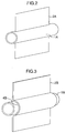
- Figs. 2 and 3 are perspective views showing a partial configuration of a heat transfer tube forming an ice making heat exchanger used for the air conditioner.
- a refrigerating cycle is operated by using midnight electric power mainly at night to store cold heat as ice, and this cold heat is used for air conditioning in the daytime.
- a heat transfer tube 1 in the ice thermal storage tank 5 as an evaporator of refrigerating cycle, a low-temperature, low-pressure cooling medium is caused to flow in a heat exchanger contained in a water tank to make ice on the surface thereof, whereby cold heat is stored.
- the medium passes through a compressor 12, an outdoor heat exchanger 13, which is a condenser, an expansion valve 18A whose opening degree is controlled, the heat transfer tube 1 in the ice thermal storage tank 5, used as an evaporator, and a valve 19, and returns to the compressor 12 through the compressor 12 and the heat exchanger 13.
- the ice generated on the surface has a tube shape whose cross section is substantially circular as shown in Fig. 20, and an unused portion 20 where ice is not made is produced undesirably between the ices 32 generated by the adjacent heat transfer tubes 31 above and below and to the left and right.
- the ice packing factor volume of ice/total water quantity
- ice 32 with a thickness of 60 to 70 mm must be made on the surface of the heat transfer tube 31.
- a thermal resistance from the heat transfer surface to the ice generation surface increases, so that the completion of ice making requires a long period of time.
- the ices 32 growing from the adjacent heat transfer tube 31 confines water in the unused portion 20 so that the water is cut off from escape. Subsequently, therefore, the water in the unused portion 20 freezes and expands, so that there is the possibility of breaking the heat transfer tube 31.
- a plate-shaped ice making heat exchanger is used in the ice thermal storage tank of the ice thermal storage type air conditioner of an internal melt type.
- the heat transfer tube 1 has a pipe shape, and a plate-shaped fin 2 is provided on the heat transfer tube 1.
- the installation direction of the fin 2 is vertical, and a plurality of rows of heat transfer tubes 1 and the fins 2 are arranged.
- an inlet-side header 22 and an outlet-side header 23 are arranged above the ice thermal storage tank 5 so that they are not submerged in the water. Thereby, a heat transfer tube 3 can be inserted from the upper part of the ice thermal storage tank 5, so that the manufacturing property is increased. Since the inlet-side header 22 and an outlet-side header 23 are not submerged in the water, the ice packing factor can be increased. Further, since the confinement of water in the unused portion can be prevented at the time of excessive icing time, the breakage of the heat transfer tube 1 can be avoided.
- the ice packing factor is about 53% when the water level height is 1.21 m.
- the heat transfer tubes 1 provided with a plate-shaped fin 2 in accordance with this embodiment are filled into the ice thermal storage tank of the same size with a pitch of a plurality of rows, that is, a pitch between the plates being 25 mm (10 mm on both surfaces of the plate-shaped fin 2), the ice packing factor can be increased to about 84% with the same water level height.
- the condenser in the ice thermal storage tank 5 has a high pressure, so that the pressure resistance becomes an essential condition.
- the heat transfer tube 1 in accordance with this embodiment has a pipe shape in which the flow path for refrigerant is circular, and has a configuration such that this pipe shape is a skeleton, it is highly pressure-resisting, so that the reliability can be increased even when a non-azeotropic mixture refrigerant, a natural refrigerant, or the like are used.
- the heat transfer tube 1 is used as the ice making heat exchanger for the ice thermal storage type air conditioner, ice is made with a thermal resistance proportional to the thickness of ice, so that the temperature of the refrigerant in the heat transfer tube 1 need not be made low like the conventional ice thermal storage type air conditioner. Therefore, the coefficient of performance (COP) of the refrigerating cycle can be made high, and the electric power consumed before a specified quantity of ice making is reached can be kept low.
- COP coefficient of performance
- the plate-shaped fin 2 can be manufactured easily by pressing or other methods, the heat exchanger is simplified, the manufacture is easy, and the cost can be kept low.
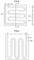
- Fig. 3 is a configuration view showing another embodiment of the heat transfer tube 1A shown in Fig. 2.
- a plate forming the fin 2B is provided with a semicircular concave portion 4B along the outside shape of the heat transfer tube 1B at a location where the plate comes into contact with the tube 1B, by which the heat transfer tube 1B is fixed.
- the contact surface between the heat transfer tube 1B and the fin 2B is increased, so that heat can be transferred more rapidly between the refrigerant flowing in the heat transfer tube 1B and the water (or the ice) outside of the heat transfer tube 1B.
- Figs. 4 and 5 are configuration views showing other embodiments of the heat transfer tube shown in Fig. 2.
- the fin 2C, 2D that is larger than the area occupied by one side of a pipe-shaped heat transfer tube 1C, 1D that lies in the zigzag line on one plane.
- Fig. 4 shows an embodiment of a zigzag tube whose straight pipe portion is horizontal
- Fig. 5 shows an embodiment of a zigzag tube whose straight pipe portion is vertical.
- the fin serves functions of not only increasing the ice making performance but also increasing the rigidity of the heat transfer tube. Therefore, there is no need for providing a support member etc. for the heat transfer tube, so that the structure of heat exchanger can be simplified.
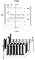
- Fig. 6 is a configuration view showing another embodiment of the heat transfer tube shown in Fig. 4.
- a plate forming the fin 2E is provided with the concave portion 4E along the outside shape of the heat transfer tube 1E at a location where the plate comes into contact with the tube 1E, by which the heat transfer tube 1E is fixed.
- both performances of heat transfer property and rigidity can further be enhanced as compared with the embodiments shown in Figs. 4 and 5.
- Fig. 8 is a configuration view showing another embodiment of the heat transfer tube shown in Fig. 6.
- the fin 2F that covers the straight pipe portions excluding bent portions 7 is joined to one side of a heat transfer tube 1F that lies in the zigzag line on one plane. Therefore, when the concave portion 4 shown in Fig. 6, which is provided to join the heat transfer tube 1 to the fin 2F, is formed, the manufacture is made easy because the curved portions are omitted, which is advantageous in further reducing the cost.
- the joint portions for assembling the heat transfer tubes shown in Fig. 10 together are arranged above the water level of the ice thermal storage tank 5. Thereby, troubles caused by improper joining of the joint portions, leakage of the refrigerant in the refrigerating cycle due to corrosion, or entrance of water into the cycle can be prevented, so that the reliability can be increased further.
- Fig. 18 is a configuration view showing another embodiment of a method for fixing the fin to the heat transfer tube.
- the heat transfer tubes 1P are arranged more densely at both end portions of plate than at the central portion.
- the cross section of ice 11 easily has a streamline shape such as to be thinner at both ends due to natural convection of surrounding water.
- ice 11 can be made more easily at both ends because cold heat is distributed densely to both end portions of the plate. Therefore, the apparent cross-sectional thickness of the ice 11 can be made uniform, so that the space factor at the local portions at the upper and lower parts of the ice thermal storage tank can be increased.
- Fig. 19 is a configuration view showing another embodiment of the heat transfer tube shown in Fig. 2.
- the half peripheral surface of the outside surface of the heat transfer tube 1Q is fixed by the end portion of the plate-shaped fin 2Q from two directions so as to be wrapped.
- the contact area between the heat transfer tube 1Q and the fin 2Q can be increased, and therefore heat is transferred to the fin 2Q more rapidly, so that the ice making time can be shortened when a specified quantity of ice is made.
- the plate-shaped fin is provided, and a plurality of rows of heat transfer tubes and fins are arranged, a space between the heat transfer tubes can be used effectively, so that the ice packing factor can be increased. Also, since the fin is installed vertically, the convection of water in the ice thermal storage tank is accelerated at the time of ice making, so that the breakage of the heat transfer tube can be prevented. Therefore, an ice thermal storage type air conditioner and an ice thermal storage tank can be provided which have improved reliability even when a non-azeotropic mixture refrigerant, a natural refrigerant, or the like is used.
- the heat transfer tube is in a pipe shape of a circular cross section having an outside diameter of 7 to 9 mm, the heat transfer tube is highly pressure-resisting even when a non-azeotropic mixture refrigerant, a natural refrigerant, or the like is used. Since the plate-shaped fins having a thickness of 0.3 to 1.0 mm are laminated at intervals of 10 to 50 mm, an ice thermal storage type air conditioner and an ice thermal storage tank can be provided in which a space in the ice thermal storage tank is used effectively, and thereby the ice packing factor is increased to about 80 to 90%.
Abstract
Description
- The present invention relates to an ice thermal storage type air conditioner in which ice making or thawing is effected by causing a refrigerant to flow in a heat transfer tube provided in an ice thermal storage tank and, more particularly, to an ice thermal storage type air conditioner suitable to increase the productivity of the ice thermal storage tank.
- Conventionally, a technology has been known in which fins are provided so as to fill a clearance between heat transfer tubes forming a heat exchanger in the ice thermal storage tank, and a space that has not been used effectively for ice making is used, by which the ice packing factor is increased. Such a technology has been disclosed in JP-A-7-332711, for example. Also, JP-A-64-10081 has disclosed a technology in which a panel type ice making coil is filled in an ice thermal storage tank so that ice is made into a panel shape, by which water is prevented from being confined in the process of ice making, and the breakage of a heat transfer tube is prevented.
- In the aforementioned prior art described in JP-A-7-332711, because the fins are provided in the horizontal direction of the heat transfer tube, the convection of water is hindered in the ice thermal storage tank at the time of ice making. Therefore, the confinement of water occurs, so that there is the possibility that the confined ice freezes at the time of icing and expands, resulting in the breakage of the heat transfer tube.
- Also, the aforementioned prior art described in JP-A-64-10081 proposes an ice thermal storage type air conditioner opposed to an external melt type in which air conditioning is performed by circulating water at the time of thawing. For the ice thermal storage type air conditioner of a complete internal melt type in which the ice thermal storage tank is handled as a part of condenser at the time of thawing, the heat transfer tube of an ice making heat exchanger also has a high pressure. For the ice thermal storage type air conditioner using a non-azeotropic mixture refrigerant, a stronger pressure-resisting heat transfer tube is needed. For the panel type ice making coil, improper joining and corrosion of the joint portion, leakage of refrigerant, or entrance of water into a refrigerating cycle must be considered.
- Further, the panel type ice making coil must be formed specially, so that the coil of this type cannot be said to be suitable for the decrease in cost. Further, it must be manufactured from the beginning so as to match the size of the ice thermal storage tank, so that there is a problem in terms of common use and flexibility, etc.
- The present invention has been made to solve the problems with the aforementioned prior arts, and an object thereof is to provide an ice thermal storage tank and an ice thermal storage type air conditioner, in which the ice packing factor is increased, the leakage of refrigerant or the entrance of water into the refrigerating cycle is prevented, the reliability is enhanced even when a non-azeotropic mixture refrigerant, a natural refrigerant, or the like is used, and a low cost is achieved.
- The present invention solves at least one of the aforementioned problems.
- To solve the above problems, the present invention provides an ice thermal storage type air conditioner having an outdoor unit equipped with a compressor and an outdoor heat exchanger, an indoor unit equipped with an indoor heat exchanger and an expansion valve, and an ice thermal storage tank equipped with a heat exchanger therein, comprising: the heat exchanger which is used as a condenser when switching is performed to a refrigerating cycle using accumulated heat; a pipe-shaped heat transfer tube and a plate-shaped fin installed to the heat transfer tube, which form the heat exchanger; and the ice thermal storage tank in which the fin is installed vertically, and a plurality of rows of the heat transfer tubes and the fins are arranged.
- Thus, since the heat transfer tube is in a pipe shape, it is highly pressure-resisting, and there is no fear of leakage of refrigerant. Also, since the plate-shaped fin is provided, a clearance between the heat transfer tubes is filled, and a space that has not been used for ice making can be used effectively. Further, since the plurality of rows of the heat transfer tubes and the fins are arranged, the ice packing factor can be increased. Also, since the fin is installed vertically, the convection of water in the ice thermal storage tank is accelerated at the time of ice making, so that the breakage of the heat transfer tube can be prevented. Further, since the heat transfer tube and the fin have only to be assembled so as to match the size of the ice thermal storage tank, this ice thermal storage type air conditioner is advantageous in common use and flexibility.
- Therefore, the leakage of a refrigerant or the entrance of water into the refrigerating cycle is prevented, and the reliability can be increased even when a non-azeotropic mixture refrigerant, a natural refrigerant, or the like are used.
- Also, in the above mode of the present invention, the heat transfer tube and the fin are arranged from the bottom of the ice thermal storage tank to the vicinity of the top end of the vessel.
- Therefore, the size of the ice thermal storage tank can be used effectively, so that the ice packing factor can further be increased.
- Further, in the above mode of the present invention, the fin has a concave portion which is a semicircular groove, and the heat transfer tube is fixed by the concave portion.
- Therefore, since the fin can be manufactured easily by pressing or other methods, the cost can be kept low.
- Further, in the above mode of the present invention, the heat transfer tube is bent into a bellows shape so that each row of the plurality of rows forms a series, and the fin is provided at a straight pipe portion thereof.
- Further, the present invention provides an ice thermal storage type air conditioner having an outdoor unit equipped with a compressor and an outdoor heat exchanger, an indoor unit equipped with an indoor heat exchanger and an expansion valve, and an ice thermal storage tank equipped with a heat exchanger therein, comprising: the heat exchanger which is used as a condenser when switching is performed to a refrigerating cycle using accumulated heat; a flat-shaped fin which forms the heat exchanger and has a dimension in the height direction ranging from the bottom of the ice thermal storage tank to the vicinity of the top end of the vessel; a pipe-shaped heat transfer tube fixed to the fin; and the ice thermal storage tank in which the fin is installed vertically, and a plurality of fins are laminated in the thickness direction.
- Thus, since the heat transfer tube is in a pipe shape, it is highly pressure-resisting, and there is no fear of leakage of refrigerant. Since the flat-shaped fin has a dimension in the height direction ranging from the bottom of the ice thermal storage tank to the vicinity of the top end of the vessel, fixes the pipe-shaped heat transfer tube, and is installed vertically, a space that has not been used for ice making can be used effectively, and the ice packing factor can be increased. Also, the convection of water in the ice thermal storage tank is accelerated at the time of ice making, so that water is not confined at the time of ice making.
- Further, the present invention provides an ice thermal storage type air conditioner having an outdoor unit equipped with a compressor and an outdoor heat exchanger, an indoor unit equipped with an indoor heat exchanger and an expansion valve, and an ice thermal storage tank equipped with a heat exchanger therein, comprising: a heat transfer tube in a pipe shape of a circular cross section having an outside diameter of 7 to 9 mm; a plate-shaped fin with a thickness of 0.3 to 1.0 mm for fixing the heat transfer tube; and the ice thermal storage tank in which the fin is installed vertically, and the heat transfer tube and the fin are laminated at an interval of 10 to 50 mm, characterized in that ice is made on the surfaces of the heat transfer tube and the fin.
- Since the heat transfer tube is in a pipe shape of a circular cross section having an outside diameter of 7 to 9 mm, it is highly pressure-resisting even when a non-azeotropic mixture refrigerant, a natural refrigerant, or the like are used. Since the plate-shaped fin fixes the heat transfer tube, has a thickness of 0.3 to 1.0 mm, and is laminated at an interval of 10 to 50 mm, the strength of the heat transfer tube can be secured, and the space in the ice thermal storage tank can be used effectively. Also, the ice packing factor can be increased to about 80 to 90%.
- Further, the present invention provides an ice thermal storage tank which stores water therein and is provided with a heat transfer tube through which a refrigerant flows in the water, including an inlet-side header and an outlet-side header provided above the ice thermal storage tank so that they are not submerged in the water; and the heat transfer tube in a pipe shape and a plate-shaped fin provided on the heat transfer tube, the fin being installed vertically, and a plurality of rows of the heat transfer tubes and the fins being arranged.
- Since the inlet-side header and the outlet-side header are provided above the ice thermal storage tank so that they are not submerged in the water, the ice packing factor can be increased still further.
- Further, the present invention provides an ice thermal storage tank which stores water therein and is provided with a heat transfer tube through which a refrigerant flows in the water, including an inlet-side header and an outlet-side header provided above the ice thermal storage tank so that they are not submerged in the water; a flat-shaped fin having a dimension in the height direction ranging from the bottom of the ice thermal storage tank to the vicinity of the top end of the vessel; and the heat transfer tube in a pipe shape fixed to the fin, the fin being installed vertically, and a plurality of the fins being laminated in the thickness direction.
- Further, the present invention provides an ice thermal storage tank which stores water therein and is provided with a heat transfer tube through which a refrigerant flows in the water, including an inlet-side header and an outlet-side header provided above the ice thermal storage tank so that they are not submerged in the water; the heat transfer tube in a pipe shape of a circular cross section having an outside diameter of 7 to 9 mm; and a plate-shaped fin with a thickness of 0.3 to 1.0 mm for fixing the heat transfer tube, the fin being installed vertically, and the heat transfer tube and the fin being laminated at an interval of 10 to 50 mm.
- Further, in the above mode of the present invention, the fin has a concave portion which is a semicircular groove, and the heat transfer tube is fixed by the concave portion.
-
- Fig. 1 is a basic schematic view of an ice thermal storage type air conditioner in accordance with one embodiment of the present invention; Fig. 2 is a perspective view showing a partial configuration of a heat transfer tube used for one embodiment shown in Fig. 1; Fig. 3 is a perspective view showing a partial configuration of another embodiment of a heat transfer tube; Fig. 4 is a configuration view of another embodiment of a heat transfer tube and a fin which form a heat exchanger; Fig. 5 is a configuration view of still another embodiment of a heat transfer tube and a fin which form a heat exchanger; Fig. 6 is a configuration view of still another embodiment of a heat transfer tube and a fin which form a heat exchanger; Fig. 7 is a perspective view showing a configuration of another embodiment of an ice thermal storage tank; Fig. 8 is a configuration view of still another embodiment of a heat transfer tube and a fin which form a heat exchanger; Fig. 9 is a configuration view of still another embodiment of a heat transfer tube and a fin which form a heat exchanger; Fig. 10 is a configuration view of still another embodiment of a heat transfer tube and a fin which form a heat exchanger; Fig. 11 is a configuration view of still another embodiment of a heat transfer tube and a fin which form a heat exchanger; Fig. 12 is a configuration view of still another embodiment of an ice thermal storage tank; Fig. 13 is a configuration view of still another embodiment of a heat transfer tube and a fin which form a heat exchanger; Fig. 14 is a configuration view of still another embodiment of a heat transfer tube and a fin which form a heat exchanger; Fig. 15 is a configuration view of still another embodiment of a heat transfer tube and a fin which form a heat exchanger; Fig. 16 is an arrangement view showing a state in which heat transfer tubes and fins in accordance with another embodiment are contained in an ice thermal storage tank; Fig. 17 is a configuration view of still another embodiment of a heat transfer tube and a fin which form a heat exchanger; Fig. 18 is a configuration view of still another embodiment of a heat transfer tube and a fin which form a heat exchanger; Fig. 19 is a configuration view of still another embodiment of a heat transfer tube and a fin which form a heat exchanger; and Fig. 20 is a perspective view showing a state of a conventional heat transfer tube at the time of ice making.
-
- An embodiment of the present invention will now be described with reference to the accompanying drawings.
- Fig. 1 is a basic schematic view of an ice thermal storage type air conditioner in accordance with one embodiment, and Figs. 2 and 3 are perspective views showing a partial configuration of a heat transfer tube forming an ice making heat exchanger used for the air conditioner.
- For the ice thermal storage type air conditioner, a refrigerating cycle is operated by using midnight electric power mainly at night to store cold heat as ice, and this cold heat is used for air conditioning in the daytime. When cold heat is stored in an ice thermal storage tank, by using a
heat transfer tube 1 in the icethermal storage tank 5 as an evaporator of refrigerating cycle, a low-temperature, low-pressure cooling medium is caused to flow in a heat exchanger contained in a water tank to make ice on the surface thereof, whereby cold heat is stored. For this refrigerating cycle, the medium passes through acompressor 12, anoutdoor heat exchanger 13, which is a condenser, anexpansion valve 18A whose opening degree is controlled, theheat transfer tube 1 in the icethermal storage tank 5, used as an evaporator, and avalve 19, and returns to thecompressor 12 through thecompressor 12 and theheat exchanger 13. - When cold heat is used for air conditioning, by using the heat exchanger in the ice
thermal storage tank 5 as a part of a condenser of refrigerating cycle, a high-temperature, high-pressure cooling medium is caused to flow in the heat exchanger to thawice 11 from the ice making surface side of theheat transfer tube 1, whereby cold heat is taken out. - For the conventional
heat transfer tube 31, a copper pipe (outside diameter: about 7 to 9 mm) having a circular cross section that is bent into a bellows shape is used. Therefore, the ice generated on the surface has a tube shape whose cross section is substantially circular as shown in Fig. 20, and anunused portion 20 where ice is not made is produced undesirably between theices 32 generated by the adjacentheat transfer tubes 31 above and below and to the left and right. For this reason, the ice packing factor (volume of ice/total water quantity) is about 65%. In order to increase the ice packing factor,ice 32 with a thickness of 60 to 70 mm must be made on the surface of theheat transfer tube 31. Along with the generation of theice 32, a thermal resistance from the heat transfer surface to the ice generation surface increases, so that the completion of ice making requires a long period of time. - If ice has been made excessively, the
ices 32 growing from the adjacentheat transfer tube 31 confines water in theunused portion 20 so that the water is cut off from escape. Subsequently, therefore, the water in theunused portion 20 freezes and expands, so that there is the possibility of breaking theheat transfer tube 31. - For the ice thermal storage type air conditioner shown in Fig. 1, a plate-shaped ice making heat exchanger is used in the ice thermal storage tank of the ice thermal storage type air conditioner of an internal melt type. The
heat transfer tube 1 has a pipe shape, and a plate-shaped fin 2 is provided on theheat transfer tube 1. The installation direction of thefin 2 is vertical, and a plurality of rows ofheat transfer tubes 1 and thefins 2 are arranged. - Thereupon, the group of the
heat transfer tubes 1 is substantially the same as a type in which plate-shaped ice making heat exchangers that are perpendicular to the bottom surface of the icethermal storage tank 5 are arranged, so that the heat transfer area of theheat transfer tube 1 can be increased, and therefore the quantity of ice making can be increased. If the quantity of ice making is equal, the thickness of ice can be decreased because ice grows on thefin 2 as well, so that the thermal resistance of ice itself can be kept low as compared with the case where only circular tubes are arranged. Further, since the ice substantially has a plate shape, the unused portion decreases, and the ice packing factor can be enhanced. - As shown in Fig. 1, an inlet-
side header 22 and an outlet-side header 23 are arranged above the icethermal storage tank 5 so that they are not submerged in the water. Thereby, a heat transfer tube 3 can be inserted from the upper part of the icethermal storage tank 5, so that the manufacturing property is increased. Since the inlet-side header 22 and an outlet-side header 23 are not submerged in the water, the ice packing factor can be increased. Further, since the confinement of water in the unused portion can be prevented at the time of excessive icing time, the breakage of theheat transfer tube 1 can be avoided. - Specifically, if a zigzag heat exchanger is used in a square type ice thermal storage tank (bottom area: 0.33 m2, top area: 0.39 m2, tank height 1.26 m), the ice packing factor is about 53% when the water level height is 1.21 m. Contrary to this, if the
heat transfer tubes 1 provided with a plate-shapedfin 2 in accordance with this embodiment are filled into the ice thermal storage tank of the same size with a pitch of a plurality of rows, that is, a pitch between the plates being 25 mm (10 mm on both surfaces of the plate-shaped fin 2), the ice packing factor can be increased to about 84% with the same water level height. - For the air conditioner of an internal melt type, when the refrigerating cycle is switched to the cycle in which the heat exchanger in the ice thermal storage tank is used as a part of the condenser at the time of thawing (the time when the stored heat is used), the condenser in the ice
thermal storage tank 5 has a high pressure, so that the pressure resistance becomes an essential condition. However, since theheat transfer tube 1 in accordance with this embodiment has a pipe shape in which the flow path for refrigerant is circular, and has a configuration such that this pipe shape is a skeleton, it is highly pressure-resisting, so that the reliability can be increased even when a non-azeotropic mixture refrigerant, a natural refrigerant, or the like are used. - Further, since the
heat transfer tube 1 is used as the ice making heat exchanger for the ice thermal storage type air conditioner, ice is made with a thermal resistance proportional to the thickness of ice, so that the temperature of the refrigerant in theheat transfer tube 1 need not be made low like the conventional ice thermal storage type air conditioner. Therefore, the coefficient of performance (COP) of the refrigerating cycle can be made high, and the electric power consumed before a specified quantity of ice making is reached can be kept low. - Further, the
heat transfer tube 1 of this embodiment can increase the reliability at the time of high pressures as compared with a plate-type heat exchanger of a joint type in which two plates are joined to form the flow path for the refrigerant. - Further, since the plate-shaped
fin 2 can be manufactured easily by pressing or other methods, the heat exchanger is simplified, the manufacture is easy, and the cost can be kept low. - Further, since the
fin 2 and the pipe-shapedheat transfer tube 1 have only to be assembled to each other, countermeasures for various icethermal storage tank 5 having different sizes and shapes can be taken easily, and the parts can be used commonly. - Also, although the
heat transfer tube 1 installed horizontally (the refrigerant flows in the substantially horizontal direction with respect to the bottom surface of the ice thermal storage tank) is shown in Fig. 1, theheat transfer pipe 1 may be installed vertically with respect to the bottom surface of the ice thermal storage tank. - Fig. 3 is a configuration view showing another embodiment of the
heat transfer tube 1A shown in Fig. 2. In this embodiment, a plate forming thefin 2B is provided with a semicircularconcave portion 4B along the outside shape of theheat transfer tube 1B at a location where the plate comes into contact with thetube 1B, by which theheat transfer tube 1B is fixed. Thereby, the contact surface between theheat transfer tube 1B and thefin 2B is increased, so that heat can be transferred more rapidly between the refrigerant flowing in theheat transfer tube 1B and the water (or the ice) outside of theheat transfer tube 1B. - Figs. 4 and 5 are configuration views showing other embodiments of the heat transfer tube shown in Fig. 2. In these embodiments, the
fin heat transfer tube - Thus, the fin serves functions of not only increasing the ice making performance but also increasing the rigidity of the heat transfer tube. Therefore, there is no need for providing a support member etc. for the heat transfer tube, so that the structure of heat exchanger can be simplified.
- Fig. 6 is a configuration view showing another embodiment of the heat transfer tube shown in Fig. 4. In this embodiment, a plate forming the
fin 2E is provided with theconcave portion 4E along the outside shape of theheat transfer tube 1E at a location where the plate comes into contact with thetube 1E, by which theheat transfer tube 1E is fixed. Thereby, both performances of heat transfer property and rigidity can further be enhanced as compared with the embodiments shown in Figs. 4 and 5. - Fig. 7 is a configuration view of an ice thermal storage tank using the heat transfer tube shown in Fig. 4, 5 or 6. In Fig. 7, an excess fin portion at each end of the heat transfer tube shown in Figs. 4 to 6 is fitted into a
guide portion 6 provided in the internal wall at the side of the icethermal storage tank 5. Therefore, there is no need for specially providing a structural member etc. for supporting each of the heat transfer tubes forming the heat exchanger with a clearance provided therebetween. - Fig. 8 is a configuration view showing another embodiment of the heat transfer tube shown in Fig. 6. In these embodiments, the
fin 2F that covers the straight pipe portions excludingbent portions 7 is joined to one side of aheat transfer tube 1F that lies in the zigzag line on one plane. Therefore, when the concave portion 4 shown in Fig. 6, which is provided to join theheat transfer tube 1 to thefin 2F, is formed, the manufacture is made easy because the curved portions are omitted, which is advantageous in further reducing the cost. - Fig. 9 is a configuration view showing another embodiment of the heat transfer tube shown in Fig. 8. In this embodiment, the
bent portions 7 of theheat transfer tube 1G, which is not covered by thefin 2G, is covered by an insulatingmember 8. Therefore, excessive icing on thebent portions 7 can be avoided. Further, by configuring theheat transfer tube 1G so that thefins 2G are in parallel to each other and perpendicular to the bottom surface of the icethermal storage tank 5, the thermal insulation of the side surface of the icethermal storage tank 5 can also be effected. Although a zigzag tube whose straight pipe portion is horizontal is shown in this embodiment, for a zigzag tube whose straight pipe portion is vertical, thebent portions 7 are arranged at the bottom and top portions of the icethermal storage tank 5, so that the insulatingmember 8 can be used for insulating the bottom and top portions of the icethermal storage tank 5. - Fig. 10 is a configuration view showing another embodiment of the heat transfer tube shown in Fig. 2. In this embodiment, on one surface of a series of U-shaped
heat transfer tube 1H including onebent portion 7 of theheat transfer tube 1H, a plate-shapedfin 2H is provided to cover it. As shown in Fig. 11, a heat exchanger can be assembled by combining these heat transfer tubes by mountingbents 9 in accordance with the size of various icethermal storage tanks 5. Therefore, the heat exchanger parts can be used commonly for the icethermal storage tanks 5 of various sizes. - Also, as shown in Fig. 12, the joint portions for assembling the heat transfer tubes shown in Fig. 10 together are arranged above the water level of the ice
thermal storage tank 5. Thereby, troubles caused by improper joining of the joint portions, leakage of the refrigerant in the refrigerating cycle due to corrosion, or entrance of water into the cycle can be prevented, so that the reliability can be increased further. - Fig. 13 is a configuration view of another embodiment in which the combination of the heat transfer tubes shown in Fig. 10 is changed. In this embodiment, a plurality of heat transfer tubes, in which the
bent portions 7 are not covered by the plate-shaped fin 2J1 and are exposed, are installed and joined by the mountingbents 9, and are newly covered by a fin 2J2 that covers only the exposedbent portions 7. Thereby, excessive icing on thebent portion 7 can be prevented. Also, thefin 2 for thebent portion 7, which requires fabrication of complex shape such as drawing matching the bent shape of the heat transfer tube, can be fabricated continuously by being separated from the straight pipe portion, so that the productivity can also be improved. - Fig. 14 is a configuration view showing another embodiment of the heat transfer tube shown in Fig. 2. In this embodiment, a band-shaped
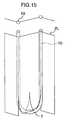
fin 2K is fixed at least by being touched so as to be held between a plurality of paths of straight pipe portions or all paths of straight pipe portions of a series of heat transfer tubes. If the band-shapedfin 2K is configured so that a plurality of fins having a width smaller than the length of the straight pipe portion of the heat transfer tube are combined, countermeasures can be taken easily for the icethermal storage tank 5 with a different depth by changing the length of the straight pipe portion of the heat transfer tube and the number of the band-shapedfins 2K. Therefore, this embodiment is advantageous in decreasing the cost by the common use of parts. - Fig. 15 is a configuration view showing another embodiment of the heat transfer tube shown in Fig. 10. In this embodiment, a
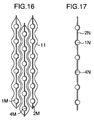
valley portion 10 formed when thefin 2L itself is bent is substituted for the concave portion 4 of the fin in which the pipe is accommodated. At thebent portion 7, a cut is made in thefin 2L and thebent portion 7 is put between the fins. This embodiment is advantageous in decreasing the cost. - Fig. 16 shows another embodiment of an arrangement of the
heat transfer tubes 1M in the icethermal storage tank 5. In this embodiment, theheat transfer tubes 1M are arranged in a zigzag form in the height direction of the icethermal storage tank 5. Thereby, the number of filled heat transfer tubes in the thickness direction of thefin 2M can be increased as compared with an arrangement in a checkerboard form, so that the packing factor ofice 11 can be increased. - Fig. 17 is a configuration view showing another embodiment of a method for fixing the
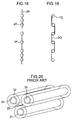
fin 2N to theheat transfer tube 1N. In this embodiment, theconcave portions 4N of the plate-shapedfin 2N for fixing theheat transfer tube 1N are formed alternately on the surface side and the back side of thefin 2N, by which the surface to which theheat transfer tube 1N is fixed is made alternate. Thereby, the deformation caused by fabrication when theconcave portion 4N is formed and the weight distribution of theheat transfer tubes 1N can be made uniform apparently, so that the rigidity of the heat exchanger can be increased. - Fig. 18 is a configuration view showing another embodiment of a method for fixing the fin to the heat transfer tube. In this embodiment, when the straight pipe portion of the
heat transfer tube 1P is installed horizontally, theheat transfer tubes 1P are arranged more densely at both end portions of plate than at the central portion. When the pipes are arranged uniformly, at the time of ice making, the cross section ofice 11 easily has a streamline shape such as to be thinner at both ends due to natural convection of surrounding water. According to this embodiment,ice 11 can be made more easily at both ends because cold heat is distributed densely to both end portions of the plate. Therefore, the apparent cross-sectional thickness of theice 11 can be made uniform, so that the space factor at the local portions at the upper and lower parts of the ice thermal storage tank can be increased. - Fig. 19 is a configuration view showing another embodiment of the heat transfer tube shown in Fig. 2. In this embodiment, the half peripheral surface of the outside surface of the
heat transfer tube 1Q is fixed by the end portion of the plate-shapedfin 2Q from two directions so as to be wrapped. Thereby, the contact area between theheat transfer tube 1Q and thefin 2Q can be increased, and therefore heat is transferred to thefin 2Q more rapidly, so that the ice making time can be shortened when a specified quantity of ice is made. - A clearance (pipe pitch) between the straight pipe portions of the
heat transfer tubes 1Q should be 20 to 400 times the plate thickness of thefin 2Q in terms of ice making capability, preferably being 30 to 50 times. - According to the present invention, since the heat transfer tube is in a pipe shape, and therefore is highly pressure-resisting, the plate-shaped fin is provided, and a plurality of rows of heat transfer tubes and fins are arranged, a space between the heat transfer tubes can be used effectively, so that the ice packing factor can be increased. Also, since the fin is installed vertically, the convection of water in the ice thermal storage tank is accelerated at the time of ice making, so that the breakage of the heat transfer tube can be prevented. Therefore, an ice thermal storage type air conditioner and an ice thermal storage tank can be provided which have improved reliability even when a non-azeotropic mixture refrigerant, a natural refrigerant, or the like is used.
- Also, according to the present invention, since the heat transfer tube is in a pipe shape, there is no fear of leakage of refrigerant. Since the flat-shaped fin, having a dimension in the height direction ranging from the bottom of the ice thermal storage tank to the vicinity of the top end of the vessel, is installed vertically, an ice thermal storage type air conditioner and an ice thermal storage tank can be provided in which the convection of water in the ice thermal storage tank is accelerated at the time of ice making, and water is not confined at the time of ice making.
- Further, according to the present invention, since the heat transfer tube is in a pipe shape of a circular cross section having an outside diameter of 7 to 9 mm, the heat transfer tube is highly pressure-resisting even when a non-azeotropic mixture refrigerant, a natural refrigerant, or the like is used. Since the plate-shaped fins having a thickness of 0.3 to 1.0 mm are laminated at intervals of 10 to 50 mm, an ice thermal storage type air conditioner and an ice thermal storage tank can be provided in which a space in the ice thermal storage tank is used effectively, and thereby the ice packing factor is increased to about 80 to 90%.
Claims (10)
- An ice thermal storage type air conditioner having an outdoor unit equipped with a compressor and an outdoor heat exchanger, an indoor unit equipped with an indoor heat exchanger and an expansion valve, and an ice thermal storage tank equipped with a heat exchanger therein, comprising:said heat exchanger which is used as a condenser when switching is performed to a refrigerating cycle using accumulated heat;a pipe-shaped heat transfer tube and a plate-shaped fin installed to said heat transfer tube, which form said heat exchanger; andsaid ice thermal storage tank in which said fin is installed vertically, and a plurality of rows of said heat transfer tubes and said fins are arranged.
- The ice thermal storage type air conditioner according to claim 1, wherein said heat transfer tube and fin are arranged from the bottom of said ice thermal storage tank to the vicinity of the top end of the vessel.
- The ice thermal storage type air conditioner according to claim 1, wherein said fin has a concave portion which is a semicircular groove, and said heat transfer tube is fixed by said concave portion.
- The ice thermal storage type air conditioner according to claim 1, wherein said heat transfer tube is bent into a bellows shape so that each row of said plurality of rows forms a series, and said fin is provided at a straight pipe portion thereof.
- An ice thermal storage type air conditioner having an outdoor unit equipped with a compressor and an outdoor heat exchanger, an indoor unit equipped with an indoor heat exchanger and an expansion valve, and an ice thermal storage tank equipped with a heat exchanger therein, comprising:said heat exchanger which is used as a condenser when switching is performed to a refrigerating cycle using accumulated heat;a flat-shaped fin which forms said heat exchanger and has a dimension in the height direction ranging from the bottom of said ice thermal storage tank to the vicinity of the top end of the vessel;a pipe-shaped heat transfer tube fixed to said fin; andsaid ice thermal storage tank in which said fin is installed vertically, and a plurality of fins are laminated in the thickness direction.
- An ice thermal storage type air conditioner having an outdoor unit equipped with a compressor and an outdoor heat exchanger, an indoor unit equipped with an indoor heat exchanger and an expansion valve, and an ice thermal storage tank equipped with a heat exchanger therein, comprising:a heat transfer tube in a pipe shape of a circular cross section having an outside diameter of 7 to 9 mm;a plate-shaped fin with a thickness of 3 to 10 mm for fixing said heat transfer tube; andsaid ice thermal storage tank in which said fin is installed vertically, and said heat transfer tube and said fin are laminated at an interval of 10 to 50 mm,
characterized in that ice is made on the surfaces of said heat transfer tube and said fin. - An ice thermal storage tank which stores water therein and is provided with a heat transfer tube through which a refrigerant flows in the water, including an inlet-side header and an outlet-side header provided above said ice thermal storage tank so that they are not submerged in the water; and said heat transfer tube in a pipe shape and a plate-shaped fin provided on said heat transfer tube, said fin being installed vertically, and a plurality of rows of said heat transfer tubes and said fins being arranged.
- An ice thermal storage tank which stores water therein and is provided with a heat transfer tube through which a refrigerant flows in the water, including an inlet-side header and an outlet-side header provided above said ice thermal storage tank so that they are not submerged in the water; a flat-shaped fin having a dimension in the height direction ranging from the bottom of said ice thermal storage tank to the vicinity of the top end of the vessel; and said heat transfer tube in a pipe shape fixed to said fin, said fin being installed vertically, and a plurality of said fins being laminated in the thickness direction.
- An ice thermal storage tank which stores water therein and is provided with a heat transfer tube through which a refrigerant flows in the water, including an inlet-side header and an outlet-side header provided above said ice thermal storage tank so that they are not submerged in the water; said heat transfer tube in a pipe shape of a circular cross section having an outside diameter of 7 to 9 mm; and a plate-shaped fin with a thickness of 0.3 to 1.0 mm for fixing said heat transfer tube, said fin being installed vertically, and said heat transfer tube and said fin being laminated at an interval of 10 to 50 mm.
- The ice thermal storage tank according to any one of claims 7 to 9, wherein said fin has a concave portion which is a semicircular groove, and said heat transfer tube is fixed by said concave portion.
Applications Claiming Priority (2)
| Application Number | Priority Date | Filing Date | Title |
|---|---|---|---|
| JP26271298 | 1998-09-17 | ||
| JP10262712A JP2000088297A (en) | 1998-09-17 | 1998-09-17 | Ice heat storage type air-conditioning device and ice heat storage tank |
Publications (2)
| Publication Number | Publication Date |
|---|---|
| EP0987502A2 true EP0987502A2 (en) | 2000-03-22 |
| EP0987502A3 EP0987502A3 (en) | 2002-06-12 |
Family
ID=17379553
Family Applications (1)
| Application Number | Title | Priority Date | Filing Date |
|---|---|---|---|
| EP99118268A Withdrawn EP0987502A3 (en) | 1998-09-17 | 1999-09-14 | Ice thermal storage type air conditioner and ice thermal storage tank |
Country Status (3)
| Country | Link |
|---|---|
| US (1) | US6253567B1 (en) |
| EP (1) | EP0987502A3 (en) |
| JP (1) | JP2000088297A (en) |
Cited By (7)
| Publication number | Priority date | Publication date | Assignee | Title |
|---|---|---|---|---|
| WO2008011846A1 (en) * | 2006-07-28 | 2008-01-31 | Webasto Ag | Cold and/or heat store |
| CN101788172B (en) * | 2009-01-22 | 2012-07-25 | 珠海格力电器股份有限公司 | Energy-storage air conditioning unit and working method thereof |
| GB2489011A (en) * | 2011-03-16 | 2012-09-19 | Green Structures Ltd | Thermal energy store |
| EP2623896A4 (en) * | 2010-09-30 | 2016-03-09 | Panasonic Corp | Heat storage device and air conditioner with the heat storage device |
| WO2018199783A1 (en) * | 2017-04-24 | 2018-11-01 | Mar-Bud Społka Z Ograniczoną Odpowiedzialnością | The device for manufacturing and storing ice |
| TWI658238B (en) * | 2016-08-12 | 2019-05-01 | 國立勤益科技大學 | Split energy storage system and method |
| EP3845851A4 (en) * | 2018-08-27 | 2021-09-01 | Mitsubishi Electric Corporation | Heat exchanger, heat exchanger unit, and refrigeration cycle device |
Families Citing this family (35)
| Publication number | Priority date | Publication date | Assignee | Title |
|---|---|---|---|---|
| KR100363969B1 (en) * | 2000-02-11 | 2002-12-11 | 엘지전자 주식회사 | Evaporator for Refrigerator And Method for Manufacturing Header of Evaporator |
| JP2001227793A (en) * | 2000-02-14 | 2001-08-24 | Hitachi Ltd | Ice storage type heat source unit |
| JP2002250547A (en) * | 2000-12-22 | 2002-09-06 | Sekisui Plant Systems Co Ltd | Ice storage device |
| US6543245B1 (en) * | 2001-11-08 | 2003-04-08 | Thermo King Corporation | Multi-temperature cold plate refrigeration system |
| US20050209547A1 (en) * | 2002-06-06 | 2005-09-22 | Burbank Jeffrey H | Last-chance quality check and/or air/pathogen filter for infusion systems |
| WO2004062710A2 (en) | 2003-01-07 | 2004-07-29 | Nxstage Medical Inc. | Batch filtration system for preparation of sterile replacement fluid for renal therapy |
| US9700663B2 (en) * | 2005-01-07 | 2017-07-11 | Nxstage Medical, Inc. | Filtration system for preparation of fluids for medical applications |
| US20080210606A1 (en) | 2004-01-07 | 2008-09-04 | Jeffrey Burbank | Filtration System Preparation of Fluids for Medical Applications |
| EP1615616A2 (en) * | 2003-04-14 | 2006-01-18 | The Procter & Gamble Company | Anhydrous, transfer-resistant cosmetic lip compositions |
| WO2007034939A1 (en) * | 2005-09-26 | 2007-03-29 | Hara Tech Corporation | Thermal converter for condensation and refrigeration system using the same |
| US7681410B1 (en) * | 2006-02-14 | 2010-03-23 | American Power Conversion Corporation | Ice thermal storage |
| JP2007263431A (en) * | 2006-03-28 | 2007-10-11 | Sanyo Electric Co Ltd | Manufacturing method of transient critical refrigerating cycle apparatus |
| US8469331B2 (en) * | 2006-04-07 | 2013-06-25 | Nxstage Medical, Inc. | Filtration system for preparation of fluids for medical applications |
| JP4231518B2 (en) * | 2006-10-24 | 2009-03-04 | トヨタ自動車株式会社 | Heat exchanger |
| US7891575B2 (en) * | 2006-11-03 | 2011-02-22 | Sami Samuel M | Method and apparatus for thermal storage using heat pipes |
| US7671567B2 (en) * | 2007-06-15 | 2010-03-02 | Tesla Motors, Inc. | Multi-mode charging system for an electric vehicle |
| US7854131B2 (en) * | 2008-04-16 | 2010-12-21 | The Boeing Company | Thermal buffer system |
| US8146375B2 (en) * | 2009-03-10 | 2012-04-03 | Thermo King Corporation | Hydrocooler with thermal storage |
| US7905110B2 (en) * | 2009-04-02 | 2011-03-15 | Daniel Reich | Thermal energy module |
| US20110079025A1 (en) * | 2009-10-02 | 2011-04-07 | Thermo King Corporation | Thermal storage device with ice thickness detection and control methods |
| US20110100583A1 (en) * | 2009-10-29 | 2011-05-05 | Freund Sebastian W | Reinforced thermal energy storage pressure vessel for an adiabatic compressed air energy storage system |
| US8136368B2 (en) * | 2010-07-19 | 2012-03-20 | Daniel Reich | Modular evaporator and thermal energy storage system for chillers |
| JP2013088050A (en) * | 2011-10-19 | 2013-05-13 | Mitsubishi Plastics Inc | Latent heat storage tank and hot water supply system |
| JP2013088049A (en) * | 2011-10-19 | 2013-05-13 | Mitsubishi Plastics Inc | Latent heat storage tank and hot water supply system |
| JP6132015B2 (en) | 2013-05-17 | 2017-05-24 | 株式会社Ihi | Heat storage system |
| KR102236776B1 (en) * | 2014-09-05 | 2021-04-06 | 삼성전자주식회사 | An evaporator, an refrigerator using the evaporator and a method for controlling the refrigerator |
| WO2016154464A1 (en) * | 2015-03-24 | 2016-09-29 | Evapco, Inc. | Thermal storage ice breaker apparatus |
| US20160363387A1 (en) * | 2015-06-12 | 2016-12-15 | Hamilton Sundstrand Space Systems International, Inc. | Phase-change material heat exchanger |
| CN105805872A (en) * | 2016-04-26 | 2016-07-27 | 珠海格力电器股份有限公司 | Control method of ice storage air-conditioning system and ice storage air-conditioning system |
| IL248304B (en) * | 2016-10-10 | 2021-07-29 | Magen Eco Energy A C S Ltd | Heat exchanger and module thereof |
| JP7001917B2 (en) * | 2017-03-16 | 2022-01-20 | ダイキン工業株式会社 | Heat exchanger with heat transfer tube unit |
| US9989271B1 (en) | 2017-08-14 | 2018-06-05 | Calvin Becker | Air conditioning with thermal storage |
| WO2021021993A1 (en) * | 2019-08-01 | 2021-02-04 | Weller Ice, LLC | Ice machine for an ice-based thermal storage system |
| GB2601995B (en) * | 2020-12-08 | 2023-09-06 | Dyson Technology Ltd | Heat storage device |
| PL436607A1 (en) * | 2020-12-31 | 2021-10-25 | Mar-Bud Spółka Z Ograniczoną Odpowiedzialnością Budownictwo Spółka Komandytowa | Heat accumulator system for refrigeration and air conditioning systems |
Citations (2)
| Publication number | Priority date | Publication date | Assignee | Title |
|---|---|---|---|---|
| JPS6410081A (en) | 1987-06-30 | 1989-01-13 | Nippon Kokan Kk | Cold and hot heat extracting method and device in ice cold accumulator |
| JPH07332711A (en) | 1994-06-06 | 1995-12-22 | Hitachi Ltd | Ice thermal storage unit |
Family Cites Families (14)
| Publication number | Priority date | Publication date | Assignee | Title |
|---|---|---|---|---|
| JPS50153442A (en) * | 1974-05-31 | 1975-12-10 | ||
| US4434843A (en) * | 1978-04-17 | 1984-03-06 | International Environmental Manufacturing Co. | Heat exchanger apparatus |
| JPS55105194A (en) * | 1979-02-07 | 1980-08-12 | Hitachi Ltd | Heat-exchanger |
| FR2529309B1 (en) * | 1982-06-24 | 1987-07-10 | Comp Generale Electricite | WATER-AIR CONVECTOR WITH CHIMNEY EFFECT FOR HEATING A PREMISES |
| US5259214A (en) * | 1990-11-08 | 1993-11-09 | Mitsubishi Denki Kabushiki Kaisha | Air conditioning system |
| JPH04356637A (en) * | 1991-06-03 | 1992-12-10 | Nkk Corp | Method and apparatus for taking out cold heat in ice cold heat accumulating device |
| JPH05157475A (en) * | 1991-12-11 | 1993-06-22 | Daikin Ind Ltd | Ice cold accumulator |
| ES2065808B1 (en) * | 1992-05-06 | 1996-12-16 | Kobol Sa | HEAT EXCHANGER AND ITS MANUFACTURING PROCESS. |
| JP3260418B2 (en) * | 1992-06-15 | 2002-02-25 | 東京電力株式会社 | Thermal storage type air conditioner |
| JPH07260212A (en) * | 1994-03-25 | 1995-10-13 | Daikin Ind Ltd | Ice heat accumulating device |
| US5649431A (en) * | 1994-11-15 | 1997-07-22 | Tdindustries, Inc. | Thermal storage cooling system |
| US5540276A (en) * | 1995-01-12 | 1996-07-30 | Brazeway, Inc. | Finned tube heat exchanger and method of manufacture |
| JPH08261518A (en) * | 1995-03-23 | 1996-10-11 | Daikin Ind Ltd | Ice heat accumulating device |
| US5535820A (en) * | 1995-07-18 | 1996-07-16 | Blissfield Manufacturing Company | Method for assembling a heat exchanger |
-
1998
- 1998-09-17 JP JP10262712A patent/JP2000088297A/en active Pending
-
1999
- 1999-09-14 EP EP99118268A patent/EP0987502A3/en not_active Withdrawn
- 1999-09-16 US US09/396,878 patent/US6253567B1/en not_active Expired - Fee Related
Patent Citations (2)
| Publication number | Priority date | Publication date | Assignee | Title |
|---|---|---|---|---|
| JPS6410081A (en) | 1987-06-30 | 1989-01-13 | Nippon Kokan Kk | Cold and hot heat extracting method and device in ice cold accumulator |
| JPH07332711A (en) | 1994-06-06 | 1995-12-22 | Hitachi Ltd | Ice thermal storage unit |
Cited By (8)
| Publication number | Priority date | Publication date | Assignee | Title |
|---|---|---|---|---|
| WO2008011846A1 (en) * | 2006-07-28 | 2008-01-31 | Webasto Ag | Cold and/or heat store |
| CN101788172B (en) * | 2009-01-22 | 2012-07-25 | 珠海格力电器股份有限公司 | Energy-storage air conditioning unit and working method thereof |
| EP2623896A4 (en) * | 2010-09-30 | 2016-03-09 | Panasonic Corp | Heat storage device and air conditioner with the heat storage device |
| GB2489011A (en) * | 2011-03-16 | 2012-09-19 | Green Structures Ltd | Thermal energy store |
| GB2489069A (en) * | 2011-03-16 | 2012-09-19 | Green Structures Ltd | Thermal energy store |
| TWI658238B (en) * | 2016-08-12 | 2019-05-01 | 國立勤益科技大學 | Split energy storage system and method |
| WO2018199783A1 (en) * | 2017-04-24 | 2018-11-01 | Mar-Bud Społka Z Ograniczoną Odpowiedzialnością | The device for manufacturing and storing ice |
| EP3845851A4 (en) * | 2018-08-27 | 2021-09-01 | Mitsubishi Electric Corporation | Heat exchanger, heat exchanger unit, and refrigeration cycle device |
Also Published As
| Publication number | Publication date |
|---|---|
| JP2000088297A (en) | 2000-03-31 |
| US6253567B1 (en) | 2001-07-03 |
| EP0987502A3 (en) | 2002-06-12 |
Similar Documents
| Publication | Publication Date | Title |
|---|---|---|
| US6253567B1 (en) | Ice thermal storage type air conditioner and ice thermal storage tank | |
| KR101137031B1 (en) | Cold-storage heat exchanger | |
| US6101821A (en) | Ice thermal storage coil systems and methods | |
| JP5768480B2 (en) | Cold storage heat exchanger | |
| CN103930747A (en) | Plate fin-and-tube heat exchanger, and refrigeration and air-conditioning system with same | |
| JP2005055108A (en) | Heat exchanger | |
| JP3353692B2 (en) | Ice storage type air conditioner and ice storage tank | |
| JPH0345300B2 (en) | ||
| JPH08247678A (en) | Heat-exchanger made of aluminum | |
| JPH0245945B2 (en) | ||
| JP3100074B2 (en) | Cooling system | |
| JPH09318195A (en) | Laminated evaporator | |
| KR101468912B1 (en) | Rear wall condenser for domestic refrigerators and freezers | |
| JPH0833287B2 (en) | Aluminum condenser for air conditioner | |
| JPH0345302B2 (en) | ||
| JPH0762596B2 (en) | Aluminum condenser for air conditioner | |
| JPH0345301B2 (en) | ||
| JPH0332944Y2 (en) | ||
| JP2004150710A (en) | Refrigerant evaporator and its manufacturing method | |
| JP2004028470A (en) | Heat exchanger | |
| JP4633967B2 (en) | Ice thermal storage air conditioner | |
| JPH08261518A (en) | Ice heat accumulating device | |
| KR200306466Y1 (en) | Fin Tube installed Energy Storage-and-Recovery Device using Latent Heat of Fusion of Water and Air-Conditioning System with the Device | |
| JP2006132847A (en) | Heat exchanger, and outdoor unit for air conditioner equipped with the same | |
| JPH06137616A (en) | Heat exchange coil for ice heat storage tank |
Legal Events
| Date | Code | Title | Description |
|---|---|---|---|
| PUAI | Public reference made under article 153(3) epc to a published international application that has entered the european phase |
Free format text: ORIGINAL CODE: 0009012 |
|
| 17P | Request for examination filed |
Effective date: 19990914 |
|
| AK | Designated contracting states |
Kind code of ref document: A2 Designated state(s): AT BE CH CY DE DK ES FI FR GB GR IE IT LI LU MC NL PT SE |
|
| AX | Request for extension of the european patent |
Free format text: AL;LT;LV;MK;RO;SI |
|
| PUAL | Search report despatched |
Free format text: ORIGINAL CODE: 0009013 |
|
| AK | Designated contracting states |
Kind code of ref document: A3 Designated state(s): AT BE CH CY DE DK ES FI FR GB GR IE IT LI LU MC NL PT SE |
|
| AX | Request for extension of the european patent |
Free format text: AL;LT;LV;MK;RO;SI |
|
| AKX | Designation fees paid |
Designated state(s): DE FR GB |
|
| STAA | Information on the status of an ep patent application or granted ep patent |
Free format text: STATUS: THE APPLICATION IS DEEMED TO BE WITHDRAWN |
|
| 18D | Application deemed to be withdrawn |
Effective date: 20050401 |