EP0987554A1 - Measuring circuit - Google Patents
Measuring circuit Download PDFInfo
- Publication number
- EP0987554A1 EP0987554A1 EP98810920A EP98810920A EP0987554A1 EP 0987554 A1 EP0987554 A1 EP 0987554A1 EP 98810920 A EP98810920 A EP 98810920A EP 98810920 A EP98810920 A EP 98810920A EP 0987554 A1 EP0987554 A1 EP 0987554A1
- Authority
- EP
- European Patent Office
- Prior art keywords
- transducer
- signal
- signals
- auxiliary
- amplifier
- Prior art date
- Legal status (The legal status is an assumption and is not a legal conclusion. Google has not performed a legal analysis and makes no representation as to the accuracy of the status listed.)
- Granted
Links
- 230000005540 biological transmission Effects 0.000 claims abstract description 17
- 238000005259 measurement Methods 0.000 claims description 19
- 239000004020 conductor Substances 0.000 abstract description 8
- 230000008878 coupling Effects 0.000 abstract description 5
- 238000010168 coupling process Methods 0.000 abstract description 5
- 238000005859 coupling reaction Methods 0.000 abstract description 5
- 238000012360 testing method Methods 0.000 description 6
- 230000003071 parasitic effect Effects 0.000 description 5
- 239000003990 capacitor Substances 0.000 description 3
- 238000001514 detection method Methods 0.000 description 3
- 238000009413 insulation Methods 0.000 description 3
- 230000001133 acceleration Effects 0.000 description 2
- 238000011156 evaluation Methods 0.000 description 2
- 238000012544 monitoring process Methods 0.000 description 2
- 244000045947 parasite Species 0.000 description 2
- 238000005192 partition Methods 0.000 description 2
- 230000035945 sensitivity Effects 0.000 description 2
- 230000007547 defect Effects 0.000 description 1
- 238000010586 diagram Methods 0.000 description 1
- 235000021183 entrée Nutrition 0.000 description 1
- 230000005284 excitation Effects 0.000 description 1
- 238000001914 filtration Methods 0.000 description 1
- 230000001939 inductive effect Effects 0.000 description 1
- 238000002347 injection Methods 0.000 description 1
- 239000007924 injection Substances 0.000 description 1
- 239000000463 material Substances 0.000 description 1
- 238000000034 method Methods 0.000 description 1
- 238000011084 recovery Methods 0.000 description 1
- 239000000243 solution Substances 0.000 description 1
Images

Classifications
-
- G—PHYSICS
- G01—MEASURING; TESTING
- G01P—MEASURING LINEAR OR ANGULAR SPEED, ACCELERATION, DECELERATION, OR SHOCK; INDICATING PRESENCE, ABSENCE, OR DIRECTION, OF MOVEMENT
- G01P21/00—Testing or calibrating of apparatus or devices covered by the preceding groups
-
- G—PHYSICS
- G01—MEASURING; TESTING
- G01H—MEASUREMENT OF MECHANICAL VIBRATIONS OR ULTRASONIC, SONIC OR INFRASONIC WAVES
- G01H11/00—Measuring mechanical vibrations or ultrasonic, sonic or infrasonic waves by detecting changes in electric or magnetic properties
- G01H11/06—Measuring mechanical vibrations or ultrasonic, sonic or infrasonic waves by detecting changes in electric or magnetic properties by electric means
- G01H11/08—Measuring mechanical vibrations or ultrasonic, sonic or infrasonic waves by detecting changes in electric or magnetic properties by electric means using piezoelectric devices
-
- G—PHYSICS
- G01—MEASURING; TESTING
- G01L—MEASURING FORCE, STRESS, TORQUE, WORK, MECHANICAL POWER, MECHANICAL EFFICIENCY, OR FLUID PRESSURE
- G01L23/00—Devices or apparatus for measuring or indicating or recording rapid changes, such as oscillations, in the pressure of steam, gas, or liquid; Indicators for determining work or energy of steam, internal-combustion, or other fluid-pressure engines from the condition of the working fluid
- G01L23/22—Devices or apparatus for measuring or indicating or recording rapid changes, such as oscillations, in the pressure of steam, gas, or liquid; Indicators for determining work or energy of steam, internal-combustion, or other fluid-pressure engines from the condition of the working fluid for detecting or indicating knocks in internal-combustion engines; Units comprising pressure-sensitive members combined with ignitors for firing internal-combustion engines
- G01L23/221—Devices or apparatus for measuring or indicating or recording rapid changes, such as oscillations, in the pressure of steam, gas, or liquid; Indicators for determining work or energy of steam, internal-combustion, or other fluid-pressure engines from the condition of the working fluid for detecting or indicating knocks in internal-combustion engines; Units comprising pressure-sensitive members combined with ignitors for firing internal-combustion engines for detecting or indicating knocks in internal combustion engines
- G01L23/225—Devices or apparatus for measuring or indicating or recording rapid changes, such as oscillations, in the pressure of steam, gas, or liquid; Indicators for determining work or energy of steam, internal-combustion, or other fluid-pressure engines from the condition of the working fluid for detecting or indicating knocks in internal-combustion engines; Units comprising pressure-sensitive members combined with ignitors for firing internal-combustion engines for detecting or indicating knocks in internal combustion engines circuit arrangements therefor
Definitions
- the present invention relates to a measurement circuit according to the preamble of claim 1.
- Such a circuit is known from Swiss patent no. 658 908.
- This circuit aims for example to detect vibrations a rotating machine which may be an aircraft engine or any other vibrating structure. It assesses the quality of the circuit, i.e. to detect faults such as only interruptions, short circuits, poor insulation, intermittent link both at the sensor and at the sensor that of transmission.
- it is also possible to detect external parasitic influences which are produced by electromagnetic coupling, coupling electrostatic or by a ground loop.
- a transmission line between the transducer and the measuring circuit can be interrupted by one or several connectors for the passage of walls or partitions arranged between the piezoelectric transducer and the vibration or pressure measuring device.
- the known circuit suffers from certain disadvantages.
- the signals respectively the fault signals depend on the operation of the device, for example of the monitored motor which produced by its vibration the test and measurement signal in the transducer. This necessity is particularly troublesome for example for monitoring an aircraft engine or a large machine such as a gas or steam turbine where start-up is required to obtain a test result.
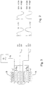
- FIG. 1 schematically shows a measurement circuit according to the invention.
- a piezoelectric transducer T is symmetrically connected to the two conductive wires a and b of a symmetrical screened transmission line L.
- the transducer T is enclosed in a screened enclosure B which can be electrically connected to the screen of the transmission line or cable L.
- the conductors a and b are respectively connected to two charge amplifiers A1 and A2 each provided with a feedback capacitor Cf.
- the outputs of the amplifiers A1 and A2 are connected to an amplifier or summing device S1 delivering an output voltage Eo.
- the transducer T which is intended to measure the vibrations of an engine, for example an airplane or a machine tool, etc.
- the circuit of FIG. 1 therefore makes it possible to measure the vibrations of the device on which the transducer.
- to assess quality defects transducer or transmission line, or even measuring device itself, such as interruptions, short circuits, poor insulation, intermittent contact as well as parasitic signals induced from outside in the circuit of measurement it is advantageous and necessary not only to process signals E1 and E2 in differential mode but also in common mode.
- an amplifier is provided.
- A3 which is also a summator S2, as indicated in figure 1.
- the fault amplifier A3 delivers a fault signal Ed, which represents the sum of the signals applied to its Entrance.
- an auxiliary generator G is provided of which the output signal Eg of suitable frequency which differs from the measurement frequency is powered by a wire conductor D 'of cable L to transducer T where the signal is transmitted by injection capacities Ct1 and Ct2 likewise value at terminals c and d of the transducer.
- Ct1 and Ct2 capacities are integrated in the T sensor according to Fig. 3.
- the generator G supplies two electrodes g, each between an outer insulating layer i and a layer in piezoelectric material p of the transducer. As shown in FIG.
- an auxiliary AC signal likewise phase Qt1, Qt2 is thus transmitted on terminals c and d of the transducer.
- the Eg1 signal at the amplifier output load A1 corresponds to the signal Qt1.
- the signal Eg2 at the charge amplifier A2 output corresponds to signal Qt2.
- Equation 2 is valid if the monitored machine is in works while equation 2 ') is valid if the machine monitored is stopped.
- Eo output signals and Ed are given by the relations 2), respectively 2 '), and the signal Eo is proportional to the intensity of the engine vibrations.
- the Eo and Ed signals are 0. If the short circuit exists between one of the terminals c or d and box B or between a point on line a or the line b and the cable shield C ', one of the input signals of the evaluation device is 0 and the measurement signals Eo and default Ed are equal and in principle equal to half of the value of the signal Eo in the normal case.
- the amplitude of the Eo and Ed signals depends on where the cut, and this by the fact that the current must close by the coupling capacity between the shield (enclosure) of the cable transducer and shielding.
- knowledge of the Eo and Ed signals can provide, at least in theory, information about the location of the cutoff, between the transducer and the detection.
- the amplitude of the Eo signal will be intermediate between 0 and 2Q / Cf.
- the amplitudes Eo and Ed signals are a function of the duration of the interruption of the link and its recurrence.
- spurious signal detection noise
- the first of these influences is produced by what we calls a ground loop in case the earth of the machine is connected to the earth of the electronics.
- a current flowing in this loop produced by through stray capacitances Cp, which can be different from each other, a spurious signal in each of conductors of the transmission line.
- Cp stray capacitances
- Another influence is that produced by coupling electromagnetic noise.
- a high intensity alternating current flows in a conductor next to the transmission line L and parallel to it.
- this current can induce in each of the conductors of this a parasitic voltage E1n and E2n, these voltages are in phase but can be of different intensities.
- the difference absolute values of the resulting influence of these voltages appear at the output Eo and their sum at the output Ed. In relation to their frequencies, they can therefore be detected.
- the measurement circuit according to the invention allows, by the evaluation of the Eo and Ed signals, to detect faults such as short circuits, interruptions, etc., both in the transducer and in the line of transmission, or even in the measuring device itself, as well as the detection of parasitic influences coming from outside.
- the diagram of the measuring device including the elements A1, A2, S1 and A3 (S2) is particularly simple.
- the charge amplifiers A1 and A2 have been shown as being part of the measurement device according to the invention. However, this is not an obligation and these amplifiers can without other being mounted in the shielding enclosure B thereof. In this case, it is no longer the Q + and Q- loads of the transducer which constitute the input signals of the measuring device, but rather the voltages
- the generator G can be integrated into the enclosure B of the transducer.
- capacitors Ct1, Ct2 can be provided as shown in Fig. 1.
- the solution according to FIG. 3 presents the advantage that the presence or absence of the transducer T is indicated by the presence, respectively the absence, of the auxiliary signal on lines a and b.
- This signal could also be generated by electromechanical excitation of the transducer powered by the Eg output signal from the auxiliary generator G.
- the signals auxiliaries on the conducting wires a and b are in phase opposite which brings up opposite information Ed for certain conditions, in particular the normal state of circuit.
- any other suitable transducer eg. ex. a transducer inductive, capacitive, resistive or electro-optical can be used with the electronic circuit described above or a analog circuit adapted to the specific characteristic of the transducer.
- the auxiliary signal could be a continuous signal (DC).
Abstract
Description
La présente invention concerne un circuit de mesure selon le
préambule de la revendication 1.The present invention relates to a measurement circuit according to the
preamble of
Un tel circuit est connu du brevet suisse no. 658 908. Ce circuit a pour but par exemple de détecter les vibrations d'une machine tournante qui peut être un moteur d'avion ou toute autre structure vibrante. Il permet d'évaluer la qualité du circuit, c'est-à-dire de déceler des défauts tels qu'interruptions, court-circuits, mauvaise isolation, liaison intermittente aussi bien au niveau du capteur qu'à celui de la transmission. En plus, il est aussi possible de détecter des influences parasites extérieures qui sont produites par un couplage électromagnétique, un couplage électrostatique ou par une boucle de terre. De manière générale, une ligne de transmission entre le transducteur et le circuit de mesure peut être interrompue par un ou plusieurs connecteurs au passage de parois ou de cloisons disposées entre le transducteur piézo-électrique et le dispositif de mesure des vibrations ou pressions.Such a circuit is known from Swiss patent no. 658 908. This circuit aims for example to detect vibrations a rotating machine which may be an aircraft engine or any other vibrating structure. It assesses the quality of the circuit, i.e. to detect faults such as only interruptions, short circuits, poor insulation, intermittent link both at the sensor and at the sensor that of transmission. In addition, it is also possible to detect external parasitic influences which are produced by electromagnetic coupling, coupling electrostatic or by a ground loop. So general, a transmission line between the transducer and the measuring circuit can be interrupted by one or several connectors for the passage of walls or partitions arranged between the piezoelectric transducer and the vibration or pressure measuring device.
Malgré les possibilités avantageuses susmentionnées le circuit connu souffre de certains désavantages. Les signaux de test respectivement les signaux de défaut dépendent de la marche du dispositif, par exemple du moteur surveillé qui produit par sa vibration le signal de test et de mesure dans le transducteur. Cette nécessité est particulièrement gênante par exemple pour la surveillance d'un moteur d' avion ou d'une grande machine comme une turbine à gaz ou à vapeur où une mise en marche est nécessaire pour obtenir un résultat de test.Despite the advantageous possibilities mentioned above the known circuit suffers from certain disadvantages. The signals respectively the fault signals depend on the operation of the device, for example of the monitored motor which produced by its vibration the test and measurement signal in the transducer. This necessity is particularly troublesome for example for monitoring an aircraft engine or a large machine such as a gas or steam turbine where start-up is required to obtain a test result.
Le but de la présente invention est de permettre une surveillance complète non seulement pendant la marche mais aussi lors de l'arrêt de l'objet à mesurer et à tester. Ce but est atteint par les mesures selon la revendication 1. Par l'injection d'un signal auxiliaire "artificiel" on simule un bruit en mode commun connu qu'on utilise pour tester la chaíne de mesure. En plus, il en résulte les avantages suivants:
- Le signal de test auxiliaire est indépendant de l'amplitude et de la fréquence de vibration,
- les paramètres tels que fréquence ou amplitude sont prévisibles,
- la présence du transducteur peut être détectée.
- The auxiliary test signal is independent of the amplitude and frequency of vibration,
- parameters such as frequency or amplitude are predictable,
- the presence of the transducer can be detected.
L'invention va être décrite ci-après à titre d'exemple et à l'aide des dessins en annexe dans lesquels:
- La figure 1
- est une vue schématique d'un circuit de mesure avec transducteur piézo-électrique,
- la figure 2
- montre les signaux aux bornes du transducteur respectivement aux entrées des amplificateurs S1 et S2, et
- la figure 3
- illustre les détails d'un transducteur selon l' invention.
- Figure 1
- is a schematic view of a measurement circuit with piezoelectric transducer,
- figure 2
- shows the signals at the transducer terminals respectively at the inputs of amplifiers S1 and S2, and
- figure 3
- illustrates the details of a transducer according to the invention.
La figure 1 montre schématiquement un circuit de mesure
selon l'invention. Un transducteur piézo-électrique T est
relié de manière symétrique aux deux fils conducteurs a et b
d'une ligne de transmission symétrique blindée L. Le
transducteur T est enfermé dans une enceinte blindée B qui
peut être reliée électriquement au blindage de la ligne de
transmission ou câble L. A leur sortie du câble, les
conducteurs a et b sont reliés respectivement à deux
amplificateurs de charge A1 et A2 pourvus chacun d'un
condensateur de contre-réaction Cf. Les sorties des
amplificateurs A1 et A2 sont reliées à un amplificateur de
mesure ou sommateur S1 délivrant une tension de sortie Eo.
Le transducteur T qui est destiné à mesurer les vibrations
d'un moteur, par exemple d'avion ou de machine-outil, etc.
(non représenté) sur lequel il est monté, a une sensibilité
exprimée en pC/g (picocoulomb/g). Pour une accélération g
donnée, il délivre des charges Q+ et Q- en principe de même
valeur mais de polarité opposée à l'entrée des
amplificateurs de charge A1 et A2 qui délivrent à leur
sortie des tensions E1 et E2 proportionnelles aux charges
mais en opposition de phase (Fig. 2). Ces tensions sont
données par les relations:
En admettant par exemple une sensibilité du transducteur de
50 pC/g, une accélération de pointe de 1g et Cf de valeur 1
nF, les charges Q+ et Q- ont chacune une valeur de pointe de
50 pC et la relation ci-dessus montre que Eo = 0,1V de
pointe.By admitting for example a sensitivity of the transducer
50 pC / g, a peak acceleration of 1g and Cf of
Le circuit de la figure 1 permet donc de mesurer les vibrations du dispositif sur lequel est monté le transducteur. Toutefois, pour évaluer des défauts de qualité du transducteur ou de la ligne de transmission, ou même du dispositif de mesure lui-même, tels qu'interruptions, court-circuits, mauvaise isolation, contact intermittent ainsi que des signaux parasites induits de l'extérieur dans le circuit de mesure, il est avantageux et nécessaire non seulement de traiter les signaux E1 et E2 en mode différentiel mais aussi en mode commun. Dans ce but, on prévoit un amplificateur de défaut A3 qui est aussi un sommateur S2, comme indiqué en figure 1.The circuit of FIG. 1 therefore makes it possible to measure the vibrations of the device on which the transducer. However, to assess quality defects transducer or transmission line, or even measuring device itself, such as interruptions, short circuits, poor insulation, intermittent contact as well as parasitic signals induced from outside in the circuit of measurement it is advantageous and necessary not only to process signals E1 and E2 in differential mode but also in common mode. For this purpose, an amplifier is provided. default A3 which is also a summator S2, as indicated in figure 1.
L'amplificateur de défaut A3 délivre un signal de défaut Ed, lequel représente la somme des signaux appliqués a son entrée.The fault amplifier A3 delivers a fault signal Ed, which represents the sum of the signals applied to its Entrance.
Dans le circuit représenté à la figure 1, on a tenu compte du fait que des signaux parasites E1n et E2n peuvent être superposés aux signaux utiles E1 et E2. Comme montré par la figure 3, les charges Q1n et Q2n correspondantes aux signaux parasites E1n et E2n sont aussi présentes sur les fils conducteurs a et b respectivement.In the circuit represented in figure 1, one took account the fact that spurious signals E1n and E2n can be superimposed on the useful signals E1 and E2. As shown by the Figure 3, the charges Q1n and Q2n corresponding to the signals E1n and E2n parasites are also present on the wires conductors a and b respectively.
Comme indiqué en figure 2, laquelle illustre également les signaux E1 et E2, les signaux parasites E1n et E2n sont induits avec la même phase sur chacun des fils conducteurs a et b de la ligne de transmission L. Les flèches utilisées dans la représentation de signaux à la figure 2 p. ex. entre Q+ et E1 signifient "cause" ou "donne lieu à".As shown in Figure 2, which also illustrates the signals E1 and E2, the spurious signals E1n and E2n are induced with the same phase on each of the conductive wires a and b of the transmission line L. The arrows used in the representation of signals in Figure 2 p. ex. Between Q + and E1 mean "cause" or "gives rise to".
Pour effectuer un test pendant la marche ou l'arrêt de la machine surveillée par le transducteur, respectivement le circuit de mesure, on prévoit un générateur auxiliaire G dont le signal de sortie Eg de fréquence convenable qui diffère de la fréquence de mesure est alimenté par un fil conducteur D' du câble L au transducteur T où le signal est transmis par des capacités d'injection Ct1 et Ct2 de même valeur aux bornes c et d du transducteur. De préférence, les capacités Ct1 et Ct2 sont intégrées dans le capteur T selon la Fig. 3. Le générateur G alimente deux électrodes g, chacune entre une couche isolante extérieure i et une couche en matière piézo-électrique p du transducteur. Comme montré par la figure 3, un signal alternatif auxiliaire de même phase Qt1, Qt2 est ainsi transmis sur les bornes c et d du transducteur. Le signal Eg1 à la sortie de l'amplificateur de charge A1 correspond au signal Qt1.Le signal Eg2 à la sortie de l'amplificateur de charge A2 correspond au signal Qt2.To perform a test while the on or off of the machine monitored by the transducer, respectively the measuring circuit, an auxiliary generator G is provided of which the output signal Eg of suitable frequency which differs from the measurement frequency is powered by a wire conductor D 'of cable L to transducer T where the signal is transmitted by injection capacities Ct1 and Ct2 likewise value at terminals c and d of the transducer. Preferably, Ct1 and Ct2 capacities are integrated in the T sensor according to Fig. 3. The generator G supplies two electrodes g, each between an outer insulating layer i and a layer in piezoelectric material p of the transducer. As shown in FIG. 3, an auxiliary AC signal likewise phase Qt1, Qt2 is thus transmitted on terminals c and d of the transducer. The Eg1 signal at the amplifier output load A1 corresponds to the signal Qt1. The signal Eg2 at the charge amplifier A2 output corresponds to signal Qt2.
Dans le cas général, les signaux de sortie Eo et Ed sont
donnés par les relations suivantes:
L'équation 2) est valable si la machine surveillée est en marche tandis que l'équation 2') est valable si la machine surveillée est en arrêt.Equation 2) is valid if the monitored machine is in works while equation 2 ') is valid if the machine monitored is stopped.
Les relations 1), 2) et 2') ci-dessus permettent d'évaluer la qualité du circuit de mesure.The relations 1), 2) and 2 ') above make it possible to evaluate the quality of the measurement circuit.
Dans le cas normal, c'est-à-dire si tous les éléments du circuit fonctionnent correctement, les signaux de sortie Eo et Ed sont donnés par les relations 2), respectivement 2'), et le signal Eo est proportionnel à l'intensité des vibrations du moteur.In the normal case, i.e. if all the elements of the circuit working properly, Eo output signals and Ed are given by the relations 2), respectively 2 '), and the signal Eo is proportional to the intensity of the engine vibrations.
En cas d'un court-circuit, soit dans le transducteur, soit le long de la ligne de transmission les signaux Eo et Ed sont 0. Si le court-circuit existe entre une des bornes c ou d et le boítier B ou entre un point de la ligne a ou la ligne b et le blindage C' du câble, un des signaux d'entrée du dispositif d'évaluation est 0 et les signaux de mesure Eo et de défaut Ed sont égaux et en principe égaux à la moitié de la valeur du signal Eo dans le cas normal.In the event of a short circuit, either in the transducer or along the transmission line the Eo and Ed signals are 0. If the short circuit exists between one of the terminals c or d and box B or between a point on line a or the line b and the cable shield C ', one of the input signals of the evaluation device is 0 and the measurement signals Eo and default Ed are equal and in principle equal to half of the value of the signal Eo in the normal case.
Dans le cas d'une interruption dans le transducteur ou dans la ligne à proximité du transducteur, l'amplitude des signaux Eo et Ed dépend de l'endroit où se trouve la coupure, et ceci par le fait que le courant doit se refermer par la capacité de couplage entre le blindage (enceinte) du transducteur et le blindage du câble L. Ce qui précède montre que la connaissance des signaux Eo et Ed peut fournir, au moins en théorie, des informations sur l'endroit de la coupure, entre le transducteur et le dispositif de détection.In the event of an interruption in the transducer or in the line near the transducer, the amplitude of the Eo and Ed signals depends on where the cut, and this by the fact that the current must close by the coupling capacity between the shield (enclosure) of the cable transducer and shielding. The above shows that knowledge of the Eo and Ed signals can provide, at least in theory, information about the location of the cutoff, between the transducer and the detection.
Dans le cas de mauvaise isolation du transducteur ou de la ligne, l'amplitude du signal Eo sera intermédiaire entre 0 et 2Q/Cf. En cas de liaison intermittente, les amplitudes des signaux Eo et Ed sont fonction de la durée de l'interruption de la liaison et de sa récurrence.In the event of poor insulation of the transducer or line, the amplitude of the Eo signal will be intermediate between 0 and 2Q / Cf. In case of intermittent link, the amplitudes Eo and Ed signals are a function of the duration of the interruption of the link and its recurrence.
Examinons maintenant la détection de signaux parasites (noise) induits de l'extérieur dans le circuit de mesure. La première de ces influences est produite par ce que l'on appelle une boucle de masse (ground loop) dans le cas où la masse de la machine est reliée à la masse de l'électronique. Un courant circulant dans cette boucle produit par l'intermédiaire des capacités parasites Cp, qui peuvent être différentes entre elles, un signal parasite dans chacun des fils conducteurs de la ligne de transmission. Ces signaux sont en phase et leur somme apparaít à la sortie Ed, tandis que leur différence affecte la sortie Eo. Cet effet parasite peut donc être détecté.Now let's look at spurious signal detection (noise) induced from outside in the measurement circuit. The first of these influences is produced by what we calls a ground loop in case the earth of the machine is connected to the earth of the electronics. A current flowing in this loop produced by through stray capacitances Cp, which can be different from each other, a spurious signal in each of conductors of the transmission line. These signals are in phase and their sum appears at the output Ed, while that their difference affects the Eo output. This parasitic effect can therefore be detected.
Une autre influence est celle produite par couplage électromagnétique (electromagnetic noise) . Dans ce cas, un courant alternatif de forte intensité circule dans un conducteur voisin de la ligne de transmission L et parallèlement à celle-ci. Malgré le blindage de la ligne, ce courant peut induire dans chacun des fils conducteurs de celle-ci une tension parasite E1n et E2n, ces tensions sont en phase mais peuvent être d'intensités différentes. Selon les relations 1) et 2) mentionnées plus haut, la différence de valeurs absolues de l'influence résultante de ces tensions apparaít à la sortie Eo et leur somme à la sortie Ed. En relation avec leurs fréquences, elles peuvent donc être détectées.Another influence is that produced by coupling electromagnetic noise. In this case, a high intensity alternating current flows in a conductor next to the transmission line L and parallel to it. Despite the line's armor, this current can induce in each of the conductors of this a parasitic voltage E1n and E2n, these voltages are in phase but can be of different intensities. According to the relationships 1) and 2) mentioned above, the difference absolute values of the resulting influence of these voltages appear at the output Eo and their sum at the output Ed. In relation to their frequencies, they can therefore be detected.
Enfin, il existe encore une influence capacitive (electrostatic noise) produite par exemple par les capacités entre des contacts d'un connecteur voisins de ceux qui dans ce connecteur correspondent aux conducteurs a et b de la ligne de transmission, lors de la traversée d'une cloison. A travers les capacités parasites, des tensions induites parasites peuvent exister à l'entrée du dispositif de mesure. Comme précédemment, ces tensions peuvent être détectées par les tensions Eo et Ed mesurées à la fréquence des tensions perturbatrices.Finally, there is still a capacitive influence (electrostatic noise) produced for example by capacities between connector contacts close to those in this connector correspond to conductors a and b of the transmission line, when crossing a partition. AT through stray capacitances, induced voltages parasites may exist at the input of the measured. As before, these tensions can be detected by the voltages Eo and Ed measured at the frequency disruptive tensions.
De manière générale, le circuit de mesure selon l'invention permet, par l'évaluation des signaux Eo et Ed, de détecter des défauts tels que court-circuits, interruptions, etc., aussi bien dans le transducteur que dans la ligne de transmission, ou même dans le dispositif de mesure lui-même, ainsi que la détection des influences parasites venant de l'extérieur. In general, the measurement circuit according to the invention allows, by the evaluation of the Eo and Ed signals, to detect faults such as short circuits, interruptions, etc., both in the transducer and in the line of transmission, or even in the measuring device itself, as well as the detection of parasitic influences coming from outside.
Le schéma du dispositif de mesure comprenant les éléments A1, A2, S1 et A3 (S2) est particulièrement simple. Pour la mise en oeuvre pratique du circuit de mesure, on peut prévoir que les signaux de mesure Eo et de défaut Ed, éventuellement après filtrage des composants de fréquences indésirables, et après redressement et digitalisation, sont utilisés dans un algorithme adéquat permettant de délivrer des indications sur la qualité du circuit de mesure.The diagram of the measuring device including the elements A1, A2, S1 and A3 (S2) is particularly simple. For the practical implementation of the measurement circuit, you can provide that the measurement signals Eo and fault Ed, possibly after filtering the frequency components undesirable, and after recovery and digitization, are used in an adequate algorithm to deliver indications on the quality of the measurement circuit.
Dans les figures décrites ci-dessus, les amplificateurs de
charge A1 et A2 ont été représentés comme faisant partie du
dispositif de mesure selon l'invention. Ceci n'est toutefois
pas une obligation et ces amplificateurs peuvent sans autre
être montés dans l'enceinte B de blindage de celui-ci. Dans
ce cas, ce ne sont plus les charges Q+ et Q- du transducteur
qui constituent les signaux d'entrée du dispositif de mesure
mais bien les tensions
Au lieu des capacités intégrées au transducteur selon Fig. 3, des condensateurs Ct1, Ct2 peuvent être prévus comme indiqué en Fig. 1. La solution selon la Fig. 3 présente l'avantage que la présence ou l'absence du transducteur T est indiqué par la présence, respectivement l'absence, du signal auxiliaire sur les lignes a et b. Ce signal pourrait aussi être généré par excitation électromécanique du transducteur alimenté par le signal de sortie Eg du générateur auxiliaire G. Dans ce cas, les signaux auxiliaires sur les fils conducteurs a et b sont en phase opposée ce qui amène à des informations opposées Ed pour certaines conditions, en particulier l'état normal du circuit. Instead of the capacitors integrated in the transducer according to FIG. 3, capacitors Ct1, Ct2 can be provided as shown in Fig. 1. The solution according to FIG. 3 presents the advantage that the presence or absence of the transducer T is indicated by the presence, respectively the absence, of the auxiliary signal on lines a and b. This signal could also be generated by electromechanical excitation of the transducer powered by the Eg output signal from the auxiliary generator G. In this case, the signals auxiliaries on the conducting wires a and b are in phase opposite which brings up opposite information Ed for certain conditions, in particular the normal state of circuit.
Au lieu du transducteur piézo-électrique, n'importe quel autre transducteur convenable, p. ex. un transducteur inductif, capacitif, résistif ou électro-optique peut être utilisé avec le circuit électronique décrit ci-devant ou un circuit analogue adapté à la caractéristique spécifique du transducteur.Instead of the piezoelectric transducer, any other suitable transducer, eg. ex. a transducer inductive, capacitive, resistive or electro-optical can be used with the electronic circuit described above or a analog circuit adapted to the specific characteristic of the transducer.
Pour certaines applications, le signal auxiliaire pourrait être un signal continu (DC).For some applications, the auxiliary signal could be a continuous signal (DC).
Claims (5)
Priority Applications (6)
| Application Number | Priority Date | Filing Date | Title |
|---|---|---|---|
| ES98810920T ES2255144T3 (en) | 1998-09-15 | 1998-09-15 | MEASUREMENT CIRCUIT. |
| EP19980810920 EP0987554B1 (en) | 1998-09-15 | 1998-09-15 | Measuring circuit |
| DK98810920T DK0987554T3 (en) | 1998-09-15 | 1998-09-15 | Measuring circuit |
| DE69832980T DE69832980T2 (en) | 1998-09-15 | 1998-09-15 | Measuring circuit |
| CA 2255975 CA2255975C (en) | 1998-09-15 | 1998-12-14 | Measuring circuit |
| US09/420,280 US6498501B2 (en) | 1998-09-15 | 1999-10-18 | Measuring circuit |
Applications Claiming Priority (1)
| Application Number | Priority Date | Filing Date | Title |
|---|---|---|---|
| EP19980810920 EP0987554B1 (en) | 1998-09-15 | 1998-09-15 | Measuring circuit |
Publications (2)
| Publication Number | Publication Date |
|---|---|
| EP0987554A1 true EP0987554A1 (en) | 2000-03-22 |
| EP0987554B1 EP0987554B1 (en) | 2005-12-28 |
Family
ID=8236322
Family Applications (1)
| Application Number | Title | Priority Date | Filing Date |
|---|---|---|---|
| EP19980810920 Expired - Lifetime EP0987554B1 (en) | 1998-09-15 | 1998-09-15 | Measuring circuit |
Country Status (5)
| Country | Link |
|---|---|
| EP (1) | EP0987554B1 (en) |
| CA (1) | CA2255975C (en) |
| DE (1) | DE69832980T2 (en) |
| DK (1) | DK0987554T3 (en) |
| ES (1) | ES2255144T3 (en) |
Cited By (4)
| Publication number | Priority date | Publication date | Assignee | Title |
|---|---|---|---|---|
| WO2001040815A1 (en) * | 1999-11-27 | 2001-06-07 | Koninklijke Philips Electronics N.V. | Testing electrical circuits |
| CN106225911A (en) * | 2016-08-29 | 2016-12-14 | 广东履安实业有限公司 | A kind of pick up for machine sound diagnosis |
| WO2020016011A1 (en) | 2018-07-19 | 2020-01-23 | Kistler Holding Ag | Measuring circuit for capturing and processing signals, and measuring device for using said measuring circuit |
| FR3098587A1 (en) * | 2019-07-08 | 2021-01-15 | Safran Aircraft Engines | Method and system for detecting open circuits of accelerometers by phase noise |
Families Citing this family (4)
| Publication number | Priority date | Publication date | Assignee | Title |
|---|---|---|---|---|
| FI120803B (en) * | 2007-05-21 | 2010-03-15 | Waertsilae Finland Oy | detector device |
| ES2784778T3 (en) | 2012-08-31 | 2020-09-30 | Meggitt Sa | Force sensor and method to test its reliability |
| EP3524988B1 (en) * | 2018-02-07 | 2022-03-30 | Analog Devices International Unlimited Company | A method of and apparatus for detecting channel imbalance in a differential signal system comprising a differential amplifier |
| GB201801995D0 (en) | 2018-02-07 | 2018-03-28 | Analog Devices Global Unlimited Co | A method of and apparatus for detecting open circuit conditions at an input to a signal chain and for detecting channel imbalance in a differential signal |
Citations (4)
| Publication number | Priority date | Publication date | Assignee | Title |
|---|---|---|---|---|
| CH658908A5 (en) * | 1983-09-06 | 1986-12-15 | Vibro Meter Ag | Measurement circuit and its use |
| US5070843A (en) * | 1989-05-15 | 1991-12-10 | Mitsubishi Denki Kabushiki Kaisha | Ignition timing control apparatus of internal-combustion engine |
| GB2253487A (en) * | 1991-03-07 | 1992-09-09 | Rover Group | A method of detecting malfunction of a piezoelectric sensor |
| WO1995006259A1 (en) * | 1993-08-24 | 1995-03-02 | A/S Brüel & Kjær | An apparatus for detecting the malfunctioning of an accelerometer |
-
1998
- 1998-09-15 ES ES98810920T patent/ES2255144T3/en not_active Expired - Lifetime
- 1998-09-15 EP EP19980810920 patent/EP0987554B1/en not_active Expired - Lifetime
- 1998-09-15 DE DE69832980T patent/DE69832980T2/en not_active Expired - Lifetime
- 1998-09-15 DK DK98810920T patent/DK0987554T3/en active
- 1998-12-14 CA CA 2255975 patent/CA2255975C/en not_active Expired - Lifetime
Patent Citations (4)
| Publication number | Priority date | Publication date | Assignee | Title |
|---|---|---|---|---|
| CH658908A5 (en) * | 1983-09-06 | 1986-12-15 | Vibro Meter Ag | Measurement circuit and its use |
| US5070843A (en) * | 1989-05-15 | 1991-12-10 | Mitsubishi Denki Kabushiki Kaisha | Ignition timing control apparatus of internal-combustion engine |
| GB2253487A (en) * | 1991-03-07 | 1992-09-09 | Rover Group | A method of detecting malfunction of a piezoelectric sensor |
| WO1995006259A1 (en) * | 1993-08-24 | 1995-03-02 | A/S Brüel & Kjær | An apparatus for detecting the malfunctioning of an accelerometer |
Cited By (5)
| Publication number | Priority date | Publication date | Assignee | Title |
|---|---|---|---|---|
| WO2001040815A1 (en) * | 1999-11-27 | 2001-06-07 | Koninklijke Philips Electronics N.V. | Testing electrical circuits |
| US6469520B1 (en) | 1999-11-27 | 2002-10-22 | Koninglijke Philips Electronics N.V. | Testing electrical circuits |
| CN106225911A (en) * | 2016-08-29 | 2016-12-14 | 广东履安实业有限公司 | A kind of pick up for machine sound diagnosis |
| WO2020016011A1 (en) | 2018-07-19 | 2020-01-23 | Kistler Holding Ag | Measuring circuit for capturing and processing signals, and measuring device for using said measuring circuit |
| FR3098587A1 (en) * | 2019-07-08 | 2021-01-15 | Safran Aircraft Engines | Method and system for detecting open circuits of accelerometers by phase noise |
Also Published As
| Publication number | Publication date |
|---|---|
| CA2255975A1 (en) | 2000-03-15 |
| DE69832980T2 (en) | 2006-07-06 |
| CA2255975C (en) | 2004-02-10 |
| DK0987554T3 (en) | 2006-03-06 |
| EP0987554B1 (en) | 2005-12-28 |
| DE69832980D1 (en) | 2006-02-02 |
| ES2255144T3 (en) | 2006-06-16 |
Similar Documents
| Publication | Publication Date | Title |
|---|---|---|
| EP0297933B1 (en) | Apparatus to check and to measure the insulation of an electric network | |
| US7936175B2 (en) | Full function test for in situ test of sensors and amplifiers | |
| EP0987554B1 (en) | Measuring circuit | |
| WO2000019221A1 (en) | Method and device for locating an insulation fault in an electric cable | |
| FR2649155A1 (en) | DYNAMOMETRIC MEASURING DEVICE FOR DRILL ROD | |
| EP0346211B1 (en) | Touch switch using the properties of a liquid crystal | |
| EP0493271B1 (en) | Measuring bridge for reference voltage for a device for monitoring and measuring the insulation of a DC electric network | |
| FR2584822A1 (en) | DEVICE FOR MEASURING THE RATIO OF TWO CAPACITIES OF LOW VALUES | |
| FR2480441A1 (en) | METHOD AND DEVICES FOR IDENTIFYING DEFECTIVE PHASES IN AN ELECTRICAL DISTRIBUTION NETWORK | |
| FR2610110A1 (en) | STRUCTURAL DEFECT DETECTION DEVICE | |
| CA2881524C (en) | Analogue amplification device intended in particular for a laser anemometer | |
| US6498501B2 (en) | Measuring circuit | |
| EP0043747B1 (en) | Acoustic remote control device testable by means of supply voltage variation | |
| EP0492394B1 (en) | Apparatus for the non-destructive testing of Eddy-Currents with commutation for flux-addition -flux- subtraction | |
| CH658908A5 (en) | Measurement circuit and its use | |
| EP1250607B1 (en) | Method and device for monitoring a telecommunication cable | |
| EP0358145B1 (en) | Screened tension-measuring appliance for a triphase installation | |
| FR2664972A1 (en) | Displacement sensor with oscillating (resonant) circuit magnetically coupled to a conducting target | |
| FR2581196A1 (en) | Method and device for measuring resistivity, particularly for dielectric liquids of very high resistivity | |
| EP0965819B1 (en) | Electronic interface circuit for a piezo-electric sensor | |
| WO1997018438A1 (en) | Method and device for measuring axial deviation in a tautwire alignment system | |
| FR2688891A1 (en) | DEVICE FOR TESTING A RECEIVER GROUP. | |
| EP0511137A1 (en) | Procedure and apparatus for measuring and monitoring the electrical isolation of an active system | |
| EP0477087A1 (en) | Device for processing a signal originating from a sensor having a differentiating response | |
| FR2507782A1 (en) | Tachometer for DC motor in vehicle air conditioner - has current transformer and wave shaping circuit for transients caused by commutations induced in transformer secondary |
Legal Events
| Date | Code | Title | Description |
|---|---|---|---|
| PUAI | Public reference made under article 153(3) epc to a published international application that has entered the european phase |
Free format text: ORIGINAL CODE: 0009012 |
|
| AK | Designated contracting states |
Kind code of ref document: A1 Designated state(s): BE CH DE DK ES FR GB IT LI NL |
|
| AX | Request for extension of the european patent |
Free format text: AL;LT;LV;MK;RO;SI |
|
| 17P | Request for examination filed |
Effective date: 20000620 |
|
| AKX | Designation fees paid |
Free format text: BE CH DE DK ES FR GB IT LI NL |
|
| 17Q | First examination report despatched |
Effective date: 20040601 |
|
| GRAP | Despatch of communication of intention to grant a patent |
Free format text: ORIGINAL CODE: EPIDOSNIGR1 |
|
| GRAS | Grant fee paid |
Free format text: ORIGINAL CODE: EPIDOSNIGR3 |
|
| GRAA | (expected) grant |
Free format text: ORIGINAL CODE: 0009210 |
|
| AK | Designated contracting states |
Kind code of ref document: B1 Designated state(s): BE CH DE DK ES FR GB IT LI NL |
|
| REG | Reference to a national code |
Ref country code: GB Ref legal event code: FG4D Free format text: NOT ENGLISH |
|
| REG | Reference to a national code |
Ref country code: CH Ref legal event code: NV Representative=s name: AMMANN PATENTANWAELTE AG BERN Ref country code: CH Ref legal event code: EP |
|
| GBT | Gb: translation of ep patent filed (gb section 77(6)(a)/1977) |
Effective date: 20051229 |
|
| REF | Corresponds to: |
Ref document number: 69832980 Country of ref document: DE Date of ref document: 20060202 Kind code of ref document: P |
|
| REG | Reference to a national code |
Ref country code: DK Ref legal event code: T3 |
|
| REG | Reference to a national code |
Ref country code: ES Ref legal event code: FG2A Ref document number: 2255144 Country of ref document: ES Kind code of ref document: T3 |
|
| PG25 | Lapsed in a contracting state [announced via postgrant information from national office to epo] |
Ref country code: BE Free format text: LAPSE BECAUSE OF NON-PAYMENT OF DUE FEES Effective date: 20060930 |
|
| PLBE | No opposition filed within time limit |
Free format text: ORIGINAL CODE: 0009261 |
|
| STAA | Information on the status of an ep patent application or granted ep patent |
Free format text: STATUS: NO OPPOSITION FILED WITHIN TIME LIMIT |
|
| 26N | No opposition filed |
Effective date: 20060929 |
|
| PG25 | Lapsed in a contracting state [announced via postgrant information from national office to epo] |
Ref country code: NL Free format text: LAPSE BECAUSE OF NON-PAYMENT OF DUE FEES Effective date: 20070401 |
|
| NLV4 | Nl: lapsed or anulled due to non-payment of the annual fee |
Effective date: 20070401 |
|
| PGFP | Annual fee paid to national office [announced via postgrant information from national office to epo] |
Ref country code: DK Payment date: 20070914 Year of fee payment: 10 |
|
| REG | Reference to a national code |
Ref country code: ES Ref legal event code: FD2A Effective date: 20060916 |
|
| BERE | Be: lapsed |
Owner name: S.A. *VIBRO-METER Effective date: 20060930 |
|
| PG25 | Lapsed in a contracting state [announced via postgrant information from national office to epo] |
Ref country code: ES Free format text: LAPSE BECAUSE OF NON-PAYMENT OF DUE FEES Effective date: 20060916 |
|
| PGFP | Annual fee paid to national office [announced via postgrant information from national office to epo] |
Ref country code: IT Payment date: 20070925 Year of fee payment: 10 |
|
| REG | Reference to a national code |
Ref country code: DK Ref legal event code: EBP |
|
| PG25 | Lapsed in a contracting state [announced via postgrant information from national office to epo] |
Ref country code: IT Free format text: LAPSE BECAUSE OF NON-PAYMENT OF DUE FEES Effective date: 20080915 |
|
| PG25 | Lapsed in a contracting state [announced via postgrant information from national office to epo] |
Ref country code: DK Free format text: LAPSE BECAUSE OF NON-PAYMENT OF DUE FEES Effective date: 20090331 |
|
| REG | Reference to a national code |
Ref country code: DE Ref legal event code: R082 Ref document number: 69832980 Country of ref document: DE Representative=s name: MAI DOERR BESIER EUROPEAN PATENT ATTORNEYS - E, DE Ref country code: DE Ref legal event code: R082 Ref document number: 69832980 Country of ref document: DE Representative=s name: MAI DOERR BESIER PATENTANWAELTE, DE |
|
| REG | Reference to a national code |
Ref country code: FR Ref legal event code: PLFP Year of fee payment: 19 |
|
| REG | Reference to a national code |
Ref country code: FR Ref legal event code: PLFP Year of fee payment: 20 |
|
| PGFP | Annual fee paid to national office [announced via postgrant information from national office to epo] |
Ref country code: CH Payment date: 20170912 Year of fee payment: 20 Ref country code: FR Payment date: 20170829 Year of fee payment: 20 Ref country code: DE Payment date: 20170912 Year of fee payment: 20 Ref country code: GB Payment date: 20170913 Year of fee payment: 20 |
|
| REG | Reference to a national code |
Ref country code: CH Ref legal event code: PL |
|
| REG | Reference to a national code |
Ref country code: DE Ref legal event code: R071 Ref document number: 69832980 Country of ref document: DE |
|
| REG | Reference to a national code |
Ref country code: GB Ref legal event code: PE20 Expiry date: 20180914 |
|
| PG25 | Lapsed in a contracting state [announced via postgrant information from national office to epo] |
Ref country code: GB Free format text: LAPSE BECAUSE OF EXPIRATION OF PROTECTION Effective date: 20180914 |