EP0989384A2 - Miniaturized position sensor - Google Patents
Miniaturized position sensor Download PDFInfo
- Publication number
- EP0989384A2 EP0989384A2 EP99307530A EP99307530A EP0989384A2 EP 0989384 A2 EP0989384 A2 EP 0989384A2 EP 99307530 A EP99307530 A EP 99307530A EP 99307530 A EP99307530 A EP 99307530A EP 0989384 A2 EP0989384 A2 EP 0989384A2
- Authority
- EP
- European Patent Office
- Prior art keywords
- coils
- assembly
- coil
- photolithographic
- axes
- Prior art date
- Legal status (The legal status is an assumption and is not a legal conclusion. Google has not performed a legal analysis and makes no representation as to the accuracy of the status listed.)
- Granted
Links
Images


Classifications
-
- A—HUMAN NECESSITIES
- A61—MEDICAL OR VETERINARY SCIENCE; HYGIENE
- A61B—DIAGNOSIS; SURGERY; IDENTIFICATION
- A61B5/00—Measuring for diagnostic purposes; Identification of persons
- A61B5/06—Devices, other than using radiation, for detecting or locating foreign bodies ; determining position of probes within or on the body of the patient
- A61B5/065—Determining position of the probe employing exclusively positioning means located on or in the probe, e.g. using position sensors arranged on the probe
-
- A—HUMAN NECESSITIES
- A61—MEDICAL OR VETERINARY SCIENCE; HYGIENE
- A61B—DIAGNOSIS; SURGERY; IDENTIFICATION
- A61B5/00—Measuring for diagnostic purposes; Identification of persons
- A61B5/06—Devices, other than using radiation, for detecting or locating foreign bodies ; determining position of probes within or on the body of the patient
- A61B5/061—Determining position of a probe within the body employing means separate from the probe, e.g. sensing internal probe position employing impedance electrodes on the surface of the body
- A61B5/062—Determining position of a probe within the body employing means separate from the probe, e.g. sensing internal probe position employing impedance electrodes on the surface of the body using magnetic field
-
- A—HUMAN NECESSITIES
- A61—MEDICAL OR VETERINARY SCIENCE; HYGIENE
- A61B—DIAGNOSIS; SURGERY; IDENTIFICATION
- A61B5/00—Measuring for diagnostic purposes; Identification of persons
- A61B5/68—Arrangements of detecting, measuring or recording means, e.g. sensors, in relation to patient
- A61B5/6846—Arrangements of detecting, measuring or recording means, e.g. sensors, in relation to patient specially adapted to be brought in contact with an internal body part, i.e. invasive
- A61B5/6847—Arrangements of detecting, measuring or recording means, e.g. sensors, in relation to patient specially adapted to be brought in contact with an internal body part, i.e. invasive mounted on an invasive device
- A61B5/6852—Catheters
-
- G—PHYSICS
- G01—MEASURING; TESTING
- G01B—MEASURING LENGTH, THICKNESS OR SIMILAR LINEAR DIMENSIONS; MEASURING ANGLES; MEASURING AREAS; MEASURING IRREGULARITIES OF SURFACES OR CONTOURS
- G01B7/00—Measuring arrangements characterised by the use of electric or magnetic techniques
- G01B7/003—Measuring arrangements characterised by the use of electric or magnetic techniques for measuring position, not involving coordinate determination
-
- G—PHYSICS
- G01—MEASURING; TESTING
- G01B—MEASURING LENGTH, THICKNESS OR SIMILAR LINEAR DIMENSIONS; MEASURING ANGLES; MEASURING AREAS; MEASURING IRREGULARITIES OF SURFACES OR CONTOURS
- G01B7/00—Measuring arrangements characterised by the use of electric or magnetic techniques
- G01B7/004—Measuring arrangements characterised by the use of electric or magnetic techniques for measuring coordinates of points
-
- G—PHYSICS
- G01—MEASURING; TESTING
- G01B—MEASURING LENGTH, THICKNESS OR SIMILAR LINEAR DIMENSIONS; MEASURING ANGLES; MEASURING AREAS; MEASURING IRREGULARITIES OF SURFACES OR CONTOURS
- G01B7/00—Measuring arrangements characterised by the use of electric or magnetic techniques
- G01B7/30—Measuring arrangements characterised by the use of electric or magnetic techniques for measuring angles or tapers; for testing the alignment of axes
-
- G—PHYSICS
- G01—MEASURING; TESTING
- G01D—MEASURING NOT SPECIALLY ADAPTED FOR A SPECIFIC VARIABLE; ARRANGEMENTS FOR MEASURING TWO OR MORE VARIABLES NOT COVERED IN A SINGLE OTHER SUBCLASS; TARIFF METERING APPARATUS; MEASURING OR TESTING NOT OTHERWISE PROVIDED FOR
- G01D5/00—Mechanical means for transferring the output of a sensing member; Means for converting the output of a sensing member to another variable where the form or nature of the sensing member does not constrain the means for converting; Transducers not specially adapted for a specific variable
- G01D5/12—Mechanical means for transferring the output of a sensing member; Means for converting the output of a sensing member to another variable where the form or nature of the sensing member does not constrain the means for converting; Transducers not specially adapted for a specific variable using electric or magnetic means
- G01D5/14—Mechanical means for transferring the output of a sensing member; Means for converting the output of a sensing member to another variable where the form or nature of the sensing member does not constrain the means for converting; Transducers not specially adapted for a specific variable using electric or magnetic means influencing the magnitude of a current or voltage
- G01D5/20—Mechanical means for transferring the output of a sensing member; Means for converting the output of a sensing member to another variable where the form or nature of the sensing member does not constrain the means for converting; Transducers not specially adapted for a specific variable using electric or magnetic means influencing the magnitude of a current or voltage by varying inductance, e.g. by a movable armature
- G01D5/204—Mechanical means for transferring the output of a sensing member; Means for converting the output of a sensing member to another variable where the form or nature of the sensing member does not constrain the means for converting; Transducers not specially adapted for a specific variable using electric or magnetic means influencing the magnitude of a current or voltage by varying inductance, e.g. by a movable armature by influencing the mutual induction between two or more coils
- G01D5/2073—Mechanical means for transferring the output of a sensing member; Means for converting the output of a sensing member to another variable where the form or nature of the sensing member does not constrain the means for converting; Transducers not specially adapted for a specific variable using electric or magnetic means influencing the magnitude of a current or voltage by varying inductance, e.g. by a movable armature by influencing the mutual induction between two or more coils by movement of a single coil with respect to two or more coils
-
- G—PHYSICS
- G01—MEASURING; TESTING
- G01D—MEASURING NOT SPECIALLY ADAPTED FOR A SPECIFIC VARIABLE; ARRANGEMENTS FOR MEASURING TWO OR MORE VARIABLES NOT COVERED IN A SINGLE OTHER SUBCLASS; TARIFF METERING APPARATUS; MEASURING OR TESTING NOT OTHERWISE PROVIDED FOR
- G01D5/00—Mechanical means for transferring the output of a sensing member; Means for converting the output of a sensing member to another variable where the form or nature of the sensing member does not constrain the means for converting; Transducers not specially adapted for a specific variable
- G01D5/12—Mechanical means for transferring the output of a sensing member; Means for converting the output of a sensing member to another variable where the form or nature of the sensing member does not constrain the means for converting; Transducers not specially adapted for a specific variable using electric or magnetic means
- G01D5/14—Mechanical means for transferring the output of a sensing member; Means for converting the output of a sensing member to another variable where the form or nature of the sensing member does not constrain the means for converting; Transducers not specially adapted for a specific variable using electric or magnetic means influencing the magnitude of a current or voltage
- G01D5/20—Mechanical means for transferring the output of a sensing member; Means for converting the output of a sensing member to another variable where the form or nature of the sensing member does not constrain the means for converting; Transducers not specially adapted for a specific variable using electric or magnetic means influencing the magnitude of a current or voltage by varying inductance, e.g. by a movable armature
- G01D5/204—Mechanical means for transferring the output of a sensing member; Means for converting the output of a sensing member to another variable where the form or nature of the sensing member does not constrain the means for converting; Transducers not specially adapted for a specific variable using electric or magnetic means influencing the magnitude of a current or voltage by varying inductance, e.g. by a movable armature by influencing the mutual induction between two or more coils
- G01D5/2086—Mechanical means for transferring the output of a sensing member; Means for converting the output of a sensing member to another variable where the form or nature of the sensing member does not constrain the means for converting; Transducers not specially adapted for a specific variable using electric or magnetic means influencing the magnitude of a current or voltage by varying inductance, e.g. by a movable armature by influencing the mutual induction between two or more coils by movement of two or more coils with respect to two or more other coils
-
- H—ELECTRICITY
- H01—ELECTRIC ELEMENTS
- H01Q—ANTENNAS, i.e. RADIO AERIALS
- H01Q7/00—Loop antennas with a substantially uniform current distribution around the loop and having a directional radiation pattern in a plane perpendicular to the plane of the loop
- H01Q7/06—Loop antennas with a substantially uniform current distribution around the loop and having a directional radiation pattern in a plane perpendicular to the plane of the loop with core of ferromagnetic material
- H01Q7/08—Ferrite rod or like elongated core
Definitions
- the present invention relates generally to object tracking systems, and specifically to non-contact, electromagnetic methods and devices for tracking the position and orientation of a medical probe.
- probes such as endoscopes and catheters
- Such probes are used for a large variety of procedures including irreversible surgical actions, such as ablation and taking of tissue samples. Therefore, it is necessary to have accurate information on the position and orientation of the probe within the patient's body.
- Electromagnetic position determining systems provide a convenient method of receiving accurate information on the position and orientation of intra-body objects, and allow accurate tracking of these objects. Such systems are described for example in U.S. Patents 5,558,091, 5,391,199 and 5,443,489, and in International Patent Publications WO94/04938 and WO96/05768, whose disclosures are incorporated herein by reference. These systems determine the coordinates of a probe using one or more field sensors, such as a Hall effect device, coils or other antennas carried on the probe.
- the transducers are typically located at or adjacent the distal end of the probe, and/or along the length of the probe. Therefore, the transducers are preferably made as small as possible so as to fit into the probe without interfering with the probe's maneuverability or increasing its size unduly.
- U.S. Patent 5,558,091 describes a Hall effect sensor assembly of a cube shape which includes three mutually orthogonal, thin galvanomagnetic films. This sensor assembly is preferably of dimensions about 3 x 0.75 x 0.75 mm.
- the 5,558,091 Patent further describes another Hall effect sensor assembly which includes three field sensing elements in the form of semiconductor chips. Each chip includes one or more elongated bars of a magnetoresistive material. Each such chip is sensitive to magnetic field components in the direction of the bar. This assembly preferably has a diameter of 0.8 mm or less. However, such chips suffer from nonlinearities, saturation effects, hysteresis and temperature drifts.
- Such coils typically have minimum dimensions of 0.6 x 0.6 x 0.6 mm and more generally of 0.8 x 0.8 x 0.8 mm. Smaller coils of the same type would not provide acceptable performance and are also hard to manufacture.
- some position determining systems use three sensor coils, having respective axes that are mutually linearly independent, preferably mutually orthogonal.
- these three coils are packaged together to form a sensor assembly, which is used to provide six-dimensional position and orientation coordinate readings.
- the use of an assembly which has the three coils within one package allows easy insertion and/or attachment of the coils to catheters.
- the assembly provides exact positioning of the coils relative to each other, thus simplifying the calibration of position determining systems using the coils.
- the coils are enclosed in a cylindrical-shaped case, which protects the coils from the surroundings.
- this assembly typically has a length of about 6 mm and a diameter of about 1.3 mm. Because the axes of the coils need to be generally mutually orthogonal in order to achieve accurate position sensing in all six dimensions, it is not possible to make the diameter of the assembly much smaller.
- Reducing the width of the coil assembly also allows position determining systems to be used with narrower probes, which generally have superior maneuverability and ease of access to remote locations. Alternatively, reducing the width of the coil assembly allows the assembly to occupy a smaller portion of the cross-sectional area of the probe, leaving more space for functional apparatus and/or working channels along the probe.
- Photolithographic coils are generally made in the form of a spiral conductor printed on a substrate of plastic, ceramic or semiconductor material. Such coils conventionally comprise up to four overlapping spiral layers, using currently available fabrication techniques.
- Photolithographic coils or antennas are also commonly used in contactless smart cards, as are known in the art. These cards inductively communicate with and receive power from a reader circuit through a photolithographic coil or antenna embedded in the card. Because smart cards are limited in thickness to less than 0.8 mm, they generally include only a single coil, whose axis is necessarily perpendicular to the plane of the card. To communicate with the reader, the smart card must be properly oriented, so that the coil axis is aligned with a magnetic field generated by the reader, in order to achieve proper coupling.
- a coil assembly comprises three coils of which at least one, and preferably two, comprise photolithographic coils.
- the coils have axes which are mutually linearly independent, preferably the axes are mutually substantially orthogonal.
- the use of these photolithographic coils allows forming coil assemblies with reduced diameter, width and/or depth, as described below.
- two of the coils comprise long, narrow photolithographic coils.
- the length of the coils compensate for the narrow width, so that the coil encompasses a large enough area to give sufficient inductance for use as a position sensor in a position determining system.
- the width of the coil is less than 0.8 mm, most preferably less than 0.6 mm.
- the thickness of the coils is preferably limited only by the photolithographic process and is generally about 0.3 mm.
- the photolithographic coils are produced on a flexible substrate, so that the assembly does not restrict the flexibility of a catheter carrying the assembly.
- an assembly comprises two long, narrow photolithographic coils which are aligned with their long sides adjacent each other and substantially at 90° with respect to each other.
- the photolithographic coils define a long, narrow box shape, having a longitudinal axis to which the coil axes of the two photolithographic coils are substantially perpendicular.
- the substrates of the photolithographic coils are cut diagonally at an angle of about 45°, so that the substrates are adjacent each other at the diagonal cuts. This connection saves space and minimizes the volume required by the assembly.
- the third coil preferably a miniature wire-wound coil
- the third coil is positioned with its coil axis along the longitudinal axis.
- the third coil is outside and adjacent to the box shape, so that the width and depth of the assembly are substantially minimized.
- the diameter of the wire coil is smaller than the width of the photolithographic coils, and the wire coil is placed within the box shape defined by the photolithographic coils.
- the coil assembly has narrow width and depth, preferably smaller than 0.8 mm, most preferably about 0.6 mm, such that the diameter of a cylinder enclosing the assembly is no more than about 0.9 mm. Consequently, the cross-sectional area of the assembly is preferably less than 1 mm 2 , more preferably less than 0.8 mm 2 , and most preferably less than 0.65 mm 2 .
- a long, ellipsoidal ferrite core is contained inside the angle formed by the two photolithographic coils.
- the wire coil is also wound around a core, most preferably around the long ellipsoidal core.
- the ferrite core enhances the inductance of the assembly and therefore the sensitivity of the coil assembly.
- the assembly is enclosed within a cylinder shaped case which protects the coils from the surroundings.
- a plurality of small photolithographic coils are used to form the third coil.
- the small coils are placed parallel each other, orthogonal to the first two coils, within the box shape defined by those coils, as described above.
- the small coils preferably have a rectangular shape with a width of about 0.4 mm, such that the small coils do not protrude from the box shape or from a cylinder encompassing the box shape.
- the plurality of photolithographic coils are placed outside the box shape of the first two coils but along the longitudinal axis thereof.
- the coil assembly may comprise three photolithographic coils, the axes of which are mutually linearly independent.
- one or more photolithographic coil assemblies are placed within a medical probe to allow determination of coordinates of the probe, preferably six-dimensional position and orientation coordinates.
- each coil preferably has a separate wire connection, so that the sensed effect of an external magnetic field on each coil is determined independently.
- a position determining system determines the position and orientation of the assembly based on the sensed effect on all three coils, as described, for example, in the above-mentioned WO96/05768 patent publication.
- assemblies with photolithographic coils allows substantial decrease of the diameter of the cylinder encompassing the coils. This decreased diameter allows easier attachment or embedding of the assembly in the probe.
- a smaller assembly also makes it possible to use smaller probes, and/or reduces interference of the assembly with working channels and functional apparatus in the probe.
- small width and thickness of the coil allow larger separation between the coil and metallic apparatus in the probe, thus minimizing interference with the operation of the position determining system.
- a photolithographic coil assembly is used for inductive transfer of power and/or information.
- the three coils in the assembly are preferably connected together in series or in parallel.
- Such inductive information transfer is used, for example, in smart cards, as described above.
- the narrow width of the photolithographic coil assembly makes it especially suitable for use in smart cards, which generally must be no thicker than 0.8 mm. Using this coil assembly makes the coupling between the smart card and the reader substantially insensitive to the angle between the Smart Card and the reader, since the axes of the coil assembly are mutually linearly independent.
- photolithographic coil assemblies may be used in intrabody tube location confirmation devices, as described, for example, in a PCT Patent Application filed September 15, 1997, entitled “Position Confirmation with Learn and Test Functions," and filed as US patent application Serial No. 09/079,338 (applicant's docket no. BIO 0050.1 US) which is assigned to the assignee of the present invention and is incorporated herein by reference.
- miniature coil assembly for transmitting or receiving magnetic waves including a plurality of coils, each coil having a respective axis, assembled such that at least two of the axes are mutually linearly independent, and such that all of the plurality of coils are contained within a volume having a cross-sectional area substantially less than 1.0 mm 2 , preferably substantially less than 0.8 mm 2 , and most preferably substantially less than 0.65 mm 2 .
- At least two of the coils include photolithographic coils.
- a miniature coil assembly for transmitting and receiving magnetic waves including two photolithographic coils having respective, mutually linearly independent axes.
- the photolithographic coils have a width smaller than 0.8 mm, and more preferably smaller than 0.65 mm.
- the axes of the two photolithographic coils are mutually substantially orthogonal.
- the assembly includes a third coil, wherein the axis of the third coil and of the two photolithographic coils are mutually linearly independent.
- the axis of the third coil is substantially orthogonal to the axes of the two photolithographic coils.
- the third coil is a wire-wound coil, whereas in another preferred embodiment, the third coil includes a plurality of interconnected photolithographic circuits.
- the two photolithographic coils include elongate rectangular substrates having a long side and a narrow side, and the two photolithographic coils are aligned such that the long sides of the two coils are mutually adjacent.
- the substrates of the two photolithographic coils are aligned substantially at a right angle with respect to one another.
- the assembly is circumscribed by a cylindrical volume having a diameter smaller than 1.1 mm, more preferably smaller than 0.9 mm.
- the assembly includes a ferromagnetic core for enhancing the inductance of the coils, preferably an elongate ellipsoidal ferrite.
- the ferrite serves as a common core for substantially all of the coils in the assembly.
- a position determining system receives signals generated by the coils responsive to an electromagnetic field and analyzes the signals to determine coordinates of the coils.
- the coils are inserted in an invasive medical probe, for finding coordinates of the probe, preferably six-dimensional position and orientation coordinates.
- a method for determining the position of an object including:
- attaching the assembly includes embedding the photolithographic coils within the object.
- attaching the coil assembly includes fixing two photolithographic coils having respective axes to the object such that the axes of the two coils are mutually linearly independent, and so as to define a volume having a cross-sectional area substantially less than 1 mm 2 .
- a probe whose position is tracked within the body of a subject including:
- the assembly is contained within a volume having a cross-sectional area substantially less than 1.0 mm 2 .
- the photolithographic coil assembly includes at least two photolithographic coils and, preferably, a wire-wound coil, wherein the coils preferably have respective axes that are mutually linearly independent and, most preferably, mutually substantially orthogonal.
- a position determining system receives signals from the coils and analyzing the signals to determine coordinates of the probe.
- Figs. 1 and 2 show a sensor coil 10 made using a photolithographic method, in accordance with a preferred embodiment of the present invention.
- Fig. 1 shows a schematic view of coil 10
- Fig. 2 shows an exploded view of coil 10, which contains a plurality of layers 18, ordinarily four, the number of which is limited practically by the limitations of current photolithographic technology.
- Each layer 18 contains a conducting spiral 12, which is deposited on a substrate 14 of an electrically insulating material.
- External ports 16 positioned at the ends of spiral 12 allow electric access to coil 10, as is known in the art.
- Wires 26, which are connected to ports 16, couple coil 10 to a position determining system or alternatively to a transmitter (not shown in the figures), which provides wireless transmission of signals to the position determining system.
- Substrate 14 preferably comprises a long, narrow, rectangular-shaped flat piece.
- substrate 14 has a thickness of approximately 0.3 mm as is known in the art.
- the width (w) of substrate 14 is approximately between 0.4 and 0.7 mm, preferably 0.6 mm.
- the length (L1) of substrate 14 is between about 4 and 5 mm.
- Spiral 12 contains a plurality of loops 20 of diminishing size.
- loops 20 are as large as possible, leaving only a minimal distance between each two adjacent loops, as required by VLSI technology rules, so as to encompass a maximal area.
- Spirals 12 of different layers are connected at vias 22, as is known in the art.
- Coil 10 is suitable for use as a near field sensor, especially for sensing electromagnetic fields alternating at a frequency between 1-5 kHz.
- Fig. 3 shows a coil assembly 30, in accordance with a preferred embodiment of the present invention.
- Assembly 30 comprises two photolithographic coils 32, such as coil 10 of Fig. 1, and a wire coil 34.
- Wire coil 34 preferably has a diameter of about 0.8 mm and a length (L2) of about 1.4 mm, in which there are preferably about 400 turns.
- Coils 32 are aligned with their long sides adjacent each other and at approximately 90° with respect to each other, substantially defining a box shape.
- wire coil 34 is positioned in a longitudinal extension of the box shape, so as not to add to the width or depth of assembly 30.
- wire coil 34 is wound around a ferrite core 36, which enhances the inductance of the coil. More preferably, ferrite core 36 is long and narrow and is contained both within wire coil 34 and within the box shape defined by coils 32. Thus, ferrite core 36 enhances the inductance of all of the coils in assembly 30.
- assembly 30 is enclosed within a cylindrical case 38, which has a diameter approximately equal to or slightly greater than a diagonal of the box shape defined by photolithographic coils 32.
- Fig. 4 shows a cross-section of the assembly of Fig. 3 taken along line IV-IV.
- the substrates of the coils are cut diagonally to reduce the volume taken up by coil assembly 30.
- the substrates may be cut square, and one of coils 32 may be made wider than the other.
- Fig. 5 shows a coil assembly 31, in accordance with an alternative embodiment of the present invention.
- Assembly 31 is similar to assembly 30, except that in assembly 31, wire coil 34 is contained within the box shape defined by photolithographic coils 32, and possibly extends therefrom into case 38.
- Wire coil 34 has a diameter smaller than the width (w) of coils 32, preferably approximately 0.4 mm. In this embodiment, wire coil 34 preferably has between about 600 and 800 turns, in order to compensate for its small diameter.
- assembly 30 includes three substantially orthogonal coils, i.e., the axes of the coils are mutually substantially orthogonal. Therefore, assembly 30 may conveniently be used in apparatus such as a position determining system with six degrees of freedom.
- the size of assembly 30 is limited by coils 32, wherein its diameter is determined by the width (w) of coils 32, and the length of assembly 30 is substantially the length (L1) of coils 32.
- a coil assembly such as assembly 30 is embedded within a contactless smart card, for receiving power from and transferring information to a card reader.
- the coils of the assembly are preferably connected in series so that a magnetic field incident on the card induces a substantial current in the assembly, regardless of the orientation of the card relative to the field.
- the coils may be connected to each other in parallel. Due to the small dimensions of the assembly of the present invention, it is possible to insert it into conventional smart cards, which are typically limited in thickness to no more than about 0.8 mm.
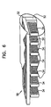
- Fig. 6 shows a coil assembly 50, in accordance with an alternative embodiment of the present invention.
- Assembly 50 comprises two photolithographic coils 52 similar to coil 10 of Fig. 1.
- coils 52 are aligned relative to each other in a manner similar to assembly 30.
- a plurality of small coils 54 are situated within a box shape defined by coils 52.
- Coils 54 are preferably similar to coils 52 although of smaller width and length, so that they fit in the box shape.
- Coils 54 are preferably connected in series.
- the small size of coils 54 is compensated for by the use of a number of coils.
- coils 54 are aligned such that they have a common axis, which is perpendicular to the axes of coils 52, forming together with coils 52 an assembly of three perpendicular sensors.
- Fig. 7 shows a catheter 70 including a photolithographic coil assembly 72, in accordance with a preferred embodiment of the present invention.
- Catheter 70 comprises an insertion tube 74, which is inserted into a patient's body.
- Coil assembly 72 is preferably a miniature assembly, similar to assembly 30 or 31, as described above, and is preferably situated adjacent the distal end of insertion tube 74.
- the coils in assembly 72 generate signals responsive to an external magnetic field applied thereto.
- a position determining system 80 coupled to coil assembly 72 receives the signals and accordingly determines position and orientation coordinates of the coil assembly and hence, the position and orientation of the catheter.
- the insertion tube of a catheter normally has a diameter of about 1-5 mm.
- a catheter having a round insertion tube of 3 mm diameter has a cross section of about 7 mm 2 .
- Assembly 72 has a cross section of about 0.6 mm 2 , thus taking up less than 10% of the cross sectional area of the catheter. Hence, assembly 72 does not substantially interfere with the operation of the catheter.
- assembly 72 is distanced from metallic and other substances in catheter 70 which may interfere with magnetic position determination, as described in the above-mentioned PCT/IL97/00061 patent application.
- the small width of assembly 72 allows larger separation from such interfering substances than other sensor assemblies.
- Endoscopes frequently comprise insertion tubes that include metallic substances. These insertion tubes normally have a diameter of about 12-15 mm. If the insertion tube has a metal core with a diameter of about 8 mm, it is possible to have over 2.5 mm separation between the metal core and coil assembly 72. Such separation is sufficient to reduce substantially interference caused by the metal core in position determination of the tube.
- assembly 72 may be inserted into existing catheters with relatively minimal change to the catheter's design.
Abstract
Description
- The present invention relates generally to object tracking systems, and specifically to non-contact, electromagnetic methods and devices for tracking the position and orientation of a medical probe.
- In many medical procedures, probes, such as endoscopes and catheters, are inserted into a patient's body. Such probes are used for a large variety of procedures including irreversible surgical actions, such as ablation and taking of tissue samples. Therefore, it is necessary to have accurate information on the position and orientation of the probe within the patient's body.
- Electromagnetic position determining systems provide a convenient method of receiving accurate information on the position and orientation of intra-body objects, and allow accurate tracking of these objects. Such systems are described for example in U.S. Patents 5,558,091, 5,391,199 and 5,443,489, and in International Patent Publications WO94/04938 and WO96/05768, whose disclosures are incorporated herein by reference. These systems determine the coordinates of a probe using one or more field sensors, such as a Hall effect device, coils or other antennas carried on the probe. The transducers are typically located at or adjacent the distal end of the probe, and/or along the length of the probe. Therefore, the transducers are preferably made as small as possible so as to fit into the probe without interfering with the probe's maneuverability or increasing its size unduly.
- U.S. Patent 5,558,091 describes a Hall effect sensor assembly of a cube shape which includes three mutually orthogonal, thin galvanomagnetic films. This sensor assembly is preferably of dimensions about 3 x 0.75 x 0.75 mm. The 5,558,091 Patent further describes another Hall effect sensor assembly which includes three field sensing elements in the form of semiconductor chips. Each chip includes one or more elongated bars of a magnetoresistive material. Each such chip is sensitive to magnetic field components in the direction of the bar. This assembly preferably has a diameter of 0.8 mm or less. However, such chips suffer from nonlinearities, saturation effects, hysteresis and temperature drifts.
- Therefore, most magnetic position determining systems use sensors formed of miniature coils that include a large number of turns of an electrically conducting wire. Such coils are described, for example, in PCT publications PCT/GB93/01736, WO94/04938 and WO96/05768, in the above mentioned U.S. Patent 5,391,199, and in PCT publication PCT/IL97/00009, which is assigned to the assignee of the present application, all of which are incorporated herein by reference. The performance of a sensor coil is dependent on its inductance, which is a function of the number of turns of the coil times the cross sectional area of the coil. Therefore, in planning a miniature coil for use within a surgical probe, for example, it is generally necessary to make a compromise between performance and the size of the coil. Such coils typically have minimum dimensions of 0.6 x 0.6 x 0.6 mm and more generally of 0.8 x 0.8 x 0.8 mm. Smaller coils of the same type would not provide acceptable performance and are also hard to manufacture.
- In order to determine both translational and rotational coordinates, some position determining systems, such as the system described in the above-mentioned PCT publication WO96/05768, use three sensor coils, having respective axes that are mutually linearly independent, preferably mutually orthogonal. Preferably, these three coils are packaged together to form a sensor assembly, which is used to provide six-dimensional position and orientation coordinate readings. The use of an assembly which has the three coils within one package allows easy insertion and/or attachment of the coils to catheters. Also, the assembly provides exact positioning of the coils relative to each other, thus simplifying the calibration of position determining systems using the coils. Generally, the coils are enclosed in a cylindrical-shaped case, which protects the coils from the surroundings.
- In the system of the '768 publication, this assembly typically has a length of about 6 mm and a diameter of about 1.3 mm. Because the axes of the coils need to be generally mutually orthogonal in order to achieve accurate position sensing in all six dimensions, it is not possible to make the diameter of the assembly much smaller.
- Although this coil assembly fits into most medical probes, in some cases coils of equivalent performance and smaller width are desired. For example, PCT patent application PCT/IL97/00061, which is assigned to the assignee of the present invention and is incorporated herein by reference, describes a method of enhancing the accuracy of position determination of an endoscope that includes miniature position sensing coils, by distancing the coils from metallic apparatus within the endoscope. If the coil assembly can be made with a smaller width, it is then possible to increase the separation between the miniature coils and the metallic apparatus, and thus achieve better accuracy from the position determining system.
- Reducing the width of the coil assembly also allows position determining systems to be used with narrower probes, which generally have superior maneuverability and ease of access to remote locations. Alternatively, reducing the width of the coil assembly allows the assembly to occupy a smaller portion of the cross-sectional area of the probe, leaving more space for functional apparatus and/or working channels along the probe.
- Coils made by photolithography or VLSI procedures are known in the art. In the following disclosure and in the claims, these coils are referred to as photolithographic coils. Photolithographic coils are generally made in the form of a spiral conductor printed on a substrate of plastic, ceramic or semiconductor material. Such coils conventionally comprise up to four overlapping spiral layers, using currently available fabrication techniques.
- Photolithographic coils or antennas are also commonly used in contactless smart cards, as are known in the art. These cards inductively communicate with and receive power from a reader circuit through a photolithographic coil or antenna embedded in the card. Because smart cards are limited in thickness to less than 0.8 mm, they generally include only a single coil, whose axis is necessarily perpendicular to the plane of the card. To communicate with the reader, the smart card must be properly oriented, so that the coil axis is aligned with a magnetic field generated by the reader, in order to achieve proper coupling.
- It is an object of some aspects of the present invention to provide a sensor coil with reduced thickness but high sensitivity and/or q-factor.
- It is another object of some aspects of the present invention to provide a coil assembly including three orthogonal coils having a narrow, elongate shape.
- In preferred embodiments of the present invention, a coil assembly comprises three coils of which at least one, and preferably two, comprise photolithographic coils. The coils have axes which are mutually linearly independent, preferably the axes are mutually substantially orthogonal. The use of these photolithographic coils allows forming coil assemblies with reduced diameter, width and/or depth, as described below.
- In some of these preferred embodiments, two of the coils comprise long, narrow photolithographic coils. The length of the coils compensate for the narrow width, so that the coil encompasses a large enough area to give sufficient inductance for use as a position sensor in a position determining system. Preferably, the width of the coil is less than 0.8 mm, most preferably less than 0.6 mm. The thickness of the coils is preferably limited only by the photolithographic process and is generally about 0.3 mm. In a preferred embodiment of the present invention, the photolithographic coils are produced on a flexible substrate, so that the assembly does not restrict the flexibility of a catheter carrying the assembly.
- In a preferred embodiment of the present invention, an assembly comprises two long, narrow photolithographic coils which are aligned with their long sides adjacent each other and substantially at 90° with respect to each other. Thus, the photolithographic coils define a long, narrow box shape, having a longitudinal axis to which the coil axes of the two photolithographic coils are substantially perpendicular.
- Preferably, the substrates of the photolithographic coils are cut diagonally at an angle of about 45°, so that the substrates are adjacent each other at the diagonal cuts. This connection saves space and minimizes the volume required by the assembly.
- The third coil, preferably a miniature wire-wound coil, is positioned with its coil axis along the longitudinal axis. Preferably, the third coil is outside and adjacent to the box shape, so that the width and depth of the assembly are substantially minimized. Alternatively, the diameter of the wire coil is smaller than the width of the photolithographic coils, and the wire coil is placed within the box shape defined by the photolithographic coils. Thus, the coil assembly has narrow width and depth, preferably smaller than 0.8 mm, most preferably about 0.6 mm, such that the diameter of a cylinder enclosing the assembly is no more than about 0.9 mm. Consequently, the cross-sectional area of the assembly is preferably less than 1 mm2, more preferably less than 0.8 mm2, and most preferably less than 0.65 mm2 .
- Preferably, a long, ellipsoidal ferrite core is contained inside the angle formed by the two photolithographic coils. Preferably, the wire coil is also wound around a core, most preferably around the long ellipsoidal core. The ferrite core enhances the inductance of the assembly and therefore the sensitivity of the coil assembly. Preferably the assembly is enclosed within a cylinder shaped case which protects the coils from the surroundings.
- In another preferred embodiment of the present invention, a plurality of small photolithographic coils are used to form the third coil. Preferably, the small coils are placed parallel each other, orthogonal to the first two coils, within the box shape defined by those coils, as described above. The small coils preferably have a rectangular shape with a width of about 0.4 mm, such that the small coils do not protrude from the box shape or from a cylinder encompassing the box shape. Alternatively, the plurality of photolithographic coils are placed outside the box shape of the first two coils but along the longitudinal axis thereof.
- In some preferred embodiments of the present invention, the coil assembly may comprise three photolithographic coils, the axes of which are mutually linearly independent.
- In some preferred embodiments of the present invention, one or more photolithographic coil assemblies, as described above, are placed within a medical probe to allow determination of coordinates of the probe, preferably six-dimensional position and orientation coordinates. In these assemblies, each coil preferably has a separate wire connection, so that the sensed effect of an external magnetic field on each coil is determined independently. A position determining system determines the position and orientation of the assembly based on the sensed effect on all three coils, as described, for example, in the above-mentioned WO96/05768 patent publication.
- Use of assemblies with photolithographic coils allows substantial decrease of the diameter of the cylinder encompassing the coils. This decreased diameter allows easier attachment or embedding of the assembly in the probe. A smaller assembly also makes it possible to use smaller probes, and/or reduces interference of the assembly with working channels and functional apparatus in the probe. Also, small width and thickness of the coil allow larger separation between the coil and metallic apparatus in the probe, thus minimizing interference with the operation of the position determining system.
- In other preferred embodiments of the present invention, a photolithographic coil assembly is used for inductive transfer of power and/or information. In these preferred embodiments, the three coils in the assembly are preferably connected together in series or in parallel. Such inductive information transfer is used, for example, in smart cards, as described above. The narrow width of the photolithographic coil assembly makes it especially suitable for use in smart cards, which generally must be no thicker than 0.8 mm. Using this coil assembly makes the coupling between the smart card and the reader substantially insensitive to the angle between the Smart Card and the reader, since the axes of the coil assembly are mutually linearly independent.
- Similarly, such photolithographic coil assemblies may be used in intrabody tube location confirmation devices, as described, for example, in a PCT Patent Application filed September 15, 1997, entitled "Position Confirmation with Learn and Test Functions," and filed as US patent application Serial No. 09/079,338 (applicant's docket no. BIO 0050.1 US) which is assigned to the assignee of the present invention and is incorporated herein by reference.
- There is therefore provided, in accordance with miniature coil assembly for transmitting or receiving magnetic waves including a plurality of coils, each coil having a respective axis, assembled such that at least two of the axes are mutually linearly independent, and such that all of the plurality of coils are contained within a volume having a cross-sectional area substantially less than 1.0 mm2, preferably substantially less than 0.8 mm2, and most preferably substantially less than 0.65 mm2.
- Preferably, at least two of the coils include photolithographic coils.
- There is further provided, in accordance with a preferred embodiment of the present invention, a miniature coil assembly for transmitting and receiving magnetic waves including two photolithographic coils having respective, mutually linearly independent axes.
- Preferably, the photolithographic coils have a width smaller than 0.8 mm, and more preferably smaller than 0.65 mm.
- Preferably, the axes of the two photolithographic coils are mutually substantially orthogonal.
- In a preferred embodiment of the invention, the assembly includes a third coil, wherein the axis of the third coil and of the two photolithographic coils are mutually linearly independent. Preferably, the axis of the third coil is substantially orthogonal to the axes of the two photolithographic coils.
- In one preferred embodiment, the third coil is a wire-wound coil, whereas in another preferred embodiment, the third coil includes a plurality of interconnected photolithographic circuits.
- Preferably, the two photolithographic coils include elongate rectangular substrates having a long side and a narrow side, and the two photolithographic coils are aligned such that the long sides of the two coils are mutually adjacent. Preferably, the substrates of the two photolithographic coils are aligned substantially at a right angle with respect to one another.
- Preferably, the assembly is circumscribed by a cylindrical volume having a diameter smaller than 1.1 mm, more preferably smaller than 0.9 mm.
- In a preferred embodiment, the assembly includes a ferromagnetic core for enhancing the inductance of the coils, preferably an elongate ellipsoidal ferrite. Preferably, the ferrite serves as a common core for substantially all of the coils in the assembly.
- Preferably, a position determining system receives signals generated by the coils responsive to an electromagnetic field and analyzes the signals to determine coordinates of the coils. Preferably, the coils are inserted in an invasive medical probe, for finding coordinates of the probe, preferably six-dimensional position and orientation coordinates.
- There is also provided, in accordance with a preferred embodiment of the present invention, a method for determining the position of an object including:
- attaching a photolithographic coil assembly to the object; and
- receiving signals from the assembly to determine coordinates thereof.
-
- Preferably, attaching the assembly includes embedding the photolithographic coils within the object.
- Further preferably, attaching the coil assembly includes fixing two photolithographic coils having respective axes to the object such that the axes of the two coils are mutually linearly independent, and so as to define a volume having a cross-sectional area substantially less than 1 mm2.
- There is additionally provided, in accordance with a preferred embodiment of the present invention, a probe whose position is tracked within the body of a subject, including:
- an insertion tube; and
- a photolithographic coil assembly attached to the insertion tube.
-
- Preferably, the assembly is contained within a volume having a cross-sectional area substantially less than 1.0 mm2.
- Further preferably, the photolithographic coil assembly includes at least two photolithographic coils and, preferably, a wire-wound coil, wherein the coils preferably have respective axes that are mutually linearly independent and, most preferably, mutually substantially orthogonal.
- In a preferred embodiment of the invention, a position determining system receives signals from the coils and analyzing the signals to determine coordinates of the probe.
- The present invention will be more fully understood from the following detailed description of the preferred embodiments thereof, taken together with the drawings, in which:
-
- Fig. 1 is a schematic perspective view of a photolithographic coil, in accordance with a preferred embodiment of the present invention;
- Fig. 2 is a schematic exploded view of the photolithographic coil of Fig. 1;
- Fig. 3 is a schematic, isometric view of a coil assembly, in accordance with a preferred embodiment of the present invention;
- Fig. 4 is a sectional view of the assembly of Fig. 3 taken along line IV-IV;
- Fig. 5 is a schematic, sectional view of a coil assembly, in accordance with a preferred embodiment of the present invention;
- Fig. 6 is a schematic, isometric view of a coil assembly, in accordance with a preferred embodiment of the present invention; and
- Fig. 7 is a schematic illustration of a catheter including a coil assembly, in accordance with a preferred embodiment of the present invention.
-
- Figs. 1 and 2 show a
sensor coil 10 made using a photolithographic method, in accordance with a preferred embodiment of the present invention. Fig. 1 shows a schematic view ofcoil 10, and Fig. 2 shows an exploded view ofcoil 10, which contains a plurality oflayers 18, ordinarily four, the number of which is limited practically by the limitations of current photolithographic technology. Eachlayer 18 contains a conductingspiral 12, which is deposited on asubstrate 14 of an electrically insulating material.External ports 16 positioned at the ends ofspiral 12 allow electric access tocoil 10, as is known in the art.Wires 26, which are connected toports 16,couple coil 10 to a position determining system or alternatively to a transmitter (not shown in the figures), which provides wireless transmission of signals to the position determining system. -
Substrate 14 preferably comprises a long, narrow, rectangular-shaped flat piece. Preferably,substrate 14 has a thickness of approximately 0.3 mm as is known in the art. The width (w) ofsubstrate 14 is approximately between 0.4 and 0.7 mm, preferably 0.6 mm. Preferably, the length (L1) ofsubstrate 14 is between about 4 and 5 mm. -
Spiral 12 contains a plurality ofloops 20 of diminishing size. Preferably,loops 20 are as large as possible, leaving only a minimal distance between each two adjacent loops, as required by VLSI technology rules, so as to encompass a maximal area.Spirals 12 of different layers are connected atvias 22, as is known in the art. -
Coil 10 is suitable for use as a near field sensor, especially for sensing electromagnetic fields alternating at a frequency between 1-5 kHz. - Fig. 3 shows a
coil assembly 30, in accordance with a preferred embodiment of the present invention.Assembly 30 comprises twophotolithographic coils 32, such ascoil 10 of Fig. 1, and awire coil 34.Wire coil 34 preferably has a diameter of about 0.8 mm and a length (L2) of about 1.4 mm, in which there are preferably about 400 turns.Coils 32 are aligned with their long sides adjacent each other and at approximately 90° with respect to each other, substantially defining a box shape. Preferably,wire coil 34 is positioned in a longitudinal extension of the box shape, so as not to add to the width or depth ofassembly 30. - Preferably,
wire coil 34 is wound around aferrite core 36, which enhances the inductance of the coil. More preferably,ferrite core 36 is long and narrow and is contained both withinwire coil 34 and within the box shape defined by coils 32. Thus,ferrite core 36 enhances the inductance of all of the coils inassembly 30. - Preferably,
assembly 30 is enclosed within acylindrical case 38, which has a diameter approximately equal to or slightly greater than a diagonal of the box shape defined byphotolithographic coils 32. - Fig. 4 shows a cross-section of the assembly of Fig. 3 taken along line IV-IV. Preferably, along a
common edge 33 betweencoils 32, the substrates of the coils are cut diagonally to reduce the volume taken up bycoil assembly 30. Alternatively, the substrates may be cut square, and one ofcoils 32 may be made wider than the other. - Fig. 5 shows a
coil assembly 31, in accordance with an alternative embodiment of the present invention.Assembly 31 is similar toassembly 30, except that inassembly 31,wire coil 34 is contained within the box shape defined byphotolithographic coils 32, and possibly extends therefrom intocase 38.Wire coil 34 has a diameter smaller than the width (w) ofcoils 32, preferably approximately 0.4 mm. In this embodiment,wire coil 34 preferably has between about 600 and 800 turns, in order to compensate for its small diameter. - It will be observed that
assembly 30 includes three substantially orthogonal coils, i.e., the axes of the coils are mutually substantially orthogonal. Therefore,assembly 30 may conveniently be used in apparatus such as a position determining system with six degrees of freedom. The size ofassembly 30 is limited bycoils 32, wherein its diameter is determined by the width (w) ofcoils 32, and the length ofassembly 30 is substantially the length (L1) ofcoils 32. - In a preferred embodiment of the present invention, not shown in the figures, a coil assembly such as
assembly 30 is embedded within a contactless smart card, for receiving power from and transferring information to a card reader. The coils of the assembly are preferably connected in series so that a magnetic field incident on the card induces a substantial current in the assembly, regardless of the orientation of the card relative to the field. Alternatively, the coils may be connected to each other in parallel. Due to the small dimensions of the assembly of the present invention, it is possible to insert it into conventional smart cards, which are typically limited in thickness to no more than about 0.8 mm. - Fig. 6 shows a
coil assembly 50, in accordance with an alternative embodiment of the present invention.Assembly 50 comprises twophotolithographic coils 52 similar tocoil 10 of Fig. 1. Preferably, coils 52 are aligned relative to each other in a manner similar toassembly 30. A plurality ofsmall coils 54 are situated within a box shape defined by coils 52.Coils 54 are preferably similar tocoils 52 although of smaller width and length, so that they fit in the box shape.Coils 54 are preferably connected in series. Thus, the small size ofcoils 54 is compensated for by the use of a number of coils. Preferably, coils 54 are aligned such that they have a common axis, which is perpendicular to the axes ofcoils 52, forming together withcoils 52 an assembly of three perpendicular sensors. - Fig. 7 shows a
catheter 70 including aphotolithographic coil assembly 72, in accordance with a preferred embodiment of the present invention.Catheter 70 comprises aninsertion tube 74, which is inserted into a patient's body.Coil assembly 72 is preferably a miniature assembly, similar toassembly insertion tube 74. As described, for example, in the above-mentioned PCT publication WO96/05768, the coils inassembly 72 generate signals responsive to an external magnetic field applied thereto. Aposition determining system 80 coupled tocoil assembly 72 receives the signals and accordingly determines position and orientation coordinates of the coil assembly and hence, the position and orientation of the catheter. - The insertion tube of a catheter normally has a diameter of about 1-5 mm. A catheter having a round insertion tube of 3 mm diameter has a cross section of about 7 mm2.
Assembly 72 has a cross section of about 0.6 mm2, thus taking up less than 10% of the cross sectional area of the catheter. Hence,assembly 72 does not substantially interfere with the operation of the catheter. - Preferably,
assembly 72 is distanced from metallic and other substances incatheter 70 which may interfere with magnetic position determination, as described in the above-mentioned PCT/IL97/00061 patent application. The small width ofassembly 72 allows larger separation from such interfering substances than other sensor assemblies. Endoscopes frequently comprise insertion tubes that include metallic substances. These insertion tubes normally have a diameter of about 12-15 mm. If the insertion tube has a metal core with a diameter of about 8 mm, it is possible to have over 2.5 mm separation between the metal core andcoil assembly 72. Such separation is sufficient to reduce substantially interference caused by the metal core in position determination of the tube. - It is noted that insertion of
assembly 72 into a catheter is simple and does not require any special design characteristics of the catheter. Thus,assembly 72 may be inserted into existing catheters with relatively minimal change to the catheter's design. - It will be appreciated that the preferred embodiments described above are cited by way of example, and the full scope of the invention is limited only by the claims.
Claims (10)
- A miniature coil assembly for transmitting or receiving magnetic waves comprising a plurality of coils, each coil having a respective axis, assembled such that at least two of the axes are mutually linearly independent, and such that all of the plurality of coils are contained within a volume having a cross-section area less than 1.0 mm2.
- The coil assembly of claim 1, wherein all of the plurality of coils are contained within a volume having a cross-section area less than 0.8 mm2, preferably less than 0.65 mm2.
- The assembly of claim 1 or claim 2, wherein the at least two of the coils comprise photolithographic coils.
- The assembly of claim 3, wherein the at least two photolithographic coils have respective, mutually linearly independent axes.
- The assembly of claim 4, wherein the axes of the two photolithographic coils are mutually substantially orthogonal.
- The assembly of claim 4 or claim 5, and comprising a third coil, wherein the axis of the third coil and of the two photolithographic coils are mutually linearly independent.
- The assembly of claim 6, wherein the axis of the third coil is substantially orthogonal to the axes of the two photolithographic coils.
- The coil assembly of claim 6 or claim 7, wherein the third coil is a wire-wound coil.
- The coil assembly of claim 6 or claim 7, wherein the third coil comprises a plurality of interconnected photolithographic circuits.
- The assembly of any one of claims 3 to 9, wherein the photolithographic coils have a width smaller than 0.8 mm, preferably smaller than 0.65 mm.
Applications Claiming Priority (2)
| Application Number | Priority Date | Filing Date | Title |
|---|---|---|---|
| US09/160,063 US6201387B1 (en) | 1997-10-07 | 1998-09-24 | Miniaturized position sensor having photolithographic coils for tracking a medical probe |
| US160063 | 1998-09-24 |
Publications (3)
| Publication Number | Publication Date |
|---|---|
| EP0989384A2 true EP0989384A2 (en) | 2000-03-29 |
| EP0989384A3 EP0989384A3 (en) | 2001-08-29 |
| EP0989384B1 EP0989384B1 (en) | 2005-11-16 |
Family
ID=22575364
Family Applications (1)
| Application Number | Title | Priority Date | Filing Date |
|---|---|---|---|
| EP99307530A Expired - Lifetime EP0989384B1 (en) | 1998-09-24 | 1999-09-23 | Miniaturized position sensor |
Country Status (8)
| Country | Link |
|---|---|
| US (1) | US6201387B1 (en) |
| EP (1) | EP0989384B1 (en) |
| JP (1) | JP4968979B2 (en) |
| AU (1) | AU755313B2 (en) |
| CA (1) | CA2283006C (en) |
| DE (1) | DE69928342T2 (en) |
| ES (1) | ES2251160T3 (en) |
| IL (1) | IL131807A (en) |
Cited By (16)
| Publication number | Priority date | Publication date | Assignee | Title |
|---|---|---|---|---|
| EP1169973A1 (en) | 2000-07-07 | 2002-01-09 | Biosense, Inc. | Bipolar mapping of intracardiac potentials |
| EP1169972A1 (en) | 2000-07-07 | 2002-01-09 | Biosense Webster, Inc. | Mapping and ablation catheter |
| EP1169975A1 (en) | 2000-07-07 | 2002-01-09 | Biosense Webster, Inc. | Catheter with tip electrode having a recessed ring electrode mounted thereon |
| EP1333368A2 (en) | 2001-12-26 | 2003-08-06 | Wacom Co., Ltd | Three-dimensional information detecting device, three-dimensional information detecting sensor device, and three-dimensional information indicating device |
| WO2006096685A1 (en) * | 2005-03-08 | 2006-09-14 | Kenergy, Inc. | Omnidirectional radio frequency signal receiving antenna for an implantable medical device |
| ES2273595A1 (en) * | 2005-09-19 | 2007-05-01 | Bsh Electrodomesticos España, S.A. | Method for establishing the positional coordinates of a metallic cooking vessel on a glass ceramic hob has a primary inductance coil and a pair of oppositely wound secondary coils beneath the surface |
| WO2013038354A1 (en) * | 2011-09-14 | 2013-03-21 | MediGuide, Ltd. | Method for producing a miniature electromagnetic coil using flexible printed circuitry |
| WO2015116687A1 (en) * | 2014-01-28 | 2015-08-06 | St. Jude Medical, Cardiology Division, Inc. | Elongate medical devices incorporating a flexible substrate, a sensor, and electrically-conductive traces |
| EP3199103A1 (en) * | 2014-01-28 | 2017-08-02 | St. Jude Medical, Cardiology Division, Inc. | Medical device with a packaged electronic subassembly and method for fabricating the same |
| CN108837274A (en) * | 2017-04-27 | 2018-11-20 | 韦伯斯特生物官能(以色列)有限公司 | Mechanical force snesor based on eddy current sensing |
| US10178960B2 (en) | 2013-02-11 | 2019-01-15 | St. Jude Medical, Atrial Fibrillation Division, Inc. | Printed electrode catheter |
| EP3479757A1 (en) * | 2017-11-07 | 2019-05-08 | Integrated Sensing Systems, Inc. | Implantable sensing devices and anchoring methods therefor |
| US10582833B2 (en) | 2014-11-18 | 2020-03-10 | Smith & Nephew, Inc. | Endocoupler with induction coupling |
| US10687709B2 (en) | 2016-05-09 | 2020-06-23 | Integrated Sensing Systems, Inc. | Implantable sensing devices and anchoring methods therefor |
| WO2020194212A1 (en) * | 2019-03-26 | 2020-10-01 | St. Jude Medical International Holding S.À R.L. | Off-axis magnetic position sensor assembly |
| US11116449B2 (en) | 2014-01-28 | 2021-09-14 | St. Jude Medical, Cardiology Division, Inc. | Catheter shaft with electrically-conductive traces |
Families Citing this family (177)
| Publication number | Priority date | Publication date | Assignee | Title |
|---|---|---|---|---|
| FR2652928B1 (en) | 1989-10-05 | 1994-07-29 | Diadix Sa | INTERACTIVE LOCAL INTERVENTION SYSTEM WITHIN A AREA OF A NON-HOMOGENEOUS STRUCTURE. |
| WO1994004938A1 (en) | 1992-08-14 | 1994-03-03 | British Telecommunications Public Limited Company | Position location system |
| US5803089A (en) | 1994-09-15 | 1998-09-08 | Visualization Technology, Inc. | Position tracking and imaging system for use in medical applications |
| US6226548B1 (en) | 1997-09-24 | 2001-05-01 | Surgical Navigation Technologies, Inc. | Percutaneous registration apparatus and method for use in computer-assisted surgical navigation |
| US6021343A (en) | 1997-11-20 | 2000-02-01 | Surgical Navigation Technologies | Image guided awl/tap/screwdriver |
| US6348058B1 (en) | 1997-12-12 | 2002-02-19 | Surgical Navigation Technologies, Inc. | Image guided spinal surgery guide, system, and method for use thereof |
| US6623473B1 (en) * | 1998-06-04 | 2003-09-23 | Biosense Webster, Inc. | Injection catheter with multi-directional delivery injection needle |
| US8079982B1 (en) | 1998-06-04 | 2011-12-20 | Biosense Webster, Inc. | Injection catheter with needle electrode |
| US6623474B1 (en) * | 1998-06-04 | 2003-09-23 | Biosense Webster, Inc. | Injection catheter with needle stop |
| US6477400B1 (en) | 1998-08-20 | 2002-11-05 | Sofamor Danek Holdings, Inc. | Fluoroscopic image guided orthopaedic surgery system with intraoperative registration |
| US6470207B1 (en) | 1999-03-23 | 2002-10-22 | Surgical Navigation Technologies, Inc. | Navigational guidance via computer-assisted fluoroscopic imaging |
| US6491699B1 (en) | 1999-04-20 | 2002-12-10 | Surgical Navigation Technologies, Inc. | Instrument guidance method and system for image guided surgery |
| US6493573B1 (en) | 1999-10-28 | 2002-12-10 | Winchester Development Associates | Method and system for navigating a catheter probe in the presence of field-influencing objects |
| US7366562B2 (en) | 2003-10-17 | 2008-04-29 | Medtronic Navigation, Inc. | Method and apparatus for surgical navigation |
| US11331150B2 (en) | 1999-10-28 | 2022-05-17 | Medtronic Navigation, Inc. | Method and apparatus for surgical navigation |
| US6474341B1 (en) | 1999-10-28 | 2002-11-05 | Surgical Navigation Technologies, Inc. | Surgical communication and power system |
| US6381485B1 (en) | 1999-10-28 | 2002-04-30 | Surgical Navigation Technologies, Inc. | Registration of human anatomy integrated for electromagnetic localization |
| US8644907B2 (en) | 1999-10-28 | 2014-02-04 | Medtronic Navigaton, Inc. | Method and apparatus for surgical navigation |
| US6499488B1 (en) | 1999-10-28 | 2002-12-31 | Winchester Development Associates | Surgical sensor |
| US8239001B2 (en) | 2003-10-17 | 2012-08-07 | Medtronic Navigation, Inc. | Method and apparatus for surgical navigation |
| WO2001064124A1 (en) | 2000-03-01 | 2001-09-07 | Surgical Navigation Technologies, Inc. | Multiple cannula image guided tool for image guided procedures |
| US6535756B1 (en) | 2000-04-07 | 2003-03-18 | Surgical Navigation Technologies, Inc. | Trajectory storage apparatus and method for surgical navigation system |
| US7085400B1 (en) | 2000-06-14 | 2006-08-01 | Surgical Navigation Technologies, Inc. | System and method for image based sensor calibration |
| US20040087877A1 (en) * | 2000-08-23 | 2004-05-06 | Besz William John | Catheter locator apparatus and method of use |
| EP1418845A4 (en) * | 2001-04-04 | 2006-06-07 | Given Imaging Ltd | Induction powered in vivo imaging device |
| US20030018251A1 (en) * | 2001-04-06 | 2003-01-23 | Stephen Solomon | Cardiological mapping and navigation system |
| US20040152974A1 (en) * | 2001-04-06 | 2004-08-05 | Stephen Solomon | Cardiology mapping and navigation system |
| US6636757B1 (en) | 2001-06-04 | 2003-10-21 | Surgical Navigation Technologies, Inc. | Method and apparatus for electromagnetic navigation of a surgical probe near a metal object |
| US6992477B2 (en) * | 2001-06-15 | 2006-01-31 | Biosense, Inc. | Medical device with position sensor having core with high permeability material for determining location coordinates of a portion of the medical device |
| US20030040670A1 (en) * | 2001-06-15 | 2003-02-27 | Assaf Govari | Method for measuring temperature and of adjusting for temperature sensitivity with a medical device having a position sensor |
| US7286868B2 (en) * | 2001-06-15 | 2007-10-23 | Biosense Inc. | Medical device with position sensor having accuracy at high temperatures |
| US6947786B2 (en) | 2002-02-28 | 2005-09-20 | Surgical Navigation Technologies, Inc. | Method and apparatus for perspective inversion |
| US6990368B2 (en) | 2002-04-04 | 2006-01-24 | Surgical Navigation Technologies, Inc. | Method and apparatus for virtual digital subtraction angiography |
| US7998062B2 (en) | 2004-03-29 | 2011-08-16 | Superdimension, Ltd. | Endoscope structures and techniques for navigating to a target in branched structure |
| US7560269B2 (en) * | 2002-12-20 | 2009-07-14 | Acea Biosciences, Inc. | Real time electronic cell sensing system and applications for cytotoxicity profiling and compound assays |
| US20040049121A1 (en) * | 2002-09-06 | 2004-03-11 | Uri Yaron | Positioning system for neurological procedures in the brain |
| US7599730B2 (en) | 2002-11-19 | 2009-10-06 | Medtronic Navigation, Inc. | Navigation system for cardiac therapies |
| US7697972B2 (en) | 2002-11-19 | 2010-04-13 | Medtronic Navigation, Inc. | Navigation system for cardiac therapies |
| US7660623B2 (en) | 2003-01-30 | 2010-02-09 | Medtronic Navigation, Inc. | Six degree of freedom alignment display for medical procedures |
| US7542791B2 (en) | 2003-01-30 | 2009-06-02 | Medtronic Navigation, Inc. | Method and apparatus for preplanning a surgical procedure |
| US7839146B2 (en) * | 2003-06-24 | 2010-11-23 | Medtronic, Inc. | Magnetic resonance imaging interference immune device |
| JP2005052637A (en) * | 2003-07-18 | 2005-03-03 | Pentax Corp | Capsule type device and capsule type device driving control system |
| US7354398B2 (en) * | 2003-07-18 | 2008-04-08 | Pentax Corporation | Capsule-type device and capsule-type device controlling system |
| US7313430B2 (en) | 2003-08-28 | 2007-12-25 | Medtronic Navigation, Inc. | Method and apparatus for performing stereotactic surgery |
| WO2005025635A2 (en) | 2003-09-15 | 2005-03-24 | Super Dimension Ltd. | System of accessories for use with bronchoscopes |
| EP2316328B1 (en) | 2003-09-15 | 2012-05-09 | Super Dimension Ltd. | Wrap-around holding device for use with bronchoscopes |
| US7835778B2 (en) * | 2003-10-16 | 2010-11-16 | Medtronic Navigation, Inc. | Method and apparatus for surgical navigation of a multiple piece construct for implantation |
| US7840253B2 (en) | 2003-10-17 | 2010-11-23 | Medtronic Navigation, Inc. | Method and apparatus for surgical navigation |
| EP1681010B1 (en) * | 2003-10-27 | 2012-10-10 | Olympus Corporation | Capsule type medical device |
| JP2005159607A (en) * | 2003-11-25 | 2005-06-16 | Matsushita Electric Ind Co Ltd | Portable communication apparatus |
| US8764725B2 (en) | 2004-02-09 | 2014-07-01 | Covidien Lp | Directional anchoring mechanism, method and applications thereof |
| US20070208252A1 (en) * | 2004-04-21 | 2007-09-06 | Acclarent, Inc. | Systems and methods for performing image guided procedures within the ear, nose, throat and paranasal sinuses |
| US7567834B2 (en) * | 2004-05-03 | 2009-07-28 | Medtronic Navigation, Inc. | Method and apparatus for implantation between two vertebral bodies |
| JP4476717B2 (en) * | 2004-06-30 | 2010-06-09 | オークマ株式会社 | Electromagnetic induction type position sensor |
| JP4508820B2 (en) * | 2004-10-19 | 2010-07-21 | 株式会社ワコム | 3D information detection system and 3D information input device |
| US7976518B2 (en) | 2005-01-13 | 2011-07-12 | Corpak Medsystems, Inc. | Tubing assembly and signal generator placement control device and method for use with catheter guidance systems |
| US7959601B2 (en) | 2005-02-14 | 2011-06-14 | Biosense Webster, Inc. | Steerable catheter with in-plane deflection |
| EP1920418A4 (en) | 2005-09-01 | 2010-12-29 | Proteus Biomedical Inc | Implantable zero-wire communications system |
| US7835784B2 (en) | 2005-09-21 | 2010-11-16 | Medtronic Navigation, Inc. | Method and apparatus for positioning a reference frame |
| US8862200B2 (en) * | 2005-12-30 | 2014-10-14 | DePuy Synthes Products, LLC | Method for determining a position of a magnetic source |
| US7525309B2 (en) | 2005-12-30 | 2009-04-28 | Depuy Products, Inc. | Magnetic sensor array |
| US20070161888A1 (en) * | 2005-12-30 | 2007-07-12 | Sherman Jason T | System and method for registering a bone of a patient with a computer assisted orthopaedic surgery system |
| US20070167741A1 (en) * | 2005-12-30 | 2007-07-19 | Sherman Jason T | Apparatus and method for registering a bone of a patient with a computer assisted orthopaedic surgery system |
| US7816915B2 (en) * | 2006-01-06 | 2010-10-19 | Biosense Webster, Inc. | Miniature coils on core with printed circuit |
| US9168102B2 (en) | 2006-01-18 | 2015-10-27 | Medtronic Navigation, Inc. | Method and apparatus for providing a container to a sterile environment |
| US7471202B2 (en) | 2006-03-29 | 2008-12-30 | General Electric Co. | Conformal coil array for a medical tracking system |
| US7532997B2 (en) | 2006-04-17 | 2009-05-12 | General Electric Company | Electromagnetic tracking using a discretized numerical field model |
| US8112292B2 (en) | 2006-04-21 | 2012-02-07 | Medtronic Navigation, Inc. | Method and apparatus for optimizing a therapy |
| DE102006029122A1 (en) * | 2006-06-22 | 2007-12-27 | Amedo Gmbh | System for determining the position of a medical instrument |
| FR2903812B1 (en) * | 2006-07-13 | 2008-10-31 | Commissariat Energie Atomique | INTEGRATED CIRCUIT DISTRIBUTED TO AT LEAST TWO NON-PARALLEL PLANS AND METHOD FOR PRODUCING THE SAME |
| US8172762B2 (en) * | 2006-09-01 | 2012-05-08 | Proteus Biomedical, Inc. | Simultaneous blood flow and hematocrit sensor |
| US8197494B2 (en) | 2006-09-08 | 2012-06-12 | Corpak Medsystems, Inc. | Medical device position guidance system with wireless connectivity between a noninvasive device and an invasive device |
| US8660635B2 (en) | 2006-09-29 | 2014-02-25 | Medtronic, Inc. | Method and apparatus for optimizing a computer assisted surgical procedure |
| AU2007350982A1 (en) | 2006-11-10 | 2008-10-23 | Dorian Averbuch | Adaptive navigation technique for navigating a catheter through a body channel or cavity |
| US8068648B2 (en) * | 2006-12-21 | 2011-11-29 | Depuy Products, Inc. | Method and system for registering a bone of a patient with a computer assisted orthopaedic surgery system |
| US20080167639A1 (en) * | 2007-01-08 | 2008-07-10 | Superdimension Ltd. | Methods for localized intra-body treatment of tissue |
| US7508195B2 (en) * | 2007-01-18 | 2009-03-24 | General Electric Company | Anti-distortion electromagnetic sensor method and system |
| US7573258B2 (en) * | 2007-01-18 | 2009-08-11 | General Electric Company | Coil arrangement for electromagnetic tracker method and system |
| JP5331307B2 (en) * | 2007-01-24 | 2013-10-30 | オリンパス株式会社 | Capsule endoscope and capsule endoscope system |
| JP2008178544A (en) * | 2007-01-24 | 2008-08-07 | Olympus Corp | Wireless feeding system, capsule endoscope and capsule endoscope system |
| US7782046B2 (en) * | 2007-02-05 | 2010-08-24 | General Electric Company | Electromagnetic tracking method and system |
| US8249689B2 (en) * | 2007-02-23 | 2012-08-21 | General Electric Company | Coil arrangement for electromagnetic tracking method and system |
| US7902817B2 (en) * | 2007-03-26 | 2011-03-08 | General Electric Company | Electromagnetic tracking method and system |
| US9055883B2 (en) * | 2007-05-16 | 2015-06-16 | General Electric Company | Surgical navigation system with a trackable ultrasound catheter |
| US8603046B2 (en) * | 2007-05-23 | 2013-12-10 | Biosense Webster, Inc. | Automated injection catheter device and system |
| US8192399B2 (en) * | 2007-05-23 | 2012-06-05 | Biosense Webster, Inc. | Extension control handle with adjustable locking mechanism |
| US8480653B2 (en) * | 2007-05-23 | 2013-07-09 | Biosense Webster, Inc. | Magnetically guided catheter with concentric needle port |
| US10292619B2 (en) * | 2007-07-09 | 2019-05-21 | Covidien Lp | Patient breathing modeling |
| US7834621B2 (en) * | 2007-09-25 | 2010-11-16 | General Electric Company | Electromagnetic tracking employing scalar-magnetometer |
| US8905920B2 (en) | 2007-09-27 | 2014-12-09 | Covidien Lp | Bronchoscope adapter and method |
| US8357152B2 (en) | 2007-10-08 | 2013-01-22 | Biosense Webster (Israel), Ltd. | Catheter with pressure sensing |
| US8535308B2 (en) * | 2007-10-08 | 2013-09-17 | Biosense Webster (Israel), Ltd. | High-sensitivity pressure-sensing probe |
| US8391952B2 (en) * | 2007-10-11 | 2013-03-05 | General Electric Company | Coil arrangement for an electromagnetic tracking system |
| US20090118620A1 (en) * | 2007-11-06 | 2009-05-07 | General Electric Company | System and method for tracking an ultrasound catheter |
| US8926511B2 (en) * | 2008-02-29 | 2015-01-06 | Biosense Webster, Inc. | Location system with virtual touch screen |
| US9575140B2 (en) | 2008-04-03 | 2017-02-21 | Covidien Lp | Magnetic interference detection system and method |
| US8218846B2 (en) * | 2008-05-15 | 2012-07-10 | Superdimension, Ltd. | Automatic pathway and waypoint generation and navigation method |
| EP2297673B1 (en) | 2008-06-03 | 2020-04-22 | Covidien LP | Feature-based registration method |
| US8437832B2 (en) * | 2008-06-06 | 2013-05-07 | Biosense Webster, Inc. | Catheter with bendable tip |
| US8218847B2 (en) | 2008-06-06 | 2012-07-10 | Superdimension, Ltd. | Hybrid registration method |
| US8932207B2 (en) | 2008-07-10 | 2015-01-13 | Covidien Lp | Integrated multi-functional endoscopic tool |
| US9101734B2 (en) * | 2008-09-09 | 2015-08-11 | Biosense Webster, Inc. | Force-sensing catheter with bonded center strut |
| US8165658B2 (en) | 2008-09-26 | 2012-04-24 | Medtronic, Inc. | Method and apparatus for positioning a guide relative to a base |
| JP5195336B2 (en) * | 2008-11-14 | 2013-05-08 | 株式会社ジェイテクト | Displacement sensor device and rolling bearing device |
| US8175681B2 (en) | 2008-12-16 | 2012-05-08 | Medtronic Navigation Inc. | Combination of electromagnetic and electropotential localization |
| US9326700B2 (en) | 2008-12-23 | 2016-05-03 | Biosense Webster (Israel) Ltd. | Catheter display showing tip angle and pressure |
| US8600472B2 (en) * | 2008-12-30 | 2013-12-03 | Biosense Webster (Israel), Ltd. | Dual-purpose lasso catheter with irrigation using circumferentially arranged ring bump electrodes |
| US8475450B2 (en) | 2008-12-30 | 2013-07-02 | Biosense Webster, Inc. | Dual-purpose lasso catheter with irrigation |
| DE102009022992A1 (en) * | 2009-03-02 | 2010-10-07 | Micro-Epsilon Messtechnik Gmbh & Co. Kg | position sensor |
| US8504139B2 (en) | 2009-03-10 | 2013-08-06 | Medtronic Xomed, Inc. | Navigating a surgical instrument |
| US9226689B2 (en) | 2009-03-10 | 2016-01-05 | Medtronic Xomed, Inc. | Flexible circuit sheet |
| US9226688B2 (en) | 2009-03-10 | 2016-01-05 | Medtronic Xomed, Inc. | Flexible circuit assemblies |
| US8611984B2 (en) | 2009-04-08 | 2013-12-17 | Covidien Lp | Locatable catheter |
| US8450997B2 (en) * | 2009-04-28 | 2013-05-28 | Brown University | Electromagnetic position and orientation sensing system |
| US8494613B2 (en) | 2009-08-31 | 2013-07-23 | Medtronic, Inc. | Combination localization system |
| US8494614B2 (en) | 2009-08-31 | 2013-07-23 | Regents Of The University Of Minnesota | Combination localization system |
| US9008574B2 (en) * | 2009-09-14 | 2015-04-14 | Qualcomm Incorporated | Focused antenna, multi-purpose antenna, and methods related thereto |
| US9101733B2 (en) * | 2009-09-29 | 2015-08-11 | Biosense Webster, Inc. | Catheter with biased planar deflection |
| JP6125231B2 (en) * | 2009-10-06 | 2017-05-17 | スミス アンド ネフュー インコーポレイテッド | Targeting orthopedic device landmarks |
| US10688278B2 (en) | 2009-11-30 | 2020-06-23 | Biosense Webster (Israel), Ltd. | Catheter with pressure measuring tip |
| US8920415B2 (en) | 2009-12-16 | 2014-12-30 | Biosense Webster (Israel) Ltd. | Catheter with helical electrode |
| US8521462B2 (en) | 2009-12-23 | 2013-08-27 | Biosense Webster (Israel), Ltd. | Calibration system for a pressure-sensitive catheter |
| US8529476B2 (en) | 2009-12-28 | 2013-09-10 | Biosense Webster (Israel), Ltd. | Catheter with strain gauge sensor |
| US8608735B2 (en) * | 2009-12-30 | 2013-12-17 | Biosense Webster (Israel) Ltd. | Catheter with arcuate end section |
| US8374670B2 (en) * | 2010-01-22 | 2013-02-12 | Biosense Webster, Inc. | Catheter having a force sensing distal tip |
| AU2011210257B2 (en) | 2010-02-01 | 2013-12-19 | Covidien Lp | Region-growing algorithm |
| CN105877844B (en) | 2010-04-30 | 2018-07-20 | 美敦力施美德公司 | The plasticity surgical instruments being navigated |
| US8798952B2 (en) | 2010-06-10 | 2014-08-05 | Biosense Webster (Israel) Ltd. | Weight-based calibration system for a pressure sensitive catheter |
| WO2011159834A1 (en) | 2010-06-15 | 2011-12-22 | Superdimension, Ltd. | Locatable expandable working channel and method |
| DE102010025379A1 (en) * | 2010-06-28 | 2011-12-29 | Technische Universität Dortmund | Method for detecting and warning of wrong-way drivers as well as wrong-way reporting and warning system |
| US8226580B2 (en) | 2010-06-30 | 2012-07-24 | Biosense Webster (Israel), Ltd. | Pressure sensing for a multi-arm catheter |
| US8380276B2 (en) | 2010-08-16 | 2013-02-19 | Biosense Webster, Inc. | Catheter with thin film pressure sensing distal tip |
| US8731859B2 (en) | 2010-10-07 | 2014-05-20 | Biosense Webster (Israel) Ltd. | Calibration system for a force-sensing catheter |
| US8979772B2 (en) | 2010-11-03 | 2015-03-17 | Biosense Webster (Israel), Ltd. | Zero-drift detection and correction in contact force measurements |
| US9974501B2 (en) | 2011-01-28 | 2018-05-22 | Medtronic Navigation, Inc. | Method and apparatus for image-based navigation |
| US10492868B2 (en) | 2011-01-28 | 2019-12-03 | Medtronic Navigation, Inc. | Method and apparatus for image-based navigation |
| US10617374B2 (en) | 2011-01-28 | 2020-04-14 | Medtronic Navigation, Inc. | Method and apparatus for image-based navigation |
| US8430864B2 (en) | 2011-02-16 | 2013-04-30 | Biosense Webster, Inc. | Catheter with multiple deflections |
| US8333103B2 (en) * | 2011-03-30 | 2012-12-18 | Biosense Webster (Israel), Ltd. | Calibration of a force measuring system for large bend angles of a catheter |
| US9220433B2 (en) | 2011-06-30 | 2015-12-29 | Biosense Webster (Israel), Ltd. | Catheter with variable arcuate distal section |
| US9662169B2 (en) | 2011-07-30 | 2017-05-30 | Biosense Webster (Israel) Ltd. | Catheter with flow balancing valve |
| WO2013036772A1 (en) | 2011-09-08 | 2013-03-14 | Corpak Medsystems, Inc. | Apparatus and method used with guidance system for feeding and suctioning |
| US9750486B2 (en) | 2011-10-25 | 2017-09-05 | Medtronic Navigation, Inc. | Trackable biopsy needle |
| US9427172B2 (en) | 2011-12-30 | 2016-08-30 | Mediguide Ltd. | Roll detection and six degrees of freedom sensor assembly |
| US9687289B2 (en) | 2012-01-04 | 2017-06-27 | Biosense Webster (Israel) Ltd. | Contact assessment based on phase measurement |
| US8929810B2 (en) | 2012-04-23 | 2015-01-06 | Qualcomm Incorporated | Methods and apparatus for improving NFC connection through device positioning |
| US10278729B2 (en) | 2013-04-26 | 2019-05-07 | Medtronic Xomed, Inc. | Medical device and its construction |
| US10952593B2 (en) | 2014-06-10 | 2021-03-23 | Covidien Lp | Bronchoscope adapter |
| US9603668B2 (en) | 2014-07-02 | 2017-03-28 | Covidien Lp | Dynamic 3D lung map view for tool navigation inside the lung |
| US20160000414A1 (en) | 2014-07-02 | 2016-01-07 | Covidien Lp | Methods for marking biopsy location |
| US9754367B2 (en) | 2014-07-02 | 2017-09-05 | Covidien Lp | Trachea marking |
| EP3164073B1 (en) | 2014-07-02 | 2020-07-01 | Covidien LP | System and method for detecting trachea |
| US9770216B2 (en) | 2014-07-02 | 2017-09-26 | Covidien Lp | System and method for navigating within the lung |
| CA2953146A1 (en) | 2014-07-02 | 2016-01-07 | Covidien Lp | System and method for segmentation of lung |
| WO2016004310A2 (en) | 2014-07-02 | 2016-01-07 | Covidien Lp | Real-time automatic registration feedback |
| US10426555B2 (en) | 2015-06-03 | 2019-10-01 | Covidien Lp | Medical instrument with sensor for use in a system and method for electromagnetic navigation |
| US10986990B2 (en) | 2015-09-24 | 2021-04-27 | Covidien Lp | Marker placement |
| US10709352B2 (en) | 2015-10-27 | 2020-07-14 | Covidien Lp | Method of using lung airway carina locations to improve ENB registration |
| US9962134B2 (en) | 2015-10-28 | 2018-05-08 | Medtronic Navigation, Inc. | Apparatus and method for maintaining image quality while minimizing X-ray dosage of a patient |
| US10478254B2 (en) | 2016-05-16 | 2019-11-19 | Covidien Lp | System and method to access lung tissue |
| US20190223758A1 (en) * | 2016-08-24 | 2019-07-25 | St. Jude Medical International Holding S.À R.L. | Composite planarity member with integrated tracking sensors |
| US10517505B2 (en) | 2016-10-28 | 2019-12-31 | Covidien Lp | Systems, methods, and computer-readable media for optimizing an electromagnetic navigation system |
| US10615500B2 (en) | 2016-10-28 | 2020-04-07 | Covidien Lp | System and method for designing electromagnetic navigation antenna assemblies |
| US10418705B2 (en) | 2016-10-28 | 2019-09-17 | Covidien Lp | Electromagnetic navigation antenna assembly and electromagnetic navigation system including the same |
| US10751126B2 (en) | 2016-10-28 | 2020-08-25 | Covidien Lp | System and method for generating a map for electromagnetic navigation |
| US10638952B2 (en) | 2016-10-28 | 2020-05-05 | Covidien Lp | Methods, systems, and computer-readable media for calibrating an electromagnetic navigation system |
| US10792106B2 (en) | 2016-10-28 | 2020-10-06 | Covidien Lp | System for calibrating an electromagnetic navigation system |
| US10446931B2 (en) | 2016-10-28 | 2019-10-15 | Covidien Lp | Electromagnetic navigation antenna assembly and electromagnetic navigation system including the same |
| US10722311B2 (en) | 2016-10-28 | 2020-07-28 | Covidien Lp | System and method for identifying a location and/or an orientation of an electromagnetic sensor based on a map |
| US10918306B2 (en) * | 2016-12-13 | 2021-02-16 | Biosense Webster (Israel) Ltd. | Catheter splines with embedded circuit elements |
| CN110446457A (en) * | 2017-02-01 | 2019-11-12 | 洛克西医疗设备有限责任公司 | For the flexible circuit of pill can be swallowed |
| US11304642B2 (en) * | 2017-02-15 | 2022-04-19 | Biosense Webster (Israel) Ltd. | Multi-axial position sensors printed on a folded flexible circuit board |
| WO2018150374A1 (en) * | 2017-02-17 | 2018-08-23 | St. Jude Medical International Holding S.À R.L. | Sensor coil assembly |
| US11219489B2 (en) | 2017-10-31 | 2022-01-11 | Covidien Lp | Devices and systems for providing sensors in parallel with medical tools |
| US10695109B2 (en) | 2017-12-13 | 2020-06-30 | DePuy Synthes Products, Inc. | Intramedullary nail with cannulation access hole |
| EP3740119A1 (en) * | 2018-01-16 | 2020-11-25 | Boston Scientific Scimed, Inc. | Electrical arrangements for sensor assemblies in electromagnetic navigation systems |
| US11224392B2 (en) | 2018-02-01 | 2022-01-18 | Covidien Lp | Mapping disease spread |
Citations (4)
| Publication number | Priority date | Publication date | Assignee | Title |
|---|---|---|---|---|
| US4245207A (en) * | 1977-05-20 | 1981-01-13 | Toko, Inc. | Miniature high frequency coil assembly or transformer |
| JPS59672A (en) * | 1982-06-27 | 1984-01-05 | Tsutomu Jinno | Distance measuring sensor |
| EP0444539A1 (en) * | 1990-03-02 | 1991-09-04 | Eta SA Fabriques d'Ebauches | Exciting coil set, method of fabricating the same and micromotor equipped therewith |
| US5729129A (en) * | 1995-06-07 | 1998-03-17 | Biosense, Inc. | Magnetic location system with feedback adjustment of magnetic field generator |
Family Cites Families (21)
| Publication number | Priority date | Publication date | Assignee | Title |
|---|---|---|---|---|
| US3868565A (en) | 1973-07-30 | 1975-02-25 | Jack Kuipers | Object tracking and orientation determination means, system and process |
| US4054881A (en) | 1976-04-26 | 1977-10-18 | The Austin Company | Remote object position locater |
| DE3230792C2 (en) | 1982-08-19 | 1986-10-23 | Nax GmbH & Co Ladenbau KG, 6000 Frankfurt | Refrigerated counter unit |
| US4613866A (en) | 1983-05-13 | 1986-09-23 | Mcdonnell Douglas Corporation | Three dimensional digitizer with electromagnetic coupling |
| US4642786A (en) | 1984-05-25 | 1987-02-10 | Position Orientation Systems, Ltd. | Method and apparatus for position and orientation measurement using a magnetic field and retransmission |
| DE3914619A1 (en) | 1989-05-03 | 1990-11-08 | Kontron Elektronik | DEVICE FOR TRANSOESOPHAGEAL ECHOCARDIOGRAPHY |
| EP0419729A1 (en) | 1989-09-29 | 1991-04-03 | Siemens Aktiengesellschaft | Position finding of a catheter by means of non-ionising fields |
| JP2750201B2 (en) | 1990-04-13 | 1998-05-13 | オリンパス光学工業株式会社 | Endoscope insertion state detection device |
| US5253647A (en) | 1990-04-13 | 1993-10-19 | Olympus Optical Co., Ltd. | Insertion position and orientation state pickup for endoscope |
| JP3441082B2 (en) * | 1990-05-31 | 2003-08-25 | 株式会社東芝 | Planar magnetic element |
| DE4117878C2 (en) * | 1990-05-31 | 1996-09-26 | Toshiba Kawasaki Kk | Planar magnetic element |
| GB9018660D0 (en) | 1990-08-24 | 1990-10-10 | Imperial College | Probe system |
| US5211165A (en) | 1991-09-03 | 1993-05-18 | General Electric Company | Tracking system to follow the position and orientation of a device with radiofrequency field gradients |
| US5425367A (en) | 1991-09-04 | 1995-06-20 | Navion Biomedical Corporation | Catheter depth, position and orientation location system |
| US5341807A (en) | 1992-06-30 | 1994-08-30 | American Cardiac Ablation Co., Inc. | Ablation catheter positioning system |
| WO1994004938A1 (en) | 1992-08-14 | 1994-03-03 | British Telecommunications Public Limited Company | Position location system |
| US5391199A (en) | 1993-07-20 | 1995-02-21 | Biosense, Inc. | Apparatus and method for treating cardiac arrhythmias |
| US5558091A (en) | 1993-10-06 | 1996-09-24 | Biosense, Inc. | Magnetic determination of position and orientation |
| DE4407785A1 (en) * | 1994-03-09 | 1995-09-14 | Philips Patentverwaltung | Arrangement for determining the spatial position of a scanning element displaceable relative to a reference element |
| US5786690A (en) * | 1994-08-18 | 1998-07-28 | International Business Machines Corporation | High resolution three-axis scanning squid microscope having planar solenoids |
| CA2197986C (en) | 1994-08-19 | 2008-03-18 | Shlomo Ben-Haim | Medical diagnosis, treatment and imaging systems |
-
1998
- 1998-09-24 US US09/160,063 patent/US6201387B1/en not_active Expired - Lifetime
-
1999
- 1999-09-08 IL IL13180799A patent/IL131807A/en not_active IP Right Cessation
- 1999-09-16 AU AU48768/99A patent/AU755313B2/en not_active Expired
- 1999-09-20 JP JP26568299A patent/JP4968979B2/en not_active Expired - Lifetime
- 1999-09-22 CA CA002283006A patent/CA2283006C/en not_active Expired - Lifetime
- 1999-09-23 ES ES99307530T patent/ES2251160T3/en not_active Expired - Lifetime
- 1999-09-23 DE DE69928342T patent/DE69928342T2/en not_active Expired - Lifetime
- 1999-09-23 EP EP99307530A patent/EP0989384B1/en not_active Expired - Lifetime
Patent Citations (5)
| Publication number | Priority date | Publication date | Assignee | Title |
|---|---|---|---|---|
| US4245207A (en) * | 1977-05-20 | 1981-01-13 | Toko, Inc. | Miniature high frequency coil assembly or transformer |
| JPS59672A (en) * | 1982-06-27 | 1984-01-05 | Tsutomu Jinno | Distance measuring sensor |
| US4560930A (en) * | 1982-06-27 | 1985-12-24 | Kono Tsutomu | Distance-measuring system using orthogonal magnetic field generators and orthogonal magnetic field sensors |
| EP0444539A1 (en) * | 1990-03-02 | 1991-09-04 | Eta SA Fabriques d'Ebauches | Exciting coil set, method of fabricating the same and micromotor equipped therewith |
| US5729129A (en) * | 1995-06-07 | 1998-03-17 | Biosense, Inc. | Magnetic location system with feedback adjustment of magnetic field generator |
Non-Patent Citations (1)
| Title |
|---|
| PATENT ABSTRACTS OF JAPAN vol. 008, no. 086 (P-269), 19 April 1984 (1984-04-19) & JP 59 000672 A (TSUTOMU JINNO), 5 January 1984 (1984-01-05) * |
Cited By (24)
| Publication number | Priority date | Publication date | Assignee | Title |
|---|---|---|---|---|
| EP1169973A1 (en) | 2000-07-07 | 2002-01-09 | Biosense, Inc. | Bipolar mapping of intracardiac potentials |
| EP1169972A1 (en) | 2000-07-07 | 2002-01-09 | Biosense Webster, Inc. | Mapping and ablation catheter |
| EP1169975A1 (en) | 2000-07-07 | 2002-01-09 | Biosense Webster, Inc. | Catheter with tip electrode having a recessed ring electrode mounted thereon |
| EP1333367A3 (en) * | 2001-12-26 | 2004-09-08 | Wacom Co., Ltd | Three-dimensional information detecting device, three-dimensional information detecting sensor device, and three-dimensional information indicating device |
| EP1333367A2 (en) * | 2001-12-26 | 2003-08-06 | Wacom Co., Ltd | Three-dimensional information detecting device, three-dimensional information detecting sensor device, and three-dimensional information indicating device |
| EP1333368A3 (en) * | 2001-12-26 | 2004-07-14 | Wacom Co., Ltd | Three-dimensional information detecting device, three-dimensional information detecting sensor device, and three-dimensional information indicating device |
| EP1333368A2 (en) | 2001-12-26 | 2003-08-06 | Wacom Co., Ltd | Three-dimensional information detecting device, three-dimensional information detecting sensor device, and three-dimensional information indicating device |
| WO2006096685A1 (en) * | 2005-03-08 | 2006-09-14 | Kenergy, Inc. | Omnidirectional radio frequency signal receiving antenna for an implantable medical device |
| US7532932B2 (en) * | 2005-03-08 | 2009-05-12 | Kenergy, Inc. | Implantable medical apparatus having an omnidirectional antenna for receiving radio frequency signals |
| ES2273595A1 (en) * | 2005-09-19 | 2007-05-01 | Bsh Electrodomesticos España, S.A. | Method for establishing the positional coordinates of a metallic cooking vessel on a glass ceramic hob has a primary inductance coil and a pair of oppositely wound secondary coils beneath the surface |
| WO2013038354A1 (en) * | 2011-09-14 | 2013-03-21 | MediGuide, Ltd. | Method for producing a miniature electromagnetic coil using flexible printed circuitry |
| CN103930024A (en) * | 2011-09-14 | 2014-07-16 | 麦迪盖德有限公司 | Method for producing a miniature electromagnetic coil using flexible printed circuitry |
| US10258255B2 (en) | 2011-09-14 | 2019-04-16 | St. Jude Medical International Holding S.àr.l. | Method for producing a miniature electromagnetic coil using flexible printed circuitry |
| US10178960B2 (en) | 2013-02-11 | 2019-01-15 | St. Jude Medical, Atrial Fibrillation Division, Inc. | Printed electrode catheter |
| WO2015116687A1 (en) * | 2014-01-28 | 2015-08-06 | St. Jude Medical, Cardiology Division, Inc. | Elongate medical devices incorporating a flexible substrate, a sensor, and electrically-conductive traces |
| EP3199103A1 (en) * | 2014-01-28 | 2017-08-02 | St. Jude Medical, Cardiology Division, Inc. | Medical device with a packaged electronic subassembly and method for fabricating the same |
| US10548671B2 (en) | 2014-01-28 | 2020-02-04 | St. Jude Medical International Holding S.á r.l. | Medical device with a packaged electronic subassembly and method for fabricating the same |
| US11116449B2 (en) | 2014-01-28 | 2021-09-14 | St. Jude Medical, Cardiology Division, Inc. | Catheter shaft with electrically-conductive traces |
| US10582833B2 (en) | 2014-11-18 | 2020-03-10 | Smith & Nephew, Inc. | Endocoupler with induction coupling |
| US11045070B2 (en) | 2014-11-18 | 2021-06-29 | Smith & Nephew, Inc. | Endocoupler with induction coupling |
| US10687709B2 (en) | 2016-05-09 | 2020-06-23 | Integrated Sensing Systems, Inc. | Implantable sensing devices and anchoring methods therefor |
| CN108837274A (en) * | 2017-04-27 | 2018-11-20 | 韦伯斯特生物官能(以色列)有限公司 | Mechanical force snesor based on eddy current sensing |
| EP3479757A1 (en) * | 2017-11-07 | 2019-05-08 | Integrated Sensing Systems, Inc. | Implantable sensing devices and anchoring methods therefor |
| WO2020194212A1 (en) * | 2019-03-26 | 2020-10-01 | St. Jude Medical International Holding S.À R.L. | Off-axis magnetic position sensor assembly |
Also Published As
| Publication number | Publication date |
|---|---|
| JP2000121306A (en) | 2000-04-28 |
| CA2283006C (en) | 2006-07-11 |
| AU755313B2 (en) | 2002-12-12 |
| IL131807A0 (en) | 2001-03-19 |
| IL131807A (en) | 2004-05-12 |
| JP4968979B2 (en) | 2012-07-04 |
| DE69928342D1 (en) | 2005-12-22 |
| ES2251160T3 (en) | 2006-04-16 |
| AU4876899A (en) | 2000-03-30 |
| US6201387B1 (en) | 2001-03-13 |
| CA2283006A1 (en) | 2000-03-24 |
| DE69928342T2 (en) | 2006-08-10 |
| EP0989384A3 (en) | 2001-08-29 |
| EP0989384B1 (en) | 2005-11-16 |
Similar Documents
| Publication | Publication Date | Title |
|---|---|---|
| EP0989384B1 (en) | Miniaturized position sensor | |
| EP1266614B1 (en) | Medical device with a position sensor | |
| EP1266613B1 (en) | Position sensor having core with high permeability material | |
| EP1806756B1 (en) | Miniature coils on core with printed circuit | |
| EP1266610A2 (en) | Method and system for measuring temperature and of adjusting for temperature sensitivity with a medical device having a position sensor | |
| US6615155B2 (en) | Object tracking using a single sensor or a pair of sensors | |
| US20100275934A1 (en) | Magnetic Method and System for Locating A Target | |
| AU2004203487A1 (en) | Encapsulated sensor with external antenna | |
| EP1269111A1 (en) | Object tracking using a single sensor or a pair of sensors |
Legal Events
| Date | Code | Title | Description |
|---|---|---|---|
| PUAI | Public reference made under article 153(3) epc to a published international application that has entered the european phase |
Free format text: ORIGINAL CODE: 0009012 |
|
| AK | Designated contracting states |
Kind code of ref document: A2 Designated state(s): AT BE CH CY DE DK ES FI FR GB GR IE IT LI LU MC NL PT SE |
|
| AX | Request for extension of the european patent |
Free format text: AL;LT;LV;MK;RO;SI |
|
| PUAL | Search report despatched |
Free format text: ORIGINAL CODE: 0009013 |
|
| AK | Designated contracting states |
Kind code of ref document: A3 Designated state(s): AT BE CH CY DE DK ES FI FR GB GR IE IT LI LU MC NL PT SE |
|
| AX | Request for extension of the european patent |
Free format text: AL;LT;LV;MK;RO;SI |
|
| 17P | Request for examination filed |
Effective date: 20020201 |
|
| AKX | Designation fees paid |
Free format text: DE ES FR GB IT NL |
|
| 17Q | First examination report despatched |
Effective date: 20040908 |
|
| RAP1 | Party data changed (applicant data changed or rights of an application transferred) |
Owner name: BIOSENSE WEBSTER, INC. |
|
| GRAP | Despatch of communication of intention to grant a patent |
Free format text: ORIGINAL CODE: EPIDOSNIGR1 |
|
| GRAS | Grant fee paid |
Free format text: ORIGINAL CODE: EPIDOSNIGR3 |
|
| GRAA | (expected) grant |
Free format text: ORIGINAL CODE: 0009210 |
|
| AK | Designated contracting states |
Kind code of ref document: B1 Designated state(s): DE ES FR GB IT NL |
|
| REG | Reference to a national code |
Ref country code: GB Ref legal event code: FG4D |
|
| REF | Corresponds to: |
Ref document number: 69928342 Country of ref document: DE Date of ref document: 20051222 Kind code of ref document: P |
|
| REG | Reference to a national code |
Ref country code: ES Ref legal event code: FG2A Ref document number: 2251160 Country of ref document: ES Kind code of ref document: T3 |
|
| ET | Fr: translation filed | ||
| PLBE | No opposition filed within time limit |
Free format text: ORIGINAL CODE: 0009261 |
|
| STAA | Information on the status of an ep patent application or granted ep patent |
Free format text: STATUS: NO OPPOSITION FILED WITHIN TIME LIMIT |
|
| 26N | No opposition filed |
Effective date: 20060817 |
|
| REG | Reference to a national code |
Ref country code: FR Ref legal event code: PLFP Year of fee payment: 18 |
|
| REG | Reference to a national code |
Ref country code: FR Ref legal event code: PLFP Year of fee payment: 19 |
|
| PGFP | Annual fee paid to national office [announced via postgrant information from national office to epo] |
Ref country code: ES Payment date: 20171002 Year of fee payment: 19 |
|
| REG | Reference to a national code |
Ref country code: FR Ref legal event code: PLFP Year of fee payment: 20 |
|
| PGFP | Annual fee paid to national office [announced via postgrant information from national office to epo] |
Ref country code: IT Payment date: 20180919 Year of fee payment: 20 Ref country code: DE Payment date: 20180911 Year of fee payment: 20 Ref country code: FR Payment date: 20180813 Year of fee payment: 20 |
|
| PGFP | Annual fee paid to national office [announced via postgrant information from national office to epo] |
Ref country code: NL Payment date: 20180912 Year of fee payment: 20 Ref country code: GB Payment date: 20180919 Year of fee payment: 20 |
|
| REG | Reference to a national code |
Ref country code: DE Ref legal event code: R071 Ref document number: 69928342 Country of ref document: DE |
|
| REG | Reference to a national code |
Ref country code: NL Ref legal event code: MK Effective date: 20190922 |
|
| REG | Reference to a national code |
Ref country code: GB Ref legal event code: PE20 Expiry date: 20190922 |
|
| REG | Reference to a national code |
Ref country code: ES Ref legal event code: FD2A Effective date: 20191031 |
|
| PG25 | Lapsed in a contracting state [announced via postgrant information from national office to epo] |
Ref country code: GB Free format text: LAPSE BECAUSE OF EXPIRATION OF PROTECTION Effective date: 20190922 |
|
| PG25 | Lapsed in a contracting state [announced via postgrant information from national office to epo] |
Ref country code: ES Free format text: LAPSE BECAUSE OF NON-PAYMENT OF DUE FEES Effective date: 20180924 |