EP0989424A2 - Fiber device having variable refractive index region proximal the core - Google Patents
Fiber device having variable refractive index region proximal the core Download PDFInfo
- Publication number
- EP0989424A2 EP0989424A2 EP99307245A EP99307245A EP0989424A2 EP 0989424 A2 EP0989424 A2 EP 0989424A2 EP 99307245 A EP99307245 A EP 99307245A EP 99307245 A EP99307245 A EP 99307245A EP 0989424 A2 EP0989424 A2 EP 0989424A2
- Authority
- EP
- European Patent Office
- Prior art keywords
- refractive index
- core
- vri
- region
- grating
- Prior art date
- Legal status (The legal status is an assumption and is not a legal conclusion. Google has not performed a legal analysis and makes no representation as to the accuracy of the status listed.)
- Withdrawn
Links
Images


Classifications
-
- G—PHYSICS
- G02—OPTICS
- G02B—OPTICAL ELEMENTS, SYSTEMS OR APPARATUS
- G02B6/00—Light guides; Structural details of arrangements comprising light guides and other optical elements, e.g. couplings
- G02B6/02—Optical fibres with cladding with or without a coating
- G02B6/036—Optical fibres with cladding with or without a coating core or cladding comprising multiple layers
- G02B6/03616—Optical fibres characterised both by the number of different refractive index layers around the central core segment, i.e. around the innermost high index core layer, and their relative refractive index difference
- G02B6/03638—Optical fibres characterised both by the number of different refractive index layers around the central core segment, i.e. around the innermost high index core layer, and their relative refractive index difference having 3 layers only
-
- G—PHYSICS
- G02—OPTICS
- G02B—OPTICAL ELEMENTS, SYSTEMS OR APPARATUS
- G02B6/00—Light guides; Structural details of arrangements comprising light guides and other optical elements, e.g. couplings
- G02B6/02—Optical fibres with cladding with or without a coating
-
- G—PHYSICS
- G02—OPTICS
- G02B—OPTICAL ELEMENTS, SYSTEMS OR APPARATUS
- G02B6/00—Light guides; Structural details of arrangements comprising light guides and other optical elements, e.g. couplings
- G02B6/02—Optical fibres with cladding with or without a coating
- G02B6/02057—Optical fibres with cladding with or without a coating comprising gratings
- G02B6/02076—Refractive index modulation gratings, e.g. Bragg gratings
- G02B6/02195—Refractive index modulation gratings, e.g. Bragg gratings characterised by means for tuning the grating
-
- G—PHYSICS
- G02—OPTICS
- G02B—OPTICAL ELEMENTS, SYSTEMS OR APPARATUS
- G02B6/00—Light guides; Structural details of arrangements comprising light guides and other optical elements, e.g. couplings
- G02B6/02—Optical fibres with cladding with or without a coating
- G02B6/036—Optical fibres with cladding with or without a coating core or cladding comprising multiple layers
- G02B6/03616—Optical fibres characterised both by the number of different refractive index layers around the central core segment, i.e. around the innermost high index core layer, and their relative refractive index difference
- G02B6/03622—Optical fibres characterised both by the number of different refractive index layers around the central core segment, i.e. around the innermost high index core layer, and their relative refractive index difference having 2 layers only
-
- G—PHYSICS
- G02—OPTICS
- G02B—OPTICAL ELEMENTS, SYSTEMS OR APPARATUS
- G02B6/00—Light guides; Structural details of arrangements comprising light guides and other optical elements, e.g. couplings
- G02B6/24—Coupling light guides
- G02B6/26—Optical coupling means
- G02B6/28—Optical coupling means having data bus means, i.e. plural waveguides interconnected and providing an inherently bidirectional system by mixing and splitting signals
- G02B6/293—Optical coupling means having data bus means, i.e. plural waveguides interconnected and providing an inherently bidirectional system by mixing and splitting signals with wavelength selective means
- G02B6/29304—Optical coupling means having data bus means, i.e. plural waveguides interconnected and providing an inherently bidirectional system by mixing and splitting signals with wavelength selective means operating by diffraction, e.g. grating
- G02B6/29316—Light guides comprising a diffractive element, e.g. grating in or on the light guide such that diffracted light is confined in the light guide
- G02B6/29317—Light guides of the optical fibre type
- G02B6/29319—With a cascade of diffractive elements or of diffraction operations
- G02B6/2932—With a cascade of diffractive elements or of diffraction operations comprising a directional router, e.g. directional coupler, circulator
-
- G—PHYSICS
- G02—OPTICS
- G02B—OPTICAL ELEMENTS, SYSTEMS OR APPARATUS
- G02B6/00—Light guides; Structural details of arrangements comprising light guides and other optical elements, e.g. couplings
- G02B6/24—Coupling light guides
- G02B6/26—Optical coupling means
- G02B6/28—Optical coupling means having data bus means, i.e. plural waveguides interconnected and providing an inherently bidirectional system by mixing and splitting signals
- G02B6/293—Optical coupling means having data bus means, i.e. plural waveguides interconnected and providing an inherently bidirectional system by mixing and splitting signals with wavelength selective means
- G02B6/29304—Optical coupling means having data bus means, i.e. plural waveguides interconnected and providing an inherently bidirectional system by mixing and splitting signals with wavelength selective means operating by diffraction, e.g. grating
- G02B6/29316—Light guides comprising a diffractive element, e.g. grating in or on the light guide such that diffracted light is confined in the light guide
- G02B6/29317—Light guides of the optical fibre type
- G02B6/29322—Diffractive elements of the tunable type
-
- G—PHYSICS
- G02—OPTICS
- G02B—OPTICAL ELEMENTS, SYSTEMS OR APPARATUS
- G02B6/00—Light guides; Structural details of arrangements comprising light guides and other optical elements, e.g. couplings
- G02B6/24—Coupling light guides
- G02B6/26—Optical coupling means
- G02B6/28—Optical coupling means having data bus means, i.e. plural waveguides interconnected and providing an inherently bidirectional system by mixing and splitting signals
- G02B6/293—Optical coupling means having data bus means, i.e. plural waveguides interconnected and providing an inherently bidirectional system by mixing and splitting signals with wavelength selective means
- G02B6/29379—Optical coupling means having data bus means, i.e. plural waveguides interconnected and providing an inherently bidirectional system by mixing and splitting signals with wavelength selective means characterised by the function or use of the complete device
- G02B6/29395—Optical coupling means having data bus means, i.e. plural waveguides interconnected and providing an inherently bidirectional system by mixing and splitting signals with wavelength selective means characterised by the function or use of the complete device configurable, e.g. tunable or reconfigurable
-
- G—PHYSICS
- G02—OPTICS
- G02B—OPTICAL ELEMENTS, SYSTEMS OR APPARATUS
- G02B6/00—Light guides; Structural details of arrangements comprising light guides and other optical elements, e.g. couplings
- G02B6/02—Optical fibres with cladding with or without a coating
- G02B6/02033—Core or cladding made from organic material, e.g. polymeric material
Definitions
- the present invention relates to fiber structures having one or more variable refractive index regions adjacent the core for index modulation.
- the fiber structure is particularly useful for tuning fiber filters including Bragg gratings and long-period gratings of optical communications systems.
- Optical fibers are well known in the art and useful for many applications in modern communications systems.
- a typical fiber optic communications system for example, is shown schematically in FIG. 1A, comprising a source of optical signals 10, a length of optical fiber 12 coupled to the source, and a receiver 14 coupled to the fiber for receiving the signals.
- One or more amplifying systems 16a, 16b may be disposed along the fiber for amplifying the transmitted signal. Filters are useful in these systems to change the power levels of various signals, especially in wavelength division multiplexed systems, along with signal modulation and wavelength routing.
- the optical fiber 12 shown in FIG. IA comprises an inner core fabricated from a dielectric material having a certain index of refraction, and a cladding surrounding the core.
- the cladding is comprised of a material having a lower index of refraction than the core.
- the refractive index of the core exceeds that ofthe cladding, a light beam propagated along the core exhibits total internal reflection, and it is guided along the length of the core. Since in the conventional optical fiber, light is confined mostly in the core region, the ability to externally effect propagation behavior of the light in the fiber is significantly limited. With conventional fibers, to change the propagation behavior of light in the core, one is essentially limited to the application of strain and/or temperature changes to the fiber.
- Optical fiber gratings including Bragg and long-period gratings are important elements for selectively controlling specific wavelengths of light within an optical fiber.
- Such Bragg gratings are useful in a variety of applications including filtering, stabilizing semiconductor lasers, reflecting fiber amplifier pump energy, and compensating for fiber dispersion.
- Bragg gratings in optical fibers are conveniently fabricated by providing a fiber having a core doped with one or more materials sensitive to ultraviolet light, such as a fiber having a core doped with germanium oxide, and then exposing the fiber at periodic intervals to high intensity ultraviolet light from an excimer laser.
- the ultraviolet light interacts with the photosensitive dopant to produce perturbations in the index of refraction.
- the appropriate periodic spacing of the perturbations to achieve a conventional grating can be obtained by use of a physical mask, a phase mask, or a pair of interfering beams.
- a tunable fiber grating has been attempted with use of a piezoelectric element to strain the grating. See Quetel et al., 1996 Technical Digest Series, Conf. on Optical Fiber Communication, San Jose, Calif, Feb. 25 - March 1, 1996, Vol. 2, p. 120, paper No. WF6.
- piezoelectric actuation is relatively small, limiting the tuning range of the device.
- piezoelectric activation requires a continuous application of relatively high voltage, e.g., approximately 100 volts for 1 nm strain.
- Another approach for providing a tunable Bragg grating involves use of thermally-induced strain on the fiber, as described in U.S. application Serial No. 08/957,953, "Device for Tuning Wavelength Response of an Optical Fiber Grating," filed October 27, 1997 by Fleming et al. (the '953 application), and assigned to the present assignee, which is incorporated herein by reference.
- the '953 application involves use of a temperature-sensitive body attached to the exterior of the optical fiber adjacent the Bragg grating region.
- Long-period fiber grating devices provide wavelength dependent loss and may be used for spectral shaping.
- a long-period grating couples optical power between two copropagating modes with very low back reflections.
- a long-period grating typically comprises a length of optical fiber wherein a plurality of refractive index perturbations are spaced along the fiber by a periodic distance ⁇ which is large compared to the wavelength ⁇ of the transmitted light.
- long-period gratings use a periodic spacing ⁇ which is typically at least 10 times larger than the transmitted wavelength, i.e. ⁇ ⁇ 10 ⁇ .
- A is in the range 15-1500 micrometers, and the width of a perturbation is in the range 1/5 ⁇ to 4/5 ⁇ .
- the spacing ⁇ can vary along the length of the grating.
- Long-period fiber grating devices selectively remove light at specific wavelengths by mode conversion.
- long-period gratings remove light without reflection by converting it from a guided mode to a non-guided mode.
- a non-guided mode is a mode which is not confined to the core, but rather, is defined by the entire waveguide structure. Often, it is a cladding mode.
- the spacing ⁇ of the perturbations is chosen to shift transmitted light in the region of a selected peak wavelength ⁇ p from a guided mode into a nonguided mode, thereby reducing in intensity a band of light centered about the peak wavelength ⁇ p .
- the spacing ⁇ can be chosen to shift light from one guided mode to a second guided mode (typically a higher order mode), which is substantially stripped to provide a wavelength dependent loss.
- Each long-period grating with a given periodicity ( ⁇ ) selectively filters light in a narrow bandwidth centered around the peak wavelength of coupling, ⁇ p .
- the values of n c and n cl are dependent on the relative values of the refractive indices of the core, cladding, and air.
- a difficulty with conventional long-period gratings is that their capability to equalize amplifier gain is limited, because they filter only a fixed wavelength acting as wavelength-dependent loss elements.
- a long-period grating whose transmission spectrum can be controlled. It is desirable to have a tunable (or reconfigurable) long-period grating which, upon activation, can be made to dynamically filter other wavelengths (i.e., besides ⁇ p .) Further, it is desirable to be able to selectively filter a broad range of wavelengths, e.g., for efficient operation of multiple-channel WDM in telecommunication systems.
- a recent device for providing a tunable long-period grating is described in U.S.
- the instant invention provides a new structure for a tunable optical fiber device, including a tunable Bragg or long-period grating device, that does not involve complicated structures or application of strain to the fiber.
- the invention embraces a tunable fiber device for use in a optical communications system comprising a length of fiber having a core fabricated with a material having a certain refractive index; a cladding surrounding the core with a refractive index less than the refractive index of the core; a grating region with periodic or quasi-periodic perturbations along a predetermined section of the length of the fiber; and at least one variable refractive index (VRI) region disposed within the cladding adjacent the grating region and in close proximity to the core.
- the VRI region has a refractive index lower than that of the core to modify the effective index of the mode propagated along the core. In modifying the effective index of the guided mode, the VRI region changes the wavelength filtered by the grating region and thereby provides a tunable grating device.
- the inventive device 20 may comprise part of an optical fiber communication system that further comprises elements such as a transmitter 10, a receiver 14, and an optical path 12 connecting transmitter and receiver, with one or more amplifiers 16a, 16b, disposed along the optical path.
- the device 20 may be placed at select regions of the optical path, and one or more devices 20 can be used in the optical system.
- FIG. 2 shows the device 20 in further detail providing an exploded, cross-sectional view at boxed region 2-2 of FIG. 1B.
- a fiber optic device useful for modifying the mode of light propagation can be fabricated by providing a length of fiber 22 where a predetermined section of the fiber, "s", contains one or more variable refractive index (VRI) regions 40.
- This section of the fiber "s" will be referred to herein as the VRI section.
- variable refractive index region it is meant that this region 40 is comprised of a material having a refractive index different than that of the core or the cladding and whose refractive index is capable of being varied either internally or externally, e.g., the "internal” variation comprising a variation occurring due to a change in the length, shape, or size of the VRI or due to a gradient over the width or length of the device such as with use of different concentrations of dopants, and the "external” variation comprising a variation occurring as a function of parameters such as time, temperature, or externally applied electric or magnetic fields.
- a grating region there are periodic or quasi-periodic perturbations within the core comprising a Bragg or long-period grating, as described above and as are known in the field.
- the grating region and the VRI region are positioned adjacent each, e.g., overlapping along the width of the fiber, for at least a portion of each of these regions.
- the opposite configuration may be used, that is, the length of the grating region "g" may be longer than and extend beyond the length of the VRI region.
- the regions may be substantially equal in length and overlap in an essentially complementary or coinciding fashion, which is preferred, or they may be staggered, the important consideration being that they overlap to at least some degree.
- the length of the fiber that does not include the VRI section is referred to herein as the standard fiber section.
- the interface regions where the VRI section is joined with the standard fiber section are referred to herein as the first and second connections 24a, 24b.
- the VRI region 40 is disposed in the cladding 30 of the fiber in close proximity to the core 32.
- close proximity to the core it is meant that at least a portion of at least one VRI region is sufficiently close to the core so that light is guided from the core into the VRI region.
- the distance from the center of the fiber to the outer edge of the VRI region proximal the core is less than or equal to one mode field diameter, which is known in the field.
- the distance "close proximity to the core” advantageously may be determined given that parameter.
- the VRI region changes the properties of the grating region and the wavelength of light filtered thereby, which may be modified or varied with appropriate selection of the materials used to fabricate the VRI region.
- the VRI region or regions may initially comprise air or holes which may later be filled with material of choice, or they may be doped with materials having different refractive indices than either the core or the cladding. Also, the VRI regions may have variable concentrations of dopants or be doped with different materials along their cross-sections to produce gradients of increasing or decreasing refractive indices.
- Dopants may include one or more of Ge, Al, B, P, Ga, La, and rare-earth dopants as described in U.S. Pat. No. 4,666,247 to MacChesney et al., "Multiconstituent Optical Fiber, " issued May 19, 1987 (the "247 patent"), assigned to the present assignee, which is hereby incorporated by reference.
- the degree of wavelength tuning effected by the VRI region may be controlled by altering the materials comprising the VRI region, by changing the length of the VRI section, by using temperature-sensitive materials or polymers for fabricating the VRI region and heating or cooling the fiber, by fabricating the VRI region with an electro-optic or magneto-optic material and applying an electric or magnetic field preferably adjacent the VRI section (e.g., with electrodes placed at the exterior of the fiber), or with use of other materials or methods for altering the index of the VRI region in the range from below the index of the core to near or below the index of the cladding.
- the VRI regions can be fabricated with materials that otherwise could not be incorporated within the fiber when drawn; in other words, materials that are unavailable for fabricating the cladding regions may be used to fabricate the VRI regions, which allows for a wide choice of material dispersion with these regions.
- the refractive index of the VRI region is not identical to the index of the cladding or the core.
- the VRI region In operation, if the VRI region has an index the same as that of the cladding, there is essentially no effect.
- the connections 24a, 24b may cause a small amount of insertion loss, but this loss is negligible, i.e., about less than 0.5 dB.
- the refractive index of the VRI should be kept lower than the refractive index of the core so that there is only one guided mode throughout the device; the refractive index of the VRI region may be below the index of the cladding. When the refractive index of the VRI is at least below that of the core, the effective index of the guided light (the reduction in the speed at which the light is transmitted in the fiber as compared with in a vacuum) is low.
- the effective index of the guided light is raised. Since the properties of the grating (e.g., the center wavelength filtered by the grating) are dependent on the effective index of the guided light, the wavelengths filtered by the grating will change as the refractive index of the VRI region is changed.
- the center wavelength of the grating may shift.
- the refractive index of the VRI region When the refractive index of the VRI region is raised or varied in a skewed, non-uniform manner over at least part of the length of the grating section, not only may the center wavelength of the grating shift but there also may be a chirp induced on the grating, changing the width and dispersion properties of the light guided by the fiber. As noted above, the degree of wavelength filtering may be altered by varying the constituents comprising the VRI regions.
- the inventive fiber device is thus advantageous for producing a tunable grating and is also advantageous for exhibiting little or no birefringence.
- the length of fiber has a core 32, surrounded by at least a first cladding layer 30.
- the core should be comprised of a material having a relatively high index of refraction, for example, a SiO 2 :GeO 2 core may be used, with GeO 2 being added to raise the refractive index. The index may also be raised with use of dopants, as previously discussed with reference to the VRI region and described in the '247 patent.
- the inner cladding 34 is comprised of a material having a lower index of refraction than the core, and may be undoped silicate glass.
- An optional second cladding 34 may surround the first inner cladding 30.
- the refractive indices of the layers would become progressively less moving from the core to the second cladding 34.
- a substantially circular outer polymer layer 48 optionally may be used if desired to protect the fiber.
- VRI regions 40 Within the inner cladding 34, adjacent the core 32, there are disposed one or more VRI regions 40. It is important that at least one of the variable refractive index regions be located in close proximity to the core, as defined above.
- the VRI regions may be formed in various shapes and have varying thicknesses, depending also on the dimensions of the fiber. The regions need not be symmetrical which is advantageous as this relaxes the processing conditions. Generally, VRI regions shaped substantially as circles or disks (e.g., as pie wedges with no "points"), are preferred as this eases the manufacturing steps. Preferably, more than two VRI regions are used so that there are no distinctly different axes located 90 degrees apart, as this reduces the likelihood of there being fundamental mode birefringence associated with the VRI regions. Manufacturing the inventive fiber device with a plurality of regions (e.g., from three to six or more) around the core is not substantially more difficult than making the device with just two VRI regions.
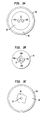
- the VRI regions may comprise essentially one or more amorphous rods 42a, 42b, as shown in FIG. 3A, on either side of the core 32.
- the regions may comprise a plurality of substantially non-circular isolated regions 44a, 44b, 44c, 44d, suspended within the cladding 30, as shown in Fig. 3B.
- the VRI region may comprise a substantially non-circular region 46 concentrically surrounding the core as in Fig. 3C.
- the VRI regions can be amorphous, without any clearly defined shape, thereby avoiding manufacturing difficulties associated with obtaining a particular configuration.
- the VRI regions can be produced by selective diffusion or implantation of dopants in the cladding, applying doping techniques known in the field. These regions also may be fabricated with materials that are responsive to electric or magnetic fields or temperature, such as liquid crystals or certain polymers, and then the refractive indices of the VRI regions may be adjusted by selectively applying magnetic or electric fields or heating or cooling the fiber.
- a straightforward method of making the optical fiber device comprising the VRI section involves providing a portion of a fiber having a Bragg or long period grating region and holes disposed along its length adjacent the core in the area of the grating. Refractive index oil, such as oil manufactured by Cargille Inc. of Cedar Grove, NJ, or other liquid materials may be easily drawn into the holes by capillary action.
- a vacuum pump may be used.
- a section of the holes adjacent the interfaces 24a, 24b preferably should be left hollow to ease the process of joining the VRI section to the standard fiber section.
- a solid refractive index material is used to form the VRI region, preferably the VRI is formed during the processing of the fiber itself.
- inventive device may be used in a variety of applications and optical communications systems, such as wavelength division multiplexer/demultiplexer devices including devices with ADD/DROP functionality.
- the tunable grating device may be coupled to a wavelength device and feedback system such that the tuning of the device may be automatically controlled.
- FIG. 4 illustrates one such application of the invention comprising an N channel add/drop wavelength-division multiplexed (WDM) communication system with two circulators and one or more inventive gratings.
- WDM communications system comprises a transmitter 70, an improved N-channel multiplexer/demultiplexer within boxed region 71, and a receiver 72, all connected by trunk fiber 11.
- the input to the fiber 11 from the source 70 consists of optical signals at several wavelengths, ⁇ 1 to ⁇ n .
- the improved multiplexer 71 comprises one or more pairs (one pair is shown) of circulators 73, 74, comprising at least one upstream circulator 73 and a downstream circulator 74.
- a series of inventive gratings (10a, 10b, 10c, 10d, ... 10n) are placed between the circulators.
- One or more of the optical grating devices 10a .... 10n may be activated to drop or add communication channels of selected wavelengths, ⁇ 1 , ⁇ 2 , ⁇ 3 , ⁇ 4 , ... to ⁇ n .
Abstract
Description
- This application is related to U.S. application Serial No. , filed concomitantly herewith, titled "Fiber Device Having Variable Refractive Index Region Proximal the Core," by the same inventive entity herein and assigned to the present assignee.
- The present invention relates to fiber structures having one or more variable refractive index regions adjacent the core for index modulation. The fiber structure is particularly useful for tuning fiber filters including Bragg gratings and long-period gratings of optical communications systems.
- Optical fibers are well known in the art and useful for many applications in modern communications systems. A typical fiber optic communications system, for example, is shown schematically in FIG. 1A, comprising a source of
optical signals 10, a length ofoptical fiber 12 coupled to the source, and areceiver 14 coupled to the fiber for receiving the signals. One or moreamplifying systems - Basically, the
optical fiber 12 shown in FIG. IA comprises an inner core fabricated from a dielectric material having a certain index of refraction, and a cladding surrounding the core. The cladding is comprised of a material having a lower index of refraction than the core. As long as the refractive index of the core exceeds that ofthe cladding, a light beam propagated along the core exhibits total internal reflection, and it is guided along the length of the core. Since in the conventional optical fiber, light is confined mostly in the core region, the ability to externally effect propagation behavior of the light in the fiber is
significantly limited. With conventional fibers, to change the propagation behavior of light in the core, one is essentially limited to the application of strain and/or temperature changes to the fiber. - Optical fiber gratings including Bragg and long-period gratings are important elements for selectively controlling specific wavelengths of light within an optical fiber. A typical Bragg grating comprises a length of optical fiber including a plurality of perturbations in the index of refraction substantially equally spaced along the fiber length. These perturbations selectively reflect light of wavelength λ equal to twice the spacing Λ between successive perturbations, i.e. λ=2neffΛ, where λ is the vacuum wavelength and neff is the effective refractive index of the propagating mode. Light of the selected wavelength λ is reflected back to point of origin, and the remaining wavelengths pass essentially unimpeded. Such Bragg gratings are useful in a variety of applications including filtering, stabilizing semiconductor lasers, reflecting fiber amplifier pump energy, and compensating for fiber dispersion.
- Bragg gratings in optical fibers are conveniently fabricated by providing a fiber having a core doped with one or more materials sensitive to ultraviolet light, such as a fiber having a core doped with germanium oxide, and then exposing the fiber at periodic intervals to high intensity ultraviolet light from an excimer laser. The ultraviolet light interacts with the photosensitive dopant to produce perturbations in the index of refraction. The appropriate periodic spacing of the perturbations to achieve a conventional grating can be obtained by use of a physical mask, a phase mask, or a pair of interfering beams.
- A difficulty with conventional fiber Bragg gratings is that they filter only a fixed wavelength. Each grating selectively reflects light in only a narrow bandwidth centered around λ=2neffΛ. However, in many applications, such as multiplexing, it is desirable to have a grating whose wavelength response can be tuned, that is, controllably altered. A tunable fiber grating has been attempted with use of a piezoelectric element to strain the grating. See Quetel et al., 1996 Technical Digest Series, Conf. on Optical Fiber Communication, San Jose, Calif, Feb. 25 - March 1, 1996, Vol. 2, p. 120, paper No. WF6. However, the strain produced by piezoelectric actuation is relatively small, limiting the tuning range of the device. Moreover, piezoelectric activation requires a continuous application of relatively high voltage, e.g., approximately 100 volts for 1 nm strain. Another approach for providing a tunable Bragg grating involves use of thermally-induced strain on the fiber, as described in U.S. application Serial No. 08/957,953, "Device for Tuning Wavelength Response of an Optical Fiber Grating," filed October 27, 1997 by Fleming et al. (the '953 application), and assigned to the present assignee, which is incorporated herein by reference. The '953 application involves use of a temperature-sensitive body attached to the exterior of the optical fiber adjacent the Bragg grating region.
- Long-period fiber grating devices provide wavelength dependent loss and may be used for spectral shaping. A long-period grating couples optical power between two copropagating modes with very low back reflections. A long-period grating typically comprises a length of optical fiber wherein a plurality of refractive index perturbations are spaced along the fiber by a periodic distance Λ which is large compared to the wavelength λ of the transmitted light. In contrast with conventional Bragg gratings, long-period gratings use a periodic spacing Λ which is typically at least 10 times larger than the transmitted wavelength, i.e. Λ ≥ 10λ. Typically A is in the range 15-1500 micrometers, and the width of a perturbation is in the range 1/5Λ to 4/5Λ. In some applications, such as chirped gratings, the spacing Λ can vary along the length of the grating.
- Long-period fiber grating devices selectively remove light at specific wavelengths by mode conversion. In contrast with conventional Bragg gratings in which light is reflected and stays in the fiber core, long-period gratings remove light without reflection by converting it from a guided mode to a non-guided mode. A non-guided mode is a mode which is not confined to the core, but rather, is defined by the entire waveguide structure. Often, it is a cladding mode. The spacing Λ of the perturbations is chosen to shift transmitted light in the region of a selected peak wavelength λp from a guided mode into a nonguided mode, thereby reducing in intensity a band of light centered about the peak wavelength λp. Alternatively, the spacing Λ can be chosen to shift light from one guided mode to a second guided mode (typically a higher order mode), which is substantially stripped to provide a wavelength dependent loss.
- Long-period grating devices are thus useful as filtering and spectral shaping devices in a variety of optical communications applications. Each long-period grating with a given periodicity (Λ) selectively filters light in a narrow bandwidth centered around the peak wavelength of coupling, λp. This wavelength is determined by λp = (nc-ncl) • Λ, where ng and nng denote the effective index of the core mode and the cladding mode, respectively. The values of nc and ncl are dependent on the relative values of the refractive indices of the core, cladding, and air. A difficulty with conventional long-period gratings, however, is that their capability to equalize amplifier gain is limited, because they filter only a fixed wavelength acting as wavelength-dependent loss elements. Thus, there is a need for a long-period grating whose transmission spectrum can be controlled. It is desirable to have a tunable (or reconfigurable) long-period grating which, upon activation, can be made to dynamically filter other wavelengths (i.e., besides λp.) Further, it is desirable to be able to selectively filter a broad range of wavelengths, e.g., for efficient operation of multiple-channel WDM in telecommunication systems. A recent device for providing a tunable long-period grating is described in U.S. application Serial No. 08/957,956, "Tunable Long-Period Grating Device and Optical Systems Employing Same," filed October 27, 1997 by Jin et al. (the '956 application), and assigned to the present assignee, which is incorporated herein by reference. The '953 application involves use of a strain-inducing body secured to the fiber adjacent the grating region for changing the spacing between the perturbations of the grating.
- As may be appreciated, those concerned with the development of optical communications systems and, more particularly fiber devices, continually search for new components and fiber designs. As optical communications systems become more advanced, there is growing interest in increasing the number of wavelengths that may be transmitted by the systems and therefore in new methods and devices for modulating, filtering, and switching wavelength channels. The instant invention provides a new structure for a tunable optical fiber device, including a tunable Bragg or long-period grating device, that does not involve complicated structures or application of strain to the fiber.
- Summarily described, the invention embraces a tunable fiber device for use in a optical communications system comprising a length of fiber having a core fabricated with a material having a certain refractive index; a cladding surrounding the core with a refractive index less than the refractive index of the core; a grating region with periodic or quasi-periodic perturbations along a predetermined section of the length of the fiber; and at least one variable refractive index (VRI) region disposed within the cladding adjacent the grating region and in close proximity to the core. The VRI region has a refractive index lower than that of the core to modify the effective index of the mode propagated along the core. In modifying the effective index of the guided mode, the VRI region changes the wavelength filtered by the grating region and thereby provides a tunable grating device.
- For a better understanding of the invention, an exemplary embodiment is described below, considered together with the accompanying drawings, in which:
- FIG. 1A shows a schematic illustration of an optical communications system;
- FIG. 1B is a schematic illustration of an optical communications system including the inventive device;
- FIG. 2 shows a cross-sectional view of one embodiment of an inventive fiber grating device taken along the length;
- FIGS. 3A, 3B, and 3C show cross-sectional views of alternate embodiments of the inventive fiber device, taken along a cross-sectional width following the line 3-3 of FIG. 2; and
- FIG. 4 illustrates an application of the invention comprising an N channel add/drop WDM communication system with two circulators and one or more gratings according to the invention.
-
- It is to be understood that these drawings are for the purposes of illustrating the concepts of the invention and are not to scale.
- Referring to FIG. 1B, it will be appreciated that the
inventive device 20 may comprise part of an optical fiber communication system that further comprises elements such as atransmitter 10, areceiver 14, and anoptical path 12 connecting transmitter and receiver, with one ormore amplifiers device 20 may be placed at select regions of the optical path, and one ormore devices 20 can be used in the optical system. FIG. 2 shows thedevice 20 in further detail providing an exploded, cross-sectional view at boxed region 2-2 of FIG. 1B. - Referring to FIG. 2, applicants have discovered that a fiber optic device useful for modifying the mode of light propagation can be fabricated by providing a length of fiber 22 where a predetermined section of the fiber, "s", contains one or more variable refractive index (VRI) regions 40. This section of the fiber "s" will be referred to herein as the VRI section. By "variable refractive index region" it is meant that this region 40 is comprised of a material having a refractive index different than that of the core or the cladding and whose refractive index is capable of being varied either internally or externally, e.g., the "internal" variation comprising a variation occurring due to a change in the length, shape, or size of the VRI or due to a gradient over the width or length of the device such as with use of different concentrations of dopants, and the "external" variation comprising a variation occurring as a function of parameters such as time, temperature, or externally applied electric or magnetic fields.
- Also, along the length of the fiber there is disposed a predetermined section containing a grating region "g." At the grating region there are periodic or quasi-periodic perturbations within the core comprising a Bragg or long-period grating, as described above and as are known in the field. The grating region and the VRI region are positioned adjacent each, e.g., overlapping along the width of the fiber, for at least a portion of each of these regions. Although in FIG. 2 the device is shown where the VRI region is longer than and spans the width of the grating region and beyond, the opposite configuration may be used, that is, the length of the grating region "g" may be longer than and extend beyond the length of the VRI region. Other configurations are also possible, e.g., the regions may be substantially equal in length and overlap in an essentially complementary or coinciding fashion, which is preferred, or they may be staggered, the important consideration being that they overlap to at least some degree.
- The length of the fiber that does not include the VRI section is referred to herein as the standard fiber section. The interface regions where the VRI section is joined with the standard fiber section are referred to herein as the first and
second connections cladding 30 of the fiber in close proximity to thecore 32. By "close proximity to the core" it is meant that at least a portion of at least one VRI region is sufficiently close to the core so that light is guided from the core into the VRI region. Preferably, the distance from the center of the fiber to the outer edge of the VRI region proximal the core is less than or equal to one mode field diameter, which is known in the field. The distance "close proximity to the core" advantageously may be determined given that parameter. The VRI region changes the properties of the grating region and the wavelength of light filtered thereby, which may be modified or varied with appropriate selection of the materials used to fabricate the VRI region. - The VRI region or regions may initially comprise air or holes which may later be filled with material of choice, or they may be doped with materials having different refractive indices than either the core or the cladding. Also, the VRI regions may have variable concentrations of dopants or be doped with different materials along their cross-sections to produce gradients of increasing or decreasing refractive indices. Dopants may include one or more of Ge, Al, B, P, Ga, La, and rare-earth dopants as described in U.S. Pat. No. 4,666,247 to MacChesney et al., "Multiconstituent Optical Fiber, " issued May 19, 1987 (the "247 patent"), assigned to the present assignee, which is hereby incorporated by reference. The degree of wavelength tuning effected by the VRI region may be controlled by altering the materials comprising the VRI region, by changing the length of the VRI section, by using temperature-sensitive materials or polymers for fabricating the VRI region and heating or cooling the fiber, by fabricating the VRI region with an electro-optic or magneto-optic material and applying an electric or magnetic field preferably adjacent the VRI section (e.g., with electrodes placed at the exterior of the fiber), or with use of other materials or methods for altering the index of the VRI region in the range from below the index of the core to near or below the index of the cladding. The VRI regions can be fabricated with materials that otherwise could not be incorporated within the fiber when drawn; in other words, materials that are unavailable for fabricating the cladding regions may be used to fabricate the VRI regions, which allows for a wide choice of material dispersion with these regions. Preferably, the refractive index of the VRI region is not identical to the index of the cladding or the core.
- In operation, if the VRI region has an index the same as that of the cladding, there is essentially no effect. The
connections - Referring to FIGS. 3A through 3C, there are shown cross-sectional views of alternative embodiments of the inventive device, taken along the width at the cross-sectional line 3-3 of FIG. 2. The length of fiber has a core 32, surrounded by at least a
first cladding layer 30. The core should be comprised of a material having a relatively high index of refraction, for example, a SiO2:GeO2 core may be used, with GeO2 being added to raise the refractive index. The index may also be raised with use of dopants, as previously discussed with reference to the VRI region and described in the '247 patent. Theinner cladding 34 is comprised of a material having a lower index of refraction than the core, and may be undoped silicate glass. - An optional
second cladding 34 may surround the firstinner cladding 30. Thus, the refractive indices of the layers would become progressively less moving from the core to thesecond cladding 34. However, use of a second cladding layer is not needed to practice this invention. A substantially circular outer polymer layer 48 optionally may be used if desired to protect the fiber. - Within the
inner cladding 34, adjacent thecore 32, there are disposed one or more VRI regions 40. It is important that at least one of the variable refractive index regions be located in close proximity to the core, as defined above. The VRI regions may be formed in various shapes and have varying thicknesses, depending also on the dimensions of the fiber. The regions need not be symmetrical which is advantageous as this relaxes the processing conditions. Generally, VRI regions shaped substantially as circles or disks (e.g., as pie wedges with no "points"), are preferred as this eases the manufacturing steps. Preferably, more than two VRI regions are used so that there are no distinctly different axes located 90 degrees apart, as this reduces the likelihood of there being fundamental mode birefringence associated with the VRI regions. Manufacturing the inventive fiber device with a plurality of regions (e.g., from three to six or more) around the core is not substantially more difficult than making the device with just two VRI regions. - For example, the VRI regions may comprise essentially one or more amorphous rods 42a, 42b, as shown in FIG. 3A, on either side of the
core 32. Alternatively, the regions may comprise a plurality of substantially non-circularisolated regions cladding 30, as shown in Fig. 3B. In yet another embodiment, the VRI region may comprise a substantiallynon-circular region 46 concentrically surrounding the core as in Fig. 3C. The VRI regions can be amorphous, without any clearly defined shape, thereby avoiding manufacturing difficulties associated with obtaining a particular configuration. - The VRI regions can be produced by selective diffusion or implantation of dopants in the cladding, applying doping techniques known in the field. These regions also may be fabricated with materials that are responsive to electric or magnetic fields or temperature, such as liquid crystals or certain polymers, and then the refractive indices of the VRI regions may be adjusted by selectively applying magnetic or electric fields or heating or cooling the fiber. A straightforward method of making the optical fiber device comprising the VRI section involves providing a portion of a fiber having a Bragg or long period grating region and holes disposed along its length adjacent the core in the area of the grating. Refractive index oil, such as oil manufactured by Cargille Inc. of Cedar Grove, NJ, or other liquid materials may be easily drawn into the holes by capillary action. Alternatively, if capillary action is not sufficient to draw the liquid into the holes, a vacuum pump may be used. In either case, a section of the holes adjacent the
interfaces - It will be appreciated that the inventive device may be used in a variety of applications and optical communications systems, such as wavelength division multiplexer/demultiplexer devices including devices with ADD/DROP functionality. The tunable grating device may be coupled to a wavelength device and feedback system such that the tuning of the device may be automatically controlled. 18. For example, FIG. 4 illustrates one such application of the invention comprising an N channel add/drop wavelength-division multiplexed (WDM) communication system with two circulators and one or more inventive gratings. The WDM communications system comprises a
transmitter 70, an improved N-channel multiplexer/demultiplexer within boxed region 71, and areceiver 72, all connected bytrunk fiber 11. The input to thefiber 11 from thesource 70 consists of optical signals at several wavelengths, λ1 to λn. The improved multiplexer 71 comprises one or more pairs (one pair is shown) ofcirculators upstream circulator 73 and adownstream circulator 74. A series of inventive gratings (10a, 10b, 10c, 10d, ... 10n), are placed between the circulators. One or more of theoptical grating devices 10a .... 10n may be activated to drop or add communication channels of selected wavelengths, λ1,λ2,λ3,λ4, ... to λn. - It will be understood that the embodiments described herein are merely exemplary and that a person skilled in the art may make variations and modifications without departing from the spirit and scope of the invention. All such variations and modifications are intended to be included within the scope of the appended claims.
Claims (12)
- An article including an optical fiber device, the device comprising:a length of optical fiber having a core fabricated with a material having a predetermined refractive index, a grating in the core, and a cladding surrounding the core having a refractive index less than the refractive index of the core; andat least one variable refractive index (VRI) region disposed within the cladding in close proximity to the core for a predetermined section of the length of optical fiber adjacent the grating, the VRI region having a refractive index lower than that of the core for modifying the effective index of the light propagated along the core and thereby tune the grating.
- An optical fiber device for tuning the wavelength response of an optical fiber filter, the device comprising:
an optical fiber section comprising a core fabricated with a material having a predetermined refractive index, a cladding surrounding the core having a refractive index less than the refractive index of the core, a grating region in the core, and at least one variable refractive index (VRI) region disposed within the cladding in close proximity to the core, the VRI region having a refractive index lower than that of the core for modifying the effective index of the light guided by the core to thereby change the wavelength response of the optical fiber. - A method of tuning an optical fiber filter having a grating region, the method comprising the steps of:providing a tunable grating device comprising a core fabricated with a material having a predetermined refractive index, a cladding surrounding the core having a refractive index less than the refractive index of the core, a grating region in the core, and at least one variable refractive index (VRI) region disposed within the cladding in close proximity to the core adjacent the grating region, the VRI region having a refractive index less than that of the core for modifying the effective index of the light guided by the core to thereby change the wavelength response of the optical fiber filter; andvarying the refractive index of the VRI region to control the wavelength response of the optical fiber filter.
- The article of claim 1, or the device of claim 2, wherein the grating either comprises a Brag grating, or a long-period grating.
- The article of claim 1, in which a plurality of VRI regions are disposed within the cladding.
- The article of claim 1, or the device of claim 2, in which the at least one VRI region either has a refractive index which varies from above the refractive index of the cladding to less than the refractive index of the core, or is comprised of a temperature-sensitive material so that the refractive index of the VRI region may be controlled by heating or cooling the device, or is comprised of an electro-optic or magneto-optic material so that the refractive index of the VRI region may be controlled by applying a magnetic or electric field to the device, or is comprised of doped glass, or comprises a hole within the cladding substantially filled with refractive index oil.
- The article of claim 1, further comprising a second cladding layer surrounding the first mentioned cladding having a refractive index different from that of the first cladding, or further comprising an outer polymer layer for protecting the length of optical fiber.
- The article according to claim 6, in which the concentration of dopants is varied within the VRI region to define one or more refractive index gradients.
- The article according to claim 1, in which the distance between the center of the core and the at least one VRI region is approximately less than or equal to one mode field diameter.
- The device of claim 2, in combination with a means for varying the refractive index of the VRI region.
- The method of claim 3, in which the step of varying the refractive index of the VRI region either comprises providing a VRI region which either includes a temperature-sensitive material and changing the temperature of the device to alter the refractive index of the temperature-sensitive material, or an electro-optic or magneto-optic material and applying an electric or magnetic field to the device to alter the refractive index of the crystal, or comprises adjusting the size, shape or location of the VRI region.
- An N-channel optical ADD/DROP multiplexer/demultiplexer comprising a plurality of optical circulators and a plurality of optical fiber gratings interconnected by an optical fiber, wherein at least one of the plurality of optical gratings comprises a tunable optical grating device according to claim 1.
Applications Claiming Priority (2)
| Application Number | Priority Date | Filing Date | Title |
|---|---|---|---|
| US09/159,435 US6111999A (en) | 1998-09-24 | 1998-09-24 | Fiber device having variable refractive index region proximal the core |
| US159435 | 2002-05-29 |
Publications (2)
| Publication Number | Publication Date |
|---|---|
| EP0989424A2 true EP0989424A2 (en) | 2000-03-29 |
| EP0989424A3 EP0989424A3 (en) | 2004-01-02 |
Family
ID=22572600
Family Applications (1)
| Application Number | Title | Priority Date | Filing Date |
|---|---|---|---|
| EP99307245A Withdrawn EP0989424A3 (en) | 1998-09-24 | 1999-09-14 | Fiber device having variable refractive index region proximal the core |
Country Status (3)
| Country | Link |
|---|---|
| US (1) | US6111999A (en) |
| EP (1) | EP0989424A3 (en) |
| JP (1) | JP2000098316A (en) |
Cited By (3)
| Publication number | Priority date | Publication date | Assignee | Title |
|---|---|---|---|---|
| WO2002016979A2 (en) * | 2000-08-24 | 2002-02-28 | Sabeus Photonics, Inc. | Fiberoptic bus, modulator, detector and emitter using cladding mode coupling |
| EP1345069A2 (en) * | 2002-03-15 | 2003-09-17 | FITEL USA CORPORATION (a Delaware Corporation) | Apparatus and Method of Modifying the Birefringence in Optical Fibres |
| WO2004088290A1 (en) * | 2003-04-02 | 2004-10-14 | Rand Afrikaans University | A fibre optic sensor for measurement of refractive index |
Families Citing this family (29)
| Publication number | Priority date | Publication date | Assignee | Title |
|---|---|---|---|---|
| GB2309317A (en) * | 1996-01-17 | 1997-07-23 | Univ Southampton | Optical fibre device |
| JP3149921B2 (en) * | 1998-05-18 | 2001-03-26 | 住友電気工業株式会社 | Optical loss filter and method of manufacturing the same |
| FR2779238B1 (en) | 1998-06-02 | 2003-06-27 | Alsthom Cge Alkatel | OPTICAL FILTER FIBER WITH MODIFIED PHOTOSENSITIVITY PROFILE |
| FR2779239B1 (en) * | 1998-06-02 | 2003-06-27 | Alsthom Cge Alkatel | SHORT FILTRATION OPTICAL FIBER |
| US6362916B2 (en) | 1998-09-25 | 2002-03-26 | Fiver Laboratories | All fiber gain flattening optical filter |
| US6317538B1 (en) * | 1998-12-07 | 2001-11-13 | Sumitomo Electric Industries, Ltd. | Optical waveguide device and optical device having long-period grating |
| JP2000266945A (en) | 1999-01-25 | 2000-09-29 | Alcatel | Filter optical waveguide having inclined and linear chirp |
| US6351588B1 (en) * | 1999-09-17 | 2002-02-26 | Vikram Bhatia | Fiber Bragg grating with cladding mode suppression |
| US6832023B1 (en) * | 2000-05-19 | 2004-12-14 | Georgia Tech Research Corporation | Optical fiber gratings with azimuthal refractive index perturbation, method of fabrication, and devices for tuning, attenuating, switching, and modulating optical signals |
| US6480513B1 (en) * | 2000-10-03 | 2002-11-12 | K2 Optronics, Inc. | Tunable external cavity laser |
| US6529676B2 (en) | 2000-12-08 | 2003-03-04 | Lucent Technologies Inc. | Waveguide incorporating tunable scattering material |
| AUPR297101A0 (en) * | 2001-02-09 | 2001-03-08 | University Of Sydney, The | Optical modulator |
| US6928199B2 (en) * | 2002-09-10 | 2005-08-09 | Photintech Inc. | Tunable optical device for dynamic chromatic dispersion and polarization mode dispersion compensation |
| CA2531822A1 (en) * | 2003-07-14 | 2005-06-02 | Massachusetts Institute Of Technology | Optoelectronic fiber codrawn from conducting, semiconducting, and insulating materials |
| US7567740B2 (en) * | 2003-07-14 | 2009-07-28 | Massachusetts Institute Of Technology | Thermal sensing fiber devices |
| JP4543770B2 (en) * | 2004-06-18 | 2010-09-15 | 日立電線株式会社 | Fiber type optical switch |
| JP2009276375A (en) * | 2008-05-12 | 2009-11-26 | Tohoku Univ | Optical fiber, crystallized optical fiber, and method of manufacturing the same |
| US9160455B2 (en) | 2011-07-14 | 2015-10-13 | Applied Optoelectronics, Inc. | External cavity laser array system and WDM optical system including same |
| US9479280B2 (en) | 2011-07-14 | 2016-10-25 | Applied Optoelectronics, Inc. | Extended cavity fabry-perot laser assembly capable of high speed optical modulation with narrow mode spacing and WDM optical system including same |
| US9306671B2 (en) | 2012-12-07 | 2016-04-05 | Applied Optoelectronics, Inc. | Thermally isolated multi-channel transmitter optical subassembly and optical transceiver module including same |
| US9236945B2 (en) | 2012-12-07 | 2016-01-12 | Applied Optoelectronics, Inc. | Thermally shielded multi-channel transmitter optical subassembly and optical transceiver module including same |
| US8831433B2 (en) | 2012-12-07 | 2014-09-09 | Applied Optoelectronics, Inc. | Temperature controlled multi-channel transmitter optical subassembly and optical transceiver module including same |
| US9614620B2 (en) | 2013-02-06 | 2017-04-04 | Applied Optoelectronics, Inc. | Coaxial transmitter optical subassembly (TOSA) with cuboid type to laser package and optical transceiver including same |
| US8995484B2 (en) | 2013-02-22 | 2015-03-31 | Applied Optoelectronics, Inc. | Temperature controlled multi-channel transmitter optical subassembly and optical transceiver module including same |
| US9964720B2 (en) | 2014-06-04 | 2018-05-08 | Applied Optoelectronics, Inc. | Monitoring and controlling temperature across a laser array in a transmitter optical subassembly (TOSA) package |
| CN111337936A (en) * | 2015-01-20 | 2020-06-26 | 托里派因斯洛基股份有限责任公司 | Single-hole laser range finder |
| CN107852244B (en) | 2015-05-22 | 2020-06-23 | 祥茂光电科技股份有限公司 | Coaxial Transmitter Optical Subassembly (TOSA) having cuboid type TO laser package and optical transceiver including the same |
| CN105022117B (en) * | 2015-07-23 | 2018-06-01 | 江苏大学 | A kind of long-period fiber grating mould field converter based on twin-core fiber |
| US9876576B2 (en) | 2016-03-17 | 2018-01-23 | Applied Optoelectronics, Inc. | Layered coaxial transmitter optical subassemblies with support bridge therebetween |
Citations (4)
| Publication number | Priority date | Publication date | Assignee | Title |
|---|---|---|---|---|
| US3614197A (en) * | 1967-04-27 | 1971-10-19 | Semiconductor Res Found | Solid optical wave guide having a radially varying refractive index |
| GB2189900A (en) * | 1986-04-22 | 1987-11-04 | Plessey Co Plc | Optical fibre devices |
| US5647039A (en) * | 1995-12-14 | 1997-07-08 | Lucent Technologies Inc. | Optical switching system and devices using a long period grating |
| US5809188A (en) * | 1997-03-14 | 1998-09-15 | National Science Council | Tunable optical filter or reflector |
Family Cites Families (3)
| Publication number | Priority date | Publication date | Assignee | Title |
|---|---|---|---|---|
| US5864641A (en) * | 1997-04-11 | 1999-01-26 | F&S, Inc. | Optical fiber long period sensor having a reactive coating |
| US6021240A (en) * | 1997-10-02 | 2000-02-01 | F&S, Inc. | Optical sensor activation device |
| US6011886A (en) * | 1997-10-16 | 2000-01-04 | Lucent Technologies Inc. | Recoatable temperature-insensitive long-period gratings |
-
1998
- 1998-09-24 US US09/159,435 patent/US6111999A/en not_active Expired - Lifetime
-
1999
- 1999-09-14 EP EP99307245A patent/EP0989424A3/en not_active Withdrawn
- 1999-09-24 JP JP11269674A patent/JP2000098316A/en active Pending
Patent Citations (4)
| Publication number | Priority date | Publication date | Assignee | Title |
|---|---|---|---|---|
| US3614197A (en) * | 1967-04-27 | 1971-10-19 | Semiconductor Res Found | Solid optical wave guide having a radially varying refractive index |
| GB2189900A (en) * | 1986-04-22 | 1987-11-04 | Plessey Co Plc | Optical fibre devices |
| US5647039A (en) * | 1995-12-14 | 1997-07-08 | Lucent Technologies Inc. | Optical switching system and devices using a long period grating |
| US5809188A (en) * | 1997-03-14 | 1998-09-15 | National Science Council | Tunable optical filter or reflector |
Non-Patent Citations (3)
| Title |
|---|
| COSTANTINI D M ET AL: "Tunable loss filter based on metal coated long period grating" PROCEEDINGS OF ECOC '98 - 24TH EUROPEAN CONFERENCE ON OPTICAL COMMUNICATION, 20-24 SEPT. 1998, MADRID, SPAIN, pages 391-392 vol.1, XP002260263 ISBN: 84-89900-14-0 * |
| LAUZON J ET AL: "IMPLEMENTATION AND CHARACTERIZATION OF FIBER BRAGG GRATINGS LINEARLY CHIRPED BY A TEMPERATURE GRADIENT" OPTICS LETTERS, OPTICAL SOCIETY OF AMERICA, WASHINGTON, US, vol. 19, no. 23, 1 December 1994 (1994-12-01), pages 2027-2029, XP000484587 ISSN: 0146-9592 * |
| LIMBERGER H G ET AL: "EFFICIENT MINIATURE FIBER-OPTIC TUNABLE FILTER BASED ON INTRACORE BRAGG GRATING AND ELECTRICALLY RESISTIVE COATING" IEEE PHOTONICS TECHNOLOGY LETTERS, IEEE INC. NEW YORK, US, vol. 10, no. 3, 1 March 1998 (1998-03-01), pages 361-363, XP000740673 ISSN: 1041-1135 * |
Cited By (6)
| Publication number | Priority date | Publication date | Assignee | Title |
|---|---|---|---|---|
| WO2002016979A2 (en) * | 2000-08-24 | 2002-02-28 | Sabeus Photonics, Inc. | Fiberoptic bus, modulator, detector and emitter using cladding mode coupling |
| WO2002016979A3 (en) * | 2000-08-24 | 2003-04-17 | Sabeus Photonics Inc | Fiberoptic bus, modulator, detector and emitter using cladding mode coupling |
| EP1345069A2 (en) * | 2002-03-15 | 2003-09-17 | FITEL USA CORPORATION (a Delaware Corporation) | Apparatus and Method of Modifying the Birefringence in Optical Fibres |
| EP1345069A3 (en) * | 2002-03-15 | 2003-11-19 | FITEL USA CORPORATION (a Delaware Corporation) | Apparatus and Method of Modifying the Birefringence in Optical Fibres |
| US6782148B2 (en) | 2002-03-15 | 2004-08-24 | Fitel Usa Corp. | Modifying birefringence in optical fibers |
| WO2004088290A1 (en) * | 2003-04-02 | 2004-10-14 | Rand Afrikaans University | A fibre optic sensor for measurement of refractive index |
Also Published As
| Publication number | Publication date |
|---|---|
| EP0989424A3 (en) | 2004-01-02 |
| JP2000098316A (en) | 2000-04-07 |
| US6111999A (en) | 2000-08-29 |
Similar Documents
| Publication | Publication Date | Title |
|---|---|---|
| US6111999A (en) | Fiber device having variable refractive index region proximal the core | |
| EP1158342B1 (en) | Tunable etched grating for WDM optical communication systems | |
| US6055348A (en) | Tunable grating device and optical communication devices and systems comprising same | |
| US7085451B2 (en) | Optical fiber gratings with azimuthal refractive index perturbation | |
| US6011881A (en) | Fiber-optic tunable filter | |
| EP0989425B1 (en) | Fiber device having variable refractive index region proximal the core | |
| JPH07104124A (en) | Optical filter device | |
| EP0989426B1 (en) | Tapered optical fiber grating devices with variable index coatings for modifying guide properties of the fundamental mode | |
| EP1769275A1 (en) | Integrated wavelength selective grating-based filter | |
| US7457495B2 (en) | Method of filtering optical signals with a capillary waveguide tunable optical device | |
| US5796906A (en) | Optical planar waveguide notch filters | |
| CA2318905A1 (en) | Tunable optical fiber bragg and long period grating | |
| US7409133B2 (en) | Capillary waveguide tunable optical device | |
| US6278817B1 (en) | Asymmetric low dispersion bragg grating filter | |
| EP1243949A1 (en) | Optical filter device, method for tuning and communication system | |
| KR20010082400A (en) | Fabrication of a microbending long-period fiber grating | |
| US20020181878A1 (en) | Dynamic chromatic dispersion control using coupled optical waveguides | |
| Kritzinger et al. | Wavelength tunable add/drop multiplexer for dense wavelength-division multiplexing using short-and long-period fiber gratings | |
| Kritzinger et al. | Optical add/drop multiplexer using short-and chirped long-period fibre gratings for dense wavelength-division multiplexing |
Legal Events
| Date | Code | Title | Description |
|---|---|---|---|
| PUAI | Public reference made under article 153(3) epc to a published international application that has entered the european phase |
Free format text: ORIGINAL CODE: 0009012 |
|
| AK | Designated contracting states |
Kind code of ref document: A2 Designated state(s): AT BE CH CY DE DK ES FI FR GB GR IE IT LI LU MC NL PT SE |
|
| AX | Request for extension of the european patent |
Free format text: AL;LT;LV;MK;RO;SI |
|
| PUAL | Search report despatched |
Free format text: ORIGINAL CODE: 0009013 |
|
| AK | Designated contracting states |
Kind code of ref document: A3 Designated state(s): AT BE CH CY DE DK ES FI FR GB GR IE IT LI LU MC NL PT SE |
|
| AX | Request for extension of the european patent |
Extension state: AL LT LV MK RO SI |
|
| RIC1 | Information provided on ipc code assigned before grant |
Ipc: 7G 02F 1/01 B Ipc: 7G 02B 6/34 B Ipc: 7G 02B 6/16 A |
|
| 17P | Request for examination filed |
Effective date: 20040621 |
|
| AKX | Designation fees paid |
Designated state(s): DE FR GB IT |
|
| 17Q | First examination report despatched |
Effective date: 20041207 |
|
| STAA | Information on the status of an ep patent application or granted ep patent |
Free format text: STATUS: THE APPLICATION IS DEEMED TO BE WITHDRAWN |
|
| 18D | Application deemed to be withdrawn |
Effective date: 20060105 |