EP0990421A1 - Hollow mill for tissue - Google Patents
Hollow mill for tissue Download PDFInfo
- Publication number
- EP0990421A1 EP0990421A1 EP99810790A EP99810790A EP0990421A1 EP 0990421 A1 EP0990421 A1 EP 0990421A1 EP 99810790 A EP99810790 A EP 99810790A EP 99810790 A EP99810790 A EP 99810790A EP 0990421 A1 EP0990421 A1 EP 0990421A1
- Authority
- EP
- European Patent Office
- Prior art keywords
- milling cutter
- hollow
- distal end
- tissue
- wall
- Prior art date
- Legal status (The legal status is an assumption and is not a legal conclusion. Google has not performed a legal analysis and makes no representation as to the accuracy of the status listed.)
- Granted
Links
Images

Classifications
-
- A—HUMAN NECESSITIES
- A61—MEDICAL OR VETERINARY SCIENCE; HYGIENE
- A61B—DIAGNOSIS; SURGERY; IDENTIFICATION
- A61B17/00—Surgical instruments, devices or methods, e.g. tourniquets
- A61B17/16—Bone cutting, breaking or removal means other than saws, e.g. Osteoclasts; Drills or chisels for bones; Trepans
- A61B17/1637—Hollow drills or saws producing a curved cut, e.g. cylindrical
-
- A—HUMAN NECESSITIES
- A61—MEDICAL OR VETERINARY SCIENCE; HYGIENE
- A61B—DIAGNOSIS; SURGERY; IDENTIFICATION
- A61B90/00—Instruments, implements or accessories specially adapted for surgery or diagnosis and not covered by any of the groups A61B1/00 - A61B50/00, e.g. for luxation treatment or for protecting wound edges
- A61B90/06—Measuring instruments not otherwise provided for
- A61B2090/062—Measuring instruments not otherwise provided for penetration depth
Abstract
Description
Die Erfindung betrifft einen Hohlfräser gemäss dem Oberbegriff des unabhängigen Patentanspruchs.The invention relates to a hollow milling cutter according to the preamble of independent claim.
Derartige Hohlfräser werden beispielsweise bei der Transplantation von Gewebesäulen eingesetzt. Beispielsweise werden Knorpeldefekte an belasteten Stellen wie z.B. Gelenken heutzutage in einigen Fällen derart "repariert", dass an der Defektstelle eine Sacklochbohrung erstellt wird, die bis in den subchondralen Knochen hinein reicht. An einer wenig belasteten Erntestelle wird dann eine Gewebesäule entnommen, welche aus Knochen besteht, die mit gesundem Knorpel bedeckt ist. Diese Gewebesäule wird zur Defektstelle transportiert und dort in das gebohrte Sackloch hinein implantiert.Such hollow cutters are used for example in the transplantation of Tissue columns used. For example, cartilage defects are indicated stressed areas such as Joints like this in some cases nowadays "repairs" that a blind hole is drilled at the defect, which extends into the subchondral bone. On a little stressed A tissue column is then removed from the harvest site, which is made of bone that is covered with healthy cartilage. This column of tissue becomes Defect site transported and there into the drilled blind hole implanted.
Zur Erstellung der Gewebesäule an der Erntestelle sind verschiedene Instrumente vorgeschlagen worden wie z.B. Stanzen oder Hohlfräser (teilweise auch als "Kronenbohrer" bezeichnet). Ein solcher Hohlbohrer weist stirnseitig angeordnete Zähne auf, welche bei der Erstellung der Gewebesäule das Gewebe abtragen. Das abgetragene Gewebe kann durch den Innenraum des Hohlfräsers oder über den Raum, der den Hohlfräser umgibt, abtransportiert werden. There are several ways to create the tissue column at the harvest site Instruments have been proposed such as Punching or milling cutters (sometimes also referred to as "crown drill"). Such a hollow drill has teeth arranged on the end face, which when creating the Remove the tissue column. The removed tissue can through the interior of the router or over the space that the router surrounds, are transported away.
Beim Erstellen der Gewebesäule wird Knochengewebe abgetragen. Dabei erwärmt sich das Gewebe in unmittelbarer Nähe des distalen Endes des Fräsers (spanabhebendes Verfahren). Andererseits enthält das Knochengewebe Stoffe wie z.B. Eiweisse, welche nur eine sehr begrenzte Temperaturerhöhung vertragen, weil sie sonst denaturieren können. Dabei kann sowohl unmittelbar aussen um den Fräser herum angeordnetes Gewebe von einer solchen Temperaturerhöhung betroffen sein als auch unmittelbar von dem Fräser umgebenes Gewebe, also die Gewebesäule oder zumindest Teile davon.Bone tissue is removed when the tissue column is created. Here the tissue heats up in the immediate vicinity of the distal end of the Milling cutter (machining process). On the other hand, that contains Bone tissue materials such as Proteins, which are very limited Tolerate temperature increase, because otherwise they can denature. Here can be arranged directly outside around the milling cutter Tissues may be affected by such an increase in temperature as well Tissue directly surrounded by the milling cutter, i.e. the tissue column or at least parts of it.
Es ist daher eine Aufgabe der Erfindung einen Hohlfräser vorzuschlagen, bei welchem sichergestellt ist, dass weder das an der Erntestelle den Fräser unmittelbar umgebende Gewebe noch dasjenige der Gewebesäule bei der Erstellung und der Entnahme der Gewebesäule beschädigt werden kann.It is therefore an object of the invention to propose a hollow milling cutter at which ensures that neither the cutter at the harvesting point tissue immediately surrounding that of the tissue column at the Creation and removal of the tissue column can be damaged.
Diese Aufgabe wird mit Hilfe eines Hohlfräsers gelöst, wie er durch die Merkmale des unabhängigen Patentanspruchs gekennzeichnet ist. Vorteilhafte Ausgestaltungen des erfindungsgemässen Hohlfräsers ergeben sich aus den Merkmalen der abhängigen Patentansprüche.This task is solved with the help of a hollow milling cutter as it is through the Features of the independent claim is characterized. Advantageous refinements of the hollow milling cutter according to the invention result resulting from the features of the dependent claims.
Der erfindungsgemässe Hohlfräser weist also insbesondere Mittel zum Kühlen des nahe dem distalen Ende gelegenen Bereichs des Fräsers beim Abtragen von Gewebe aufweist. Dadurch wird vermieden, dass der Fräser in dem Bereich, mit welchem er mit dem Gewebe in Kontakt kommt, eine Temperatur erreichen kann, die für das Gewebe schädlich sein kann.The hollow milling cutter according to the invention thus has in particular means for Cool the area of the cutter near the distal end Removing tissue. This will prevent the router from getting in the area with which it comes into contact with the tissue Temperature that can be harmful to the tissue.
Bei einem Ausführungsbeispiel können die Mittel zum Kühlen diskrete Durchgangsbohrungen umfassen, die nahe dem distalen Ende in der Wand des Fräsers ausgebildet sind. Dies ist eine besonders einfache konstruktive Massnahme. In one embodiment, the cooling means may be discrete Through holes include that near the distal end in the wall of the milling cutter are formed. This is a particularly simple constructive one Measure.
Hierbei können in Umfangsrichtung betrachtet mehrere Durchgangsbohrungen gleichmässig zueinander beabstandet in der Wand des Fräsers angeordnet sind. In axialer Richtung betrachtet können mehrere Lagen solcher in Umfangsrichtung gleichmässig zueinander beabstandeter Durchgangsbohrungen in der Wand des Fräsers vorgesehen sein.Here, several can be viewed in the circumferential direction Through holes evenly spaced from each other in the wall of the milling cutter are arranged. Viewed in the axial direction, several Layers such in the circumferential direction evenly spaced from each other Through holes may be provided in the wall of the milling cutter.
Bei einem anderen Ausführungsbeispiel können die Mittel zum Kühlen mindestens eine in der Aussenwand des Fräsers spiralförmig verlaufende Nut umfassen, deren Orientierung entgegengesetzt zur Drehrichtung beim Abtragen von Gewebe ist, sodass beim Abtragen von Gewebe ein Kühlmittel, z.B. eine physiologische Salzlösung, durch die Nut zum distalen Ende des Fräsers gelangen kann. Bei diesem Ausführungsbeispiel wird also ein (körperverträgliches) Kühlmittel aktiv zugeführt. Durch die Tatsache, dass die Orientierung der spiralförmigen Nut entgegengesetzt der Drehrichtung beim Abtragen von Gewebe ist, kann das zugeführte Kühlmittel auch an den Ort gelangen, wo die Kühlung erfolgen soll, nämlich zu dem Bereich nahe dem distalen Ende des Fräsers, wo der Fräser mit dem Gewebe in Kontakt kommt. Das zugeführte Kühlmittel kann zusammen mit dem abgetragenen Gewebe durch den Innenraum des Hohlfräsers abtransportiert werden.In another embodiment, the cooling means at least one spiraling in the outer wall of the milling cutter Include groove whose orientation is opposite to the direction of rotation when Removing tissue is such that when removing tissue is a coolant, e.g. a physiological saline solution, through the groove to the distal end of the Router can reach. In this exemplary embodiment, a (Body-compatible) coolant actively added. Due to the fact that the Orientation of the spiral groove opposite to the direction of rotation when Removed tissue, the supplied coolant can also be in place get where the cooling should take place, namely to the area near the distal end of the router where the router comes into contact with the tissue. The coolant supplied can be removed together with the removed tissue are transported away through the interior of the hollow milling cutter.
Bei einem weiteren Ausführungsbeispiel des erfindungsgemässen Hohlfräsers spitzen sich die stirnseitig angeordneten Schneidezähne von der Innenwand beginnend in Richtung auf das distale Ende des Hohlfräsers hin konisch nach aussen zu oder umgekehrt (d.h. sie spitzen sich von aussen nach innen zu). Dadurch wird erreicht, dass der Fräser auch dann nicht abgleiten kann, wenn er einmal nicht ganz genau orthogonal zur Schnittfläche aufgesetzt wird. In a further embodiment of the invention The incisors, which are arranged on the front, tip from the hollow cutter Inner wall starting towards the distal end of the milling cutter conical to the outside or vice versa (i.e. they taper from the outside towards the inside). This ensures that the milling cutter will not can slip if it is not exactly orthogonal to the Cut surface is placed.
Die Spitzen der stirnseitig angeordneten Schneidezähne können (vorzugsweise mit einem sehr kleinen Radius) abgerundet sein, wodurch die Standzeit der Schneidezähne erhöht wird.The tips of the front incisors can (preferably with a very small radius), which makes the Incident tooth life is increased.
Im Bereich des distalen Endes des Fräsers kann der Innendurchmesser in proximaler Richtung betrachtet zunächst konstant sein und sich dann vergrössern. Auch kann im Bereich des distalen Endes des Fräsers der Aussendurchmesser in proximaler Richtung betrachtet zunächst konstant sein und sich dann verringern. Nachdem die Gewebesäule erstellt worden ist, muss der Hohlfräser wieder herausgenommen werden, während die Gewebesäule noch an ihrem Boden an der Erntestelle verankert ist. Sie wird anschliessend mit einem geeigneten Extraktor an ihrem Boden abgetrennt und kann dann entnommen und zur Defektstelle transportiert werden. Die beiden beschriebenen Massnahmen dienen nun dazu, dieses Herausnehmen des Hohlfräsers zu erleichtern, sie können auch beide kombiniert vorhanden sein. Ist der Innendurchmesser im Bereich des distalen Endes in proximaler Richtung betrachtet zunächst konstant und vergrössert sich sodann, heisst dies, dass die Gewebesäule nur an ihrem distalen Ende noch in Kontakt mit der Innenwand des Hohlfräsers steht. Der Hohlfräser kann dadurch leichter herausgenommen werden, als wenn die Gewebesäule über ihre gesamte Länge in Kontakt mit der Innenwand des Hohlfräsers stünde. Was den Kontakt mit dem umliegenden Gewebe betrifft, gilt das Gleiche. Der Hohlfräser ist nur am distalen Ende noch in Kontakt mit dem umliegenden Gewebe, weil der Aussendurchmesser des Hohlfräsers in proximaler Richtung betrachtet sich dann verringert. Dies erleichtert ebenfalls das Herausnehmen des Hohlfräsers. Dabei ist zu beachten, dass es sich hier nur um geringe Änderungen der Durchmesser handelt, weil die ohnehin nicht beliebig grosse Wandstärke des Hohlfräsers nicht beliebig reduziert werden kann, immerhin müssen beim Fräsen des subchondralen Knochens doch recht erhebliche Kräfte auf die Schnittfläche übertragen werden. In the area of the distal end of the milling cutter, the inside diameter can be in proximal direction considered to be constant first and then enlarge. Also in the area of the distal end of the milling cutter The outer diameter in the proximal direction is initially constant be and then decrease. After the tissue column has been created, the milling cutter must be removed while the Tissue column is still anchored to its bottom at the harvest site. she will then separated at the bottom with a suitable extractor and can then be removed and transported to the defect site. The Both of the measures described now serve to remove this of the hollow milling cutter, you can also combine both his. The inner diameter in the area of the distal end is proximal Direction looks constant at first and then increases, that is this means that the tissue column is still in contact only at its distal end the inner wall of the hollow milling cutter stands. This makes the milling cutter easier be taken out as if the column of tissue was over its entire length Length would be in contact with the inner wall of the hollow milling cutter. What the As for contact with the surrounding tissue, the same applies. The Hollow milling cutter is only in contact with the surrounding one at the distal end Tissue because the outer diameter of the hollow router in proximal Direction then looks reduced. This also makes it easier Take out the milling cutter. It should be noted that this is only to small changes in diameter, because that is not anyway any wall thickness of the hollow milling cutter can not be reduced arbitrarily can, after all, when milling the subchondral bone quite considerable forces are transferred to the cutting surface.
Im Bereich des distalen Endes des Hohlfräsers können auf der Aussenwand Markierungen vorgesehen sein, die dem Chirurgen bzw. Orthopäden die jeweils aktuelle Eindringtiefe des Hohlfräsers anzeigen und es ihm dadurch erleichern, eine Gewebesäule einer genau bestimmten Länge zu erstellen.In the area of the distal end of the milling cutter, you can use the outer wall Markings may be provided to the surgeon or orthopedist each show the current penetration depth of the hollow milling cutter and thereby it to him make it easier to create a column of tissue of a precisely defined length.
Ferner können auf der Aussenwand des Fräsers Markierungen vorgesehen sind, welche sonstige Informationen über den Fräser enthalten (z.B. Fräserinnendurchmesser, Fräseraussendurchmesser, etc.). Diese sind vorzugsweise allerdings in einem anderen Bereich angebracht als diejenigen Markierungen, welche die aktuelle Eindringtiefe des Hohlfräsers anzeigen.Markings can also be provided on the outer wall of the milling cutter which contain other information about the milling cutter (e.g. Cutter inside diameter, cutter outside diameter, etc.). These are but preferably located in a different area than those Markings that show the current penetration depth of the hollow milling cutter.
Weitere vorteilhafte Ausgestaltungen ergeben sich aus der Beschreibung der nachfolgenden Ausführungsbeispiele des erfindungsgemässen Hohlfräsers anhand der Zeichnung. Es zeigen, teilweise schematisch und/oder im Schnitt:
- Fig. 1
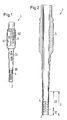
- ein Ausführungsbeispiel des erfindungsgemässen Hohlfräsers in perspektivischer Ansicht,
- Fig. 2
- das Ausführungsbeispiel des Hohlfräsers aus Fig. 1 im Längsschnitt,
- Fig. 3
- den Bereich des distalen Endes eines weiteren Ausführungsbeispiels des erfindungsgemässen Hohlfräsers
- Fig. 4
- ein Ausführungsbeispiel für die Ausgestaltung der stirnseitigen Zähne ("Bohrkrone") eines erfindungsgemässen Hohlfräsers.
- Fig. 1
- an embodiment of the hollow milling cutter according to the invention in a perspective view,
- Fig. 2
- the embodiment of the hollow milling cutter from FIG. 1 in longitudinal section,
- Fig. 3
- the region of the distal end of a further exemplary embodiment of the hollow milling cutter according to the invention
- Fig. 4
- an embodiment for the design of the front teeth ("drill bit") of a hollow milling cutter according to the invention.
Das Ausführungsbeispiel des erfindungsgemässen Hohlfräsers 1 gemäss
Fig. 1, welches in Fig. 2 im Längsschnitt (vergrössert) dargestellt ist, lässt
erkennen, dass der Hohlfräser 1 am distalen Ende stirnseitig angeordnete
Zähne 2 aufweist. In einem Bereich 3 nahe dem distalen Ende ist der
Hohlfräser 1 in seiner Wand mit diskreten Durchgangsbohrungen 4 versehen.
Dabei sind in Umfangsrichtung betrachtet mehrere Durchgangsbohrungen 4
vorgesehen, und in axialer Richtung betrachtet sind mehrere Lagen solcher
in Umfangsrichtung gleichmässig zueianander beabstandeter
Durchgangsbohrungen 4 vorgesehen. Diese Durchgangsbohrungen bewirken
eine Kühlung des Hohlfräsers 1 im Bereich 3 nahe dem distalen Ende, denn
dort kommt der Hohlfräser mit dem Gewebe in Kontakt.The embodiment of the hollow milling cutter 1 according to the invention
Fig. 1, which is shown in Fig. 2 in longitudinal section (enlarged)
recognize that the hollow milling cutter 1 is arranged on the end face at the distal end
Has
Im proximalen Bereich weist der Hohlfräser einen als Sechskant
ausgebildeten Bereich 5 auf, welcher in einem Futter (nicht dargestellt) eines
konventionellen Drehantriebs (chirurgische Bohrmaschine) aufgenommen
und eingespannt werden kann, sodass der Hohlfräser von diesem
Drehantrieb rotatorisch angetrieben werden kann.In the proximal area, the hollow milling cutter has a hexagon
trained
Wie man in Fig. 1 erkennt, können auf der Aussenwand des Hohlfräsers
verschiedene Markierungen (z.B. durch Laserbeschriftung) aufgebracht sein.
Im Bereich 3 können dies Markierungen 30 sein, welche dem Chirurgen bzw.
Orthopäden die Eindringtiefe des Hohlfräsers 1 anzeigen. Diese
Markierungen 30 können bis zum distalen Ende hin auf der Aussenwand
vorgesehen sein, also insbesondere auch in den Bereichen zwischen in
Umfangsrichtung benachbarten Durchgangsbohrungen 4. Aus Gründen der
besseren Übersichtlichkeit ist hierauf jedoch in Fig. 1 verzichtet worden.
Weiter proximal können z.B. Markierungen 31 vorgesehen sein, welche
Informationen über den Aussendurchmesser und den Innendurchmesser im
Bereich des distalen Endes des Hohlfräsers 1 geben (codiert oder unkodiert).
In dem Bereich 5, der als Sechskant ausgebildet ist, können dies z.B.
herstellerspezifische Informationen 50 sein (Herstellungsseriennummern,
Typennummern, etc.) oder auch Zertifizierungszeichen 51.As can be seen in Fig. 1, can on the outer wall of the hollow milling cutter
different markings (e.g. by laser inscription).
In area 3, these can be
Weiterhin kann der Innendurchmesser in dem Bereich 3 nahe dem distalen
Ende des Hohlfräsers 1 zunächst konstant sein (Bereich 32) und sich dann
leicht vergrössern (Bereich 33). Dies ist in Fig. 2 praktisch nicht zu erkennen,
weil die Vergrösserung des Innendurchmessers auch nicht beliebig sein
kann, da die Wandstärke des Hohlfräsers nicht beliebig klein sein kann,
immerhin müssen die für das Fräsen erforderlichen Kräfte auf die
Schnittfläche übertragen werden. Zweck der Vergrösserung des
Innendurchmessers im Bereich 33 ist, dass die Gewebesäule nur in dem
Bereich 32 noch Kontakt mit der Innenwand des Hohlfräsers 1 aufweist,
sodass der Hohlfräser nach Beendigung des Fräsvorgangs leichter
herausgenommen werden kann.Furthermore, the inner diameter in the area 3 near the distal
End of the hollow milling cutter 1 must first be constant (area 32) and then
enlarge slightly (area 33). This is practically not recognizable in FIG. 2,
because the enlargement of the inner diameter is also not arbitrary
can, since the wall thickness of the hollow milling cutter cannot be arbitrarily small,
after all, the forces required for milling must be on the
Cutting surface are transferred. Purpose of enlarging the
Inside diameter in area 33 is that the tissue column is only in the
Zu dem gleichen Zweck kann auch der Aussendurchmesser in dem Bereich 3 nahe dem distalen Ende des Hohlfräsers 1 zunächst konstant sein (Bereich 32) und sich dann leicht verringern. Auch dies ist in Fig. 2 praktisch nicht zu erkennen aus den bereits vorstehend genannten Gründen. Beide Massnahmen können kombiniert vorhanden sein oder nur eine der Massnahmen.For the same purpose, the outside diameter can also be in the region 3 near the distal end of the hollow milling cutter 1 must initially be constant (area 32) and then decrease slightly. This is also practically not possible in FIG. 2 recognize for the reasons already mentioned. Both Measures can be combined or only one of the Activities.
In Fig. 3 ist der Bereich 3a nahe dem distalen Ende eines weiteren Ausführungsbeispiels des erfindungsgemässen Hohlfräsers dargestellt. Man erkennt hier, dass die Mitel zum Kühlen eine in der Aussenwand des Hohlfräsers spiralförmig umlaufende Nut 34a umfassen (selbstverständlich können auch mehrere solcher spiralförmiger Nuten vorgesehen sein). Die Orientierung dieser Nut 34a ist entgegengesetzt zur Drehrichtung des Fräsers beim Abtragen von Gewebe. Wenn hier also der Fräser beim Rechtslauf Gewebe abträgt, so ist die Nut 34a in Linksdrehrichtung orientiert. In Fig. 3, area 3a is near the distal end of another Exemplary embodiment of the hollow milling cutter according to the invention is shown. Man recognizes here that the means for cooling one in the outer wall of the Hollow milling cutter spiral groove 34a include (of course can also be provided several such spiral grooves). The Orientation of this groove 34a is opposite to the direction of rotation of the Cutter while removing tissue. So if the router here If tissue rotates clockwise, groove 34a is oriented in the left-hand direction of rotation.
Dies hat zur Folge, dass beim Fräsen durch diese Nut 34a ein Kühlmittel, beispielsweise eine physiologische Salzlösung, zum distalen Ende des Fräsers geführt werden kann. Der Fräser kann daher im distalen Endbereich, wo er Kontakt zum Gewebe hat, gekühlt werden.The result of this is that a coolant, for example a physiological saline solution, to the distal end of the Milling cutter can be performed. The router can therefore in the distal end area, where it is in contact with the tissue.
In Fig. 4 ist schliesslich ein Ausführungsbeispiel der Ausgestaltung der
stirnseitigen Schneidezähne 2b dargestellt ("Bohrkrone"). Man erkennt hier,
dass sich die Zähne 2b von der Innenwand beginnend in Richtung auf das
distale Ende des Hohlfräsers hin nach aussen zuspitzen. Dadurch wird
erreicht, dass dann, wenn der Hohlfräser einmal nicht ganz genau orthogonal
auf das zu schneidende Gewebe aufgesetzt wird, dennoch nicht abgleiten
kann, weil die zugespitzten Zähne 2b besser in das Gewebe einhaken. Um
die Standzeit der Zähne 2b zu erhöhen, können die Zähne 2b an ihrer Spitze
mit einem sehr kleinen Radius abgerundet sein.4 is an embodiment of the embodiment of the
Als Materialien für solche Fräser kommt rostfreier Stahl in Frage, der ggf. mit einer Titannitrid-Beschichtung (TiN-Beschichtung) versehen sein kann. Der Stahl kann auch wärmebehandelt sein, insbesondere gehärtet und/oder vergütet. Der Fräser ist sterilisierbar und kann demzufolge nach Reinigung und anschliessendem Sterilisieren wiederverwendet werden.Stainless steel can be used as material for such milling cutters, if necessary with can be provided with a titanium nitride coating (TiN coating). The Steel can also be heat-treated, in particular hardened and / or hardened and tempered. The milling cutter can be sterilized and can therefore be cleaned and then re-sterilized.
Claims (10)
dadurch gekennzeichnet,
dass der Fräser Mittel (4,34a) zum Kühlen des nahe dem distalen Ende gelegenen Bereichs des Fräsers beim Abtragen von Gewebe aufweist.Hollow milling cutter (1) for creating essentially hollow cylindrical depressions in human or animal tissue, in particular for creating tissue columns, which are removed at a harvesting site, transported to a defect site and implanted there, which milling cutter has teeth (2) arranged on the end face at the distal end Showing removal of tissue,
characterized by
that the cutter has means (4,34a) for cooling the area of the cutter near the distal end as tissue is removed.
Priority Applications (1)
| Application Number | Priority Date | Filing Date | Title |
|---|---|---|---|
| EP99810790A EP0990421B1 (en) | 1998-09-29 | 1999-09-02 | Hollow mill for tissue |
Applications Claiming Priority (3)
| Application Number | Priority Date | Filing Date | Title |
|---|---|---|---|
| EP98810978 | 1998-09-29 | ||
| EP98810978 | 1998-09-29 | ||
| EP99810790A EP0990421B1 (en) | 1998-09-29 | 1999-09-02 | Hollow mill for tissue |
Publications (2)
| Publication Number | Publication Date |
|---|---|
| EP0990421A1 true EP0990421A1 (en) | 2000-04-05 |
| EP0990421B1 EP0990421B1 (en) | 2005-03-16 |
Family
ID=26152043
Family Applications (1)
| Application Number | Title | Priority Date | Filing Date |
|---|---|---|---|
| EP99810790A Expired - Lifetime EP0990421B1 (en) | 1998-09-29 | 1999-09-02 | Hollow mill for tissue |
Country Status (1)
| Country | Link |
|---|---|
| EP (1) | EP0990421B1 (en) |
Cited By (2)
| Publication number | Priority date | Publication date | Assignee | Title |
|---|---|---|---|---|
| FR2902310A1 (en) * | 2006-06-14 | 2007-12-21 | Jean Claude Yeung | TREPAN FOR THE REMOVAL OF A BONE CARROT, PROVIDED WITH A GUIDING DEVICE WITHIN THE BONE, REMOVING THE CARROT OUT OF THE TREPAN, AND IRRIGATION DURING BONE SAMPLING. |
| CN102038537A (en) * | 2011-02-10 | 2011-05-04 | 孙涛 | Distal automatic cutting bone core extraction device |
Citations (8)
| Publication number | Priority date | Publication date | Assignee | Title |
|---|---|---|---|---|
| GB2040741A (en) * | 1979-01-31 | 1980-09-03 | Jowsey A C | Annular cutting tool |
| JPS6090547A (en) * | 1983-10-25 | 1985-05-21 | 株式会社東理社 | Hard tissue cooling and cutting apparatus |
| US4538944A (en) * | 1981-09-21 | 1985-09-03 | Hougen Everett D | Annular cutter |
| DE3408313A1 (en) * | 1984-03-07 | 1985-09-19 | Hager & Meisinger GmbH, 4000 Düsseldorf | Dental rotating tool |
| EP0574736A1 (en) * | 1992-06-06 | 1993-12-22 | MERCK PATENT GmbH | Drilling and abrasion tool for bony materials |
| EP0611624A1 (en) * | 1993-02-15 | 1994-08-24 | Siemens Aktiengesellschaft | Rotary tool for high speed drive |
| US5632747A (en) * | 1995-03-15 | 1997-05-27 | Osteotech, Inc. | Bone dowel cutter |
| EP0824893A2 (en) * | 1996-08-16 | 1998-02-25 | Arthrex Inc | Apparatus for osteochondral autograft transplantation |
-
1999
- 1999-09-02 EP EP99810790A patent/EP0990421B1/en not_active Expired - Lifetime
Patent Citations (8)
| Publication number | Priority date | Publication date | Assignee | Title |
|---|---|---|---|---|
| GB2040741A (en) * | 1979-01-31 | 1980-09-03 | Jowsey A C | Annular cutting tool |
| US4538944A (en) * | 1981-09-21 | 1985-09-03 | Hougen Everett D | Annular cutter |
| JPS6090547A (en) * | 1983-10-25 | 1985-05-21 | 株式会社東理社 | Hard tissue cooling and cutting apparatus |
| DE3408313A1 (en) * | 1984-03-07 | 1985-09-19 | Hager & Meisinger GmbH, 4000 Düsseldorf | Dental rotating tool |
| EP0574736A1 (en) * | 1992-06-06 | 1993-12-22 | MERCK PATENT GmbH | Drilling and abrasion tool for bony materials |
| EP0611624A1 (en) * | 1993-02-15 | 1994-08-24 | Siemens Aktiengesellschaft | Rotary tool for high speed drive |
| US5632747A (en) * | 1995-03-15 | 1997-05-27 | Osteotech, Inc. | Bone dowel cutter |
| EP0824893A2 (en) * | 1996-08-16 | 1998-02-25 | Arthrex Inc | Apparatus for osteochondral autograft transplantation |
Cited By (4)
| Publication number | Priority date | Publication date | Assignee | Title |
|---|---|---|---|---|
| FR2902310A1 (en) * | 2006-06-14 | 2007-12-21 | Jean Claude Yeung | TREPAN FOR THE REMOVAL OF A BONE CARROT, PROVIDED WITH A GUIDING DEVICE WITHIN THE BONE, REMOVING THE CARROT OUT OF THE TREPAN, AND IRRIGATION DURING BONE SAMPLING. |
| WO2007144502A2 (en) * | 2006-06-14 | 2007-12-21 | Jean-Claude Yeung | Trephine designed for removal of a bone core and equipped with a device guiding it inside the bone and combining a drill bit and a tubular cutting tool |
| WO2007144502A3 (en) * | 2006-06-14 | 2008-02-14 | Jean-Claude Yeung | Trephine designed for removal of a bone core and equipped with a device guiding it inside the bone and combining a drill bit and a tubular cutting tool |
| CN102038537A (en) * | 2011-02-10 | 2011-05-04 | 孙涛 | Distal automatic cutting bone core extraction device |
Also Published As
| Publication number | Publication date |
|---|---|
| EP0990421B1 (en) | 2005-03-16 |
Similar Documents
| Publication | Publication Date | Title |
|---|---|---|
| EP1779791B1 (en) | Facet joint milling tool | |
| EP0275375B1 (en) | Rasp-like extracting instrument | |
| DE602004008024T2 (en) | Devices for minimally invasive milling of bones | |
| EP0928164B1 (en) | Bone cutter | |
| DE60015636T2 (en) | Compression bone screw and auxiliary instruments for their attachment | |
| DE102008029920B4 (en) | Trepan | |
| EP0693274A1 (en) | Implant for maintaining the normal spacing between two vertebrae | |
| DE202011111061U1 (en) | Orthopedic milling device for bone preparation, in particular joint preparation | |
| DE19509317A1 (en) | Spinal column implant for mounting between vertebrae | |
| DE3143591A1 (en) | Dental spiral drill | |
| EP0118778A1 (en) | Fixing nail | |
| WO2011131357A2 (en) | Surgical tool, in particular for drilling bone for inserting a dental implant | |
| DE102005017285B4 (en) | Implant drill | |
| DE3433570A1 (en) | Circulating tool for surgical, especially dental surgical, purposes and device for supplying the instrument with a coolant | |
| WO2009135514A1 (en) | Surgical tool, especially for machining bones for insertion of a dental implant | |
| DE1930354C3 (en) | Fixation device | |
| EP2666418B1 (en) | Surgical milling tool | |
| EP0986989A1 (en) | Flexible shaft and surgical instrument comprising such a shaft | |
| DE10038480C2 (en) | Milling cutter for tissue | |
| EP0990421B1 (en) | Hollow mill for tissue | |
| EP0279075A2 (en) | Dental drill | |
| EP1994892A1 (en) | Instrument set for minimally invasive preparation of a bone nailing procedure | |
| DE202010005376U1 (en) | Surgical instrument and surgical instruments | |
| EP1030620B1 (en) | Dental instrument | |
| EP3294156B1 (en) | Surgical hand-held instrument and a protection device |
Legal Events
| Date | Code | Title | Description |
|---|---|---|---|
| PUAI | Public reference made under article 153(3) epc to a published international application that has entered the european phase |
Free format text: ORIGINAL CODE: 0009012 |
|
| AK | Designated contracting states |
Kind code of ref document: A1 Designated state(s): AT CH DE FR GB IT LI |
|
| AX | Request for extension of the european patent |
Free format text: AL;LT;LV;MK;RO;SI |
|
| 17P | Request for examination filed |
Effective date: 20000908 |
|
| AKX | Designation fees paid |
Free format text: AT CH DE FR GB IT LI |
|
| 17Q | First examination report despatched |
Effective date: 20030107 |
|
| GRAP | Despatch of communication of intention to grant a patent |
Free format text: ORIGINAL CODE: EPIDOSNIGR1 |
|
| RAP1 | Party data changed (applicant data changed or rights of an application transferred) |
Owner name: ZIMMER GMBH |
|
| GRAS | Grant fee paid |
Free format text: ORIGINAL CODE: EPIDOSNIGR3 |
|
| GRAA | (expected) grant |
Free format text: ORIGINAL CODE: 0009210 |
|
| AK | Designated contracting states |
Kind code of ref document: B1 Designated state(s): AT CH DE FR GB IT LI |
|
| REG | Reference to a national code |
Ref country code: GB Ref legal event code: FG4D Free format text: NOT ENGLISH |
|
| REG | Reference to a national code |
Ref country code: CH Ref legal event code: NV Representative=s name: DR. GRAF & PARTNER INTELLECTUAL PROPERTY Ref country code: CH Ref legal event code: EP |
|
| REF | Corresponds to: |
Ref document number: 59911756 Country of ref document: DE Date of ref document: 20050421 Kind code of ref document: P |
|
| GBT | Gb: translation of ep patent filed (gb section 77(6)(a)/1977) |
Effective date: 20050517 |
|
| PLBE | No opposition filed within time limit |
Free format text: ORIGINAL CODE: 0009261 |
|
| STAA | Information on the status of an ep patent application or granted ep patent |
Free format text: STATUS: NO OPPOSITION FILED WITHIN TIME LIMIT |
|
| ET | Fr: translation filed | ||
| 26N | No opposition filed |
Effective date: 20051219 |
|
| PGFP | Annual fee paid to national office [announced via postgrant information from national office to epo] |
Ref country code: AT Payment date: 20080820 Year of fee payment: 10 |
|
| REG | Reference to a national code |
Ref country code: CH Ref legal event code: PFA Owner name: ZIMMER GMBH Free format text: ZIMMER GMBH#SULZER ALLEE 8#8404 WINTERTHUR (CH) -TRANSFER TO- ZIMMER GMBH#SULZER ALLEE 8#8404 WINTERTHUR (CH) |
|
| PG25 | Lapsed in a contracting state [announced via postgrant information from national office to epo] |
Ref country code: AT Free format text: LAPSE BECAUSE OF NON-PAYMENT OF DUE FEES Effective date: 20090902 |
|
| PGFP | Annual fee paid to national office [announced via postgrant information from national office to epo] |
Ref country code: DE Payment date: 20100930 Year of fee payment: 12 |
|
| PGFP | Annual fee paid to national office [announced via postgrant information from national office to epo] |
Ref country code: CH Payment date: 20110729 Year of fee payment: 13 |
|
| PGFP | Annual fee paid to national office [announced via postgrant information from national office to epo] |
Ref country code: GB Payment date: 20110826 Year of fee payment: 13 Ref country code: FR Payment date: 20110901 Year of fee payment: 13 |
|
| PGFP | Annual fee paid to national office [announced via postgrant information from national office to epo] |
Ref country code: IT Payment date: 20110922 Year of fee payment: 13 |
|
| REG | Reference to a national code |
Ref country code: CH Ref legal event code: PL |
|
| GBPC | Gb: european patent ceased through non-payment of renewal fee |
Effective date: 20120902 |
|
| REG | Reference to a national code |
Ref country code: FR Ref legal event code: ST Effective date: 20130531 |
|
| REG | Reference to a national code |
Ref country code: DE Ref legal event code: R119 Ref document number: 59911756 Country of ref document: DE Effective date: 20130403 |
|
| PG25 | Lapsed in a contracting state [announced via postgrant information from national office to epo] |
Ref country code: LI Free format text: LAPSE BECAUSE OF NON-PAYMENT OF DUE FEES Effective date: 20120930 Ref country code: GB Free format text: LAPSE BECAUSE OF NON-PAYMENT OF DUE FEES Effective date: 20120902 Ref country code: CH Free format text: LAPSE BECAUSE OF NON-PAYMENT OF DUE FEES Effective date: 20120930 Ref country code: DE Free format text: LAPSE BECAUSE OF NON-PAYMENT OF DUE FEES Effective date: 20130403 |
|
| PG25 | Lapsed in a contracting state [announced via postgrant information from national office to epo] |
Ref country code: IT Free format text: LAPSE BECAUSE OF NON-PAYMENT OF DUE FEES Effective date: 20120902 Ref country code: FR Free format text: LAPSE BECAUSE OF NON-PAYMENT OF DUE FEES Effective date: 20121001 |