EP0990777B1 - Regeneration system for an exhaust gas cleaning device - Google Patents
Regeneration system for an exhaust gas cleaning device Download PDFInfo
- Publication number
- EP0990777B1 EP0990777B1 EP99307673A EP99307673A EP0990777B1 EP 0990777 B1 EP0990777 B1 EP 0990777B1 EP 99307673 A EP99307673 A EP 99307673A EP 99307673 A EP99307673 A EP 99307673A EP 0990777 B1 EP0990777 B1 EP 0990777B1
- Authority
- EP
- European Patent Office
- Prior art keywords
- filter
- exhaust gas
- regeneration
- glow plug
- pressure loss
- Prior art date
- Legal status (The legal status is an assumption and is not a legal conclusion. Google has not performed a legal analysis and makes no representation as to the accuracy of the status listed.)
- Expired - Lifetime
Links
Images


Classifications
-
- B—PERFORMING OPERATIONS; TRANSPORTING
- B01—PHYSICAL OR CHEMICAL PROCESSES OR APPARATUS IN GENERAL
- B01D—SEPARATION
- B01D53/00—Separation of gases or vapours; Recovering vapours of volatile solvents from gases; Chemical or biological purification of waste gases, e.g. engine exhaust gases, smoke, fumes, flue gases, aerosols
- B01D53/34—Chemical or biological purification of waste gases
- B01D53/92—Chemical or biological purification of waste gases of engine exhaust gases
- B01D53/94—Chemical or biological purification of waste gases of engine exhaust gases by catalytic processes
- B01D53/9445—Simultaneously removing carbon monoxide, hydrocarbons or nitrogen oxides making use of three-way catalysts [TWC] or four-way-catalysts [FWC]
- B01D53/9454—Simultaneously removing carbon monoxide, hydrocarbons or nitrogen oxides making use of three-way catalysts [TWC] or four-way-catalysts [FWC] characterised by a specific device
-
- B—PERFORMING OPERATIONS; TRANSPORTING
- B01—PHYSICAL OR CHEMICAL PROCESSES OR APPARATUS IN GENERAL
- B01D—SEPARATION
- B01D53/00—Separation of gases or vapours; Recovering vapours of volatile solvents from gases; Chemical or biological purification of waste gases, e.g. engine exhaust gases, smoke, fumes, flue gases, aerosols
- B01D53/34—Chemical or biological purification of waste gases
- B01D53/96—Regeneration, reactivation or recycling of reactants
-
- F—MECHANICAL ENGINEERING; LIGHTING; HEATING; WEAPONS; BLASTING
- F01—MACHINES OR ENGINES IN GENERAL; ENGINE PLANTS IN GENERAL; STEAM ENGINES
- F01N—GAS-FLOW SILENCERS OR EXHAUST APPARATUS FOR MACHINES OR ENGINES IN GENERAL; GAS-FLOW SILENCERS OR EXHAUST APPARATUS FOR INTERNAL COMBUSTION ENGINES
- F01N3/00—Exhaust or silencing apparatus having means for purifying, rendering innocuous, or otherwise treating exhaust
- F01N3/02—Exhaust or silencing apparatus having means for purifying, rendering innocuous, or otherwise treating exhaust for cooling, or for removing solid constituents of, exhaust
- F01N3/021—Exhaust or silencing apparatus having means for purifying, rendering innocuous, or otherwise treating exhaust for cooling, or for removing solid constituents of, exhaust by means of filters
- F01N3/023—Exhaust or silencing apparatus having means for purifying, rendering innocuous, or otherwise treating exhaust for cooling, or for removing solid constituents of, exhaust by means of filters using means for regenerating the filters, e.g. by burning trapped particles
- F01N3/027—Exhaust or silencing apparatus having means for purifying, rendering innocuous, or otherwise treating exhaust for cooling, or for removing solid constituents of, exhaust by means of filters using means for regenerating the filters, e.g. by burning trapped particles using electric or magnetic heating means
-
- F—MECHANICAL ENGINEERING; LIGHTING; HEATING; WEAPONS; BLASTING
- F01—MACHINES OR ENGINES IN GENERAL; ENGINE PLANTS IN GENERAL; STEAM ENGINES
- F01N—GAS-FLOW SILENCERS OR EXHAUST APPARATUS FOR MACHINES OR ENGINES IN GENERAL; GAS-FLOW SILENCERS OR EXHAUST APPARATUS FOR INTERNAL COMBUSTION ENGINES
- F01N3/00—Exhaust or silencing apparatus having means for purifying, rendering innocuous, or otherwise treating exhaust
- F01N3/02—Exhaust or silencing apparatus having means for purifying, rendering innocuous, or otherwise treating exhaust for cooling, or for removing solid constituents of, exhaust
- F01N3/021—Exhaust or silencing apparatus having means for purifying, rendering innocuous, or otherwise treating exhaust for cooling, or for removing solid constituents of, exhaust by means of filters
- F01N3/031—Exhaust or silencing apparatus having means for purifying, rendering innocuous, or otherwise treating exhaust for cooling, or for removing solid constituents of, exhaust by means of filters having means for by-passing filters, e.g. when clogged or during cold engine start
- F01N3/032—Exhaust or silencing apparatus having means for purifying, rendering innocuous, or otherwise treating exhaust for cooling, or for removing solid constituents of, exhaust by means of filters having means for by-passing filters, e.g. when clogged or during cold engine start during filter regeneration only
-
- F—MECHANICAL ENGINEERING; LIGHTING; HEATING; WEAPONS; BLASTING
- F01—MACHINES OR ENGINES IN GENERAL; ENGINE PLANTS IN GENERAL; STEAM ENGINES
- F01N—GAS-FLOW SILENCERS OR EXHAUST APPARATUS FOR MACHINES OR ENGINES IN GENERAL; GAS-FLOW SILENCERS OR EXHAUST APPARATUS FOR INTERNAL COMBUSTION ENGINES
- F01N3/00—Exhaust or silencing apparatus having means for purifying, rendering innocuous, or otherwise treating exhaust
- F01N3/02—Exhaust or silencing apparatus having means for purifying, rendering innocuous, or otherwise treating exhaust for cooling, or for removing solid constituents of, exhaust
- F01N3/021—Exhaust or silencing apparatus having means for purifying, rendering innocuous, or otherwise treating exhaust for cooling, or for removing solid constituents of, exhaust by means of filters
- F01N3/033—Exhaust or silencing apparatus having means for purifying, rendering innocuous, or otherwise treating exhaust for cooling, or for removing solid constituents of, exhaust by means of filters in combination with other devices
- F01N3/035—Exhaust or silencing apparatus having means for purifying, rendering innocuous, or otherwise treating exhaust for cooling, or for removing solid constituents of, exhaust by means of filters in combination with other devices with catalytic reactors, e.g. catalysed diesel particulate filters
-
- F—MECHANICAL ENGINEERING; LIGHTING; HEATING; WEAPONS; BLASTING
- F01—MACHINES OR ENGINES IN GENERAL; ENGINE PLANTS IN GENERAL; STEAM ENGINES
- F01N—GAS-FLOW SILENCERS OR EXHAUST APPARATUS FOR MACHINES OR ENGINES IN GENERAL; GAS-FLOW SILENCERS OR EXHAUST APPARATUS FOR INTERNAL COMBUSTION ENGINES
- F01N2240/00—Combination or association of two or more different exhaust treating devices, or of at least one such device with an auxiliary device, not covered by indexing codes F01N2230/00 or F01N2250/00, one of the devices being
- F01N2240/16—Combination or association of two or more different exhaust treating devices, or of at least one such device with an auxiliary device, not covered by indexing codes F01N2230/00 or F01N2250/00, one of the devices being an electric heater, i.e. a resistance heater
-
- F—MECHANICAL ENGINEERING; LIGHTING; HEATING; WEAPONS; BLASTING
- F01—MACHINES OR ENGINES IN GENERAL; ENGINE PLANTS IN GENERAL; STEAM ENGINES
- F01N—GAS-FLOW SILENCERS OR EXHAUST APPARATUS FOR MACHINES OR ENGINES IN GENERAL; GAS-FLOW SILENCERS OR EXHAUST APPARATUS FOR INTERNAL COMBUSTION ENGINES
- F01N2330/00—Structure of catalyst support or particle filter
- F01N2330/14—Sintered material
-
- F—MECHANICAL ENGINEERING; LIGHTING; HEATING; WEAPONS; BLASTING
- F01—MACHINES OR ENGINES IN GENERAL; ENGINE PLANTS IN GENERAL; STEAM ENGINES
- F01N—GAS-FLOW SILENCERS OR EXHAUST APPARATUS FOR MACHINES OR ENGINES IN GENERAL; GAS-FLOW SILENCERS OR EXHAUST APPARATUS FOR INTERNAL COMBUSTION ENGINES
- F01N2510/00—Surface coverings
- F01N2510/06—Surface coverings for exhaust purification, e.g. catalytic reaction
-
- Y—GENERAL TAGGING OF NEW TECHNOLOGICAL DEVELOPMENTS; GENERAL TAGGING OF CROSS-SECTIONAL TECHNOLOGIES SPANNING OVER SEVERAL SECTIONS OF THE IPC; TECHNICAL SUBJECTS COVERED BY FORMER USPC CROSS-REFERENCE ART COLLECTIONS [XRACs] AND DIGESTS
- Y02—TECHNOLOGIES OR APPLICATIONS FOR MITIGATION OR ADAPTATION AGAINST CLIMATE CHANGE
- Y02T—CLIMATE CHANGE MITIGATION TECHNOLOGIES RELATED TO TRANSPORTATION
- Y02T10/00—Road transport of goods or passengers
- Y02T10/10—Internal combustion engine [ICE] based vehicles
- Y02T10/12—Improving ICE efficiencies
-
- Y—GENERAL TAGGING OF NEW TECHNOLOGICAL DEVELOPMENTS; GENERAL TAGGING OF CROSS-SECTIONAL TECHNOLOGIES SPANNING OVER SEVERAL SECTIONS OF THE IPC; TECHNICAL SUBJECTS COVERED BY FORMER USPC CROSS-REFERENCE ART COLLECTIONS [XRACs] AND DIGESTS
- Y10—TECHNICAL SUBJECTS COVERED BY FORMER USPC
- Y10S—TECHNICAL SUBJECTS COVERED BY FORMER USPC CROSS-REFERENCE ART COLLECTIONS [XRACs] AND DIGESTS
- Y10S55/00—Gas separation
- Y10S55/10—Residue burned
-
- Y—GENERAL TAGGING OF NEW TECHNOLOGICAL DEVELOPMENTS; GENERAL TAGGING OF CROSS-SECTIONAL TECHNOLOGIES SPANNING OVER SEVERAL SECTIONS OF THE IPC; TECHNICAL SUBJECTS COVERED BY FORMER USPC CROSS-REFERENCE ART COLLECTIONS [XRACs] AND DIGESTS
- Y10—TECHNICAL SUBJECTS COVERED BY FORMER USPC
- Y10S—TECHNICAL SUBJECTS COVERED BY FORMER USPC CROSS-REFERENCE ART COLLECTIONS [XRACs] AND DIGESTS
- Y10S55/00—Gas separation
- Y10S55/30—Exhaust treatment
Definitions
- This invention relates to a regeneration system for an exhaust gas cleaning device, and more particularly to a regeneration system comprising an exhaust gas cleaning device disposed in an exhaust emission path of an internal combustion engine and provided with an exhaust gas cleaning honeycomb filter for catching particulates included in the exhaust gas and a heating means for the exhaust gas cleaning honeycomb filter when a fuel containing a fuel additive for mitigating particulates included in the exhaust gas is used as a fuel for the internal combustion engine.
- particulates e.g. soot or unburned portion of fuel
- the discharge amount of particulates becomes large in a diesel engine using a gas oil as a fuel or a direct-injection type gasoline engine recently coming into wide use. Therefore, it is well-known to remove the particulates by an exhaust gas cleaning device disposed in an exhaust emission path of the internal combustion engine and provided with an exhaust gas cleaning honeycomb filter.
- a cordierite filter 32 of a honeycomb structure as shown by a diagrammatically section view in Fig. 1.
- a conventional cordierite filter 32 are included a plurality of exhaust gas flowing channels 33 extending in parallel to a longitudinal direction thereof, wherein these channels 33 are alternately plugged at either upstream side or downstream side for the exhaust gas of their ends with plugging members 33a to form a checker pattern.
- an exhaust gas Gin emitted from a diesel engine flows into the cordierite filter 32 through the exhaust emission path 11, at where particulates included in the exhaust gas are filtered off on surfaces of cell walls constituting the exhaust gas flowing channels 33. Then, the cleaned exhaust gas Gout passed through cordierite filter 32 again passes through the exhaust emission path 11 and is discharged out to the outside of the vehicle.
- pressure loss ⁇ P is produced when the exhaust gas Gin passes through the filter 32.
- the pressure loss ⁇ P is represented by the following equation (1).
- ⁇ P ⁇ P1 + ⁇ P2 + ⁇ P3 + ⁇ P4
- ⁇ P1 is a resistance produced due to the narrowing of an opening portion in the exhaust gas flowing channel 33 when the exhaust gas flows into the channel 33 through the exhaust emission path 11;
- the resistances ⁇ P1, ⁇ P2, ⁇ P3 are dependent upon a cell structure constituting the filter 32, respectively and are a constant value ⁇ Pi not depended upon the lapse of time coming into problem in the deposition of the particulates and the like (hereinafter " ⁇ P1 + ⁇ P2 + ⁇ P3" is called as "initial pressure loss").
- ⁇ P1 + ⁇ P2 + ⁇ P3 is called as "initial pressure loss”
- a greater part of the pressure loss ⁇ P is determined by the resistance ⁇ P4 produced when the exhaust gas passes through the particulates deposited on the cell walls.
- the resistance ⁇ P4 is usually 2-3 times the initial pressure loss ⁇ Pi at a deposited state of the particulates.
- Fig. 2 is shown a relation among cell structure, typical dimensions, geometrical surface area and opening ratio in the filter.
- the cell wall thickness dc is shown by unit of mm in Fig. 2.
- the pressure loss ⁇ P produced in the checkered honeycomb filter for cleaning the exhaust gas is small as the cell number Nc and geometrical surface area fs in the filter become large.
- the opening ratio ⁇ (%) is a ratio of total opening area of the exhaust gas flowing channels occupied in the sectional area of the filter.
- a limit not creating cracks is large as the opening ratio ⁇ becomes small.
- a mechanical strength of the filter i.e. bending strength S* of the filter is approximately equal to product of strength S of a filter made of porous material and relative density ⁇ * as mentioned below.
- the regeneration of the filter is carried out by burning the particulates according to the following reaction equation (4): C + O 2 ⁇ CO 2 + Q (heat quantity) so that the strength of the filter against the thermal stress becomes important.
- C + O 2 ⁇ CO 2 + Q heat quantity
- the filter is made from a ceramic material, brittle rupture is caused by thermal stress to create cracks.
- Such a cracking phenomenon is apt to be created as heat quantity produced in the regeneration or the amount of the particulates deposited to be burnt becomes large.
- the unburned portion of fuel constituting the particulate is an organic compound, so that it is burned by heating the filter.
- a crack limit preventing the occurrence of the cracking phenomenon is proportional to the opening ratio ⁇ and is closely related to the thickness dc of the cell wall as seen from Fig. 2. If the opening ratio ⁇ is same, as the thickness dc of the cell wall becomes thick, the crack limit is high.
- the exhaust gas cleaning filter having good properties is preferably made of a material having a large crack limit, an excellent strength against thermal stress and a small pressure loss.
- fuel previously including a fuel additive, or a device dropwise adding a fuel additive to a fuel is developed for controlling the amount of the particulate produced in the exhaust gas and the use thereof is increasing.
- a fuel additive has an effect of preventing the formation of soot in the burning of the fuel.
- the formation of the particulate can not completely be controlled even by using such a fuel additive and hence the particulate is formed in the exhaust gas. Therefore, it is indispensable to use the exhaust gas cleaning filter.
- the cordierite filter is generally adopted as a checkered honeycomb filter for cleaning the exhaust gas as previously mentioned.
- the amount of the particulate to be treated in one regeneration of the cordierite filter has a limit because the maximum service temperature in the filter is low.
- a large pressure loss is caused in the filter due to the deposition of the particulate, so that the combustion efficiency of the internal combustion engine lowers to degrade the fuel consumption.
- Fig. 3 are shown experimental data illustrating a relation among pressure loss ⁇ P (mmAq) and temperature T (°C) and time t (min) in the conventional checkered honeycomb cordierite filter for cleaning the exhaust gas.
- symbol Pn is a case of burning a fuel containing no fuel additive, wherein the pressure loss ⁇ P in the filter continuously rises in proportion to the deposition of the particulate even when the temperature Tn rises with the increase of the engine revolution number (engine loading).
- the beginning temperature of burning the particulates in case of using the fuel containing no fuel additive is generally about 630°C.
- the cell structure Cs of the cordierite filter In order to reduce the pressure loss produced in the cordierite filter, therefore, it is considered to finely set the cell structure Cs of the cordierite filter with reference to Fig. 2. For example, it is considered that the cell number Nc (cpi) is set to a large value, while the thickness dc of the cell wall is set to a small value.
- the cordierite honeycomb filter having the cell number Nc of more than 100 cpi, but when such a filter is used as a checkered honeycomb filter capable of efficiently burning the particulate, the cracking is caused in view of the crack limit of cordierite itself, so that the cell number Nc (cpi) can not be made more than 100 when the checkered honeycomb filter for cleaning the exhaust gas is made of cordierite.
- DE 4021033A1 discloses a prior art exhaust cleaner for an internal combustion engine of a motor vehicle.
- the cleaner is provided with porous silicon-carbide filter in thermally insulating mounting for burning off carbon deposits.
- the thermal conductivity of the silicon carbide is used to ensure rapid burn of the carbon when the integral electric heating element is powered.
- the heating can be provided by a direct electric element, microwave heating or hot gas heating.
- the invention provides a regeneration system for an exhaust gas cleaning device disposed in an exhaust emission path of an internal combustion engine comprising an exhaust gas cleaning honeycomb filter for collecting particulates included in the exhaust gas and a heating means for the exhaust gas cleaning honeycomb filter, said filter is a checked honeycomb filter made of a porous silicon carbide sintered body and having a cell structure wherein the cell number per square inch is not less than 100 cells and wherein the thickness of a cell wall is not more than 0.43 mm, and said heating means is selected from a heater and a glow plug and disposed in front of an upstream end face of the filter to heat the exhaust gas characterised in that said internal combustion engine uses a gas oil containing a fuel additive for controlling the amount of particulates produced in the exhaust gas and to obtain a particulate burning temperature of at least 150°C sufficient for attaining a filter regeneration ratio of not less than 80%.
- the glow plug is a ceramic glow plug.
- the filter has a total volume corresponding to 1/4-2 times an engine swept volume of the internal combustion engine.
- the exhaust gas cleaning honeycomb filter is a checkered SiC honeycomb filter made of a porous silicon carbide sintered body, so that it is high in the crack limit and excellent in the strength against thermal stress as compared with those of the conventional cordierite filter and hence the durability of the filter is high.
- the heater or the glow plug as the heating means for the exhaust gas cleaning filter is arranged ahead the filter in the exhaust gas cleaning device, so that even if the temperature of the exhaust gas is not raised to a level required for burning the particulate during the running of the vehicle on urban area at a low speed or the like, the particulate can be burned by heating the filter through such a heating means, and hence the regeneration of the filter can completely be attained.
- the space in the exhaust gas cleaning device can be saved and power consumption can be decreased as compared with those in the use of the heater.
- the glow plug there are a metal glow plug and a ceramic glow plug.
- the use of the ceramic glow plug is favorable because the time reaching to a given temperature by heating is faster than that of the metal glow plug and a saturated temperature can be made higher.
- the ceramic glow plug is small in the power consumption as compared with the metal glow plug and is high in the durability. Therefore, the more efficient regeneration of the filter can be attained by the use of the ceramic glow plug as compared with the use of the heater or the metal glow plug.
- the total volume of the exhaust gas cleaning filter is set to 1/4-2 times the engine swept volume of the internal combustion engine because the total volume is dependent upon the engine swept volume.
- the total volume of the filter is less than 1/4 times the engine swept volume, the sufficient filtering area can not be ensured and the pressure loss becomes larger to bring about the remarkable degradation of the fuel consumption, while when it exceeds 2.0 times, it is difficult to arrange the exhaust gas cleaning device inclusive of the filter in the exhaust emission path but also the thermal capacity becomes larger to delay reaction to the temperature of the exhaust gas to thereby lose a chance of obtaining a regeneratable temperature of the filter for burning the particulate.
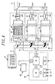
- FIG. 4 a first embodiment of the regeneration system for the exhaust gas cleaning device for use in a diesel engine according to the invention.
- This system is a system for the regeneration of an exhaust gas cleaning device 20 cleaning the exhaust gas discharged from a diesel engine 10 using a gas oil containing a fuel additive, and comprises three regeneration units 12-1, 12-2, 12-3 disposed on a way of an exhaust emission path 11 from the engine 10 in a branched form.
- Each of these units comprises an exhaust gas cleaning device 20 provided with an exhaust gas cleaning filter 22 made of a porous silicon carbide (SiC) sintered body and carried with a catalyst for exhaust gas purification, a heating means 24 disposed ahead an end face of the SiC filter 22 at an upstream side thereof for heating the SiC filter 22, and a flow control valve 26 disposed at a downstream side of the SiC filter 22.
- the regeneration system comprises a control unit 40 for controlling power supplied to the heating means 24 and the flow control valve 26.
- the control unit 40 is connected to a battery 28 mounted on a vehicle (not shown) and controls the heating means 24 and the flow control valve 26 independently.
- the control unit 40 comprises an input part 42 inputted with measured values of engine revolution number Ne (rpm) and pressure loss ⁇ P (mmAq) and temperature T in an exhaust gas cleaning device 20, CPU (central processing unit) 44 processing output signals from the input part 42 for controlling actions of the heating means 24 and the flow control valve 26, a heater controlling unit 46 operating the heating means 24 based on the processed result in CPU 44, and an output part 48 operating the flow control valve 26 to a throttle position (see a position of a valve body 26a in the regeneration unit 12-1 of Fig. 4).
- CPU central processing unit
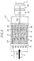
- the heating means 24 is a spiral-shaped resistance heating heater disposed apart from the upstream end face of the SiC filter 22 at a given distance.
- the heater is not restricted to the above spiral form and may take any forms as long as the exhaust gas from the engine 10 is passed in the arrangement ahead the SiC filter 22.
- the kind of the heater is not particularly restricted, but a sheathed heater and the like may be used.
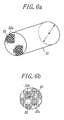
- the honeycomb filter 22 for cleaning the exhaust gas is made of a porous silicon carbide (SiC) sintered body of a honeycomb structure.
- SiC honeycomb filter 22 are formed a plurality of exhaust gas flowing channels 23 extending in parallel to a longitudinal direction thereof, wherein these channels 23 are alternately plugged at either inlet side or outlet side for the exhaust gas of their ends with plugging members 23a to form a checker pattern.
- the exhaust gas cleaning honeycomb filter 22 made of the porous silicon carbide sintered body is a checkered SiC honeycomb filter having a given cell wall thickness dc at the upstream and downstream end faces thereof (see Fig. 6).
- the checkered SiC honeycomb filter 22 is closely held in a casing of the exhaust gas cleaning device 20 through a heat insulating material 23b arranged on the outer periphery of the filter.
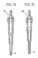
- a second embodiment of the regeneration system for the exhaust gas cleaning device for use in a diesel engine according to the invention has the same structure as in the first embodiment except that a glow plug 34 is used instead of the heater as the heating means 24 as shown in Fig. 7.
- a glow plug 34 there are two plugs as shown in Figs. 7a and 7b.
- the plug shown in Fig. 7a is a ceramic glow plug 34a using an electrically conductive ceramic 35 attached to a top of the plug as a heating portion, wherein heat is generated by flowing current through the electrically conductive ceramic 35.
- the plug shown in Fig. 7b is a metal glow plug 34b using a heating coil 36 attached to the top of the plug as a heating part, wherein heat is generated by flowing current through the heating coil 36.
- Fig. 8 is shown a comparison in properties between the ceramic glow plug 34a and the metal glow plug 34b.
- the time reaching to 800°C by heating is a surface temperature rising rate of the heating portion at the top of the plug
- the saturated temperature is a temperature when the surface temperature of the glow plug arrives at a saturated state or a temperature capable of conducting the burning at a stable state.
- the time reaching to 800°C by heating is 3.5 seconds in the ceramic glow plug 34a and 5.5 seconds in the metal glow plug 34b.
- the saturated temperature is 1100°C in the ceramic glow plug 34a, while that in the metal glow plug 34b is as low as 900°C.
- the power consumption per one plug is 36 W in the ceramic glow plug 34a, while that in the metal glow plug 34b is required to be 55 W.
- service life of the ceramic glow plug 34a converted to a running distance is not less than 200,000 km, while that of the metal glow plug 34b is about 100,000 km.
- the ceramic glow plug 34a when the ceramic glow plug 34a is compared with the metal glow plug 34b, it is effective to use the ceramic glow plug 34a as a glow plug used as a heating means for the filter.
- the particulate included in the exhaust gas is filtered off on the surfaces of the exhaust gas flowing channels 23.
- the exhaust gas Gout cleaned through the checkered honeycomb SiC filter 22 is again flowed into the exhaust emission path 11 and discharged out therefrom to the outside of the vehicle.
- the particulate included in the exhaust gas is gradually deposited on the inner wall surfaces of the channels 23. Therefore, it is required to regenerate the exhaust gas cleaning device by heating the honeycomb SiC filter every a given time during the working of the diesel engine.
- the flow control valve 26 in each of the three regeneration units 12-1, 12-2, 12-3 is at a non-worked state, so that when the exhaust gas Gin is passed through the exhaust gas cleaning device 22, the particulate included in the exhaust gas Gin is filtered off by the SiC honeycomb filter 22 and gradually deposited on the inner wall surfaces of the channels 23 in the filter 22.
- the ceramic glow plug 34a in the regeneration unit 12-1 is switched-on through a circuit R1 by a command from the control unit 40 to heat the end face of the SiC honeycomb filter 22 at the upstream side thereof, while the valve body 26a of the flow control valve 26 is also worked by a signal V from the output part 48 to throttle a flow of the exhaust gas passing through the SiC honeycomb filter 22 at a downstream side of the filter.
- the exhaust gas Gin heated by the ceramic glow plug 34a gently passes through the SiC honeycomb filter 22, during which the particulates caught in the SiC honeycomb filter 22 are burnt out by reacting with oxygen included in the exhaust gas.
- the regeneration units 12-1, 12-2, 12-3 are separately and successively regenerated during the running of the vehicle, which is fairly economical as compared with the case of regenerating these regeneration units after the running of the vehicle is stopped.
- Fig. 9 is a chart illustrating a time period until a given pressure loss is caused by the presence or absence of the oxidation catalyst as a catalyst for the purification of the exhaust gas in the exhaust gas cleaning device.
- Fig. 9a shows a case that a diesel bus provided with an exhaust gas cleaning device using no oxidation catalyst is run on urban area at a usual low-speed, wherein a regeneration period of the SiC honeycomb filter 22 at a pressure loss of 3000 mmAq produced when 40 g of particulates are caught as a measure of beginning the regeneration is 2 hours.
- Figs. 9b and 9c show a case of using an exhaust gas cleaning device with an oxidation catalyst, respectively, wherein the regeneration period based on the pressure loss of 3000 mmAq is 4 hours in the low-speed running on urban area or the like as shown in Fig. 9b and 8 hours in the high-speed running on suburbs and expressways as shown in Fig. 9c.
- the operation period for the regeneration system can be delayed during the running of the vehicle, which is effective to improve the durabilities of the ceramic glow plug 34a and the flow control valve 26.
- the running mode of the vehicle is usually a mixed mode of low-speed running and high-speed running, so that the operation of the regeneration system is desirable to be begun every 3-4 hours as seen from Figs. 9b and 9c.
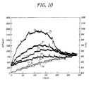
- Fig. 10 is shown a comparison between the conventional checkered honeycomb cordierite filter and the checkered SiC honeycomb filter according to the invention illustrating a change of pressure loss ⁇ P with the lapse of time when a gas oil containing a fuel additive is used while gradually raising a temperature T of the exhaust gas.
- a curve Pc shows a change of pressure loss in the conventional checkered cordierite honeycomb filter having a cell structure Cs (mil/cpi) of 17/100
- curves P1, P2 and P3 show a change of pressure loss in the checkered SiC honeycomb filter according to the invention having cell structures Cs (mil/cpi) of 17/100, 14/200 and 12/300, respectively.
- the conventional cordierite filter is compared with the SiC filter at the same cell structure.
- the change of pressure loss by the collection of particulates included in the exhaust gas Gin becomes equilibrium at an exhaust gas temperature Tc of about 380°C or at a pressure loss ⁇ P of not less than 1750 mmAq as shown by the curve Pc in Fig. 10.
- the particulate is burnt by raising the exhaust gas temperature Tc to a given level, whereby the pressure loss is largely reduced.
- Such a large change of pressure loss Pc brings about the bad feeling in the running of the vehicle.
- the exhaust gas temperature is raised by pressing down an accelerator toward a floor, rapid burning of the particulate and rapid reduction of pressure loss are simultaneously caused to increase the engine revolution number to an unexpected level of a driver.
- the change of pressure loss becomes equilibrium at an exhaust gas temperature T1 of about 380°C or at a pressure loss ⁇ P of 1250 mmAq as shown by the curve P1 in Fig. 10. Even when the particulate is burnt by raising the exhaust gas temperature T1 to a given level in the same manner as in the cordierite filter, the change of pressure loss is small, which brings about comfortable feeling in the running of the vehicle.
- the amount of the particulate caught when the change of pressure loss is at the equilibrium state is the same in any one of the above filters and the value of the equilibrium pressure loss becomes low as the cell structure of the filter becomes fine. And also, when the particulate is burnt by raising the exhaust gas temperature, the pressure loss returns to substantially the same level in the same treating time in all of these filters. Furthermore, as the level of pressure loss becomes lower, the change of pressure loss is small. From these facts, it can be seen that it is favorable to use a filter having a lower level of pressure loss as a honeycomb filter for cleaning the exhaust gas for improving the fuel consumption.
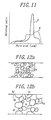
- Fig. 11 is shown a pore size distribution in a cell wall in the conventional cordierite filter and the SiC honeycomb filter according to the invention, wherein a solid line A indicates the cell wall of the SiC filter and a dot-dash line B indicates the cell wall of the cordierite filter.
- the cordierite filter has two peaks at lower side and higher side of pore size, while the SiC filter has a single sharp peak. This shows that the SiC filter has a structure having substantially the uniform pore size and the cordierite filter has a structure having ununiform pore size distribution.
- FIG. 12a An inner structure of the cell wall in the SiC filter is shown in Fig. 12a, while an inner structure of the cell wall in the conventional cordierite filter is shown in Fig. 12b.
- pores h having substantially a constant pore size are connected to each other in the cell wall of the SiC filter, which are easy to pass a fluid such as an exhaust gas or the like.
- pores h having various pore sizes are connected to each other in the cell wall, while closed pores hc having a smaller pore size are independently existent therein.
- the interconnected pores in the cell wall contribute to decrease ⁇ P3 in the aforementioned equation (1) at a state that the particulates are not yet deposited on the cell wall, which makes the initial pressure loss ⁇ Pi small at any flow rates Va.
- the particulates included in the exhaust gas are concentrically deposited on surface portions of the cell wall existing pores having a large pore size located near to the surface of the cell wall to cover such surface portions, and hence the pass of the exhaust gas through portions of such large-size pores covered with the particulate is obstructed to rapidly increase the pressure loss though the pores having relatively small pore size located near to the surface of the cell wall contribute to decrease the pressure loss.
- the initial pressure loss ⁇ Pi is equal to that of the cordierite filter.
- the pore size of the interconnected pores in the cell wall is substantially constant and the pore size distribution is uniform, when the exhaust gas is passed through the filter, the particulates included in the exhaust gas are equally deposited over the full surface of the cell wall, so that there is caused no rapid increase of the pressure loss as in the cordierite filter. And also, the value of the pressure loss becomes lower than that of the cordierite filter.
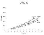
- Fig. 13 is shown a relation between initial pressure loss ⁇ Pi (mmAq) and air flow rate Va (m/sec) at 20°C in the checkered SiC honeycomb filter having a side of 33 mm and a length of 150 mm and a cell structure Cs (mil/cpi) of 17/100, 14/200 or 12/300.
- the initial pressure loss is proportional to the air flow rate supplied to the filter.
- the value of the initial pressure loss lowers as the cell number becomes large and the thickness of the cell wall becomes thin. In other words, the pass of air through the filter becomes more easy as the value of the initial pressure loss becomes lower. This is true in the results shown in Fig. 10. That is, the change of pressure loss becomes small as the value of the initial pressure loss becomes lower.
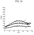
- Fig. 14 is shown an influence of a diameter ⁇ of a filter in the checkered SiC honeycomb filter upon the pressure loss ⁇ P when the particulate included in the exhaust gas is caught by the filter having a cell structure Cs (mil/cpi) of 14/200 with the lapse of time, wherein a curve P4 is a case that the filter diameter ⁇ is 144 mm, and a curve P5 is a case that the filter diameter ⁇ is 165 mm, and a curve P6 is a case that the filter diameter ⁇ is 190 mm.
- the pressure loss and the change thereof can be made small as the volume of the filter becomes larger.
- the total volume of the filter is determined by the engine swept volume of the internal combustion engine used.
- the total volume of the filter is set to 1/4-2 times the engine swept volume of the internal combustion engine when cell structure of the filter is the same.
- the pressure loss ⁇ P becomes too large as seen from Fig. 14 to considerably degrade the fuel consumption
- the pressure loss can be made small, but the total volume of the exhaust gas cleaning device inclusive of the filter is too large and hence such a device can not be disposed in the exhaust emission path for the internal combustion engine.
- Fig. 15 is shown a relation between oxygen concentration (%) in an exhaust gas and a particulate burning temperature (°C) for attaining a regeneration ratio of not less than 80% (shown by a shadowed region) in the checkered honeycomb SiC filter after a given amount (10 g/L) of the particulate is caught by the filter.
- the SiC filter has a cell structure Cs (mil/cpi) of 14/200 and a regeneration gas having various oxygen concentrations at a temperature of 150°C as a substitute for the exhaust gas is introduced into the filter at a flow rate Va of 2.5 m/sec.
- the term "regeneration ratio" used herein means a percentage of filter weight after the introduction of the regeneration gas to filter weight before the introduction of the regeneration gas.
- a shadowed region of a curve a is a region for attaining the regeneration ratio of not less than 80% when particulates deposited on the SiC filer from a diesel engine using a gas oil containing a fuel additive is burnt by the glow plug 34
- a shadowed region of a curve b is a region for attaining the regeneration ratio of not less than 80% when particulates deposited on the SiC filer from a diesel engine using only a gas oil containing no fuel additive is burnt by a heater.
- the oxygen concentration in the exhaust gas is required to be not less than at least 15% and also it is required to heat the filter above about 650°C by the heater for burning the particulate.
- the gas oil containing the fuel additive is used in the diesel engine, so that the particulate burning temperature is sufficient to be at least 150°C, and also even when the oxygen concentration in the exhaust gas is as low as 3%, it is enough to heat the filter at a temperature considerably lower than that of the curve b by the heater or the glow plug.
- the usual size of the filter can be utilized as it is without increasing the volume of the filter, so that the regeneration system for the exhaust gas cleaning device of the illustrated embodiment is effective to a vehicle having a large displacement such as truck and bus having a displacement of 12 liter.
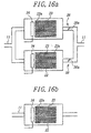
- the illustrated embodiment is described with respect to the branched structure of three regeneration units, the invention may take a branched structure wherein two regeneration units are arranged side by side in the exhaust emission path 11 as shown in Fig. 16a or a structure of arranging a single regeneration unit in the exhaust emission path 11 as shown in Fig. 16b.
- the two branched structure shown in Fig. 16a is used in a truck having a displacement of, for example, 7 liter, wherein the control of the two regeneration units can be carried out by the same method as in the three-branched structure shown in Fig. 4. That is, the flow control valve 26 and the glow plug 34 in each of the two regeneration units are controlled by a command from the control unit (not shown), whereby the exhaust gas is cleaned by the filter in one of the regeneration units at a non-worked state of a valve body 26a in the flow control valve 26, while the filter of the other regeneration unit at a worked state of a valve body 26a of the flow control valve 26 is regenerated by heating such a filter through the glow plug 34.
- the single structure shown in Fig. 16b is used in a passenger car having a displacement of, for example, 3 liter, wherein the control of the regeneration unit is carried out by switching on or off only the glow plug 34 without using the flow control valve because the purification of the exhaust gas and the regeneration of the filter are simultaneously carried out.
Description
- This invention relates to a regeneration system for an exhaust gas cleaning device, and more particularly to a regeneration system comprising an exhaust gas cleaning device disposed in an exhaust emission path of an internal combustion engine and provided with an exhaust gas cleaning honeycomb filter for catching particulates included in the exhaust gas and a heating means for the exhaust gas cleaning honeycomb filter when a fuel containing a fuel additive for mitigating particulates included in the exhaust gas is used as a fuel for the internal combustion engine.
- In the internal combustion engine such as diesel engine or the like, particulates (e.g. soot or unburned portion of fuel) are included in the exhaust gas. Particularly, the discharge amount of particulates becomes large in a diesel engine using a gas oil as a fuel or a direct-injection type gasoline engine recently coming into wide use. Therefore, it is well-known to remove the particulates by an exhaust gas cleaning device disposed in an exhaust emission path of the internal combustion engine and provided with an exhaust gas cleaning honeycomb filter.
- As the exhaust gas cleaning honeycomb filter is generally used a
cordierite filter 32 of a honeycomb structure as shown by a diagrammatically section view in Fig. 1. In such aconventional cordierite filter 32 are included a plurality of exhaustgas flowing channels 33 extending in parallel to a longitudinal direction thereof, wherein thesechannels 33 are alternately plugged at either upstream side or downstream side for the exhaust gas of their ends with pluggingmembers 33a to form a checker pattern. - As shown in Fig. 1, an exhaust gas Gin emitted from a diesel engine (not shown) flows into the
cordierite filter 32 through theexhaust emission path 11, at where particulates included in the exhaust gas are filtered off on surfaces of cell walls constituting the exhaustgas flowing channels 33. Then, the cleaned exhaust gas Gout passed throughcordierite filter 32 again passes through theexhaust emission path 11 and is discharged out to the outside of the vehicle. - It is known that pressure loss ΔP is produced when the exhaust gas Gin passes through the
filter 32. The pressure loss ΔP is represented by the following equation (1).gas flowing channel 33 when the exhaust gas flows into thechannel 33 through theexhaust emission path 11; - ΔP2 is a resistance produced in the flowing of the exhaust gas through
the exhaust
gas flowing channel 33; - ΔP3 is a resistance produced in the passing through a wall of the exhaust
gas flowing channel 33; - ΔP4 is a resistance produced when the exhaust gas passes through
particulates deposited on the surface of the exhaust
gas flowing channel 33. -
- In this case, the resistances ΔP1, ΔP2, ΔP3 are dependent upon a cell structure constituting the
filter 32, respectively and are a constant value ΔPi not depended upon the lapse of time coming into problem in the deposition of the particulates and the like (hereinafter "ΔP1 + ΔP2 + ΔP3" is called as "initial pressure loss"). For this end, a greater part of the pressure loss ΔP is determined by the resistance ΔP4 produced when the exhaust gas passes through the particulates deposited on the cell walls. The resistance ΔP4 is usually 2-3 times the initial pressure loss ΔPi at a deposited state of the particulates. - In Fig. 2 is shown a relation among cell structure, typical dimensions, geometrical surface area and opening ratio in the filter. The cell structure Cs (mil/cpi) is represented by thickness of cell wall dc (mil = milli inch) to cell number Nc per square inch (cpi = cells per square inch), and the geometrical surface area fs (cm2/cm3) is an area passing the exhaust gas per unit volume (filtering area). Moreover, the cell wall thickness dc is shown by unit of mm in Fig. 2.
- As seen from Fig. 2, the pressure loss ΔP produced in the checkered honeycomb filter for cleaning the exhaust gas is small as the cell number Nc and geometrical surface area fs in the filter become large. And also, the opening ratio α (%) is a ratio of total opening area of the exhaust gas flowing channels occupied in the sectional area of the filter. As shown in Fig. 2, a limit not creating cracks (crack limit) is large as the opening ratio α becomes small.
- On the other hand, a mechanical strength of the filter, i.e. bending strength S* of the filter is approximately equal to product of strength S of a filter made of porous material and relative density ρ* as mentioned below. When the nature of the porous material constituting the filter is represented by density ρ and strength S, the bending strength S* of the filter and the relative density ρ* are as follows:
- Further, the regeneration of the filter is carried out by burning the particulates according to the following reaction equation (4):
- Therefore, the exhaust gas cleaning filter having good properties is preferably made of a material having a large crack limit, an excellent strength against thermal stress and a small pressure loss.
- Recently, fuel previously including a fuel additive, or a device dropwise adding a fuel additive to a fuel is developed for controlling the amount of the particulate produced in the exhaust gas and the use thereof is increasing. Such a fuel additive has an effect of preventing the formation of soot in the burning of the fuel.
- However, the formation of the particulate can not completely be controlled even by using such a fuel additive and hence the particulate is formed in the exhaust gas. Therefore, it is indispensable to use the exhaust gas cleaning filter.
- In the conventional technique, the cordierite filter is generally adopted as a checkered honeycomb filter for cleaning the exhaust gas as previously mentioned. However, there is a problem that the amount of the particulate to be treated in one regeneration of the cordierite filter has a limit because the maximum service temperature in the filter is low. In this case, a large pressure loss is caused in the filter due to the deposition of the particulate, so that the combustion efficiency of the internal combustion engine lowers to degrade the fuel consumption.
- And also, there is proposed a technique for regenerating the exhaust gas cleaning device by burning the particulate caught on the cordierite filter through a heating means for the filter. However, when such a greater amount of the particulate caught on the filter is burnt out by the heating means at once, a large change of the pressure loss is caused in the burning of the particulate in accordance with the heat conduction efficiency of the heating means, which gives incompatible feeling to a driver.
- In Fig. 3 are shown experimental data illustrating a relation among pressure loss ΔP (mmAq) and temperature T (°C) and time t (min) in the conventional checkered honeycomb cordierite filter for cleaning the exhaust gas. In Fig. 3, symbol Po is a case of burning a fuel containing a fuel additive, wherein as the temperature T rises with the increase of engine revolution number (engine loading), the deposition of particulates begins to decrease on the border of a certain time. That is, the burning of the particulate is begun at a temperature of To = about 380°C to conduct the regeneration of the filter.
- On the other hand, symbol Pn is a case of burning a fuel containing no fuel additive, wherein the pressure loss ΔP in the filter continuously rises in proportion to the deposition of the particulate even when the temperature Tn rises with the increase of the engine revolution number (engine loading). As a result, the burning of the particulate at a temperature of Tn = about 380°C is not carried out different from the case of burning the fuel containing the fuel additive. Moreover, the beginning temperature of burning the particulates in case of using the fuel containing no fuel additive is generally about 630°C.
- In order to reduce the pressure loss produced in the cordierite filter, therefore, it is considered to finely set the cell structure Cs of the cordierite filter with reference to Fig. 2. For example, it is considered that the cell number Nc (cpi) is set to a large value, while the thickness dc of the cell wall is set to a small value.
- In the conventional cordierite filter, however, there is a limit in the formation of the fine cell structure from a view point of the strength inherent to the cordierite. For example, it is possible to manufacture the cordierite honeycomb filter having the cell number Nc of more than 100 cpi, but when such a filter is used as a checkered honeycomb filter capable of efficiently burning the particulate, the cracking is caused in view of the crack limit of cordierite itself, so that the cell number Nc (cpi) can not be made more than 100 when the checkered honeycomb filter for cleaning the exhaust gas is made of cordierite.
- In addition, if it is intended to burn the deposited particulates through only the temperature of the exhaust gas, there is caused an inconvenience that the honeycomb filter for cleaning the exhaust gas can not completely be regenerated because the exhaust gas may not rise to a temperature required for burning the particulate when the vehicle is frequently run on urban area at a low speed.
- DE 4021033A1 discloses a prior art exhaust cleaner for an internal combustion engine of a motor vehicle. The cleaner is provided with porous silicon-carbide filter in thermally insulating mounting for burning off carbon deposits. The thermal conductivity of the silicon carbide is used to ensure rapid burn of the carbon when the integral electric heating element is powered. The heating can be provided by a direct electric element, microwave heating or hot gas heating.
- Under the above situations, it is an aim of the invention to provide a regeneration system for an exhaust gas cleaning device disposed in an exhaust emission path of an internal combustion engine capable of controlling a change of pressure loss to a smaller value during the regeneration and conducting the complete regeneration of the filter even at a running state hardly raising the temperature of the exhaust gas by using an exhaust gas cleaning honeycomb filter made of a porous silicon carbide sintered body, which can be set to a fine cell structure and is high in the crack limit and excellent in the strength against thermal stress, together with a heating means for the filter when a fuel containing a fuel additive is used as a fuel for the internal combustion engine.
- The invention provides a regeneration system for an exhaust gas cleaning device disposed in an exhaust emission path of an internal combustion engine comprising an exhaust gas cleaning honeycomb filter for collecting particulates included in the exhaust gas and a heating means for the exhaust gas cleaning honeycomb filter, said filter is a checked honeycomb filter made of a porous silicon carbide sintered body and having a cell structure wherein the cell number per square inch is not less than 100 cells and wherein the thickness of a cell wall is not more than 0.43 mm, and said heating means is selected from a heater and a glow plug and disposed in front of an upstream end face of the filter to heat the exhaust gas characterised in that said internal combustion engine uses a gas oil containing a fuel additive for controlling the amount of particulates produced in the exhaust gas and to obtain a particulate burning temperature of at least 150°C sufficient for attaining a filter regeneration ratio of not less than 80%.
- In a preferably embodiment of the invention, the glow plug is a ceramic glow plug.
- In another preferably embodiment of the invention, the filter has a total volume corresponding to 1/4-2 times an engine swept volume of the internal combustion engine.
- In the invention, the exhaust gas cleaning honeycomb filter is a checkered SiC honeycomb filter made of a porous silicon carbide sintered body, so that it is high in the crack limit and excellent in the strength against thermal stress as compared with those of the conventional cordierite filter and hence the durability of the filter is high. And also, the checkered SiC honeycomb filter has a cell structure that the cell number per square inch is not less than 100 cells and the thickness of the cell wall is not more than 0.43 mm (=17 mil), which can be made finer than that of the conventional cordierite filter, so that the pressure loss can be decreased as compared with that of the cordierite filter to improve the fuel consumption.
- Furthermore, in the regeneration system according to the invention, the heater or the glow plug as the heating means for the exhaust gas cleaning filter is arranged ahead the filter in the exhaust gas cleaning device, so that even if the temperature of the exhaust gas is not raised to a level required for burning the particulate during the running of the vehicle on urban area at a low speed or the like, the particulate can be burned by heating the filter through such a heating means, and hence the regeneration of the filter can completely be attained.
- In case of using the glow plug, the space in the exhaust gas cleaning device can be saved and power consumption can be decreased as compared with those in the use of the heater. As the glow plug, there are a metal glow plug and a ceramic glow plug. The use of the ceramic glow plug is favorable because the time reaching to a given temperature by heating is faster than that of the metal glow plug and a saturated temperature can be made higher. And also, the ceramic glow plug is small in the power consumption as compared with the metal glow plug and is high in the durability. Therefore, the more efficient regeneration of the filter can be attained by the use of the ceramic glow plug as compared with the use of the heater or the metal glow plug.
- In the invention, the total volume of the exhaust gas cleaning filter is set to 1/4-2 times the engine swept volume of the internal combustion engine because the total volume is dependent upon the engine swept volume. When the total volume of the filter is less than 1/4 times the engine swept volume, the sufficient filtering area can not be ensured and the pressure loss becomes larger to bring about the remarkable degradation of the fuel consumption, while when it exceeds 2.0 times, it is difficult to arrange the exhaust gas cleaning device inclusive of the filter in the exhaust emission path but also the thermal capacity becomes larger to delay reaction to the temperature of the exhaust gas to thereby lose a chance of obtaining a regeneratable temperature of the filter for burning the particulate.
- The invention will be described with reference to the accompanying drawings, wherein:
- Fig. 1 is a diagrammatically section view illustrating the conventional checkered cordierite honeycomb filter for cleaning exhaust gas;
- Fig. 2 is a graph showing a relation among cell structure, typical dimensions, geometrical surface area and opening ratio in the filter;
- Fig. 3 is a graph showing a pressure loss produced when a checkered honeycomb filter for cleaning exhaust gas is made of cordierite in consideration with the presence or absence of a fuel additive as a function of temperature and time in the filter;
- Fig. 4 is a block schematic diagram of a first embodiment of the regeneration system for the exhaust gas cleaning device according to the invention;
- Fig. 5 is a diagrammatically section view of a main part in the regeneration system according to the invention shown in Fig. 4;
- Fig. 6a is a perspective view of a checkered honeycomb SiC filter for cleaning an exhaust gas according to the invention;
- Fig. 6b is a partial front view of the checkered honeycomb SiC filter shown in Fig. 6a;
- Fig. 7a is a diagrammatic view partly shown in section of a ceramic glow plug used as a heating means;
- Fig. 7b is a diagrammatic view partly shown in section of a metal glow plug used as a heating means;
- Fig. 8 is a view showing a comparison in properties between the ceramic glow plug and the metal glow plug;
- Fig. 9 is a chart illustrating a time period until a given pressure loss is caused by the presence or absence of an exhaust gas purification catalyst for an exhaust gas cleaning device;
- Fig. 10 is a graph showing a comparison in pressure loss between a checkered SiC honeycomb filter and a checkered cordierite honeycomb filter when using a gas oil containing a fuel additive;
- Fig. 11 is a graph showing a pore size distribution of a cell wall in the conventional cordierite filter and the SiC filter according to the invention;
- Fig. 12a is a diagrammatic view of an inner structure of a cell wall in the SiC filter according to the invention;
- Fig. 12b is a diagrammatic view of an inner structure of a cell wall in the conventional cordierite filter;
- Fig. 13 is a graph showing a relation between initial pressure loss and air flow rate in the checkered honeycomb SiC filter;
- Fig. 14 is a graph showing an influence of a diameter of the checkered SiC honeycomb filter upon pressure loss ΔP when using a gas oil containing a fuel additive;
- Fig. 15 is a graph showing a relation between oxygen concentration in exhaust gas and temperature burning particulate for attaining a regeneration ratio of not less than 80% in the exhaust gas cleaning filter when the invention is compared with the conventional technique; and
- Figs. 16a and 16b are diagrammatic views illustrating another embodiments of the regeneration system according to the invention.
-
- In Fig. 4 is shown a first embodiment of the regeneration system for the exhaust gas cleaning device for use in a diesel engine according to the invention. This system is a system for the regeneration of an exhaust
gas cleaning device 20 cleaning the exhaust gas discharged from adiesel engine 10 using a gas oil containing a fuel additive, and comprises three regeneration units 12-1, 12-2, 12-3 disposed on a way of anexhaust emission path 11 from theengine 10 in a branched form. Each of these units comprises an exhaustgas cleaning device 20 provided with an exhaustgas cleaning filter 22 made of a porous silicon carbide (SiC) sintered body and carried with a catalyst for exhaust gas purification, a heating means 24 disposed ahead an end face of theSiC filter 22 at an upstream side thereof for heating theSiC filter 22, and aflow control valve 26 disposed at a downstream side of theSiC filter 22. Further, the regeneration system comprises acontrol unit 40 for controlling power supplied to the heating means 24 and theflow control valve 26. Thecontrol unit 40 is connected to abattery 28 mounted on a vehicle (not shown) and controls the heating means 24 and theflow control valve 26 independently. - The
control unit 40 comprises aninput part 42 inputted with measured values of engine revolution number Ne (rpm) and pressure loss ΔP (mmAq) and temperature T in an exhaustgas cleaning device 20, CPU (central processing unit) 44 processing output signals from theinput part 42 for controlling actions of the heating means 24 and theflow control valve 26, aheater controlling unit 46 operating the heating means 24 based on the processed result inCPU 44, and anoutput part 48 operating theflow control valve 26 to a throttle position (see a position of avalve body 26a in the regeneration unit 12-1 of Fig. 4). - As shown in Fig. 5, the heating means 24 is a spiral-shaped resistance heating heater disposed apart from the upstream end face of the
SiC filter 22 at a given distance. The heater is not restricted to the above spiral form and may take any forms as long as the exhaust gas from theengine 10 is passed in the arrangement ahead theSiC filter 22. Moreover, the kind of the heater is not particularly restricted, but a sheathed heater and the like may be used. - The
honeycomb filter 22 for cleaning the exhaust gas will be described in detail below. In Fig. 5 is diagrammatically shown a first regeneration unit 12-1 among the three regeneration units 12-1, 12-2 and 12-3 in the exhaust gas cleaning device. As shown in Fig. 5, thehoneycomb filter 22 for cleaning the exhaust gas is made of a porous silicon carbide (SiC) sintered body of a honeycomb structure. In such aSiC honeycomb filter 22 are formed a plurality of exhaustgas flowing channels 23 extending in parallel to a longitudinal direction thereof, wherein thesechannels 23 are alternately plugged at either inlet side or outlet side for the exhaust gas of their ends with pluggingmembers 23a to form a checker pattern. That is, the exhaust gas cleaninghoneycomb filter 22 made of the porous silicon carbide sintered body is a checkered SiC honeycomb filter having a given cell wall thickness dc at the upstream and downstream end faces thereof (see Fig. 6). - When using a fuel containing a fuel additive, harmful components included in the exhaust gas is decreased but are not completely removed as previously mentioned. Therefore, it is favorable to carry a catalyst for the purification of the exhaust gas on an inner wall surface of the exhaust
gas flowing channel 23 for removing these harmful components. As the catalyst for the purification of the exhaust gas, use may be made of the conventionally known catalysts. Moreover, the checkeredSiC honeycomb filter 22 is closely held in a casing of the exhaustgas cleaning device 20 through aheat insulating material 23b arranged on the outer periphery of the filter. - The checkered SiC honeycomb filter according to the invention is made of the porous silicon carbide sintered body so as to have a cell structure that the cell number Nc per square inch is not less than 100 cells and a cell wall thickness dc is not more than 0.43 mm (= 17 mil). As a numerical value of a more preferable cell structure Cs (mil/cpi), there are concretely mentioned Cs = 14/200, 12/200, 12/300 and the like.
- A second embodiment of the regeneration system for the exhaust gas cleaning device for use in a diesel engine according to the invention has the same structure as in the first embodiment except that a
glow plug 34 is used instead of the heater as the heating means 24 as shown in Fig. 7. As theglow plug 34, there are two plugs as shown in Figs. 7a and 7b. The plug shown in Fig. 7a is aceramic glow plug 34a using an electrically conductive ceramic 35 attached to a top of the plug as a heating portion, wherein heat is generated by flowing current through the electrically conductive ceramic 35. The plug shown in Fig. 7b is ametal glow plug 34b using aheating coil 36 attached to the top of the plug as a heating part, wherein heat is generated by flowing current through theheating coil 36. - In Fig. 8 is shown a comparison in properties between the
ceramic glow plug 34a and themetal glow plug 34b. In this case, the time reaching to 800°C by heating is a surface temperature rising rate of the heating portion at the top of the plug, and the saturated temperature is a temperature when the surface temperature of the glow plug arrives at a saturated state or a temperature capable of conducting the burning at a stable state. - As seen from Fig. 8, the time reaching to 800°C by heating is 3.5 seconds in the
ceramic glow plug 34a and 5.5 seconds in themetal glow plug 34b. On the other hand, the saturated temperature is 1100°C in theceramic glow plug 34a, while that in themetal glow plug 34b is as low as 900°C. And also, the power consumption per one plug is 36 W in theceramic glow plug 34a, while that in themetal glow plug 34b is required to be 55 W. Further, service life of theceramic glow plug 34a converted to a running distance is not less than 200,000 km, while that of themetal glow plug 34b is about 100,000 km. - Therefore, when the
ceramic glow plug 34a is compared with themetal glow plug 34b, it is effective to use theceramic glow plug 34a as a glow plug used as a heating means for the filter. - The action of the regeneration system according to the invention will be described with reference to Figs. 4 and 5 below. Although the action is described by using the
ceramic glow plug 34b as the heating means 24, the similar action and effect are obtained even when the heater or the metal glow plug is used as the heating means 24. - When the exhaust gas Gin emitted from the diesel engine using a gas oil containing a fuel additive is flowed into the checkered
SiC honeycomb filter 22 at a state of mitigating the amount of particulate in the exhaust gas owing to the use of the fuel additive, the particulate included in the exhaust gas is filtered off on the surfaces of the exhaustgas flowing channels 23. Thus, the exhaust gas Gout cleaned through the checkeredhoneycomb SiC filter 22 is again flowed into theexhaust emission path 11 and discharged out therefrom to the outside of the vehicle. - When the diesel engine is worked over a long time, the particulate included in the exhaust gas is gradually deposited on the inner wall surfaces of the
channels 23. Therefore, it is required to regenerate the exhaust gas cleaning device by heating the honeycomb SiC filter every a given time during the working of the diesel engine. - During the running of the vehicle, the
flow control valve 26 in each of the three regeneration units 12-1, 12-2, 12-3 is at a non-worked state, so that when the exhaust gas Gin is passed through the exhaustgas cleaning device 22, the particulate included in the exhaust gas Gin is filtered off by theSiC honeycomb filter 22 and gradually deposited on the inner wall surfaces of thechannels 23 in thefilter 22. - When a given amount of the particulate is caught on the inner wall surface of the
channel 23, it is difficult to pass the exhaust gas Gin through thechannel 23, so that the temperature inside the exhaustgas cleaning device 22 rapidly rises. When the temperature inside the cleaning device reaches to a given value with such a temperature rise, the particulate is burnt out by reacting with oxygen included in the exhaust gas Gin. In the running on urban area and the like frequently using low-speed running, however, there is a case that the temperature of the exhaust gas is not raised to a level required for burning the particulate. - In the regeneration system according to the invention, when the particulate is caught on the surface of the channel over a certain time, for example, only the regeneration unit 12-1 among the three regeneration units 12-1, 12-2, 12-3 is worked, while the other regeneration units 12-2, 12-3 are maintained at the non-worked state. That is, the
ceramic glow plug 34a in the regeneration unit 12-1 is switched-on through a circuit R1 by a command from thecontrol unit 40 to heat the end face of theSiC honeycomb filter 22 at the upstream side thereof, while thevalve body 26a of theflow control valve 26 is also worked by a signal V from theoutput part 48 to throttle a flow of the exhaust gas passing through theSiC honeycomb filter 22 at a downstream side of the filter. In the regeneration unit 12-1, therefore, the exhaust gas Gin heated by theceramic glow plug 34a gently passes through theSiC honeycomb filter 22, during which the particulates caught in theSiC honeycomb filter 22 are burnt out by reacting with oxygen included in the exhaust gas. - While the
SiC honeycomb filter 22 in the regeneration unit 12-1 is regenerated by controlling only theceramic glow plug 34a and theflow control valve 26 through thecontrol unit 40, the exhaust gas is cleaned by the other remaining regeneration units 12-2 and 12-3. - After the completion of the regeneration in the regeneration unit 12-1, the other remaining regeneration units 12-2 and 12-3 are successively regenerated in the same manner as described above through the command from the
control unit 40. Therefore, the regeneration units 12-1, 12-2, 12-3 are separately and successively regenerated during the running of the vehicle, which is fairly economical as compared with the case of regenerating these regeneration units after the running of the vehicle is stopped. - The effect by the provision of an oxidation catalyst on the inner wall surface of the exhaust
gas flowing channel 23 in theSiC honeycomb filter 22 will be described in detail below. - In Fig. 9 is a chart illustrating a time period until a given pressure loss is caused by the presence or absence of the oxidation catalyst as a catalyst for the purification of the exhaust gas in the exhaust gas cleaning device.
- Fig. 9a shows a case that a diesel bus provided with an exhaust gas cleaning device using no oxidation catalyst is run on urban area at a usual low-speed, wherein a regeneration period of the
SiC honeycomb filter 22 at a pressure loss of 3000 mmAq produced when 40 g of particulates are caught as a measure of beginning the regeneration is 2 hours. On the contrary, Figs. 9b and 9c show a case of using an exhaust gas cleaning device with an oxidation catalyst, respectively, wherein the regeneration period based on the pressure loss of 3000 mmAq is 4 hours in the low-speed running on urban area or the like as shown in Fig. 9b and 8 hours in the high-speed running on suburbs and expressways as shown in Fig. 9c. - As seen from these charts, when the oxidation catalyst is carried on the inner wall surface of the exhaust
gas flowing channel 23 in theSiC honeycomb filter 22, the operation period for the regeneration system can be delayed during the running of the vehicle, which is effective to improve the durabilities of theceramic glow plug 34a and theflow control valve 26. Moreover, the running mode of the vehicle is usually a mixed mode of low-speed running and high-speed running, so that the operation of the regeneration system is desirable to be begun every 3-4 hours as seen from Figs. 9b and 9c. - In Fig. 10 is shown a comparison between the conventional checkered honeycomb cordierite filter and the checkered SiC honeycomb filter according to the invention illustrating a change of pressure loss ΔP with the lapse of time when a gas oil containing a fuel additive is used while gradually raising a temperature T of the exhaust gas. In this case, a curve Pc shows a change of pressure loss in the conventional checkered cordierite honeycomb filter having a cell structure Cs (mil/cpi) of 17/100, and curves P1, P2 and P3 show a change of pressure loss in the checkered SiC honeycomb filter according to the invention having cell structures Cs (mil/cpi) of 17/100, 14/200 and 12/300, respectively.
- At first, the conventional cordierite filter is compared with the SiC filter at the same cell structure. In the conventional cordierite filter, when the particulate included in the exhaust gas is caught to a given amount by the filter, the change of pressure loss by the collection of particulates included in the exhaust gas Gin becomes equilibrium at an exhaust gas temperature Tc of about 380°C or at a pressure loss ΔP of not less than 1750 mmAq as shown by the curve Pc in Fig. 10. After the lapse of a given time at the equilibrium state, the particulate is burnt by raising the exhaust gas temperature Tc to a given level, whereby the pressure loss is largely reduced. Such a large change of pressure loss Pc brings about the bad feeling in the running of the vehicle. Particularly, when the exhaust gas temperature is raised by pressing down an accelerator toward a floor, rapid burning of the particulate and rapid reduction of pressure loss are simultaneously caused to increase the engine revolution number to an unexpected level of a driver.
- In the checkered SiC honeycomb filter according to the invention having the same cell structure as in the cordierite filter, when the particulate is caught by the filter to the same amount as in the cordierite filter, the change of pressure loss becomes equilibrium at an exhaust gas temperature T1 of about 380°C or at a pressure loss ΔP of 1250 mmAq as shown by the curve P1 in Fig. 10. Even when the particulate is burnt by raising the exhaust gas temperature T1 to a given level in the same manner as in the cordierite filter, the change of pressure loss is small, which brings about comfortable feeling in the running of the vehicle.
- Then, when the cell structure of the SiC filter is changed from 17/100 to 14/200 or 12/300, the change of pressure loss when the same amount of the particulate is caught becomes equilibrium at a pressure loss ΔP of about 950 mmAq or about 700 mmAq, respectively, at the exhaust gas temperature T of about 380°C. That is, as the thickness of the cell wall becomes thin and the cell number becomes large, the value of the equilibrium pressure loss becomes low and hence the change of pressure loss becomes small.
- As seen from Fig. 10, the amount of the particulate caught when the change of pressure loss is at the equilibrium state is the same in any one of the above filters and the value of the equilibrium pressure loss becomes low as the cell structure of the filter becomes fine. And also, when the particulate is burnt by raising the exhaust gas temperature, the pressure loss returns to substantially the same level in the same treating time in all of these filters. Furthermore, as the level of pressure loss becomes lower, the change of pressure loss is small. From these facts, it can be seen that it is favorable to use a filter having a lower level of pressure loss as a honeycomb filter for cleaning the exhaust gas for improving the fuel consumption.
- In Fig. 11 is shown a pore size distribution in a cell wall in the conventional cordierite filter and the SiC honeycomb filter according to the invention, wherein a solid line A indicates the cell wall of the SiC filter and a dot-dash line B indicates the cell wall of the cordierite filter. As seen from Fig. 11, the cordierite filter has two peaks at lower side and higher side of pore size, while the SiC filter has a single sharp peak. This shows that the SiC filter has a structure having substantially the uniform pore size and the cordierite filter has a structure having ununiform pore size distribution.
- An inner structure of the cell wall in the SiC filter is shown in Fig. 12a, while an inner structure of the cell wall in the conventional cordierite filter is shown in Fig. 12b. As seen from Fig. 12a, pores h having substantially a constant pore size are connected to each other in the cell wall of the SiC filter, which are easy to pass a fluid such as an exhaust gas or the like. In the cordierite filter, as seen from Fig. 12b, pores h having various pore sizes are connected to each other in the cell wall, while closed pores hc having a smaller pore size are independently existent therein.
- In case of the conventional checkered honeycomb cordierite filter, the interconnected pores in the cell wall contribute to decrease ΔP3 in the aforementioned equation (1) at a state that the particulates are not yet deposited on the cell wall, which makes the initial pressure loss ΔPi small at any flow rates Va. However, as the exhaust gas gradually passes through the filter, the particulates included in the exhaust gas are concentrically deposited on surface portions of the cell wall existing pores having a large pore size located near to the surface of the cell wall to cover such surface portions, and hence the pass of the exhaust gas through portions of such large-size pores covered with the particulate is obstructed to rapidly increase the pressure loss though the pores having relatively small pore size located near to the surface of the cell wall contribute to decrease the pressure loss.
- On the other hand, in the checkered SiC honeycomb filter according to the invention having the same cell structure as in the cordierite filter, the initial pressure loss ΔPi is equal to that of the cordierite filter. However, since the pore size of the interconnected pores in the cell wall is substantially constant and the pore size distribution is uniform, when the exhaust gas is passed through the filter, the particulates included in the exhaust gas are equally deposited over the full surface of the cell wall, so that there is caused no rapid increase of the pressure loss as in the cordierite filter. And also, the value of the pressure loss becomes lower than that of the cordierite filter.
- In Fig. 13 is shown a relation between initial pressure loss ΔPi (mmAq) and air flow rate Va (m/sec) at 20°C in the checkered SiC honeycomb filter having a side of 33 mm and a length of 150 mm and a cell structure Cs (mil/cpi) of 17/100, 14/200 or 12/300. As seen from Fig. 13, the initial pressure loss is proportional to the air flow rate supplied to the filter. And also, the value of the initial pressure loss lowers as the cell number becomes large and the thickness of the cell wall becomes thin. In other words, the pass of air through the filter becomes more easy as the value of the initial pressure loss becomes lower. This is true in the results shown in Fig. 10. That is, the change of pressure loss becomes small as the value of the initial pressure loss becomes lower.
- In Fig. 14 is shown an influence of a diameter of a filter in the checkered SiC honeycomb filter upon the pressure loss ΔP when the particulate included in the exhaust gas is caught by the filter having a cell structure Cs (mil/cpi) of 14/200 with the lapse of time, wherein a curve P4 is a case that the filter diameter is 144 mm, and a curve P5 is a case that the filter diameter is 165 mm, and a curve P6 is a case that the filter diameter is 190 mm. As seen from Fig. 14, the pressure loss and the change thereof can be made small as the volume of the filter becomes larger.
- As previously mentioned, the total volume of the filter is determined by the engine swept volume of the internal combustion engine used. In the invention, it is favorable that the total volume of the filter is set to 1/4-2 times the engine swept volume of the internal combustion engine when cell structure of the filter is the same. When the total volume is less than 1/4 times the swept engine volume, the pressure loss ΔP becomes too large as seen from Fig. 14 to considerably degrade the fuel consumption, while when the total volume exceeds 2 times the swept engine volume, the pressure loss can be made small, but the total volume of the exhaust gas cleaning device inclusive of the filter is too large and hence such a device can not be disposed in the exhaust emission path for the internal combustion engine.
- In Fig. 15 is shown a relation between oxygen concentration (%) in an exhaust gas and a particulate burning temperature (°C) for attaining a regeneration ratio of not less than 80% (shown by a shadowed region) in the checkered honeycomb SiC filter after a given amount (10 g/L) of the particulate is caught by the filter. In this case, the SiC filter has a cell structure Cs (mil/cpi) of 14/200 and a regeneration gas having various oxygen concentrations at a temperature of 150°C as a substitute for the exhaust gas is introduced into the filter at a flow rate Va of 2.5 m/sec. Moreover, the term "regeneration ratio" used herein means a percentage of filter weight after the introduction of the regeneration gas to filter weight before the introduction of the regeneration gas.
- In Fig. 15, a shadowed region of a curve a is a region for attaining the regeneration ratio of not less than 80% when particulates deposited on the SiC filer from a diesel engine using a gas oil containing a fuel additive is burnt by the
glow plug 34, while a shadowed region of a curve b is a region for attaining the regeneration ratio of not less than 80% when particulates deposited on the SiC filer from a diesel engine using only a gas oil containing no fuel additive is burnt by a heater. - As seen from the curve b in Fig. 15, when using only the gas oil as in the conventional technique, in order to attain the regeneration ratio of not less than 80%, the oxygen concentration in the exhaust gas is required to be not less than at least 15% and also it is required to heat the filter above about 650°C by the heater for burning the particulate. On the contrary, as seen from the curve a in Fig. 15, in order to attain the regeneration ratio of not less than 80% according to the invention, the gas oil containing the fuel additive is used in the diesel engine, so that the particulate burning temperature is sufficient to be at least 150°C, and also even when the oxygen concentration in the exhaust gas is as low as 3%, it is enough to heat the filter at a temperature considerably lower than that of the curve b by the heater or the glow plug.
- According to the embodiment shown in Fig. 4, the usual size of the filter can be utilized as it is without increasing the volume of the filter, so that the regeneration system for the exhaust gas cleaning device of the illustrated embodiment is effective to a vehicle having a large displacement such as truck and bus having a displacement of 12 liter. Although the illustrated embodiment is described with respect to the branched structure of three regeneration units, the invention may take a branched structure wherein two regeneration units are arranged side by side in the
exhaust emission path 11 as shown in Fig. 16a or a structure of arranging a single regeneration unit in theexhaust emission path 11 as shown in Fig. 16b. - The two branched structure shown in Fig. 16a is used in a truck having a displacement of, for example, 7 liter, wherein the control of the two regeneration units can be carried out by the same method as in the three-branched structure shown in Fig. 4. That is, the
flow control valve 26 and theglow plug 34 in each of the two regeneration units are controlled by a command from the control unit (not shown), whereby the exhaust gas is cleaned by the filter in one of the regeneration units at a non-worked state of avalve body 26a in theflow control valve 26, while the filter of the other regeneration unit at a worked state of avalve body 26a of theflow control valve 26 is regenerated by heating such a filter through theglow plug 34. - The single structure shown in Fig. 16b is used in a passenger car having a displacement of, for example, 3 liter, wherein the control of the regeneration unit is carried out by switching on or off only the
glow plug 34 without using the flow control valve because the purification of the exhaust gas and the regeneration of the filter are simultaneously carried out.
Claims (4)
- A regeneration system for an exhaust gas cleaning device (20) disposed in an exhaust emission path (11) of an internal combustion engine (10) comprising an exhaust gas cleaning honeycomb filter (22) for collecting particulates included in the exhaust gas and a heating means (24) for the exhaust gas cleaning honeycomb filter, said filter (22) is a checked honeycomb filter made of a porous silicon carbide sintered body and having a cell structure wherein the cell number per square inch is not less than 100 cells and wherein the thickness of a cell wall is not more than 0.43 mm, and said heating means (24) is selected from a heater and a glow plug and disposed in front of an upstream end face of the filter (22) to heat the exhaust gas characterised in that said internal combustion engine (10) uses a gas oil containing a fuel additive for controlling the amount of particulates produced in the exhaust gas and to obtain a particulate burning temperature of at least 150°C sufficient for attaining a filter regeneration ratio of not less than 80%.
- A regeneration system according to claim 1, wherein the glow plug is a ceramic glow plug.
- A regeneration system according to claim 1 or 2 wherein the filter has a total volume corresponding to 1/4-2 times an engine swept volume of the internal combustion engine.
- A regeneration system according to any preceding claim wherein the heater is a spiral shaped resistance heating heater.
Applications Claiming Priority (6)
| Application Number | Priority Date | Filing Date | Title |
|---|---|---|---|
| JP27737598 | 1998-09-30 | ||
| JP27737698 | 1998-09-30 | ||
| JP27737598 | 1998-09-30 | ||
| JP27737698 | 1998-09-30 | ||
| JP26193099 | 1999-09-16 | ||
| JP11261930A JP2000167329A (en) | 1998-09-30 | 1999-09-16 | Regeneration system for exhaust gas purifying apparatus |
Publications (2)
| Publication Number | Publication Date |
|---|---|
| EP0990777A1 EP0990777A1 (en) | 2000-04-05 |
| EP0990777B1 true EP0990777B1 (en) | 2002-11-27 |
Family
ID=27335077
Family Applications (1)
| Application Number | Title | Priority Date | Filing Date |
|---|---|---|---|
| EP99307673A Expired - Lifetime EP0990777B1 (en) | 1998-09-30 | 1999-09-29 | Regeneration system for an exhaust gas cleaning device |
Country Status (4)
| Country | Link |
|---|---|
| US (2) | US6447564B1 (en) |
| EP (1) | EP0990777B1 (en) |
| JP (1) | JP2000167329A (en) |
| DE (1) | DE69904132T2 (en) |
Cited By (2)
| Publication number | Priority date | Publication date | Assignee | Title |
|---|---|---|---|---|
| US7648547B2 (en) | 2002-04-10 | 2010-01-19 | Ibiden Co., Ltd. | Honeycomb filter for clarifying exhaust gas |
| US8080082B2 (en) | 1999-09-29 | 2011-12-20 | Ibiden Co., Ltd. | Honeycomb filter and method for producing the honeycomb filter |
Families Citing this family (64)
| Publication number | Priority date | Publication date | Assignee | Title |
|---|---|---|---|---|
| JP2000167329A (en) * | 1998-09-30 | 2000-06-20 | Ibiden Co Ltd | Regeneration system for exhaust gas purifying apparatus |
| JP2001329830A (en) * | 2000-03-15 | 2001-11-30 | Ibiden Co Ltd | Regeneration device for exhaust gas purifying filter, and filter regeneration method, regeneration program for exhaust gas purifying filter, and recording medium storing program |
| DE10023787A1 (en) * | 2000-05-15 | 2001-11-22 | Volkswagen Ag | Particle filter for exhaust gas cleaning unit, comprises filter element made of electrically conducting ceramic, and electric heater |
| KR20010069465A (en) * | 2001-03-26 | 2001-07-25 | 천봉우 | The heating after condensing system |
| EP1726796A1 (en) * | 2002-02-05 | 2006-11-29 | Ibiden Co., Ltd. | Honeycomb filter for purifying exhaust gases, adhesive, coating material, and manufacturing method of honeycomb filter for purifying exhaust gases |
| EP1479882B2 (en) * | 2002-02-05 | 2012-08-22 | Ibiden Co., Ltd. | Honeycomb filter for exhaust gas decontamination |
| ATE385281T1 (en) * | 2002-03-04 | 2008-02-15 | Ibiden Co Ltd | HONEYCOMB FILTER FOR EXHAUST GAS PURIFICATION AND EXHAUST GAS PURIFICATION DEVICE |
| WO2003078026A1 (en) | 2002-03-15 | 2003-09-25 | Ibiden Co., Ltd. | Ceramic filter for exhaust emission control |
| ATE376880T1 (en) * | 2002-03-22 | 2007-11-15 | Ibiden Co Ltd | PRODUCTION PROCESS OF A HONEYCOMB FILTER FOR CLEANING EXHAUST GAS |
| EP1491249A4 (en) * | 2002-03-25 | 2005-04-13 | Ibiden Co Ltd | Filter for exhaust gas decontamination |
| ATE411095T1 (en) * | 2002-03-29 | 2008-10-15 | Ibiden Co Ltd | CERAMIC FILTER AND EXHAUST GAS DECONTAMINATION UNIT |
| JPWO2003084640A1 (en) * | 2002-04-09 | 2005-08-11 | イビデン株式会社 | Honeycomb filter for exhaust gas purification |
| WO2003093658A1 (en) * | 2002-04-11 | 2003-11-13 | Ibiden Co., Ltd. | Honeycomb filter for clarifying exhaust gas |
| CN100345611C (en) * | 2002-09-13 | 2007-10-31 | 揖斐电株式会社 | Honeycomb structure |
| JPWO2004024294A1 (en) * | 2002-09-13 | 2006-01-05 | イビデン株式会社 | filter |
| WO2004031101A1 (en) * | 2002-10-07 | 2004-04-15 | Ibiden Co., Ltd. | Honeycomb structural body |
| JP4437084B2 (en) | 2002-10-07 | 2010-03-24 | イビデン株式会社 | Honeycomb structure |
| JP4172986B2 (en) * | 2002-10-10 | 2008-10-29 | 日本碍子株式会社 | Honeycomb structure, manufacturing method thereof, and exhaust gas purification system using the honeycomb structure |
| JP4516017B2 (en) * | 2003-02-28 | 2010-08-04 | イビデン株式会社 | Ceramic honeycomb structure |
| CN100386505C (en) * | 2003-05-06 | 2008-05-07 | 揖斐电株式会社 | Honeycomb structure body |
| US8246710B2 (en) * | 2003-06-05 | 2012-08-21 | Ibiden Co., Ltd. | Honeycomb structural body |
| EP1736225A3 (en) * | 2003-06-10 | 2007-01-17 | Ibiden Co., Ltd. | Honeycomb structural body |
| ATE361140T1 (en) * | 2003-06-23 | 2007-05-15 | Ibiden Co Ltd | HONEYCOMB STRUCTURAL BODY |
| KR100865058B1 (en) * | 2003-06-23 | 2008-10-23 | 이비덴 가부시키가이샤 | Honeycomb structure |
| US7455709B2 (en) * | 2003-07-15 | 2008-11-25 | Ibiden Co., Ltd. | Honeycomb structural body |
| EP1686107A4 (en) | 2003-09-12 | 2008-12-03 | Ibiden Co Ltd | Sintered ceramic compact and ceramic filter |
| ES2302042T5 (en) * | 2003-10-20 | 2012-10-11 | Ibiden Co., Ltd. | Honeycomb structure |
| JP4439236B2 (en) * | 2003-10-23 | 2010-03-24 | イビデン株式会社 | Honeycomb structure |
| US7981475B2 (en) * | 2003-11-05 | 2011-07-19 | Ibiden Co., Ltd. | Manufacturing method of honeycomb structural body, and sealing material |
| WO2005044422A1 (en) | 2003-11-07 | 2005-05-19 | Ibiden Co., Ltd. | Honeycomb structure body |
| ATE432246T1 (en) * | 2003-11-12 | 2009-06-15 | Ibiden Co Ltd | CERAMIC STRUCTURAL BODY |
| WO2005056165A1 (en) * | 2003-12-11 | 2005-06-23 | The Chugoku Electric Power Co.,Inc. | Method for restoring performance capabilities of exhaust gas treatment apparatus |
| US7185489B2 (en) * | 2003-12-24 | 2007-03-06 | Caterpillar Inc | Particulate trap |
| WO2005064128A1 (en) * | 2003-12-25 | 2005-07-14 | Ibiden Co., Ltd. | Exhaust gas purifying device and method for recovering exhaust gas purifying device |
| US7387829B2 (en) * | 2004-01-13 | 2008-06-17 | Ibiden Co., Ltd. | Honeycomb structure, porous body, pore forming material for the porous body, and methods for manufacturing the pore forming material, the porous body and the honeycomb structure |
| FR2865239B1 (en) * | 2004-01-19 | 2006-03-31 | Jean Claude Fayard | EXHAUST GAS FILTRATION DEVICE FOR A DIESEL ENGINE COMPRISING A COMBUSTION ADDITIVE COMPRISING NANO PARTICLES AND A PARTICLE FILTER WITH A VARIABLE FILTRATION SURFACE |
| EP1726795A4 (en) * | 2004-02-23 | 2008-03-05 | Ibiden Co Ltd | Honeycomb structural body and exhaust gas purifying apparatus |
| CN100419230C (en) * | 2004-04-05 | 2008-09-17 | 揖斐电株式会社 | Honeycomb structural body, manufacturing method of the honeycomb structural body, and exhaust gas purifying device |
| JPWO2005108328A1 (en) * | 2004-05-06 | 2008-03-21 | イビデン株式会社 | Honeycomb structure and manufacturing method thereof |
| JP4592695B2 (en) * | 2004-05-18 | 2010-12-01 | イビデン株式会社 | Honeycomb structure and exhaust gas purification device |
| EP1647790B1 (en) * | 2004-07-01 | 2008-08-20 | Ibiden Co., Ltd. | Method of manufacturing porous ceramic body |
| WO2006013652A1 (en) * | 2004-08-04 | 2006-02-09 | Ibiden Co., Ltd. | Continuous firing kiln and process for producing porous ceramic member therewith |
| CN1969163B (en) | 2004-08-04 | 2010-09-29 | 揖斐电株式会社 | Firing kiln and process for producing porous ceramic member therewith |
| JPWO2006016430A1 (en) | 2004-08-10 | 2008-05-01 | イビデン株式会社 | Firing furnace and method for producing ceramic member using the firing furnace |
| DE602005019182D1 (en) | 2004-09-30 | 2010-03-18 | Ibiden Co Ltd | hONEYCOMB STRUCTURE |
| FR2879654B1 (en) * | 2004-12-20 | 2010-04-30 | Inst Francais Du Petrole | METHOD FOR REGENERATING PARTICLE FILTER WITH CATALYTIC COMBUSTION DEVICE AND FILTRATION FACILITY USING SUCH A METHOD |
| US7210286B2 (en) * | 2004-12-20 | 2007-05-01 | Detroit Diesel Corporation | Method and system for controlling fuel included within exhaust gases to facilitate regeneration of a particulate filter |
| US7441403B2 (en) * | 2004-12-20 | 2008-10-28 | Detroit Diesel Corporation | Method and system for determining temperature set points in systems having particulate filters with regeneration capabilities |
| US7461504B2 (en) * | 2004-12-21 | 2008-12-09 | Detroit Diesel Corporation | Method and system for controlling temperatures of exhaust gases emitted from internal combustion engine to facilitate regeneration of a particulate filter |
| US7434388B2 (en) | 2004-12-22 | 2008-10-14 | Detroit Diesel Corporation | Method and system for regeneration of a particulate filter |
| US20060130465A1 (en) * | 2004-12-22 | 2006-06-22 | Detroit Diesel Corporation | Method and system for controlling exhaust gases emitted from an internal combustion engine |
| US7076945B2 (en) * | 2004-12-22 | 2006-07-18 | Detroit Diesel Corporation | Method and system for controlling temperatures of exhaust gases emitted from an internal combustion engine to facilitate regeneration of a particulate filter |
| US7410530B2 (en) * | 2005-03-04 | 2008-08-12 | Donaldson Company, Inc. | Apparatus for cleaning exhaust aftertreatment devices and methods |
| GB0504771D0 (en) * | 2005-03-08 | 2005-04-13 | Ass Octel | System |
| WO2008094985A2 (en) * | 2007-01-30 | 2008-08-07 | Donaldson Company, Inc. | Apparatus for cleaning exhaust aftertreatment devices and methods |
| US20090218409A1 (en) * | 2008-02-29 | 2009-09-03 | Wen-Lo Chen | Heating system for motor vehicle |
| WO2009113159A1 (en) * | 2008-03-11 | 2009-09-17 | イビデン株式会社 | Exhaust gas purification apparatus |
| JP5379678B2 (en) * | 2008-05-20 | 2013-12-25 | イビデン株式会社 | Honeycomb structure |
| WO2009141876A1 (en) * | 2008-05-20 | 2009-11-26 | イビデン株式会社 | Honeycomb structure |
| US20100037423A1 (en) * | 2008-07-10 | 2010-02-18 | Herman John T | Apparatus for Cleaning Exhaust Aftertreatment Devices and Methods |
| EP2324216B1 (en) | 2008-08-08 | 2012-12-12 | Pirelli & C. Eco Technology S.p.A. | Method and device for controlling the regeneration of a particulate filter |
| US10428707B2 (en) * | 2014-02-25 | 2019-10-01 | Southwest Research Institute | Partial-flow diesel particulate filter using pressure regulated bypass |
| US9657621B2 (en) * | 2015-02-26 | 2017-05-23 | Ford Global Technologies, Llc | Systems and methods for differential heating of exhaust catalysts |
| CN112221278A (en) * | 2020-09-23 | 2021-01-15 | 中国科学院金属研究所 | Power plant tail gas CO2Flue gas pre-purification system before trapping |
Family Cites Families (16)
| Publication number | Priority date | Publication date | Assignee | Title |
|---|---|---|---|---|
| US4505107A (en) * | 1981-10-26 | 1985-03-19 | Nippondenso Co., Ltd. | Exhaust gas cleaning apparatus |
| US4512786A (en) * | 1982-04-21 | 1985-04-23 | Mazda Motor Corporation | Exhaust gas purifying device |
| US4503672A (en) * | 1983-11-25 | 1985-03-12 | General Motors Corporation | Diesel exhaust cleaner with glow plug igniters and flow limiting valve |
| US4531363A (en) * | 1984-07-30 | 1985-07-30 | General Motors Corporation | Diesel exhaust cleaner with alternating glow plug burner system |
| US4655037A (en) | 1984-12-24 | 1987-04-07 | Ford Motor Company | Carbon ignition temperature depressing agent and method of regenerating an automotive particulate trap utilizing said agent |
| EP0307414B1 (en) * | 1986-05-30 | 1990-05-09 | Dieter Dr. Kuhnert | Exhaust gas cleaning system for diesel engines |
| US5266083A (en) | 1988-12-28 | 1993-11-30 | Platinum Plus, Inc. | Method for reducing pollution emissions from a diesel engine |
| DE4021033A1 (en) | 1990-07-02 | 1992-01-09 | Ibiden Co Ltd | Exhaust cleaner for IC engine of motor vehicle - has porous silicon-carbide filter in thermally insulating mounting for burning off carbon deposits |
| DE4106303A1 (en) | 1991-02-28 | 1992-09-03 | Drache Keramikfilter | HIGH TEMPERATURE GAS FILTERS, ESPECIALLY DIESEL SOOT FILTERS |
| US5259190A (en) * | 1991-08-01 | 1993-11-09 | Corning Incorporated | Heated cellular structures |
| DE69328202T2 (en) | 1992-09-28 | 2000-07-20 | Ford Motor Co | Filter element for controlling exhaust gas emissions from internal combustion engines |
| JP3012167B2 (en) * | 1995-04-12 | 2000-02-21 | 日本碍子株式会社 | Exhaust gas purification filter and exhaust gas purification device using the same |
| EP0745416B1 (en) * | 1995-06-02 | 2003-09-17 | Corning Incorporated | Device for removal of contaminants from fluid streams |
| WO1997028358A1 (en) | 1996-01-31 | 1997-08-07 | Clean Diesel Technologies, Inc. | Method and apparatus for reducing harmful emissions from a diesel engine by post combustion catalyst injection |
| JPH10317945A (en) * | 1997-05-21 | 1998-12-02 | Sumitomo Electric Ind Ltd | Exhaust gas cleaning device |
| JP2000167329A (en) * | 1998-09-30 | 2000-06-20 | Ibiden Co Ltd | Regeneration system for exhaust gas purifying apparatus |
-
1999
- 1999-09-16 JP JP11261930A patent/JP2000167329A/en active Pending
- 1999-09-22 US US09/401,537 patent/US6447564B1/en not_active Expired - Fee Related
- 1999-09-29 EP EP99307673A patent/EP0990777B1/en not_active Expired - Lifetime
- 1999-09-29 DE DE69904132T patent/DE69904132T2/en not_active Expired - Lifetime
-
2002
- 2002-07-25 US US10/201,774 patent/US6565630B2/en not_active Expired - Lifetime
Cited By (3)
| Publication number | Priority date | Publication date | Assignee | Title |
|---|---|---|---|---|
| US8080082B2 (en) | 1999-09-29 | 2011-12-20 | Ibiden Co., Ltd. | Honeycomb filter and method for producing the honeycomb filter |
| US8083826B2 (en) | 1999-09-29 | 2011-12-27 | Ibiden Co., Ltd. | Honeycomb filter and method for producing the honeycomb filter |
| US7648547B2 (en) | 2002-04-10 | 2010-01-19 | Ibiden Co., Ltd. | Honeycomb filter for clarifying exhaust gas |
Also Published As
| Publication number | Publication date |
|---|---|
| US20020178922A1 (en) | 2002-12-05 |
| US20020029548A1 (en) | 2002-03-14 |
| DE69904132D1 (en) | 2003-01-09 |
| DE69904132T2 (en) | 2003-07-24 |
| US6565630B2 (en) | 2003-05-20 |
| US6447564B1 (en) | 2002-09-10 |
| EP0990777A1 (en) | 2000-04-05 |
| JP2000167329A (en) | 2000-06-20 |
Similar Documents
| Publication | Publication Date | Title |
|---|---|---|
| EP0990777B1 (en) | Regeneration system for an exhaust gas cleaning device | |
| US8011177B2 (en) | Exhaust particulate filter | |
| CN100383366C (en) | Ceramic honeycomb filter and exhaust gas-cleaning method | |
| US7469532B2 (en) | Diesel particulate filter (DPF) regeneration by electrical heating of resistive coatings | |
| CN101363348B (en) | Electrically heated dpf start-up strategy | |
| US5766458A (en) | Modulated and regenerative ceramic filter with insitu heating element | |
| EP0606071B1 (en) | Particulate trap | |
| CA2312609A1 (en) | Particulate trap for diesel engines | |
| JP6539551B2 (en) | EXHAUST GAS TREATMENT APPARATUS, METHOD OF TEMPERATURE TEMPERATURE FOR CATALYST, METHOD FOR REGENERATING HONEYCOMB STRUCTURE AND METHOD FOR REMOVING ASH | |
| JP2886799B2 (en) | Dust collector | |
| US5938802A (en) | Exhaust gas purifier | |
| US4857088A (en) | Filter for cleaning the exhaust gases from diesel engines | |
| JP2004510908A (en) | Gas flow processing procedures and devices | |
| US7716921B2 (en) | Exhaust particulate filter | |
| JPH06294313A (en) | Trap for purifying exhaust gas | |
| Tutko et al. | Feasibility of ceramic foam as a diesel particulate trap | |
| JP3147356B2 (en) | Exhaust gas particulate purification equipment | |
| KR100773268B1 (en) | Exhaust gas purifier for diesel engine and its control method | |
| JP2792247B2 (en) | Exhaust gas purification device for internal combustion engine | |
| JPH06241022A (en) | Exhaust gas purifier | |
| JP4363074B2 (en) | Exhaust gas purification system | |
| KR100708964B1 (en) | Disel Particulate Filter Apparatus for Exhaust Gas Invehicle using Diesel Fuel | |
| JPH04298625A (en) | Filter regeneration device for internal combustion engine | |
| EP1536110A1 (en) | Catalysed exhaust gas soot filter | |
| JP2004156621A (en) | Honeycomb filter for exhaust gas purification |
Legal Events
| Date | Code | Title | Description |
|---|---|---|---|
| PUAI | Public reference made under article 153(3) epc to a published international application that has entered the european phase |
Free format text: ORIGINAL CODE: 0009012 |
|
| AK | Designated contracting states |
Kind code of ref document: A1 Designated state(s): DE FR GB IT SE |
|
| AX | Request for extension of the european patent |
Free format text: AL;LT;LV;MK;RO;SI |
|
| 17P | Request for examination filed |
Effective date: 20000629 |
|
| 17Q | First examination report despatched |
Effective date: 20001020 |
|
| AKX | Designation fees paid |
Free format text: DE FR GB IT SE |
|
| GRAG | Despatch of communication of intention to grant |
Free format text: ORIGINAL CODE: EPIDOS AGRA |
|
| GRAG | Despatch of communication of intention to grant |
Free format text: ORIGINAL CODE: EPIDOS AGRA |
|
| GRAH | Despatch of communication of intention to grant a patent |
Free format text: ORIGINAL CODE: EPIDOS IGRA |
|
| GRAH | Despatch of communication of intention to grant a patent |
Free format text: ORIGINAL CODE: EPIDOS IGRA |
|
| GRAA | (expected) grant |
Free format text: ORIGINAL CODE: 0009210 |
|
| AK | Designated contracting states |
Kind code of ref document: B1 Designated state(s): DE FR GB IT SE |
|
| REG | Reference to a national code |
Ref country code: GB Ref legal event code: FG4D |
|
| REF | Corresponds to: |
Ref document number: 69904132 Country of ref document: DE Date of ref document: 20030109 |
|
| ET | Fr: translation filed | ||
| PLBE | No opposition filed within time limit |
Free format text: ORIGINAL CODE: 0009261 |
|
| STAA | Information on the status of an ep patent application or granted ep patent |
Free format text: STATUS: NO OPPOSITION FILED WITHIN TIME LIMIT |
|
| 26N | No opposition filed |
Effective date: 20030828 |
|
| PGFP | Annual fee paid to national office [announced via postgrant information from national office to epo] |
Ref country code: GB Payment date: 20120926 Year of fee payment: 14 Ref country code: SE Payment date: 20120911 Year of fee payment: 14 |
|
| PGFP | Annual fee paid to national office [announced via postgrant information from national office to epo] |
Ref country code: FR Payment date: 20120926 Year of fee payment: 14 Ref country code: IT Payment date: 20120921 Year of fee payment: 14 Ref country code: DE Payment date: 20120927 Year of fee payment: 14 |
|
| REG | Reference to a national code |
Ref country code: SE Ref legal event code: EUG |
|
| PG25 | Lapsed in a contracting state [announced via postgrant information from national office to epo] |
Ref country code: SE Free format text: LAPSE BECAUSE OF NON-PAYMENT OF DUE FEES Effective date: 20130930 |
|
| GBPC | Gb: european patent ceased through non-payment of renewal fee |
Effective date: 20130929 |
|
| REG | Reference to a national code |
Ref country code: FR Ref legal event code: ST Effective date: 20140530 |
|
| REG | Reference to a national code |
Ref country code: DE Ref legal event code: R119 Ref document number: 69904132 Country of ref document: DE Effective date: 20140401 |
|
| PG25 | Lapsed in a contracting state [announced via postgrant information from national office to epo] |
Ref country code: GB Free format text: LAPSE BECAUSE OF NON-PAYMENT OF DUE FEES Effective date: 20130929 |
|
| PG25 | Lapsed in a contracting state [announced via postgrant information from national office to epo] |
Ref country code: DE Free format text: LAPSE BECAUSE OF NON-PAYMENT OF DUE FEES Effective date: 20140401 Ref country code: FR Free format text: LAPSE BECAUSE OF NON-PAYMENT OF DUE FEES Effective date: 20130930 Ref country code: IT Free format text: LAPSE BECAUSE OF NON-PAYMENT OF DUE FEES Effective date: 20130929 |