EP0992100B1 - System and method for management of battery back up power source - Google Patents
System and method for management of battery back up power source Download PDFInfo
- Publication number
- EP0992100B1 EP0992100B1 EP98931856A EP98931856A EP0992100B1 EP 0992100 B1 EP0992100 B1 EP 0992100B1 EP 98931856 A EP98931856 A EP 98931856A EP 98931856 A EP98931856 A EP 98931856A EP 0992100 B1 EP0992100 B1 EP 0992100B1
- Authority
- EP
- European Patent Office
- Prior art keywords
- battery
- module
- battery module
- battery pack
- capacity
- Prior art date
- Legal status (The legal status is an assumption and is not a legal conclusion. Google has not performed a legal analysis and makes no representation as to the accuracy of the status listed.)
- Expired - Lifetime
Links
Images


Classifications
-
- H—ELECTRICITY
- H02—GENERATION; CONVERSION OR DISTRIBUTION OF ELECTRIC POWER
- H02J—CIRCUIT ARRANGEMENTS OR SYSTEMS FOR SUPPLYING OR DISTRIBUTING ELECTRIC POWER; SYSTEMS FOR STORING ELECTRIC ENERGY
- H02J7/00—Circuit arrangements for charging or depolarising batteries or for supplying loads from batteries
- H02J7/0013—Circuit arrangements for charging or depolarising batteries or for supplying loads from batteries acting upon several batteries simultaneously or sequentially
- H02J7/0014—Circuits for equalisation of charge between batteries
- H02J7/0019—Circuits for equalisation of charge between batteries using switched or multiplexed charge circuits
-
- G—PHYSICS
- G01—MEASURING; TESTING
- G01R—MEASURING ELECTRIC VARIABLES; MEASURING MAGNETIC VARIABLES
- G01R31/00—Arrangements for testing electric properties; Arrangements for locating electric faults; Arrangements for electrical testing characterised by what is being tested not provided for elsewhere
- G01R31/36—Arrangements for testing, measuring or monitoring the electrical condition of accumulators or electric batteries, e.g. capacity or state of charge [SoC]
- G01R31/392—Determining battery ageing or deterioration, e.g. state of health
-
- G—PHYSICS
- G01—MEASURING; TESTING
- G01R—MEASURING ELECTRIC VARIABLES; MEASURING MAGNETIC VARIABLES
- G01R31/00—Arrangements for testing electric properties; Arrangements for locating electric faults; Arrangements for electrical testing characterised by what is being tested not provided for elsewhere
- G01R31/36—Arrangements for testing, measuring or monitoring the electrical condition of accumulators or electric batteries, e.g. capacity or state of charge [SoC]
- G01R31/396—Acquisition or processing of data for testing or for monitoring individual cells or groups of cells within a battery
-
- H—ELECTRICITY
- H02—GENERATION; CONVERSION OR DISTRIBUTION OF ELECTRIC POWER
- H02J—CIRCUIT ARRANGEMENTS OR SYSTEMS FOR SUPPLYING OR DISTRIBUTING ELECTRIC POWER; SYSTEMS FOR STORING ELECTRIC ENERGY
- H02J7/00—Circuit arrangements for charging or depolarising batteries or for supplying loads from batteries
- H02J7/0013—Circuit arrangements for charging or depolarising batteries or for supplying loads from batteries acting upon several batteries simultaneously or sequentially
-
- H—ELECTRICITY
- H02—GENERATION; CONVERSION OR DISTRIBUTION OF ELECTRIC POWER
- H02J—CIRCUIT ARRANGEMENTS OR SYSTEMS FOR SUPPLYING OR DISTRIBUTING ELECTRIC POWER; SYSTEMS FOR STORING ELECTRIC ENERGY
- H02J7/00—Circuit arrangements for charging or depolarising batteries or for supplying loads from batteries
- H02J7/0047—Circuit arrangements for charging or depolarising batteries or for supplying loads from batteries with monitoring or indicating devices or circuits
- H02J7/0048—Detection of remaining charge capacity or state of charge [SOC]
-
- H—ELECTRICITY
- H02—GENERATION; CONVERSION OR DISTRIBUTION OF ELECTRIC POWER
- H02J—CIRCUIT ARRANGEMENTS OR SYSTEMS FOR SUPPLYING OR DISTRIBUTING ELECTRIC POWER; SYSTEMS FOR STORING ELECTRIC ENERGY
- H02J7/00—Circuit arrangements for charging or depolarising batteries or for supplying loads from batteries
- H02J7/0047—Circuit arrangements for charging or depolarising batteries or for supplying loads from batteries with monitoring or indicating devices or circuits
- H02J7/005—Detection of state of health [SOH]
-
- Y—GENERAL TAGGING OF NEW TECHNOLOGICAL DEVELOPMENTS; GENERAL TAGGING OF CROSS-SECTIONAL TECHNOLOGIES SPANNING OVER SEVERAL SECTIONS OF THE IPC; TECHNICAL SUBJECTS COVERED BY FORMER USPC CROSS-REFERENCE ART COLLECTIONS [XRACs] AND DIGESTS
- Y02—TECHNOLOGIES OR APPLICATIONS FOR MITIGATION OR ADAPTATION AGAINST CLIMATE CHANGE
- Y02T—CLIMATE CHANGE MITIGATION TECHNOLOGIES RELATED TO TRANSPORTATION
- Y02T10/00—Road transport of goods or passengers
- Y02T10/60—Other road transportation technologies with climate change mitigation effect
- Y02T10/70—Energy storage systems for electromobility, e.g. batteries
Definitions
- the present invention relates to a system and method for the management of a battery pack used as a power back-up for an A.C. power source.
- the invention has particular application to distributed telecommunication systems and enables the useful capacity and health of a back-up battery power source of one or more of the links in the telecom system to be monitored, assessed and managed from a remote location.
- the invention may be used in conjunction with any device or network of devices which is battery-powered, or which uses a battery pack as an alternative or back-up power source, such as telecommunication relay sites, fibre optic sites, computers; telecommunication or station batteries; telephone switching facilities and portable test equipment.
- US Patent 5,153,496 issued to LaForge discloses a cell monitoring and control circuit for a multicell battery.
- the circuit comprises a cell access switch coupled to the cells of the battery for electronically accessing individual cells of the battery.
- the circuit also includes a monitoring and control circuit coupled to the cell access switch for electronic communication with the cells.
- the circuit is coupled to the battery for providing electric power and constitutes an insignificant current drain on the battery.
- the circuit senses the voltage state of each cell and controls the charging of each cell and provides End-of-Discharge and End-of-Charge signals.
- US Patent 5,543,245 issued to Andrieu et al.
- This patent discloses a system for monitoring aging of a battery comprising a plurality of cells connected in series and able to be fully discharged.
- the system comprises a plurality or dischargers which discharge respective ones of the previously charged cells to an end of discharge value.
- the quantity of electricity supplied by at least one discharged cell is processed to detect excessive aging of the battery. Excessive aging of the battery results in a residual capacity which is less than a fraction of the nominal capacity of the battery.
- the present invention obviates and mitigates the disadvantages inherent in the prior art by providing a system according to claim 1 as well as a method according to claim 10 for directly assessing the useful capacity of a back-up battery, even where the battery is located at a remote site and without compromising the ability of the back-up battery to operate should there be an AC power failure during the battery testing.
- module means one or more electrochemical cells.
- a further advantage of the present invention arises from its capability to rejuvenate or boost the health of the battery module of certain chemistries, e.g. valve regulated lead acid (VRLA) or nickel/cadmium.
- the discharge/charge sequence which is carried out in order to assess and monitor the useful capacity of the module, also serves to better cycle the module.
- the method according to the present invention enables managing the back-up, battery power source of the distributed communications systems of the telecommunications industry.
- the invention enables individual telecom sites with fibre optic or radio equipment powered by systems containing back-up batteries to be operated with improved reliability and economy.
- the invention provides smart charging at the cell or module level, thus ensuring that the back-up battery pack always receives optimum charging.
- the invention further provides a continuously updated battery pack capacity based on cell or module discharge tests so that the individual sites on the telecom system are provided with a real time method of back-up battery network management.
- This network battery management system provides the user with information to optimize the efficiency and operability of the telecom system, in case of AC power failure, particularly if there is a widespread or prolonged AC power outage.
- the invention provides a system
- the programmable logic controller comprises, or is operatively connected to at least one module voltage reader; battery pack current reader and module current reader; a switch controller to control said isolation relays; a controller for said variable discharge load means and said single module battery charger (charger/discharger controller).
- the invention provides a method of sequentially assessing the operating capacity or useful capacity of a plurality of battery modules which define a battery pack, the method comprising the steps of:
- the useful capacity is enhanced and/or the rate of capacity loss of the battery packs is reduced during service by using an optimal recharge method on the battery modules which comprise said battery pack while said battery pack remains in service;
- the plurality of different recharge methods can be chosen from the group comprising:
- the device of the present invention comprises a programmable logic controller (PLC) or computer, coupled to a plurality of multi-pole contactors, relays or solid state switching devices.
- PLC programmable logic controller
- the device of the present invention may be used in conjunction with rechargeable batteries of various chemical composition(s). Some are sealed, others are flooded while others are valve-regulated batteries.
- the typical chemistry of the batteries is nickel/cadmium or lead-acid.
- the threshold voltage is established having regard to the chemistry of the module.
- the invention makes use of a bridged connection circuit, which uses the principle of Kirchoff's law. Such an approach means that the module which is being assessed need not be isolated from the other modules comprising the battery pack.
- Figures 1 and 2 schematically represent a bridged connection.
- a bridged circuit ensures that the electrical integrity of the battery pack does not have to be broken in order to assess a single module.
- the computer controls the opening and closing of isolation relays, the variable discharge load, as well as the module battery charger. Further the computer senses the following: battery pack string current and voltage, selected module charge/discharge current, selected module voltage, ambient temperature, and battery pack and/or module temperatures.
- the battery pack is shown as operatively connected to a circuit comprising a load and a battery charger which represents the primary power source and load for which the battery pack is intended to provide back up.
- a circuit comprising a load and a battery charger which represents the primary power source and load for which the battery pack is intended to provide back up.
- the controller selectively controls and coordinates the opening and closing of the switches which connect the battery charger and the variable discharge load.
- isolation relays A1 and B1 are closed by command of the PLC, which then closes the relays which connect the variable discharge load with the battery.
- the discharge circuit which is thus created enables module or cell 1 to be discharged across the variable discharge load.
- Module current is measured by a reader within the circuit and fed back to the PLC.
- the PLC then causes the relays connecting the variable discharge load to the battery to open, and then closes the relays which connect the battery charger with the battery, thereby defining a charging circuit which recharges module 1 up to a threshold level which is consistent with the useful capacity of the other modules within the string.
- the procedure is then sequentially repeated for the remaining modules 2, 3,....n within the string.
- the programmable logic controller comprises, or is connected to at least one module voltage reader; at least one battery pack current reader and module current reader; a switch controller to control the isolation relays; a controller for said variable discharge load means and said single module battery charger (charger/discharger controller).
- variable discharge load and battery charger output are adjusted according to the ambient battery and module temperature present to prevent battery damage.
- the computer calculates the a-h (ampere-hour) capacity of each battery cell by integrating the discharge current over the time taken to reach the cut-off voltage threshold, or the energy capacity by the above integration of current times voltage over discharge time in hours.
- a-h ampere-hour
- the means used to discharge the module may be a use specific variable discharge profile, constant current, constant resistance, or constant power.
- the method chosen will depend on the battery technology and the normal usage. To implement these methods, a variable resistor or the like is typically used.
- the battery charger used to recharge the module under scrutiny may operate with a variety of algorithms including constant voltage/current, constant power and fast charge methods, including pulse charging.
- relays A, B and C shown in Figures 2 and 3 may be replaced with solid state switches.
- solid state devices have the following characteristics which affect their suitability as replacements for relays:
- the invention works as an integral part of the battery and is designed to continue to operate in the event of an AC power failure, and is able to provide a full load current to substitute for a partially discharged module. This ensures that the useful capacity of the battery pack is available and that the module is protected from reverse-voltage damage.
- an external module So that no capacity is lost in the unlikely event of the module battery charger failing when the isolated battery is discharged, extra capacity is provided in the form of an external module.
- This module will normally be float charged by the invention.
- the external module or battery When the battery charger fails during a discharge cycle, the external module or battery will be used to power the battery charger.
- the device of the present invention may further comprise an alarm circuit which conveys an audible or visible warning signal that the capacity of the battery pack has fallen below useful level, which is particularly important where the battery pack is being used as a back-up power source.
- an alarm circuit which conveys an audible or visible warning signal that the capacity of the battery pack has fallen below useful level, which is particularly important where the battery pack is being used as a back-up power source.
- This provides the: option of replacing individual batteries from the battery instead of the whole pack, thereby providing a substantial increase in battery pack life and a resulting decrease in battery cost to the user.
- a plurality of the devices of the present invention may be networked to permit the gathering of data required for the effective management of systems with multiple battery installations. The data collected from the network is collated in one central data center. This eases the problem of handling a large amount of data, enables the analysis of standby power in large, complex systems, which facilitates the making of rapid, well-informed decisions.
- the embodiment shown in Figure 4 is a network of a plurality battery health management devices (shown in Figures 1 or 2 herein) installed in conjunction with the battery back up power sources for multiple, remote installations at sites on a telecommunications or other similar network or system.
- the remote battery health management devices are linked by multiple communications or sub-networks to one or more instations.
- the instation is equipped with suitable software to enable the instation to log data from the remote installations, generates alarms, produce statistics, group data in tables for comparison, plot trends, extrapolate data generate reports and assist in record keeping.
- the network shown in Figure 4 is application specific and focuses on assisting in the routine health management (including monitoring or power outages) of a remote battery, such as remote cellular site. Because of the emphasis on routine maintenance, the instation presents information such as battery back time remaining, alarms, maintenance records, site down time and power outages records.
- the system is equipped with extensive database facilities that are used for trending or to provide historical evidence of battery system status.
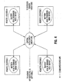
- FIG. 5 A more sophisticated type of network is depicted in Figure 5 which comprises a plurality of individual battery health management installations and/or one or more application specific networks. All of the data collected at the individual installations or sites on this network are collated at a master control center which is equipped to manage battery maintenance of individual sites or systems by providing routine monitoring, and/or diagnostic assistance.
- the master control center may be staffed with personnel who are well acquainted with battery systems and maintenance and who are able to analyse problems as reflected by the incoming data, and who can further provide and implement constructive and remedial advice.
- a battery health management device shown as sites in the networks depicted in Figures 4 and 5 may use an inserted connection circuit, shown in Figure 6, in place of the bridged connection circuit shown in Figures 1 and 2.
- An inserted connection circuit isolates one of the multiple modules in the battery pack (typically nine or eleven modules) by taking the cell out of the trickle/float charge circuit and then performing a discharge of the battery module which drains the energy of the module into variable discharge means such as a fixed resistance heater or similar device at the normal rated load capacity for that module.
- the PLC then records which module is being discharged, and how long it takes to discharge to a pre-programmed cut-off voltage. This information is then used to calculate how much energy the module was able to deliver under actual loaded conditions, thereby providing a real measure of its useful capacity.
- the information on module capacity is provided by way of a liquid crystal display, or similar means, and is given in watt-hours, ampere-hours; % of "as new" or the time to failure under load in minutes, whichever is required by the end user.
- a liquid crystal display or similar means
- % of "as new” or the time to failure under load in minutes whichever is required by the end user.
- batteries B1, B2 and B3 operate a charge/load circuit V.
- Isolation relays or contacts A and B connect an individual module to a monitor circuit, while contact C closes the gap in the battery created by the removal of the module.
- relay contact C When relay contact C is closed, the open circuit formed by the removal of the battery module is closed, thereby allowing current to flow through the charge/ load circuit.
- isolation relays A, B When isolation relays A, B are closed, an individual battery module can be isolated and connected to the monitor circuit. The monitor circuit discharges the isolated battery module and charges it as required using feedback provided by the current sensor and the preset voltage limits.
- the battery voltage would normally be (Vc * N-1) where Vc is the nominal module voltage and N is the number of modules in the battery.
- Vc the nominal module voltage
- N the number of modules in the battery.
- the module to be measured is accordingly isolated from the other modules comprising the battery pack by the selective engagement of isolation relays.
- the module is then discharged, its capacity is measured by the PLC as a function of the discharge load, and it is then recharged.
- the isolated module is temporarily unable to contribute to the output of the battery.
- the procedure is sequentially repeated, at selectable times, for the remaining modules which comprise the battery pack.
- an identical module to the battery modules in the battery pack can be added to the battery pack; for example, making a 9 module battery pack into a 10 module battery pack.
- the module battery charger will be powered from the battery pack.
- the invention can assess the state of health of the reduced capacity module and electrically isolate it from the rest of the battery pack, until such time as the rest of the pack has a poorer performing module than the isolated, reduced capacity module.
Abstract
Description
- The present invention relates to a system and method for the management of a battery pack used as a power back-up for an A.C. power source. The invention has particular application to distributed telecommunication systems and enables the useful capacity and health of a back-up battery power source of one or more of the links in the telecom system to be monitored, assessed and managed from a remote location.
- The invention may be used in conjunction with any device or network of devices which is battery-powered, or which uses a battery pack as an alternative or back-up power source, such as telecommunication relay sites, fibre optic sites, computers; telecommunication or station batteries; telephone switching facilities and portable test equipment.
- Other potential applications include railway crossing and switch systems; mobile electronic equipment battery packs used in cellular telephones, computers, camcorders or electric vehicles.
- There is presently no fully reliable and accurate means for determining the useful capacity of batteries, e.g. those used as a back up for a primary AC power source for an instrument or device which is situated at a remote location. In the event of an AC power failure, it is essential that the DC battery back-up power operate efficiently and at the required capacity. To date, there has been no practical method to load test a back-up battery at a remote site. Conventional devices measure voltage, impedance, electrolyte specific gravity or other battery characteristics, but do not provide the user with direct information concerning the length of time the battery will operate under load.
- Regarding the prior art, one of these is US Patent 4,707,795, issued to Alber at al. Alber et al provides a battery and monitoring system specifically designated to continuously monitor overall battery voltage, conditions of individual cells or cell groups such as voltage, current and temperature as well as individual cell or cell group failures. This system also is designed continuously monitor conduction path failures and other conditions. The system is a portable or permanently installed unit having connectable thereto a programming/display/printer terminal which enables the programming of the monitor with various failure conditions as desired. This terminal also enables the printing of a permanent record of any testing procedure. Furthermore, portable load units can be interconnected with the monitor and the battery or batteries which are currently being tested and monitored so as to enable the testing and/or monitoring of such battery or batteries under controlled load conditions.
- Another piece of prior art is US Patent 5,153,496 issued to LaForge. This patent discloses a cell monitoring and control circuit for a multicell battery. The circuit comprises a cell access switch coupled to the cells of the battery for electronically accessing individual cells of the battery. The circuit also includes a monitoring and control circuit coupled to the cell access switch for electronic communication with the cells. The circuit is coupled to the battery for providing electric power and constitutes an insignificant current drain on the battery. The circuit senses the voltage state of each cell and controls the charging of each cell and provides End-of-Discharge and End-of-Charge signals.
- Another piece of prior art is US Patent 5,543,245 issued to Andrieu et al. This patent discloses a system for monitoring aging of a battery comprising a plurality of cells connected in series and able to be fully discharged. The system comprises a plurality or dischargers which discharge respective ones of the previously charged cells to an end of discharge value. The quantity of electricity supplied by at least one discharged cell is processed to detect excessive aging of the battery. Excessive aging of the battery results in a residual capacity which is less than a fraction of the nominal capacity of the battery.
- However, none of the above-discussed prior art documents teaches to measure the discharge current and/or the charge current of the battery cell or module, for example for calculating the useful capacity of the respective cell or module. This can result in highly damaging conditions in the discharged cell or module, and overcharging the other cells or modules in the battery, adversely affecting the cell or module life.
- The present invention obviates and mitigates the disadvantages inherent in the prior art by providing a system according to
claim 1 as well as a method according to claim 10 for directly assessing the useful capacity of a back-up battery, even where the battery is located at a remote site and without compromising the ability of the back-up battery to operate should there be an AC power failure during the battery testing. - This objective is achieved by performing a sequential, individual assessment of each module which comprises a battery pack, wherein the provision of current measurement means for measuring a discharge current and/or a charge current of the battery module(s) enables the calculating of data with respect to the useful capacity of the battery module(s) based on the current of the battery module(s). Where used in this specification, the term "module" means one or more electrochemical cells.
- A further advantage of the present invention arises from its capability to rejuvenate or boost the health of the battery module of certain chemistries, e.g. valve regulated lead acid (VRLA) or nickel/cadmium. The discharge/charge sequence which is carried out in order to assess and monitor the useful capacity of the module, also serves to better cycle the module.
- The method according to the present invention enables managing the back-up, battery power source of the distributed communications systems of the telecommunications industry. The invention enables individual telecom sites with fibre optic or radio equipment powered by systems containing back-up batteries to be operated with improved reliability and economy. The invention provides smart charging at the cell or module level, thus ensuring that the back-up battery pack always receives optimum charging. The invention further provides a continuously updated battery pack capacity based on cell or module discharge tests so that the individual sites on the telecom system are provided with a real time method of back-up battery network management. This network battery management system provides the user with information to optimize the efficiency and operability of the telecom system, in case of AC power failure, particularly if there is a widespread or prolonged AC power outage.
- In one aspect (cf. claim 1), the invention provides a system
- for directly assessing the useful capacity of at least one battery module in a battery pack, and/or
- for cycling battery modules in a battery pack while the battery pack remains in service, and/or
- for battery health management of, in particular remotely situated back up, battery packs, the system comprising:
- a monitor circuit being operatively connected to a programmable logic controller and to one or more battery modules in the battery pack, the monitor circuit comprising
- -- battery module charging means,
- -- discharge load means, in particular discharging means for discharging the battery module, and
- -- at least one current measurement means for measuring a discharge current and/or a charge current of the at least one battery module;
- the programmable logic controller for calculating the useful capacity of the battery module based on the current of the at least one battery module; and
- a plurality of relays being controlled by the programmable logic controller and being connected between the monitor circuit and the battery pack, in particular being coupled between the battery module charging means, the discharge load means, and the battery modules,
the programmable logic controller - being designed for controlling the battery module charging means and the discharge load means and
- selectively, and in particular sequentially, opening and closing the plurality of relays, which connect with the battery module charging means and the discharge load means,
- -- to couple at least one battery module in the battery pack to the battery module charging means or to the discharging means and/or
- -- to alternatively define a discharge circuit which enables one of the modules to be discharged by the discharge load means, in particular under a predefined load, and/or to be recharged by said battery module charging means.
- Preferably, the programmable logic controller comprises, or is operatively connected to at least one module voltage reader;
battery pack current reader and module current reader; a switch controller to control said isolation relays; a controller for said variable discharge load means and said single module battery charger (charger/discharger controller). - In an additional aspect (cf. claim 10), the invention provides a method of sequentially assessing the operating capacity or useful capacity of a plurality of battery modules which define a battery pack, the method comprising the steps of:
- providing a programmable logic controller including a controller to control the opening and closing of relays;
- selecting one of said modules for assessment;
- connecting said selected module to a variable discharge load means by closing said relays which connect said module to said variable discharge load means;
- measuring current parameters which define the useful capacity of said module, while said module is under load;
- determining whether said useful capacity meets a predefined threshold for useful capacity;
- disconnecting said selected module from said variable discharge load means by opening said relays and either
- (a) connecting said selected module to a battery module charging means for recharging where said useful capacity meets said predefined threshold or
- (b) generating a signal where said useful capacity does not meet said predefined threshold;
wherein the coordination of all of the above steps is accomplished by the use of said programmable logic controller operatively comprising, in combination,
- at least one voltage reader;
- at least one battery current reader; and
- at least one module current reader.
- Preferably, the useful capacity is enhanced and/or the rate of capacity loss of the battery packs is reduced during service by using an optimal recharge method on the battery modules which comprise said battery pack while said battery pack remains in service; in particular, the plurality of different recharge methods can be chosen from the group comprising:
- a) constant voltage;
- b) constant current;
- c) constant power;
- d) fast charge;
- e) pulse charging.
-
- Figure 1 is a schematic drawing of a preferred embodiment of the invention, depicting a bridged connection circuit with three modules;
- Figure 2 is a schematic drawing of a further preferred embodiment of the invention, depicting a bridged connection circuit with "n" modules;
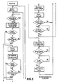
- Figure 3 is a flowchart, schematically depicting operation of the present invention;
- Figure 4 is a schematic representation of the network management system, being a further embodiment of the invention
- Figure 5 is a schematic representation of an enhanced battery management network, being a further embodiment of the invention
- Figure 6 is a schematic drawing of an optional inserted connection circuit
- The device of the present invention comprises a programmable logic controller (PLC) or computer, coupled to a plurality of multi-pole contactors, relays or solid state switching devices.
- The device of the present invention may be used in conjunction with rechargeable batteries of various chemical composition(s). Some are sealed, others are flooded while others are valve-regulated batteries. The typical chemistry of the batteries is nickel/cadmium or lead-acid. The threshold voltage is established having regard to the chemistry of the module.
- The invention makes use of a bridged connection circuit, which uses the principle of Kirchoff's law. Such an approach means that the module which is being assessed need not be isolated from the other modules comprising the battery pack. Figures 1 and 2 schematically represent a bridged connection. A bridged circuit ensures that the electrical integrity of the battery pack does not have to be broken in order to assess a single module. Using the algorithm outlined in Figure 3, the capacity of each module is sequentially calculated. The computer controls the opening and closing of isolation relays, the variable discharge load, as well as the module battery charger. Further the computer senses the following: battery pack string current and voltage, selected module charge/discharge current, selected module voltage, ambient temperature, and battery pack and/or module temperatures.
- In Figure 2, the battery pack is shown as operatively connected to a circuit comprising a load and a battery charger which represents the primary power source and load for which the battery pack is intended to provide back up. In order for the operative capacity of the back-up battery pack to be accurately measured, an allowance must be made for the current which flows from the primary power source into the battery pack. Use of Kirchoff's law, where +/- ic = +/- ip + +/- im where +/- is positive for charge and negative for discharge, ic is module current, ip is current of the primary power circuit, and im is the current of the monitor device, enables the PLC to accurately and selectively measure the operative capacity of a given module within the battery pack without isolating or disengaging the module from the other modules which comprise the battery pack.
- In operation, the controller selectively controls and coordinates the opening and closing of the switches which connect the battery charger and the variable discharge load. Where it is desired to measure the capacity of module or
cell 1, isolation relays A1 and B1 are closed by command of the PLC, which then closes the relays which connect the variable discharge load with the battery. The discharge circuit which is thus created enables module orcell 1 to be discharged across the variable discharge load. Module current is measured by a reader within the circuit and fed back to the PLC. The PLC then causes the relays connecting the variable discharge load to the battery to open, and then closes the relays which connect the battery charger with the battery, thereby defining a charging circuit which rechargesmodule 1 up to a threshold level which is consistent with the useful capacity of the other modules within the string. The procedure is then sequentially repeated for the remainingmodules - The programmable logic controller comprises, or is connected to at least one module voltage reader; at least one battery pack current reader and module current reader; a switch controller to control the isolation relays; a controller for said variable discharge load means and said single module battery charger (charger/discharger controller).
- Both the variable discharge load and battery charger output are adjusted according to the ambient battery and module temperature present to prevent battery damage. As well, the computer calculates the a-h (ampere-hour) capacity of each battery cell by integrating the discharge current over the time taken to reach the cut-off voltage threshold, or the energy capacity by the above integration of current times voltage over discharge time in hours. An alternative to using computer control of the variable discharge load and battery charger is direct control using linear circuits.
- The means used to discharge the module may be a use specific variable discharge profile, constant current, constant resistance, or constant power. The method chosen will depend on the battery technology and the normal usage. To implement these methods, a variable resistor or the like is typically used.
- The battery charger used to recharge the module under scrutiny may operate with a variety of algorithms including constant voltage/current, constant power and fast charge methods, including pulse charging.
- In another preferred embodiment, relays A, B and C shown in Figures 2 and 3 may be replaced with solid state switches. However, solid state devices have the following characteristics which affect their suitability as replacements for relays:
- 1) They tend to have a voltage drop when conducting current. In the inserted connection embodiment, the battery voltage under load would be reduced somewhat (a fraction of a volt). In the case of the bridged connection, this problem could be reduced by sensing battery voltages at the connection to the invention;
- 2) Usually, two such solid state devices are needed for conducting in two directions. This increases the cost and complexity of the design;
- 3) Inputs are not isolated from outputs. This is somewhat problematic, since the monitor circuit needs to connect to points up and down the chain of modules making up the battery. If the battery voltage exceeds 30 volts, optical isolation is needed which further complicates the design.
- Because of the problems outlined above, the use of solid state switches as replacements for relays A, B and C would be determined on a case by case basis. The most likely applications would be for batteries having voltages below 30 volts or with currents below a few amperes, or where the battery power levels are not much larger than the relay drive requirements or where the use of electromechanical relays is undesirable for other reasons.
- The invention works as an integral part of the battery and is designed to continue to operate in the event of an AC power failure, and is able to provide a full load current to substitute for a partially discharged module. This ensures that the useful capacity of the battery pack is available and that the module is protected from reverse-voltage damage.
- So that no capacity is lost in the unlikely event of the module battery charger failing when the isolated battery is discharged, extra capacity is provided in the form of an external module. This module will normally be float charged by the invention. When the battery charger fails during a discharge cycle, the external module or battery will be used to power the battery charger.
- The device of the present invention may further comprise an alarm circuit which conveys an audible or visible warning signal that the capacity of the battery pack has fallen below useful level, which is particularly important where the battery pack is being used as a back-up power source. This provides the: option of replacing individual batteries from the battery instead of the whole pack, thereby providing a substantial increase in battery pack life and a resulting decrease in battery cost to the user.
As depicted by Figure 4, a plurality of the devices of the present invention may be networked to permit the gathering of data required for the effective management of systems with multiple battery installations. The data collected from the network is collated in one central data center. This eases the problem of handling a large amount of data, enables the analysis of standby power in large, complex systems, which facilitates the making of rapid, well-informed decisions. - The embodiment shown in Figure 4 is a network of a plurality battery health management devices (shown in Figures 1 or 2 herein) installed in conjunction with the battery back up power sources for multiple, remote installations at sites on a telecommunications or other similar network or system. The remote battery health management devices are linked by multiple communications or sub-networks to one or more instations. The instation is equipped with suitable software to enable the instation to log data from the remote installations, generates alarms, produce statistics, group data in tables for comparison, plot trends, extrapolate data generate reports and assist in record keeping.
- The network shown in Figure 4 is application specific and focuses on assisting in the routine health management (including monitoring or power outages) of a remote battery, such as remote cellular site. Because of the emphasis on routine maintenance, the instation presents information such as battery back time remaining, alarms, maintenance records, site down time and power outages records. The system is equipped with extensive database facilities that are used for trending or to provide historical evidence of battery system status.
- A more sophisticated type of network is depicted in Figure 5 which comprises a plurality of individual battery health management installations and/or one or more application specific networks. All of the data collected at the individual installations or sites on this network are collated at a master control center which is equipped to manage battery maintenance of individual sites or systems by providing routine monitoring, and/or diagnostic assistance. The master control center may be staffed with personnel who are well acquainted with battery systems and maintenance and who are able to analyse problems as reflected by the incoming data, and who can further provide and implement constructive and remedial advice.
- Optionally, a battery health management device shown as sites in the networks depicted in Figures 4 and 5 may use an inserted connection circuit, shown in Figure 6, in place of the bridged connection circuit shown in Figures 1 and 2.
- An inserted connection circuit isolates one of the multiple modules in the battery pack (typically nine or eleven modules) by taking the cell out of the trickle/float charge circuit and then performing a discharge of the battery module which drains the energy of the module into variable discharge means such as a fixed resistance heater or similar device at the normal rated load capacity for that module. The PLC then records which module is being discharged, and how long it takes to discharge to a pre-programmed cut-off voltage. This information is then used to calculate how much energy the module was able to deliver under actual loaded conditions, thereby providing a real measure of its useful capacity. The information on module capacity is provided by way of a liquid crystal display, or similar means, and is given in watt-hours, ampere-hours; % of "as new" or the time to failure under load in minutes, whichever is required by the end user. When the measured capacity falls below a predefined threshold an alarm will be triggered, signalling the need for battery or module replacement. The battery module charger will be engaged to recharge the discharged module.
- In the inserted connection circuit shown in Figure 6, batteries B1, B2 and B3 operate a charge/load circuit V. Isolation relays or contacts A and B connect an individual module to a monitor circuit, while contact C closes the gap in the battery created by the removal of the module. When relay contact C is closed, the open circuit formed by the removal of the battery module is closed, thereby allowing current to flow through the charge/ load circuit. When isolation relays A, B are closed, an individual battery module can be isolated and connected to the monitor circuit. The monitor circuit discharges the isolated battery module and charges it as required using feedback provided by the current sensor and the preset voltage limits.
- In the event of an AC mains failure, the relays must continue to operate, otherwise a discharged module would be reintroduced into the battery pack, reducing the useful capacity of the battery pack.
- The battery voltage would normally be (Vc * N-1) where Vc is the nominal module voltage and N is the number of modules in the battery. As the monitor circuit moves from one module to the next, it causes a disruption in the battery pack voltage. The battery pack momentarily goes open-circuit, then the voltage Jumps to Vc* N, then the battery pack goes open-circuit again, then finally the voltage returns to (Vc * N-1).
- The module to be measured is accordingly isolated from the other modules comprising the battery pack by the selective engagement of isolation relays. The module is then discharged, its capacity is measured by the PLC as a function of the discharge load, and it is then recharged. The isolated module is temporarily unable to contribute to the output of the battery. The procedure is sequentially repeated, at selectable times, for the remaining modules which comprise the battery pack.
- Only one battery module at a time is discharged so that the system is never more than 1/9 or 11% short of its maximum ampere-hour or watt-hour energy capacity (in the case of a nine cell battery pack). In the event of an AC power outage (i.e. a situation where the DC battery pack is engaged), when one of the modules is not fully charged, this module is kept out of the circuit by the use of isolation relays.
- As an alternative to this method, an identical module to the battery modules in the battery pack can be added to the battery pack; for example, making a 9 module battery pack into a 10 module battery pack. In this case, the module battery charger will be powered from the battery pack.
- In the event that there is a battery module with less useful capacity than the other modules in the pack, the invention can assess the state of health of the reduced capacity module and electrically isolate it from the rest of the battery pack, until such time as the rest of the pack has a poorer performing module than the isolated, reduced capacity module.
Claims (16)
- A system- for directly assessing the useful capacity of at least one battery module in a battery pack, and/or- for cycling battery modules in a battery pack while the battery pack remains in service, and/or- for battery health management of, in particular remotely situated back up, battery packs, the system comprising:- a monitor circuit being operatively connected to a programmable logic controller and to one or more battery modules in the battery pack, the monitor circuit comprising-- battery module charging means,-- discharge load means, in particular discharging means for discharging the battery module, and-- at least one current measurement means for measuring a discharge current and/or a charge current of the at least one battery module;- the programmable logic controller for calculating data with respect to the useful capacity of the battery module based on the current of the at least one battery module; and- a plurality of relays being controlled by the programmable logic controller and being connected between the monitor circuit and the battery pack, in particular being coupled between the battery module charging means, the discharge load means, and the battery modules,
the programmable logic controller- being designed for controlling the battery module charging means and the discharge load means and- selectively, and in particular sequentially, opening and closing the plurality of relays, which connect with the battery module charging means and the discharge load means,-- to couple at least one battery module in the battery pack to the battery module charging means or to the discharging means and/or-- to alternatively define a discharge circuit which enables one of the modules to be discharged by the discharge load means and to be recharged by said battery module charging means. - The system according to claim 1, wherein- said programmable logic controller is connected by a communications link to a data center which collates and processes data transmitted by said programmable logic controller, and- data with respect to the useful capacity of the battery module is calculated by said programmable logic controller and is transmitted to said data center.
- The system according to claim 1 or 2, further comprising means for recording of said data calculated by said programmable logic controller.
- The system according to at least one of claims 1 to 3, wherein said relays are selected from the group consisting of multi-pole relays, contactors or solid state switching devices.
- The system according to at least one of claims 1 to 4, wherein the discharge load means for discharging the at least one battery module further includes means for discharging the at least one battery module under a predefined load.
- The system according to at least one of claims 1 to 5, wherein the discharge load means for discharging the at least one battery module further includes means for variably discharging the at least one battery module.
- The system according to at least one of claims 1 to 6, wherein the programmable logic controller includes:- a switch controller to control the plurality of relays;- a controller for the discharge load means; and- a controller for the battery module charging means.
- The system according to at least one of claims 1 to 7, wherein the data center is a master control center which provides a plurality of services including routine monitoring and diagnostic assistance.
- The system according to at least one of claims 1 to 8, characterized by enhancing the useful capacity and/or reducing the rate of capacity loss of the battery pack during service by using an optimal recharge method on the battery module which comprises said battery pack while said battery pack remains in service, wherein the plurality of different recharge methods are chosen from the group comprising:a) constant voltage;b) constant current;c) constant power;d) fast charge;e) pulse charging.
- A method of sequentially assessing the useful capacity of a plurality of battery modules which define a battery pack, the method comprising the steps of:- providing a programmable logic controller including a controller to control the opening and closing of relays;- selecting one of said modules for assessment;- connecting said selected module to a variable discharge load means by closing said relays which connect said module to said variable discharge load means;- measuring current parameters which define the useful capacity of said module, while said module is under load;- determining whether said useful capacity meets a predefined threshold for useful capacity;- disconnecting said selected module from said variable discharge load means by opening said relays and
either recharging said selected module by connecting said selected module to a battery module charging means where said useful capacity meets said predefined threshold
or generating a signal where said useful capacity does not meet said predefined threshold;
wherein- the above steps are coordinated by said programmable logic controller operatively comprising, in combination,-- at least one voltage reader;-- at least one battery current reader; and-- at least one module current reader. - The method according to claim 10, wherein the discharge load means discharges the selected module under a predefined ioad.
- The method according to claim 10 or 11, wherein the discharge load means discharges the selected module under variable loads.
- The method according to at least one of claims 10 to 12, further including recording capacity data regarding the useful capacity of the selected module.
- The method according to at least one of claims 10 to 13, further including determining a capacity of other modules in the battery pack from recorded capacity data of other modules in the battery pack and recharging the selected module by connecting the selected module to the battery module charging means, the selected module being recharged to a recharge level consistent with the capacity of other modules in the battery pack.
- The method according to at least one of claims 10 to 14, wherein the discharging means discharges the at least one battery module under a predefined load.
- The method according to at least one of claims 10 to 15, wherein the discharging means discharges the at least one battery module under variable loads.
Applications Claiming Priority (5)
| Application Number | Priority Date | Filing Date | Title |
|---|---|---|---|
| US887844 | 1997-07-03 | ||
| US08/887,844 US6239579B1 (en) | 1996-07-05 | 1997-07-03 | Device for managing battery packs by selectively monitoring and assessing the operative capacity of the battery modules in the pack |
| CA002209817A CA2209817C (en) | 1996-07-05 | 1997-07-04 | Device for managing battery packs by monitoring and assessing the operating capacity of the battery modules in the pack |
| CA2209817 | 1997-07-04 | ||
| PCT/CA1998/000650 WO1999001918A2 (en) | 1997-07-03 | 1998-07-03 | Device and system for management of battery back up power source |
Publications (2)
| Publication Number | Publication Date |
|---|---|
| EP0992100A2 EP0992100A2 (en) | 2000-04-12 |
| EP0992100B1 true EP0992100B1 (en) | 2007-04-25 |
Family
ID=25679471
Family Applications (1)
| Application Number | Title | Priority Date | Filing Date |
|---|---|---|---|
| EP98931856A Expired - Lifetime EP0992100B1 (en) | 1997-07-03 | 1998-07-03 | System and method for management of battery back up power source |
Country Status (5)
| Country | Link |
|---|---|
| EP (1) | EP0992100B1 (en) |
| AT (1) | ATE360909T1 (en) |
| AU (1) | AU8202298A (en) |
| DE (1) | DE69837661T2 (en) |
| WO (1) | WO1999001918A2 (en) |
Cited By (5)
| Publication number | Priority date | Publication date | Assignee | Title |
|---|---|---|---|---|
| US7711814B1 (en) | 2004-12-13 | 2010-05-04 | American Power Conversion Corporation | Method and system for remote monitoring of a power supply device with user registration capability |
| US7958170B2 (en) | 2002-05-03 | 2011-06-07 | American Power Conversion Corporation | Method and apparatus for collecting and displaying data associated with network devices |
| US8005944B2 (en) | 1999-10-27 | 2011-08-23 | American Power Conversion Corporation | Method and system for monitoring computer networks and equipment |
| US8145748B2 (en) | 2004-12-13 | 2012-03-27 | American Power Conversion Corporation | Remote monitoring system |
| US11215679B2 (en) | 2016-09-27 | 2022-01-04 | Huawei Technologies Co., Ltd. | Method and apparatus for detecting micro short circuit of battery |
Families Citing this family (33)
| Publication number | Priority date | Publication date | Assignee | Title |
|---|---|---|---|---|
| GB9820271D0 (en) * | 1998-09-17 | 1998-11-11 | Simoco Int Ltd | A method of and apparatus for monitoring the condition of batteries used by a mobile radio telecommunications fleet |
| JP3495636B2 (en) * | 1999-03-25 | 2004-02-09 | 株式会社マキタ | Charging device |
| US7330886B2 (en) | 1999-10-27 | 2008-02-12 | American Power Conversion Corporation | Network appliance management |
| FR2800525B1 (en) * | 1999-11-02 | 2001-12-21 | Accunord | DEVICE FOR MONITORING THE CONDITION OF THE BATTERY ACCUMULATORS |
| GB2359426A (en) * | 2000-02-18 | 2001-08-22 | Delta Impact Ltd | Battery back-up with deep discharge cycling |
| US8271626B2 (en) | 2001-01-26 | 2012-09-18 | American Power Conversion Corporation | Methods for displaying physical network topology and environmental status by location, organization, or responsible party |
| GB2413224B (en) | 2001-05-14 | 2005-12-07 | Eaton Power Quality Ltd | Battery charge management |
| TWI241762B (en) * | 2001-09-03 | 2005-10-11 | Gpe Internat Ltd | An intelligent fast battery charger |
| US7579842B2 (en) | 2002-09-26 | 2009-08-25 | Eaton Power Quality Company | Battery management apparatus |
| US7148796B2 (en) | 2003-04-14 | 2006-12-12 | American Power Conversion Corporation | Environmental monitoring device |
| US8566292B2 (en) | 2003-04-14 | 2013-10-22 | Schneider Electric It Corporation | Method and system for journaling and accessing sensor and configuration data |
| US7196494B2 (en) | 2003-10-17 | 2007-03-27 | Xantrex International | Method and apparatus for charging batteries in a system of batteries |
| US7627651B2 (en) | 2003-10-27 | 2009-12-01 | American Power Conversion Corporation | System and method for network device communication |
| US20050127874A1 (en) * | 2003-12-12 | 2005-06-16 | Myoungho Lim | Method and apparatus for multiple battery cell management |
| EP1641099A1 (en) | 2004-09-24 | 2006-03-29 | Conception et Développement Michelin S.A. | Detachable charge control circuit for balancing the voltage of supercapacitors connected in series |
| KR100740107B1 (en) * | 2005-09-08 | 2007-07-16 | 삼성에스디아이 주식회사 | Control signal generation circuit and battery management system using the same |
| US7723957B2 (en) | 2005-11-30 | 2010-05-25 | Lg Chem, Ltd. | System, method, and article of manufacture for determining an estimated battery parameter vector |
| CN101755495B (en) | 2007-05-15 | 2013-10-16 | 美国能量变换公司 | Methods and systems for managing facility power and cooling |
| TWM332909U (en) * | 2007-11-30 | 2008-05-21 | Lifebatt Production Inc | Far-end monitoring system for a battery module of an electromotive vehicle |
| US8598845B2 (en) * | 2009-04-20 | 2013-12-03 | Valence Technology, Inc. | Battery chargers, electrical systems, and rechargeable battery charging methods |
| GB0915299D0 (en) * | 2009-09-03 | 2009-10-07 | Scott Nigel D | Watchman hybrid |
| US8547064B2 (en) * | 2010-01-14 | 2013-10-01 | Texas Instruments Incorporated | Battery cell tab monitor |
| DE102010021176A1 (en) | 2010-05-21 | 2011-11-24 | Metabowerke Gmbh | Arrangement for single cell measurement in a battery pack and a battery pack with such an arrangement |
| DE102011008934A1 (en) * | 2011-01-19 | 2012-07-19 | Bmz Batterien-Montage-Zentrum Gmbh | Management system for rechargeable battery used in mobile device e.g. mobile telephone, has components which are integrated on single chip which stores software for evaluating optimal charging or discharging current |
| US8990536B2 (en) | 2011-06-01 | 2015-03-24 | Schneider Electric It Corporation | Systems and methods for journaling and executing device control instructions |
| US9952103B2 (en) | 2011-12-22 | 2018-04-24 | Schneider Electric It Corporation | Analysis of effect of transient events on temperature in a data center |
| CN103234579A (en) * | 2013-03-29 | 2013-08-07 | 国家电网公司 | Data processing method for online detection of energy storage battery parameters |
| US9658290B2 (en) * | 2013-11-20 | 2017-05-23 | Life Safety Distribution Ag | System and method of battery life estimation |
| DE102014201363A1 (en) | 2014-01-27 | 2015-07-30 | Robert Bosch Gmbh | Method and circuit arrangement for determining the Coulomb efficiency of battery modules |
| DE102014201365A1 (en) | 2014-01-27 | 2015-07-30 | Robert Bosch Gmbh | Method and circuit arrangement for determining the Coulomb efficiency of battery modules |
| WO2015200912A1 (en) * | 2014-06-27 | 2015-12-30 | Icc-Nexergy, Inc. | Required available capacity indication for battery backup unit |
| SE540739C2 (en) * | 2016-06-02 | 2018-10-30 | Megger Sweden Ab | Device and method for loading a voltage source |
| CN117239881B (en) * | 2023-11-10 | 2024-03-15 | 深圳市立泰能源科技有限公司 | Marine battery pack redundancy overcharge protection management system and method |
Family Cites Families (6)
| Publication number | Priority date | Publication date | Assignee | Title |
|---|---|---|---|---|
| US4484140A (en) * | 1982-04-23 | 1984-11-20 | The United States Of America As Represented By The Secretary Of The Navy | Battery scanning system |
| US4707795A (en) * | 1983-03-14 | 1987-11-17 | Alber Engineering, Inc. | Battery testing and monitoring system |
| DE3821808C2 (en) * | 1988-06-28 | 1994-06-16 | Helmut Haendel & Partner Mesda | Method and device for automatically testing the batteries of an uninterruptible power supply system |
| US5153496A (en) * | 1990-09-27 | 1992-10-06 | Baxtrer International Inc. | Cell monitor and control unit for multicell battery |
| FR2702885B1 (en) * | 1993-03-15 | 1995-04-21 | Alcatel Converters | System for monitoring the aging of a battery and method implemented in such a system. |
| US5710503A (en) * | 1996-02-01 | 1998-01-20 | Aims Systems, Inc. | On-line battery monitoring system with defective cell detection capability |
-
1998
- 1998-07-03 AU AU82022/98A patent/AU8202298A/en not_active Abandoned
- 1998-07-03 DE DE69837661T patent/DE69837661T2/en not_active Expired - Lifetime
- 1998-07-03 WO PCT/CA1998/000650 patent/WO1999001918A2/en active IP Right Grant
- 1998-07-03 EP EP98931856A patent/EP0992100B1/en not_active Expired - Lifetime
- 1998-07-03 AT AT98931856T patent/ATE360909T1/en not_active IP Right Cessation
Non-Patent Citations (1)
| Title |
|---|
| None * |
Cited By (7)
| Publication number | Priority date | Publication date | Assignee | Title |
|---|---|---|---|---|
| US8005944B2 (en) | 1999-10-27 | 2011-08-23 | American Power Conversion Corporation | Method and system for monitoring computer networks and equipment |
| US7958170B2 (en) | 2002-05-03 | 2011-06-07 | American Power Conversion Corporation | Method and apparatus for collecting and displaying data associated with network devices |
| US8019798B2 (en) | 2002-05-03 | 2011-09-13 | American Power Conversion Corporation | Method and apparatus for collecting and displaying network device information |
| US8719319B2 (en) | 2002-05-03 | 2014-05-06 | Schneider Electric It Corporation | Method and apparatus for collecting and displaying network device information |
| US7711814B1 (en) | 2004-12-13 | 2010-05-04 | American Power Conversion Corporation | Method and system for remote monitoring of a power supply device with user registration capability |
| US8145748B2 (en) | 2004-12-13 | 2012-03-27 | American Power Conversion Corporation | Remote monitoring system |
| US11215679B2 (en) | 2016-09-27 | 2022-01-04 | Huawei Technologies Co., Ltd. | Method and apparatus for detecting micro short circuit of battery |
Also Published As
| Publication number | Publication date |
|---|---|
| AU8202298A (en) | 1999-01-25 |
| EP0992100A2 (en) | 2000-04-12 |
| WO1999001918A3 (en) | 1999-04-22 |
| DE69837661D1 (en) | 2007-06-06 |
| ATE360909T1 (en) | 2007-05-15 |
| WO1999001918A2 (en) | 1999-01-14 |
| DE69837661T2 (en) | 2007-12-27 |
Similar Documents
| Publication | Publication Date | Title |
|---|---|---|
| EP0992100B1 (en) | System and method for management of battery back up power source | |
| US6329792B1 (en) | Device and system for management of battery back up power source | |
| CA2209817C (en) | Device for managing battery packs by monitoring and assessing the operating capacity of the battery modules in the pack | |
| US6504344B1 (en) | Monitoring battery packs | |
| CN100514744C (en) | Battery pack | |
| EP1396065B1 (en) | Back-up power system | |
| US7728552B2 (en) | Battery management system and method | |
| US7567060B1 (en) | System and method for advanced power management | |
| US6133709A (en) | Signalling system | |
| CN101192758A (en) | Charger | |
| WO1999010854A1 (en) | Battery capacity monitoring system | |
| WO2016183076A1 (en) | System and method for monitoring a dc power system | |
| CN110116622A (en) | Battery system used for rail vehicle | |
| US8525485B2 (en) | System and method for applying pulsation energy to online battery backup systems | |
| JP5361594B2 (en) | Lithium ion secondary battery system and power supply method to management device | |
| EP2837082B1 (en) | Method and system for remote measurement of available capacity of the batteries in the telecommunications power system | |
| CN110165310A (en) | A kind of battery pack intelligence managing and control system | |
| CN111999663A (en) | Battery connecting wire breakage detection device | |
| JP4392176B2 (en) | Battery pack capacity test apparatus and battery pack capacity test method | |
| CA2317045C (en) | Device and system for management of battery back up power source | |
| CN111313493A (en) | Self-healing type direct-current power supply protection device | |
| US20050007071A1 (en) | Circuit arrangement for an autonomous power supply system, and a method for its operation | |
| CN117517947B (en) | Method and device for monitoring contact adhesion of high-voltage box relay | |
| CN212627218U (en) | Battery management circuit | |
| Desanti et al. | Decreasing owning costs of MV/LV substations backup batteries |
Legal Events
| Date | Code | Title | Description |
|---|---|---|---|
| PUAI | Public reference made under article 153(3) epc to a published international application that has entered the european phase |
Free format text: ORIGINAL CODE: 0009012 |
|
| 17P | Request for examination filed |
Effective date: 20000126 |
|
| AK | Designated contracting states |
Kind code of ref document: A2 Designated state(s): AT BE CH CY DE DK ES FI FR GB GR IE IT LI LU MC NL PT SE |
|
| 17Q | First examination report despatched |
Effective date: 20010723 |
|
| RAP1 | Party data changed (applicant data changed or rights of an application transferred) |
Owner name: ESTCO BATTERY MANAGEMENT, INC. |
|
| GRAP | Despatch of communication of intention to grant a patent |
Free format text: ORIGINAL CODE: EPIDOSNIGR1 |
|
| RTI1 | Title (correction) |
Free format text: SYSTEM AND METHOD FOR MANAGEMENT OF BATTERY BACK UP POWER SOURCE |
|
| GRAS | Grant fee paid |
Free format text: ORIGINAL CODE: EPIDOSNIGR3 |
|
| RAP1 | Party data changed (applicant data changed or rights of an application transferred) |
Owner name: R.V. HOLDINGS CORP. IN TRUST |
|
| 17Q | First examination report despatched |
Effective date: 20010723 |
|
| GRAA | (expected) grant |
Free format text: ORIGINAL CODE: 0009210 |
|
| AK | Designated contracting states |
Kind code of ref document: B1 Designated state(s): AT BE CH CY DE DK ES FI FR GB GR IE IT LI LU MC NL PT SE |
|
| PG25 | Lapsed in a contracting state [announced via postgrant information from national office to epo] |
Ref country code: LI Free format text: LAPSE BECAUSE OF FAILURE TO SUBMIT A TRANSLATION OF THE DESCRIPTION OR TO PAY THE FEE WITHIN THE PRESCRIBED TIME-LIMIT Effective date: 20070425 Ref country code: FI Free format text: LAPSE BECAUSE OF FAILURE TO SUBMIT A TRANSLATION OF THE DESCRIPTION OR TO PAY THE FEE WITHIN THE PRESCRIBED TIME-LIMIT Effective date: 20070425 Ref country code: CH Free format text: LAPSE BECAUSE OF FAILURE TO SUBMIT A TRANSLATION OF THE DESCRIPTION OR TO PAY THE FEE WITHIN THE PRESCRIBED TIME-LIMIT Effective date: 20070425 |
|
| REG | Reference to a national code |
Ref country code: GB Ref legal event code: FG4D |
|
| REG | Reference to a national code |
Ref country code: IE Ref legal event code: FG4D |
|
| REG | Reference to a national code |
Ref country code: CH Ref legal event code: EP |
|
| REF | Corresponds to: |
Ref document number: 69837661 Country of ref document: DE Date of ref document: 20070606 Kind code of ref document: P |
|
| PG25 | Lapsed in a contracting state [announced via postgrant information from national office to epo] |
Ref country code: SE Free format text: LAPSE BECAUSE OF FAILURE TO SUBMIT A TRANSLATION OF THE DESCRIPTION OR TO PAY THE FEE WITHIN THE PRESCRIBED TIME-LIMIT Effective date: 20070725 |
|
| PG25 | Lapsed in a contracting state [announced via postgrant information from national office to epo] |
Ref country code: ES Free format text: LAPSE BECAUSE OF FAILURE TO SUBMIT A TRANSLATION OF THE DESCRIPTION OR TO PAY THE FEE WITHIN THE PRESCRIBED TIME-LIMIT Effective date: 20070805 |
|
| PG25 | Lapsed in a contracting state [announced via postgrant information from national office to epo] |
Ref country code: PT Free format text: LAPSE BECAUSE OF FAILURE TO SUBMIT A TRANSLATION OF THE DESCRIPTION OR TO PAY THE FEE WITHIN THE PRESCRIBED TIME-LIMIT Effective date: 20070925 |
|
| ET | Fr: translation filed | ||
| REG | Reference to a national code |
Ref country code: CH Ref legal event code: PL |
|
| NLV1 | Nl: lapsed or annulled due to failure to fulfill the requirements of art. 29p and 29m of the patents act | ||
| PG25 | Lapsed in a contracting state [announced via postgrant information from national office to epo] |
Ref country code: AT Free format text: LAPSE BECAUSE OF FAILURE TO SUBMIT A TRANSLATION OF THE DESCRIPTION OR TO PAY THE FEE WITHIN THE PRESCRIBED TIME-LIMIT Effective date: 20070425 |
|
| PG25 | Lapsed in a contracting state [announced via postgrant information from national office to epo] |
Ref country code: BE Free format text: LAPSE BECAUSE OF FAILURE TO SUBMIT A TRANSLATION OF THE DESCRIPTION OR TO PAY THE FEE WITHIN THE PRESCRIBED TIME-LIMIT Effective date: 20070425 |
|
| PG25 | Lapsed in a contracting state [announced via postgrant information from national office to epo] |
Ref country code: NL Free format text: LAPSE BECAUSE OF FAILURE TO SUBMIT A TRANSLATION OF THE DESCRIPTION OR TO PAY THE FEE WITHIN THE PRESCRIBED TIME-LIMIT Effective date: 20070425 Ref country code: DK Free format text: LAPSE BECAUSE OF FAILURE TO SUBMIT A TRANSLATION OF THE DESCRIPTION OR TO PAY THE FEE WITHIN THE PRESCRIBED TIME-LIMIT Effective date: 20070425 |
|
| PLBE | No opposition filed within time limit |
Free format text: ORIGINAL CODE: 0009261 |
|
| STAA | Information on the status of an ep patent application or granted ep patent |
Free format text: STATUS: NO OPPOSITION FILED WITHIN TIME LIMIT |
|
| 26N | No opposition filed |
Effective date: 20080128 |
|
| PG25 | Lapsed in a contracting state [announced via postgrant information from national office to epo] |
Ref country code: MC Free format text: LAPSE BECAUSE OF NON-PAYMENT OF DUE FEES Effective date: 20070731 Ref country code: IT Free format text: LAPSE BECAUSE OF FAILURE TO SUBMIT A TRANSLATION OF THE DESCRIPTION OR TO PAY THE FEE WITHIN THE PRESCRIBED TIME-LIMIT Effective date: 20070425 Ref country code: GR Free format text: LAPSE BECAUSE OF FAILURE TO SUBMIT A TRANSLATION OF THE DESCRIPTION OR TO PAY THE FEE WITHIN THE PRESCRIBED TIME-LIMIT Effective date: 20070726 |
|
| PG25 | Lapsed in a contracting state [announced via postgrant information from national office to epo] |
Ref country code: IE Free format text: LAPSE BECAUSE OF NON-PAYMENT OF DUE FEES Effective date: 20070703 |
|
| PG25 | Lapsed in a contracting state [announced via postgrant information from national office to epo] |
Ref country code: CY Free format text: LAPSE BECAUSE OF FAILURE TO SUBMIT A TRANSLATION OF THE DESCRIPTION OR TO PAY THE FEE WITHIN THE PRESCRIBED TIME-LIMIT Effective date: 20070425 |
|
| PG25 | Lapsed in a contracting state [announced via postgrant information from national office to epo] |
Ref country code: LU Free format text: LAPSE BECAUSE OF NON-PAYMENT OF DUE FEES Effective date: 20070703 |
|
| PGFP | Annual fee paid to national office [announced via postgrant information from national office to epo] |
Ref country code: GB Payment date: 20140702 Year of fee payment: 17 Ref country code: FR Payment date: 20140630 Year of fee payment: 17 |
|
| GBPC | Gb: european patent ceased through non-payment of renewal fee |
Effective date: 20150703 |
|
| PG25 | Lapsed in a contracting state [announced via postgrant information from national office to epo] |
Ref country code: GB Free format text: LAPSE BECAUSE OF NON-PAYMENT OF DUE FEES Effective date: 20150703 |
|
| REG | Reference to a national code |
Ref country code: FR Ref legal event code: ST Effective date: 20160331 |
|
| PG25 | Lapsed in a contracting state [announced via postgrant information from national office to epo] |
Ref country code: FR Free format text: LAPSE BECAUSE OF NON-PAYMENT OF DUE FEES Effective date: 20150731 |
|
| PGFP | Annual fee paid to national office [announced via postgrant information from national office to epo] |
Ref country code: DE Payment date: 20170613 Year of fee payment: 20 |
|
| REG | Reference to a national code |
Ref country code: DE Ref legal event code: R071 Ref document number: 69837661 Country of ref document: DE |