EP0992662A2 - Throttle apparatus for an internal combustion engine - Google Patents
Throttle apparatus for an internal combustion engine Download PDFInfo
- Publication number
- EP0992662A2 EP0992662A2 EP99119135A EP99119135A EP0992662A2 EP 0992662 A2 EP0992662 A2 EP 0992662A2 EP 99119135 A EP99119135 A EP 99119135A EP 99119135 A EP99119135 A EP 99119135A EP 0992662 A2 EP0992662 A2 EP 0992662A2
- Authority
- EP
- European Patent Office
- Prior art keywords
- throttle valve
- throttle
- spring
- default
- opening degree
- Prior art date
- Legal status (The legal status is an assumption and is not a legal conclusion. Google has not performed a legal analysis and makes no representation as to the accuracy of the status listed.)
- Granted
Links
Images


Classifications
-
- F—MECHANICAL ENGINEERING; LIGHTING; HEATING; WEAPONS; BLASTING
- F02—COMBUSTION ENGINES; HOT-GAS OR COMBUSTION-PRODUCT ENGINE PLANTS
- F02D—CONTROLLING COMBUSTION ENGINES
- F02D9/00—Controlling engines by throttling air or fuel-and-air induction conduits or exhaust conduits
- F02D9/08—Throttle valves specially adapted therefor; Arrangements of such valves in conduits
- F02D9/10—Throttle valves specially adapted therefor; Arrangements of such valves in conduits having pivotally-mounted flaps
- F02D9/1065—Mechanical control linkage between an actuator and the flap, e.g. including levers, gears, springs, clutches, limit stops of the like
-
- F—MECHANICAL ENGINEERING; LIGHTING; HEATING; WEAPONS; BLASTING
- F02—COMBUSTION ENGINES; HOT-GAS OR COMBUSTION-PRODUCT ENGINE PLANTS
- F02D—CONTROLLING COMBUSTION ENGINES
- F02D11/00—Arrangements for, or adaptations to, non-automatic engine control initiation means, e.g. operator initiated
- F02D11/06—Arrangements for, or adaptations to, non-automatic engine control initiation means, e.g. operator initiated characterised by non-mechanical control linkages, e.g. fluid control linkages or by control linkages with power drive or assistance
- F02D11/10—Arrangements for, or adaptations to, non-automatic engine control initiation means, e.g. operator initiated characterised by non-mechanical control linkages, e.g. fluid control linkages or by control linkages with power drive or assistance of the electric type
-
- F—MECHANICAL ENGINEERING; LIGHTING; HEATING; WEAPONS; BLASTING
- F02—COMBUSTION ENGINES; HOT-GAS OR COMBUSTION-PRODUCT ENGINE PLANTS
- F02D—CONTROLLING COMBUSTION ENGINES
- F02D2200/00—Input parameters for engine control
- F02D2200/02—Input parameters for engine control the parameters being related to the engine
- F02D2200/04—Engine intake system parameters
- F02D2200/0404—Throttle position
-
- F—MECHANICAL ENGINEERING; LIGHTING; HEATING; WEAPONS; BLASTING
- F16—ENGINEERING ELEMENTS AND UNITS; GENERAL MEASURES FOR PRODUCING AND MAINTAINING EFFECTIVE FUNCTIONING OF MACHINES OR INSTALLATIONS; THERMAL INSULATION IN GENERAL
- F16N—LUBRICATING
- F16N15/00—Lubrication with substances other than oil or grease; Lubrication characterised by the use of particular lubricants in particular apparatus or conditions
Definitions
- the present invention relates to a throttle apparatus for an internal combustion engine and, more particularly, to an electronic control throttle device which controls opening and closing a throttle valve by driving an electric driven actuator based on a control signal.
- an initial opening degree (default opening degree) of the throttle valve in an off state of engine key is set to a position larger than its full close position.
- the full close position does not mean a position for completely choking the intake air passage.
- the full close position is defined by classifying into a mechanical full close position and an electrical full close position to be described below.
- the mechanical full close position means a minimum opening degree position of a throttle valve determined by a stopper, and the minimum opening degree is set at a position to slightly open the throttle valve from a position to completely choking the intake air passage in order to prevent the throttle valve from sticking.
- the electrical full close position means a minimum opening degree within a range of opening degrees used for control, and the minimum opening degree is set at an opening position slightly larger than the mechanical full close position in taking the mechanical full close position as the reference by controlling of driving the electric driven actuator (for instance, a position larger than the mechanical full close position by approximately 1° ).
- the electrical full close position (the minimum opening degree on the control purpose) does not always agree with an idling opening degree (an opening degree necessary for idling rotating speed control). The reason is that because the opening degree of the throttle valve is feedback controlled based on an idling rotating speed detected signal in order to keep the idling rotating speed to a target rotating speed, and thereby the opening degree can not be determined uniquely.
- a full open position there are a mechanical full open position determined by a stopper and an electrical full open position of a maximum opening degree on control.
- an electrical full close position meaning of the word includes the electrical full close position as well as the mechanical full close position.
- the throttle valve is controlled between the electrical full close position (the minimum opening degree on the control purpose) and the electrical full open position (the maximum opening degree on the control purpose). By doing so, a part of the throttle valve does not hit on the stoppers for determining the mechanical full close position and the mechanical full open position at controlling the throttle valve to the minimum and the maximum opening degrees. Therefore, mechanical fatigue, abrasion and damage of the stoppers and the gear members can be prevented and sticking of the throttle valve to the stopper can be prevented.
- a default opening degree (that is, the initial opening degree in an off state of engine key) is set to an opening degree of a position in which the throttle valve is further opened wider than that in the full close position (the mechanical full close position and the electrical full close position)(for example, a position larger than the mechanical full close position by 4 to 13° ).
- the default opening degree is set is that an air flow rate necessary for combustion of pre-warming-up operation at stating -up of the engine (cold starting-up) is secured without any auxiliary air passage (an air passage bypassing the throttle valve).
- the throttle valve is controlled so as to moved from the default opening degree toward the smaller opening degree.
- the lower limit is the electrical full close position.
- Another reason why the default opening degree is set is to cope with requirements for securing self-running (limp home) or for securing an intake air flow rate to prevent the engine operation from stopping even if the throttle control system is failed, for preventing the throttle valve from fixing to an inner surface of the throttle body with a viscous substance or ice.
- default opening degree setting mechanisms As conventional examples of default opening degree setting mechanisms, various kinds of default opening degree setting mechanisms are proposed in, for example, Japanese Patent Application Laid-Open No.63-150449, USP 4,947,815 and the corresponding patent of Japanese Patent Application Laid-Open No.2-500677, Japanese Patent Application Laid-Open No.62-82238 and the corresponding patent of USP 4,735,179 by the same applicant of the present invention, Japanese Patent Application Laid-Open No.10-89096, Japanese Patent Application Laid-Open No.10-131771 and so on.
- default opening degree setting mechanisms There are various types of default opening degree setting mechanisms.
- one type is that a default opening degree is secured by setting the relationship between forces of a returning spring for acting a force toward a closing direction of the throttle valve and an opposed spring (called as a default spring or an initial opening degree spring) for acting a force toward an opening direction of the throttle valve opposing against the force of the returning spring so that the force of the default spring is larger than the force of the returning spring at the default opening degree position and so that a free end of the default spring is stopped by a default stopper at the default opening degree position when the engine key is switched off (for example, Japanese Patent Application Laid-Open No.2-500677).
- a fixing side engaging element to be fixed to a throttle valve shaft (this engaging element may be constructed by a throttle lever, or a gear for transmitting motor power may be used instead of the engaging element) and a moving side engaging element (a linking lever) idly inserted onto the throttle valve shaft and rotatable relative to the throttle valve shaft are provided, and the moving side engaging element and the fixing side engaging element are linked together with a returning spring so as to attract each other, and a force is applied using a default spring onto the moving side engaging element in a direction of opening the throttle valve to engage and rotate the moving side engaging element and the fixing side engaging element (the throttle valve shaft) together opposing against the force of the default spring when the opening degree is within the range smaller than the default opening degree (smaller than the default stopper position), and to rotate only the fixing side engaging element and accordingly the throttle valve shaft opposing against the force of the returning spring and preventing movement of the moving side engaging element by the default stopper when the opening
- the moving side engaging element and the fixing side engaging element are linked together with the default spring so as to attract each other, and a force is applied using the returning spring onto the moving side engaging element in a direction of closing the throttle valve to engage and rotate the moving side engaging element and the fixing side engaging element (the throttle valve shaft) together opposing against the force of the returning spring when the opening degree is within the range larger than the default opening degree, and to rotate only the fixing side engaging element (the throttle valve shaft) opposing against the force of the default spring and preventing movement of the moving side engaging element by the default stopper when the opening degree is within the range smaller than the default opening degree.
- the electronic control throttle device can more accurately perform air flow rate control suitable for operation of an internal combustion engine than a mechanical throttle device in which an amount of stepping-in of the accelerator pedal is transmitted to a throttle valve shaft through an accelerator wire.
- the electronic control throttle device has the electric drive actuator and the default opening degree setting mechanism, number of the parts is increased and accordingly it is important how to make the throttle body small in size, light in weight and simple in structure and how to simplify the wiring (wire harness).
- the electronic control throttle device controls the idling rotating speed by controlling opening degree of the throttle valve, but has the following point to be improved.
- an opening degree larger than the mechanical full close position by a certain angle is secured at least as the minimum opening degree on the control purpose. Since a gap (sometime called as a shaft support gap) between the throttle valve shaft and a shaft inserting through hole provided in a wall of the throttle body which guides the throttle valve shaft to a bearing practically serves as a part of the intake air passage and the air flow rate (leak air flow rate) flowing through the shaft support gap can not be controlled, the minimum opening degree on the control purpose is set with taking it into consideration that the leak flow rate flows into the internal combustion engine.
- the throttle valve hits on the stopper at the mechanical full close position (the diagonally shaded area in FIG. 17 indicates a state that movement of the throttle valve is blocked by the full close stopper.), and over-current flows in the motor likely to cause an erroneous fail-safe diagnosis (an erroneous diagnosis judging of occurrence of failure in the motor from the over current) or decrease in the lifetime of the motor.
- An object of the present invention is to make an electronic control throttle device having an electric drive actuator, a gear mechanism, a default opening degree setting mechanism small in size, light in weight and simple in assembling and wire harness by solving the above-mentioned problems.
- Another object of the present invention is to improve reliability of the electronic control throttle device by preventing the throttle valve from hitting on the stopper even if such an overshoot as described above occurs in the throttle valve.
- the present invention is basically constructed as follows.
- a throttle device for an internal combustion engine includes an electric drive actuator and a default opening degree setting mechanism, wherein a gear case for containing a gear mechanism to transmit power of the electric drive actuator to a throttle valve shaft is arranged on an outer wall of a throttle body, and a returning spring for acting a spring force on the throttle valve in a closing direction and a spring (a default spring) for acting a spring force on the throttle valve in a direction toward a side of the default opening degree seeing from the full close position of the throttle valve have diameters different from each other, and both of the springs are held around a shaft of said throttle valve shaft and arranged between a gear attached to the throttle valve shaft in the gear mechanism and a wall portion of the throttle body.
- the returning spring and the default spring can be intensively arranged between the gear provided in the throttle shaft and the wall portion of the throttle body, and accordingly the part space can be rationalized.
- the returning spring and the default spring in such a feature that at least a part of the returning spring and a part of the default spring are overlapped with each other (one spring having a smaller diameter is inserted inside the other spring having a larger diameter), an arranging space in a longitudinal direction of the springs can be shortened, and accordingly this structure is useful in that the gear case and the whole throttle body can be made small in size, light in weight and simple in assembling.
- the present invention proposes a construction that the spring arranged outside out of the returning spring and the default spring (the spring having the larger diameter) is placed in being guided by an outer periphery of a bearing containing boss for the throttle valve shaft projecting inward of the gear case in a manner that one end of the spring having the larger diameter is fixed to the wall portion of the throttle body.
- the outer periphery of the bearing containing boss for the throttle valve shaft can be used for a space placing one spring out of the returning spring and the default spring. Accordingly, this structure is useful in that the parts can be more intensively arranged, and the throttle body can be made smaller in size and light in weight.
- a throttle body, a motor case containing a motor composing an electric drive actuator and a containing portion of a connector connecting by plugging to a motor terminal provided in an end plate of said motor are formed in a unit.
- a motor terminal extracting port for exposing the motor terminal to the containing portion of the connector is formed on a bottom portion of the motor case, and a guide for guiding the connector to the motor terminal extracting port when the connector is plugged to the motor terminal is formed on an inner wall surface of the containing portion of the connector.
- the connector can be easily connected to the motor terminal without difficulty of positioning the connector to the motor terminal because by containing the motor in the motor case the motor terminal can be seen in the containing portion of the connector (the terminal connector) through the terminal extracting port, and in this state the terminal connector is inserted from the terminal containing portion using the guide. Even if the motor terminal is, particularly, placed in a deep position of the connector containing portion and behind the other parts, the connector can be inserted by being guided by the above-mentioned guide without difficulty while being positioned.
- a motor case for containing a motor composing the electric drive actuator is integrated with a throttle body in a unit.
- a motor terminal extracting port is formed in a side of a bottom portion of the motor case, a containing space of a connector to be connected to the motor terminal being formed adjacent to the side of the bottom portion of said motor case, the containing space of the connector and a containing space for containing a throttle sensor provided at one end of a throttle valve shaft being formed in one room, a wire lead portion of the throttle sensor being arranged in being directed to the containing space of the motor terminal connector.
- the wires led from the terminal of the throttle sensor and the wires led from the motor terminal can be merged at adjacent positions in the beginning in the connector and throttle sensor containing space (one room), and accordingly these wires can be gathered without difficulty and can be extracted out of the throttle body. Therefore, this construction is useful to simplify the wiring work and the part assembling work.
- a motor case for containing a motor composing the electric drive actuator and a gear case for containing a gear mechanism to transmit power of the motor to a throttle valve shaft are integrated in a unit.
- a motor inserting port of the motor case is opened to the gear case, the motor being attached to the motor case by fastening a motor bracket to triangular point arranged screw holes provided a periphery of the motor inserting port with three screws in total, three sides forming a contour of the motor bracket being curved lines, a motor positioning portion fitting to the three curved lines of the motor bracket to position the motor being formed in the gear case.
- vibration of the motor can be suppressed more effectively than in a conventional one in which the motor bracket is fastened at two points with screws, and further accuracy of positioning the motor can be improved.
- An electronic control throttle device includes an electric drive actuator for opening and closing a throttle valve based on a signal controlling an intake air flow rate of the internal combustion engine.
- a gap (a shaft supporting gap) between a throttle valve shaft and a shaft inserting through hole for guiding the throttle valve shaft to a bearing provided in a wall portion of a throttle body is filled with an air leak preventing material, and a minimum opening degree on control purpose of the throttle valve is set to a value larger than an amount of overshoot of the throttle valve occurring when opening degree of the throttle valve is changed from a maximum opening degree on control purpose of the throttle valve to the minimum opening degree.
- the minimum opening degree on the control purpose of the throttle valve can be increased larger than in the conventional one by that amount.
- the minimum opening degree on the control purpose is set a value lager than the overshoot of the throttle valve when opening degree of the throttle valve is changed from the maximum opening degree on control purpose of the throttle valve to the minimum opening degree.
- the air leak preventing material for example, molybdenum disulfide
- the minimum opening degree on the control purpose can be set a value lager than the mechanical full close position by approximately 2° , the minimum opening degree on the control purpose can be increased higher by a value corresponding to the overshoot (for instance, approximately 1.5° ) when opening degree of the throttle valve is changed from the maximum opening degree on control purpose (the electrical full open position) to the minimum opening degree (the electrical full close position). Therefore, the stopper blocking element in the side of the throttle valve can be prevented from hitting on the stopper (the full close stopper) determining the mechanical full close position even if the overshoot occurs. Accordingly, even if the overshoot occurs, it is possible to prevent over current from flowing in the motor.
- the above-mentioned operation and effect are attained on the premises that the gap (the shaft supporting gap) between the throttle valve shaft and the shaft inserting through hole for guiding the throttle valve shaft to the bearing provided in the wall portion of the throttle body is filled with the air leak preventing material.
- the above-mentioned operation and effect can not be expected in a mechanical throttle device in which a stepping amount of an accelerator is transmitted to a throttle valve shaft through an accelerator wire even if the so-called shaft supporting gap is filled with the air leak preventing material.
- the reason is as follows.
- the idling opening degree in the mechanical throttle device is set to a position where a mechanical full closing stopper exists, and the mechanical throttle device is designed on the premises that the stopper blocking element controlling the throttle valve hits on the full close stopper during operation. Further, since the throttle valve is mechanically driven using the accelerator wire, there is no occurrence of overshoot nor occurrence of over current attendant on the overshoot differently from in the electronic control throttle device.
- the Japanese Patent Application Laid-Open No.62-17100 proposes a technology that in a mechanical throttle device, a dryable liquid lubricant (for example, molybdenum disulfide) is penetrated into an air passage formed between a throttle valve shaft and a shaft inserting through hole in a wall portion of the throttle valve assembly (the shaft supporting gap) and dried to fill the air passage with the lubricant solidified and fixed to the air passage.
- a dryable liquid lubricant for example, molybdenum disulfide
- an idling rotating speed of an engine is set in taking the amount of the air flowing through the so-called shaft supporting gap into consideration since the air flowing through the gap can not be controlled by the throttle valve, but the idling rotating speed is gradually decreased and finally the engine may be stopped because combustion products (combustion soot, viscous substance or the like) are gradually accumulated in the shaft supporting gap. Therefore, the setting of the idling rotating speed is performed by eliminating the gap in the beginning to eliminate the change in the idling air flow rate with time and by using a full close stopper (an idling adjust screw).
- the idling rotating speed control can be performed by controlling the throttle valve opening degree through feedback control (that is, the idling opening degree is not determined using the idling adjusting screw used in the mechanical throttle device). Therefore, even if combustion products are gradually accumulated in the shaft supporting gap of the throttle valve shaft, decrease in the air flow rate (decrease in the idling rotating speed) caused by the accumulation of the combustion products can be compensated by controlling the throttle valve opening degree. From this point of view, the above-mentioned problem specific to the mechanical throttle device (the problem of the decrease in idling rotating speed caused by accumulation of combustion products in the shaft supporting gap) does not occur in the electronic control throttle device. In other words, there are differences in problem to be solved and in object between the air leak preventing material applied to the shaft supporting gap in the electronic control throttle device and the air leak preventing material applied to the shaft supporting gap in the mechanical throttle device.
- an electromagnetic shield member of a wire used for driving control of the electric drive actuator is a woven shield composed of a tube-shaped member formed by weaving glass fiber and a woven thin metal wire member covering the tube-shaped member.
- a conventional electromagnetic shield member of this kind is formed by covering a tube made of silicon rubber with a shielding outer cover of woven thin metal wires.
- the electromagnetic shield member of the above-mentioned structure can substantially reduce its cost and can effectively shield electromagnetic wave compared to the conventional electromagnetic shield member.
- FIG. 1A is a schematic perspective view showing an electric drive mechanism of throttle valve and a default mechanism in the present embodiment
- FIG. 1B is an explanatory view equivalently expressing the above-mentioned mechanisms.
- a flow rate of air flowing in an intake air passage 1 is adjusted corresponding to an opening degree of a disk-shaped throttle valve 2.
- the throttle valve 2 is fixed to a throttle valve shaft 3.
- a final stage gear (referred to as a throttle gear) 43 of a gear mechanism (a reduction gear mechanism) 4 for transmitting power of a motor (an electric drive actuator) 5 to the throttle valve shaft 3 is attached.
- the gear mechanism 4 is composed of a pinion gear 41 attached to the motor 5 and an intermediate gear 42 in addition to the throttle gear 43.
- the intermediate gear 42 is composed of a large diameter gear 42a engaging with the pinion gear 41 and a small diameter gear 42b engaging with the throttle gear 43, and is rotatably inserted into a gear shaft 70 fixed to a wall surface of a throttle body 100.
- the motor 5 is driven corresponding to an accelerator signal in regard to a stepping amount of an accelerator pedal and a traction control signal, and the power of the motor is transmitted to the throttle valve shaft 3 through the gears 41, 42, 43.
- the throttle gear is a sectorial gear and fixed to the throttle valve shaft 3, and also serves as a fixed side engaging element, to be described later, in order to reduce number of parts, and has an engaging side 43a for engaging with an arm portion 62 of an engaging lever (a moving side engaging element) 6 to be described later.
- the engaging lever 6 is used for a default opening degree setting mechanism, and therefore, is hereinafter referred to as a default lever.
- the default lever 6 is idly inserted onto the throttle valve shaft 3 and rotatable relative to the throttle valve shaft, and is an engaging element in the moving side to the above-mentioned fixing side engaging element (gear) 43.
- the fixing side engaging element (gear) 43 and the moving side engaging element (the default lever) 6 are attracted to each other through a default spring 8 by connecting between a spring fastening portion (shown by a reference character 64 in FIG. 2) of the default lever 6 and a spring fastening portion 9 fixed to the throttle valve shaft 3 with the default spring 8.
- a returning spring 7 is fixed to a spring fastening portion 10 fixed to the throttle body 100 in one end, and the other end of a free end side is hooked to a spring fastening portion 61 provided in the default lever 6 to act a force on the moving side engaging element (the default lever) 6 in a direction closing the throttle valve.
- a full close stopper 12 is for determining a mechanical full close position of the throttle valve.
- the throttle valve 2 When the throttle valve 2 is rotated toward a closing direction up to the mechanical full close position, one end of the stopper fixing element (herein, the throttle gear 43 also serving) fixed to the throttle valve shaft 3 is in contact with the stopper 12 to block the throttle valve to be closed further.
- a stopper (sometimes called as a default stopper) 11 for setting a default opening degree is for keeping the opening degree of the throttle valve 2 to a preset initial opening degree (a default opening degree) larger than the mechanical full close position and the electrical full close position (a minimum opening degree on the control purpose) when an engine key is off (when the electric drive actuator is off).
- the spring fastening portion 61 provided in the default lever 6 is in contact with the default stopper 11 when the throttle valve is in the default opening degree to block the throttle valve to rotate toward a direction decreasing the opening degree of the default lever 6 (a closing direction).
- the full close stopper 12 and the default stopper 11 are constructed by adjustable screws (adjust screws) provided in the throttle body 100.
- the fixing side engaging element (the throttle gear) 43 and the moving side engaging element (the default lever) 6 are set rotatable in being engaged together opposing against the force of the returning spring 7 within the range of opening degrees above the default opening degree.
- the moving side engaging element (the default lever) 6 is set to be blocked to move by the default stopper 11 and only the fixing side engaging element (the throttle gear) 43 is set rotatable opposing against the force of the default spring 8 together with the throttle valve shaft 3 within the range of opening degrees below the default opening degree.
- the engine key is in off state, and in this state the default lever 6 is pushed back up to the position in contact with the default stopper 11 by the force of the returning spring 7, and the throttle gear 43 and the throttle valve shaft 3 are kept to be engaged with the default lever 6 and are at a position corresponding to the default opening degree by receiving the force of the returning spring 7 through the arm portion of the default lever 6. Therefore, a preset gap is maintained between the throttle gear (the stopper stopping element) 43 and the full close stopper 12.
- the throttle gear 43 transmits power in the opening direction to the default lever 6 through an engaging chip 43a and the arm portion 62 opposing against the force of the returning spring 7 to open the throttle valve 2 up to a position where the power balances with the force of the returning spring 7.
- the default lever 6 (the arm portion 61) follows the rotation of the throttle gear 43 and the throttle valve shaft 3 until the default lever 6 is in contact with the default stopper 11.
- the default lever 6 is in contact with the default stopper 11
- only the throttle gear 43 and the throttle valve shaft 3 are operated opposing against the force of the default spring 8 within the range below the default stopper 11 (the default opening degree) since the default lever 6 is blocked to rotate in the closing direction below the default opening degree.
- the throttle gear (the stopper stopping element) 43 is brought in contact with the full close stopper 12 at the mechanical full close position by driving the motor 5 only when the reference point on the control purpose is checked, and accordingly the throttle gear 43 is normally not brought in contact with the full close stopper 12.
- the spring force of the returning spring 6 is effective only within the range above the default opening degree due to existence of the default stopper 11. Therefore, since the spring force of the default spring 8 can be set within the range below the default opening degree without being affected by the spring force of the returning spring 6, there is an advantage in that load of the default spring is made small and accordingly the torque required for the electric drive actuator can be reduced and the electric load to the engine can be reduced.
- the returning spring 7 and the default spring 8 are formed in coil-shaped torsion springs, and the diameter of the returning spring 7 is made larger than the diameter of the default spring 8, and these springs 7, 8 are held around the shaft of the throttle valve shaft 3 and placed between the throttle gear 43 and a wall portion of the throttle body 100.
- the default spring 8 and the returning spring 7 are partly overlapped in a nearly coaxial cylinder shape (that is, a part of the default spring 8 is inserted into the inside of the returning spring 7.)
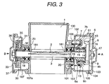
- FIG. 3 is a cross-sectional view in the axial direction of the air flow passage 1 of the electronic control throttle device in accordance with the present invention
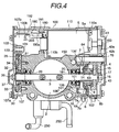
- FIG. 4 is a cross-sectional view in the direction perpendicular to the axis of the air flow passage 1 of the electronic control throttle device seeing from the upstream side.
- a gear case 102 for containing the gear mechanism 4 is formed on one side wall of the throttle body 100 integrally with the throttle body, and a bearing containing boss 101 for containing one of bearings 20 of the throttle valve shaft 3 is arranged in projecting on an outer wall of the throttle body 100 inside the gear case 102.
- the bearing 20 is sealed by a seal member 18 supported by a seal push 19.
- a spring (in this case, the returning spring) 7 out of the springs 7, 8 arranged outside (having a larger diameter) is fixed to the spring fastening portion 10 (refer to FIG. 1, FIG. 2, FIG. 3) of the throttle body 100 in one end 7a, and a part of the spring in the side of the one end 7a is guided on the outer periphery of the boss 101.
- annular groove 106 receiving a part of the returning spring 7 is formed between the outer periphery of the bearing containing boss 101 in the side of the gear case 102 and the inner wall of the gear case 102.
- the bottom portion of the annular groove 106 is not even in depth because of securing positions for attaching holes 150, as shown by the reference characters 106', 106'' in FIG. 4. Therefore, a plurality of ribs 151 are arranged in the circumferential direction of the annular groove 106 so as to receive the returning spring 7 at a constant level of depth of the annular groove 106. If the bottom portion of the annular groove 106 is even, the above-described ribs 151 can be eliminated and the returning spring 7 can be inserted a more deeper level of the annular groove 106.
- the default lever (the moving side engaging element) 6 is a disk shape having the arms 61, 62, and one surface of the default lever receives one end of the default spring 8 and the other surface in the opposite side receives one end of the default spring 8.
- the default lever (the moving side engaging element) 6 is composed of a cylinder portion with bottom 6a having an inner diameter slightly larger than an outer diameter of a spring 8 having a smaller diameter out of the default spring 8 and the returning spring 7 and an alligator portion 6b formed in the peripheral edge of an opening of the cylinder portion with bottom 6a, and a part of the spring 8 having a smaller diameter is inserted inside the cylinder portion with bottom 6a and received by the bottom of the cylinder portion with bottom 6a.
- a part of the spring 7 having a larger diameter is inserted on the outer periphery of the cylinder portion with bottom 6a and received by one surface of the alligator portion 6b.
- the default lever 6 is joined with a sleeve 63 inserted on the throttle valve shaft 3 in a unit, and holders (collars) of the default spring 8 is inserted on the outer periphery of the sleeve 63 between the throttle gear 43 and the default lever 6.
- the default lever (the moving side engaging element) 6 is placed between the wall portion of the throttle body 100 and the gear (the fixing side engaging element) 43, and the cylindrical collar divided into two members 14, 15 in the axial direction is placed between the inner periphery of the default spring 8 between the default lever 6 and the gear 43 and the outer periphery of the throttle valve shaft 3.
- the returning spring 7, the spring holder 13, the default lever 6, the collar member 14, the default spring 8, the collar member 15, the throttle gear 43, the spring fastening member 9 can be successively assembled through one end of the throttle valve shaft 3, and then the springs 7, 8 can be placed in compression states by fastening the nut 17 through a washer 16.
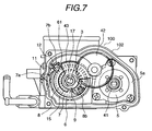
- FIG. 7 is a view showing the gear case 102 removing a gear cover 103 and seeing from a direction shown by an arrow A of FIG. 3.
- the default spring 8 and the returning spring 7 are nearly coaxially arranged partially overlapping and displacing in the axial direction around the throttle valve shaft 3.
- the diameter of the throttle gear 43 is made larger than the outer diameter of the returning spring 7 placed outside out of the default and returning springs so that the returning spring does not interfere with the other parts, and the throttle gear 43 and the smaller diameter gear 42b of the intermediate gear 4 are engaged with each other without difficulty.
- the default stopper 11 and the full close stopper 12 are attached on the side wall of the gear case in the throttle body 100.
- the returning spring 7 and the default spring 8 can be intensively arranged between the gear 43 provided in the throttle valve shaft 3 and the wall portion of the throttle body 100.
- the arranging space in the longitudinal direction of the spring can be shortened (that is, the spring receiving structure of the default lever 6 makes a part of the returning spring 7 and a part of the default spring 8 overlapped in the axial direction), and further, the returning spring 7 is guided on the outer periphery of the bearing containing boss 101 for the throttle valve projecting toward the inside of the gear case 102 to use the outer periphery of the bearing containing boss 101 for the arranging space of the returning spring 7.
- the gear 43 also serves as the stopper stopping element. Therefore, the parts are substantially made intensive and rational by the multiplier effect of the above to contribute to making the gear case 10 and the whole throttle body 100 small in size
- the motor case 110 integrated with the throttle body 100 has a motor inserting port 110a opening to the inside of the gear case 102.
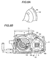
- FIGS. 8A and 8B each is a view showing the inside of the gear case 102 by removing the intermediate gear 42.
- the motor is designed as follows. That is, a contour of the motor bracket 5a is nearly triangular, and three sides forming the contour of the motor bracket are curved lines.
- the motor bracket 5a is attached to the motor case by fastening to triangular point arranged screw holes provided a periphery of the motor inserting port 110a with three screws 160 in total, and motor positioning portions 130, 131, 132 for positioning the motor by fitting to the three curved lines of the motor bracket 5a to position the motor being formed in the gear case 102.
- the inside of the motor positioning portions 130, 131, 132 has nearly equal curvature to the above-mentioned three sides of the curved lines of the motor bracket 5a.
- a part 70a of the outer periphery of a cylindrical portion 71 supporting the intermediate gear attaching shaft 70 also has a cut-off portion so as to trace a line extending the curved line of the above-mentioned motor positioning portion 130.
- the cut-off line 3a is also used as a part of curved line for positioning the motor, and accordingly the motor can be placed near the gear mechanism 4 side by the distance to improve the part configuration.
- a throttle sensor 30 for detecting throttle opening degree is attached to the other end of the throttle valve shaft 3 (an end in the side opposite to the gear mechanism 4 and the default opening degree setting mechanism).
- the throttle sensor 30 is composed of a sensor housing 31, a board 32 provided in the housing 31, a rotor 33, a brush 34 provided in the rotor 33 and a cover 35, and the sensor housing 31 having the board 32 is attached to the side wall of the throttle body 100 with screws in a state of inserting on to one end of the throttle valve shaft 3.
- the rotor having the brush 34 is fit to the throttle valve shaft 3 and fixed to the throttle valve shaft 3 fastened with a nut 36 so as to rotate together with the throttle valve shaft 3.
- a case 107 for containing the throttle sensor 30 is formed on the side wall of the throttle body 100 in the side opposite to the gear case 102.
- the case 107 also has a containing space (a containing portion) 107b for a connector 190 of lead wires (electric power supply wires) 205 to be connected to a terminal 51 (refer to FIG. 10, FIG. 11) in addition to a containing space 107a for the throttle sensor 30, and the sensor containing space 107a and the connector containing space 107b are constructed in one room without boundary. Therefore, here, the case 107 is called as a connector and throttle sensor case.
- the motor case 110 provided in the throttle body 100 and the connector and throttle sensor case 107 are arranged so as to intersect each other at right angle, and a motor terminal extracting port 180 is formed in the side of the bottom portion 110b of the motor case 110, and the containing space 107b for the connector 190 is formed adjacent to the side of the bottom portion 110b of the motor case.
- FIG. 10 is a view showing the throttle sensor case 107 of the throttle body 100 removing the case cover 37 and seeing from the direction shown by an arrow B of FIG. 3
- the wire lead portion 30a of the throttle sensor 30 is arranged so as to directed to the motor terminal connector containing space 107b.
- the throttle sensor 30 has two sensor detecting portions of same type in order to back up the sensor when one of the sensor detecting portions produces trouble, and accordingly there are two set of the wires 204 extracted from the sensor 30.
- the connector and throttle sensor case 107 is covered with a cover 37, and a wiring guide 123 for gathering and guiding the electric power supply wires 205 to be connected to a connector and the lead wires 204 of the throttle sensor 30 is fit into a groove 122 provided on the wall portion of the connector and throttle sensor case 107 to be attached with the cover 37.
- the wiring guide 123 is formed of a rubber plate, and has a plurality of guide holes 124 used for penetrations of the electric power supply wires 205 and the sensor lead wires 204.
- the wiring extracting portion 30a of the throttle sensor 30 is placed directing to the motor terminal connector containing space 107b as described above, the wires 204 led from the terminal of the throttle sensor 30 and the wires 205 led from the motor terminal 51 through the connector 190 can be merged at adjacent positions in the beginning in the one room, and accordingly these wires can be gathered without difficulty and can be extracted out of the throttle body. Therefore, this construction is useful to simplify the wiring work and the part assembling work.
- an electromagnetic shield member 206 of the wires 204, 205 is a woven shield composed of a tube-shaped member formed by weaving glass fiber and a woven thin metal wire member covering the tube-shaped member.
- the motor terminal extracting port 180 provided in the bottom portion of the motor case 110 is exposed to the connector containing portion (the containing space) 107b, and the guide 155 for guiding the connector to the motor terminal extracting port 180 when the connector is plugged to the motor terminal 51 is formed on the inner wall surface of the containing portion 107b of the motor terminal connector 190.
- FIG. 10 is a view showing the inside of the connector and throttle sensor case 107 detaching the motor terminal connector 190 and seeing from the side of the case opening.
- FIG. 13 is a C-C line cross-sectional view showing the motor terminal connector under a connecting process being taking on the plane of the line C-C of FIG. 10.
- the guide 155 is formed at mold forming of the throttle body 100 at the same time, and composed of a pair of opposite wall surfaces formed in such a shape that the width is wide in the receiving side of the connector and gradually narrowed toward the motor terminal extracting port 180.
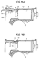
- FIG. 11 is a cross-sectional view showing the inner structure of the motor case 110 and the connector and throttle sensor case 107 seeing by changing the view angle from FIG. 13.
- FIG. 11A shows a state halfway through the process of plugging the connector
- FIG. 11B shows a state after plugging the connector 190 to the motor terminal 51.
- the connector 190 can be easily connected to the motor terminal 51 without difficulty of positioning the connector 190 to the motor terminal 51 because by containing the motor 5 in the motor case 110 the motor terminal 51 can be seen in the connector containing space 107b through the terminal extracting port 180, and in this state the motor terminal connector 190 is inserted from the terminal containing portion 107b using the guide 155. Even if the motor terminal 51 is, particularly, placed in a deep position of the connector containing portion 107b and behind the other parts, the connector can be inserted by being guided by the above-mentioned guide 155 without difficulty while being positioned.
- the motor terminal connector 190 is a plastic molded member of a socket type, and a pair of metal chips 191 for terminal connector is embedded in the motor terminal connector.
- the portion 190a embedding the metal chips 191 is formed in a nearly rectangular shape and a portion following to the portion 190a is formed in a plate with reinforcing rib 192 to rationalize use of material.
- the connector 190 is guided to the terminal extracting port 108 placed at a deep position through a narrow portion. Therefore, in order to make the plugging work easy, the length from the motor terminal extracting port 108 to a position near the opening of the connector and throttle sensor case 107 is shortened.
- a belt-shaped metal member 208 for holding the plurality of connectors 201 to 203 is welded on an outer surface of the cover 37 of the connector and throttle sensor case 107.
- wire connecting work can be easily performed without trouble of the layout configuration of the connector parts at assembling at the manufacturing location.
- the reference character 250 of FIG. 3 indicates an engine cooling water inlet pipe.
- the coil-shaped torsion spring is used for the returning spring 7 and the default spring 8 in this embodiment, but it is not limited to the coil-shaped torsion spring.
- a belt-shaped coil spring may be used.
- An embodiment of FIG. 15 employs a belt-shaped coil spring for the default spring 8, but the other structure is the same as that of the first embodiment. According to this type, the inside of the gear case can be made smaller.
- FIG. 14 eliminates the collar members 14, 15, but the other structure is the same as that of the first embodiment.
- the returning spring 7 is placed outside the default spring 8.
- the gear (the fixing side engaging element) 43 fixed to the throttle valve shaft 3 and the default lever 6 idly inserted onto the throttle valve shaft 3 and rotatable relative to the throttle valve shaft are connected with the returning spring 7 so as to attract each other.
- this connection can be performed by fastening one end of the returning spring 7 to the default lever 6 and the other end of the returning spring 7 to a spring fastening portion 9 of the throttle valve shaft 3.
- the default spring 8 acts a force on the default lever 6 in a direction to open the throttle valve by fastening one end 8a of the default spring 8 to a spring fastening portion 10 provided in the throttle body 100 and the other end 8b to a spring fastening portion 61 of the default lever 6.
- the gear (the fixing side engaging element) 43 and the default lever (the moving side engaging element) 6 are rotatable in being engaged together opposing against the force of the default spring 8 within the range of opening degrees below the default opening degree.
- the default lever 6 is blocked to move by the default opening degree setting stopper 11' and only the throttle gear 43 becomes rotatable opposing against the force of the returning spring 7 together with the throttle valve shaft 3 within the range of opening degrees above the default opening degree.
- the diameter of the default spring 8 is larger than the diameter of the returning spring 7, and the springs are arranged around the shaft of the throttle valve shaft 3 so that the default spring 8 is outside and the returning spring 7 is inside.
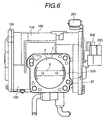
- the gap (the shaft supporting gap) between the throttle valve shaft 3 and the shaft inserting through hole 181 for guiding the throttle valve shaft 3 to the bearing 20 provided in the wall portion of a throttle body is filled with an air leak preventing material.
- the air leak preventing material for example, a dryable liquid lubricant such as molybdenum disulfide (MoS 2 ) is applied from downstream side of the throttle valve 2 onto the limited areas of gap between the throttle valve shaft 3 and the shaft inserting through holes 181 and the surrounding such as the diagonally shaded areas shown by the reference character 310 in FIG. 6, and penetrates and fills the shaft supporting gap.
- the minimum opening degree on the control purpose of the throttle valve can be increased larger than in the conventional one by that amount.
- the minimum opening degree on the control purpose is set a value lager than the overshoot of the throttle valve when opening degree of the throttle valve is changed from the maximum opening degree on control purpose of the throttle valve to the minimum opening degree.
- the minimum opening degree on the control purpose can be set a value lager than the mechanical full close position by approximately 2° (in a conventional case, a value lager than the mechanical full close position by approximately 1° )
- the minimum opening degree on the control purpose can be increased higher by a value corresponding to the overshoot (for instance, approximately 1.5° ) when opening degree of the throttle valve is changed from the maximum opening degree on control purpose (the electrical full open position) to the minimum opening degree (the electrical full close position) as shown by the line 2 ⁇ . Therefore, the stopper blocking element in the side of the throttle valve can be prevented from hitting on the stopper (the full close stopper) determining the mechanical full close position even if the overshoot occurs. Accordingly, even if the overshoot occurs, it is possible to prevent over current from flowing in the motor.
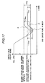
- FIG. 18 is a graph showing variations in air flow rate versus throttle valve opening degree in a case where an air leakage preventing member is applied along the whole circumference of the throttle valve in the air flow passage of the electronic control throttle and in a case where the air leakage preventing member is applied and filled only in the shaft support gap.
- an electronic control throttle device having an electric drive actuator, a gear mechanism, a default opening degree setting mechanism can be made small in size, light in weight and simple in assembling and wire harness.
- reliability of the electronic control throttle device can be improved by preventing the throttle valve from hitting on a stopper at the mechanical full close position even if an overshoot specific to the electronic control throttle device occurs when the throttle valve rapidly changes from the maximum opening degree on the control purpose to the minimum opening degree.
Abstract
Description
- The present invention relates to a throttle apparatus for an internal combustion engine and, more particularly, to an electronic control throttle device which controls opening and closing a throttle valve by driving an electric driven actuator based on a control signal.
- In the electronic control throttle apparatus for controlling a throttle valve of an engine by driving an electric driven actuator (for example, a direct current motor, a stepping motor), a technology known is that an initial opening degree (default opening degree) of the throttle valve in an off state of engine key (in other words, at not energized state of the electric driven actuator) is set to a position larger than its full close position.
- Here, the full close position does not mean a position for completely choking the intake air passage. Particularly, in a throttle device performing idling rotating speed control using only a throttle valve without any bypass passage for bypassing the throttle valve, the full close position is defined by classifying into a mechanical full close position and an electrical full close position to be described below.
- The mechanical full close position means a minimum opening degree position of a throttle valve determined by a stopper, and the minimum opening degree is set at a position to slightly open the throttle valve from a position to completely choking the intake air passage in order to prevent the throttle valve from sticking. The electrical full close position means a minimum opening degree within a range of opening degrees used for control, and the minimum opening degree is set at an opening position slightly larger than the mechanical full close position in taking the mechanical full close position as the reference by controlling of driving the electric driven actuator (for instance, a position larger than the mechanical full close position by approximately 1° ). In the electronic control throttle device, the electrical full close position (the minimum opening degree on the control purpose) does not always agree with an idling opening degree (an opening degree necessary for idling rotating speed control). The reason is that because the opening degree of the throttle valve is feedback controlled based on an idling rotating speed detected signal in order to keep the idling rotating speed to a target rotating speed, and thereby the opening degree can not be determined uniquely.
- In regard to a full open position, there are a mechanical full open position determined by a stopper and an electrical full open position of a maximum opening degree on control. Therein, in a case of simply describing a "full close position", meaning of the word includes the electrical full close position as well as the mechanical full close position. In a normal control, the throttle valve is controlled between the electrical full close position (the minimum opening degree on the control purpose) and the electrical full open position (the maximum opening degree on the control purpose). By doing so, a part of the throttle valve does not hit on the stoppers for determining the mechanical full close position and the mechanical full open position at controlling the throttle valve to the minimum and the maximum opening degrees. Therefore, mechanical fatigue, abrasion and damage of the stoppers and the gear members can be prevented and sticking of the throttle valve to the stopper can be prevented.
- A default opening degree (that is, the initial opening degree in an off state of engine key) is set to an opening degree of a position in which the throttle valve is further opened wider than that in the full close position (the mechanical full close position and the electrical full close position)(for example, a position larger than the mechanical full close position by 4 to 13° ). One reason why the default opening degree is set is that an air flow rate necessary for combustion of pre-warming-up operation at stating -up of the engine (cold starting-up) is secured without any auxiliary air passage (an air passage bypassing the throttle valve). During idling operation, as the engine is warmed up, the throttle valve is controlled so as to moved from the default opening degree toward the smaller opening degree. However, the lower limit is the electrical full close position. Another reason why the default opening degree is set is to cope with requirements for securing self-running (limp home) or for securing an intake air flow rate to prevent the engine operation from stopping even if the throttle control system is failed, for preventing the throttle valve from fixing to an inner surface of the throttle body with a viscous substance or ice.
- As conventional examples of default opening degree setting mechanisms, various kinds of default opening degree setting mechanisms are proposed in, for example, Japanese Patent Application Laid-Open No.63-150449, USP 4,947,815 and the corresponding patent of Japanese Patent Application Laid-Open No.2-500677, Japanese Patent Application Laid-Open No.62-82238 and the corresponding patent of USP 4,735,179 by the same applicant of the present invention, Japanese Patent Application Laid-Open No.10-89096, Japanese Patent Application Laid-Open No.10-131771 and so on.
- There are various types of default opening degree setting mechanisms. For example, one type is that a default opening degree is secured by setting the relationship between forces of a returning spring for acting a force toward a closing direction of the throttle valve and an opposed spring (called as a default spring or an initial opening degree spring) for acting a force toward an opening direction of the throttle valve opposing against the force of the returning spring so that the force of the default spring is larger than the force of the returning spring at the default opening degree position and so that a free end of the default spring is stopped by a default stopper at the default opening degree position when the engine key is switched off (for example, Japanese Patent Application Laid-Open No.2-500677).
- Another type is, as disclosed in Japanese Patent Application Laid-Open No.1-131771, that a fixing side engaging element to be fixed to a throttle valve shaft (this engaging element may be constructed by a throttle lever, or a gear for transmitting motor power may be used instead of the engaging element) and a moving side engaging element (a linking lever) idly inserted onto the throttle valve shaft and rotatable relative to the throttle valve shaft are provided, and the moving side engaging element and the fixing side engaging element are linked together with a returning spring so as to attract each other, and a force is applied using a default spring onto the moving side engaging element in a direction of opening the throttle valve to engage and rotate the moving side engaging element and the fixing side engaging element (the throttle valve shaft) together opposing against the force of the default spring when the opening degree is within the range smaller than the default opening degree (smaller than the default stopper position), and to rotate only the fixing side engaging element and accordingly the throttle valve shaft opposing against the force of the returning spring and preventing movement of the moving side engaging element by the default stopper when the opening degree is within the range larger than the default opening degree. On the contrary, there is a type that the moving side engaging element and the fixing side engaging element are linked together with the default spring so as to attract each other, and a force is applied using the returning spring onto the moving side engaging element in a direction of closing the throttle valve to engage and rotate the moving side engaging element and the fixing side engaging element (the throttle valve shaft) together opposing against the force of the returning spring when the opening degree is within the range larger than the default opening degree, and to rotate only the fixing side engaging element (the throttle valve shaft) opposing against the force of the default spring and preventing movement of the moving side engaging element by the default stopper when the opening degree is within the range smaller than the default opening degree.
- The electronic control throttle device can more accurately perform air flow rate control suitable for operation of an internal combustion engine than a mechanical throttle device in which an amount of stepping-in of the accelerator pedal is transmitted to a throttle valve shaft through an accelerator wire. However, since the electronic control throttle device has the electric drive actuator and the default opening degree setting mechanism, number of the parts is increased and accordingly it is important how to make the throttle body small in size, light in weight and simple in structure and how to simplify the wiring (wire harness).
- Further, the electronic control throttle device controls the idling rotating speed by controlling opening degree of the throttle valve, but has the following point to be improved.
- In a case where idling rotating speed control is performed with the throttle valve in the electronic control throttle device, an opening degree larger than the mechanical full close position by a certain angle (for example, 5 to 1° ) is secured at least as the minimum opening degree on the control purpose. Since a gap (sometime called as a shaft support gap) between the throttle valve shaft and a shaft inserting through hole provided in a wall of the throttle body which guides the throttle valve shaft to a bearing practically serves as a part of the intake air passage and the air flow rate (leak air flow rate) flowing through the shaft support gap can not be controlled, the minimum opening degree on the control purpose is set with taking it into consideration that the leak flow rate flows into the internal combustion engine.
- However, according to the conventional set value of the minimum opening degree for the control purpose (the electrical full close position), when the throttle valve is closed from the maximum opening degree for the control purpose (the electrical full open position) toward the minimum opening degree (the electrical full close position, in the idling state), a magnitude of overshoot becomes larger than the minimum opening degree in the closing direction (the overshoot is approximately 1.5° at maximum) because the driving force of the motor (the electric drive actuator) is decreased at high temperature or at low temperature (that is, the torque of the motor is reduced at high temperature due to increase in the resistance of the motor, and the torque of the motor is reduced at low temperature due to decease in the battery voltage). As a result, as shown by a
solid line 1 ○ in FIG. 17, the throttle valve hits on the stopper at the mechanical full close position (the diagonally shaded area in FIG. 17 indicates a state that movement of the throttle valve is blocked by the full close stopper.), and over-current flows in the motor likely to cause an erroneous fail-safe diagnosis (an erroneous diagnosis judging of occurrence of failure in the motor from the over current) or decrease in the lifetime of the motor. - An object of the present invention is to make an electronic control throttle device having an electric drive actuator, a gear mechanism, a default opening degree setting mechanism small in size, light in weight and simple in assembling and wire harness by solving the above-mentioned problems.
- Another object of the present invention is to improve reliability of the electronic control throttle device by preventing the throttle valve from hitting on the stopper even if such an overshoot as described above occurs in the throttle valve.
- The present invention is basically constructed as follows.
- A throttle device for an internal combustion engine according to one aspect of the present invention includes an electric drive actuator and a default opening degree setting mechanism, wherein
a gear case for containing a gear mechanism to transmit power of the electric drive actuator to a throttle valve shaft is arranged on an outer wall of a throttle body, and
a returning spring for acting a spring force on the throttle valve in a closing direction and a spring (a default spring) for acting a spring force on the throttle valve in a direction toward a side of the default opening degree seeing from the full close position of the throttle valve have diameters different from each other, and both of the springs are held around a shaft of said throttle valve shaft and arranged between a gear attached to the throttle valve shaft in the gear mechanism and a wall portion of the throttle body. - According to the above-mentioned construction, the returning spring and the default spring can be intensively arranged between the gear provided in the throttle shaft and the wall portion of the throttle body, and accordingly the part space can be rationalized. Particularly, according to the present invention, by arranging the returning spring and the default spring in such a feature that at least a part of the returning spring and a part of the default spring are overlapped with each other (one spring having a smaller diameter is inserted inside the other spring having a larger diameter), an arranging space in a longitudinal direction of the springs can be shortened, and accordingly this structure is useful in that the gear case and the whole throttle body can be made small in size, light in weight and simple in assembling.
- In addition to the above-mentioned construction, the present invention proposes a construction that the spring arranged outside out of the returning spring and the default spring (the spring having the larger diameter) is placed in being guided by an outer periphery of a bearing containing boss for the throttle valve shaft projecting inward of the gear case in a manner that one end of the spring having the larger diameter is fixed to the wall portion of the throttle body. By doing so, the outer periphery of the bearing containing boss for the throttle valve shaft can be used for a space placing one spring out of the returning spring and the default spring. Accordingly, this structure is useful in that the parts can be more intensively arranged, and the throttle body can be made smaller in size and light in weight. Although the other various dependent invention in regard to the first invention are proposed, these will be described in the item of DESCRIPTION OF THE PREFERRED EMBODIMENTS later.
- In an electronic control throttle device according to another aspect of the present invention, a throttle body, a motor case containing a motor composing an electric drive actuator and a containing portion of a connector connecting by plugging to a motor terminal provided in an end plate of said motor are formed in a unit. In addition, a motor terminal extracting port for exposing the motor terminal to the containing portion of the connector is formed on a bottom portion of the motor case, and a guide for guiding the connector to the motor terminal extracting port when the connector is plugged to the motor terminal is formed on an inner wall surface of the containing portion of the connector.
- By constructing as described above, the connector can be easily connected to the motor terminal without difficulty of positioning the connector to the motor terminal because by containing the motor in the motor case the motor terminal can be seen in the containing portion of the connector (the terminal connector) through the terminal extracting port, and in this state the terminal connector is inserted from the terminal containing portion using the guide. Even if the motor terminal is, particularly, placed in a deep position of the connector containing portion and behind the other parts, the connector can be inserted by being guided by the above-mentioned guide without difficulty while being positioned.
- In an electronic control throttle device according to a further aspect of the present invention, a motor case for containing a motor composing the electric drive actuator is integrated with a throttle body in a unit. In addition, in the throttle body, a motor terminal extracting port is formed in a side of a bottom portion of the motor case, a containing space of a connector to be connected to the motor terminal being formed adjacent to the side of the bottom portion of said motor case, the containing space of the connector and a containing space for containing a throttle sensor provided at one end of a throttle valve shaft being formed in one room, a wire lead portion of the throttle sensor being arranged in being directed to the containing space of the motor terminal connector.
- By constructing as described above, the wires led from the terminal of the throttle sensor and the wires led from the motor terminal can be merged at adjacent positions in the beginning in the connector and throttle sensor containing space (one room), and accordingly these wires can be gathered without difficulty and can be extracted out of the throttle body. Therefore, this construction is useful to simplify the wiring work and the part assembling work.
- An electronic control throttle device according to a further aspect of the present invention, a motor case for containing a motor composing the electric drive actuator and a gear case for containing a gear mechanism to transmit power of the motor to a throttle valve shaft are integrated in a unit. In addition, a motor inserting port of the motor case is opened to the gear case, the motor being attached to the motor case by fastening a motor bracket to triangular point arranged screw holes provided a periphery of the motor inserting port with three screws in total, three sides forming a contour of the motor bracket being curved lines, a motor positioning portion fitting to the three curved lines of the motor bracket to position the motor being formed in the gear case.
- By constructing as described above, vibration of the motor can be suppressed more effectively than in a conventional one in which the motor bracket is fastened at two points with screws, and further accuracy of positioning the motor can be improved.
- An electronic control throttle device according to a further aspect of the present invention includes an electric drive actuator for opening and closing a throttle valve based on a signal controlling an intake air flow rate of the internal combustion engine. In addition, a gap (a shaft supporting gap) between a throttle valve shaft and a shaft inserting through hole for guiding the throttle valve shaft to a bearing provided in a wall portion of a throttle body is filled with an air leak preventing material, and a minimum opening degree on control purpose of the throttle valve is set to a value larger than an amount of overshoot of the throttle valve occurring when opening degree of the throttle valve is changed from a maximum opening degree on control purpose of the throttle valve to the minimum opening degree.
- By constructing as described above, since the intake air flow rate (the leak air flow rate) supplied to the internal combustion engine through the so-called shaft supporting gap of the throttle valve shaft can be eliminated, the minimum opening degree on the control purpose of the throttle valve can be increased larger than in the conventional one by that amount. In the present invention, by making use of this fact the minimum opening degree on the control purpose is set a value lager than the overshoot of the throttle valve when opening degree of the throttle valve is changed from the maximum opening degree on control purpose of the throttle valve to the minimum opening degree. For instance, by applying the air leak preventing material (for example, molybdenum disulfide), as shown by the
solid line 2 ○ in FIG. 17, since the minimum opening degree on the control purpose can be set a value lager than the mechanical full close position by approximately 2° , the minimum opening degree on the control purpose can be increased higher by a value corresponding to the overshoot (for instance, approximately 1.5° ) when opening degree of the throttle valve is changed from the maximum opening degree on control purpose (the electrical full open position) to the minimum opening degree (the electrical full close position). Therefore, the stopper blocking element in the side of the throttle valve can be prevented from hitting on the stopper (the full close stopper) determining the mechanical full close position even if the overshoot occurs. Accordingly, even if the overshoot occurs, it is possible to prevent over current from flowing in the motor. - The above-mentioned operation and effect are attained on the premises that the gap (the shaft supporting gap) between the throttle valve shaft and the shaft inserting through hole for guiding the throttle valve shaft to the bearing provided in the wall portion of the throttle body is filled with the air leak preventing material. The above-mentioned operation and effect can not be expected in a mechanical throttle device in which a stepping amount of an accelerator is transmitted to a throttle valve shaft through an accelerator wire even if the so-called shaft supporting gap is filled with the air leak preventing material. The reason is as follows. The idling opening degree in the mechanical throttle device is set to a position where a mechanical full closing stopper exists, and the mechanical throttle device is designed on the premises that the stopper blocking element controlling the throttle valve hits on the full close stopper during operation. Further, since the throttle valve is mechanically driven using the accelerator wire, there is no occurrence of overshoot nor occurrence of over current attendant on the overshoot differently from in the electronic control throttle device.
- The Japanese Patent Application Laid-Open No.62-17100 proposes a technology that in a mechanical throttle device, a dryable liquid lubricant (for example, molybdenum disulfide) is penetrated into an air passage formed between a throttle valve shaft and a shaft inserting through hole in a wall portion of the throttle valve assembly (the shaft supporting gap) and dried to fill the air passage with the lubricant solidified and fixed to the air passage. On the background that an idling rotating speed of an engine is set in taking the amount of the air flowing through the so-called shaft supporting gap into consideration since the air flowing through the gap can not be controlled by the throttle valve, but the idling rotating speed is gradually decreased and finally the engine may be stopped because combustion products (combustion soot, viscous substance or the like) are gradually accumulated in the shaft supporting gap. Therefore, the setting of the idling rotating speed is performed by eliminating the gap in the beginning to eliminate the change in the idling air flow rate with time and by using a full close stopper (an idling adjust screw).
- In the electronic control throttle type, the idling rotating speed control can be performed by controlling the throttle valve opening degree through feedback control (that is, the idling opening degree is not determined using the idling adjusting screw used in the mechanical throttle device). Therefore, even if combustion products are gradually accumulated in the shaft supporting gap of the throttle valve shaft, decrease in the air flow rate (decrease in the idling rotating speed) caused by the accumulation of the combustion products can be compensated by controlling the throttle valve opening degree. From this point of view, the above-mentioned problem specific to the mechanical throttle device (the problem of the decrease in idling rotating speed caused by accumulation of combustion products in the shaft supporting gap) does not occur in the electronic control throttle device. In other words, there are differences in problem to be solved and in object between the air leak preventing material applied to the shaft supporting gap in the electronic control throttle device and the air leak preventing material applied to the shaft supporting gap in the mechanical throttle device.
- In an electronic control throttle device according to a further aspect of the invention, an electromagnetic shield member of a wire used for driving control of the electric drive actuator is a woven shield composed of a tube-shaped member formed by weaving glass fiber and a woven thin metal wire member covering the tube-shaped member.
- A conventional electromagnetic shield member of this kind is formed by covering a tube made of silicon rubber with a shielding outer cover of woven thin metal wires. The electromagnetic shield member of the above-mentioned structure can substantially reduce its cost and can effectively shield electromagnetic wave compared to the conventional electromagnetic shield member.
-
- FIGS. 1A and 1B each is a perspective view showing a first embodiment of an electronic control throttle device in accordance with the present invention and a view explaining the principle.
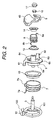
- FIG. 2 is an exploded perspective view showing a part of the first embodiment of the electronic control throttle device.
- FIG. 3 is a vertical cross-sectional view of the first embodiment.
- FIG. 4 is a transverse cross-sectional view of the first embodiment.
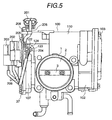
- FIG. 5 is a front view of the first embodiment.
- FIG. 6 is a rear view of the first embodiment.
- FIG. 7 is an explanatory view showing a gear case detaching its cover, the gear case being provided in the throttle body of the first embodiment.
- FIGS. 8A and 8B each is an explanatory view showing the gear case of FIG. 7 detaching part of the gears.
- FIG. 9 is a view showing a one side of the throttle body of FIG. 7.
- FIG. 10 is an explanatory view showing a connector and throttle sensor case detaching its cover, the connector and throttle sensor case being provided in the throttle body of the first embodiment.
- FIGS. 11A and 11B each is an explanatory view showing the process of connecting a motor terminal with a terminal connector used in the above-mentioned embodiment.
- FIG. 12 is a perspective view showing the terminal connector.
- FIG. 13 is a cross-sectional view showing the motor case and connecting terminal connector provided in the throttle body of the first embodiment.
- FIG. 14 is a vertical cross-sectional view showing a second embodiment in accordance with the present invention.
- FIG. 15 is a vertical cross-sectional view showing a third embodiment in accordance with the present invention.
- FIG. 16A and 16B each is a perspective view showing an outline of a fourth embodiment of an electronic control throttle device in accordance with the present invention and a view explaining the principle.
- FIG. 17 is a explanatory chart showing the relationship between overshoot occurring in the electronic control throttle and the minimum opening degree for the control purpose of the throttle valve.
- FIG. 18 is a graph showing variations in air flow rate versus throttle valve opening degree in a case where an air leakage preventing member is applied along the whole circumference of the throttle valve in the air flow passage of the electronic control throttle and in a case where the air leakage preventing member is applied and filled only in the shaft support gap.
-
- Embodiments of the present invention will be described below, referring to the accompanied drawings.
- Initially, the principle of an embodiment of an electronic control throttle device with a default mechanism (a throttle device of an internal combustion engine for a vehicle) in accordance with the present invention will be described below, referring to FIGS. 1A and 1B. FIG. 1A is a schematic perspective view showing an electric drive mechanism of throttle valve and a default mechanism in the present embodiment, and FIG. 1B is an explanatory view equivalently expressing the above-mentioned mechanisms.
- Referring to FIGS.1A and 1B, a flow rate of air flowing in an
intake air passage 1 is adjusted corresponding to an opening degree of a disk-shapedthrottle valve 2. Thethrottle valve 2 is fixed to athrottle valve shaft 3. In one end of thethrottle valve shaft 3, a final stage gear (referred to as a throttle gear) 43 of a gear mechanism (a reduction gear mechanism) 4 for transmitting power of a motor (an electric drive actuator) 5 to thethrottle valve shaft 3 is attached. Thegear mechanism 4 is composed of apinion gear 41 attached to themotor 5 and anintermediate gear 42 in addition to thethrottle gear 43. Theintermediate gear 42 is composed of alarge diameter gear 42a engaging with thepinion gear 41 and asmall diameter gear 42b engaging with thethrottle gear 43, and is rotatably inserted into agear shaft 70 fixed to a wall surface of athrottle body 100. - The
motor 5 is driven corresponding to an accelerator signal in regard to a stepping amount of an accelerator pedal and a traction control signal, and the power of the motor is transmitted to thethrottle valve shaft 3 through thegears - The throttle gear is a sectorial gear and fixed to the
throttle valve shaft 3, and also serves as a fixed side engaging element, to be described later, in order to reduce number of parts, and has anengaging side 43a for engaging with anarm portion 62 of an engaging lever (a moving side engaging element) 6 to be described later. - The engaging
lever 6 is used for a default opening degree setting mechanism, and therefore, is hereinafter referred to as a default lever. Thedefault lever 6 is idly inserted onto thethrottle valve shaft 3 and rotatable relative to the throttle valve shaft, and is an engaging element in the moving side to the above-mentioned fixing side engaging element (gear) 43. The fixing side engaging element (gear) 43 and the moving side engaging element (the default lever) 6 are attracted to each other through adefault spring 8 by connecting between a spring fastening portion (shown by areference character 64 in FIG. 2) of thedefault lever 6 and aspring fastening portion 9 fixed to thethrottle valve shaft 3 with thedefault spring 8. - A returning
spring 7 is fixed to aspring fastening portion 10 fixed to thethrottle body 100 in one end, and the other end of a free end side is hooked to aspring fastening portion 61 provided in thedefault lever 6 to act a force on the moving side engaging element (the default lever) 6 in a direction closing the throttle valve. - A full
close stopper 12 is for determining a mechanical full close position of the throttle valve. When thethrottle valve 2 is rotated toward a closing direction up to the mechanical full close position, one end of the stopper fixing element (herein, thethrottle gear 43 also serving) fixed to thethrottle valve shaft 3 is in contact with thestopper 12 to block the throttle valve to be closed further. A stopper (sometimes called as a default stopper) 11 for setting a default opening degree is for keeping the opening degree of thethrottle valve 2 to a preset initial opening degree (a default opening degree) larger than the mechanical full close position and the electrical full close position (a minimum opening degree on the control purpose) when an engine key is off (when the electric drive actuator is off). Thespring fastening portion 61 provided in thedefault lever 6 is in contact with thedefault stopper 11 when the throttle valve is in the default opening degree to block the throttle valve to rotate toward a direction decreasing the opening degree of the default lever 6 (a closing direction). The fullclose stopper 12 and thedefault stopper 11 are constructed by adjustable screws (adjust screws) provided in thethrottle body 100. - By constructing as described above, the fixing side engaging element (the throttle gear) 43 and the moving side engaging element (the default lever) 6 are set rotatable in being engaged together opposing against the force of the returning
spring 7 within the range of opening degrees above the default opening degree. The moving side engaging element (the default lever) 6 is set to be blocked to move by thedefault stopper 11 and only the fixing side engaging element (the throttle gear) 43 is set rotatable opposing against the force of thedefault spring 8 together with thethrottle valve shaft 3 within the range of opening degrees below the default opening degree. - For example, in FIGS. 1A and 1B, the engine key is in off state, and in this state the
default lever 6 is pushed back up to the position in contact with thedefault stopper 11 by the force of the returningspring 7, and thethrottle gear 43 and thethrottle valve shaft 3 are kept to be engaged with thedefault lever 6 and are at a position corresponding to the default opening degree by receiving the force of the returningspring 7 through the arm portion of thedefault lever 6. Therefore, a preset gap is maintained between the throttle gear (the stopper stopping element) 43 and the fullclose stopper 12. - When the
throttle valve shaft 3 is rotated from this state toward the opening direction by themotor 5 through thegear mechanism 4, thethrottle gear 43 transmits power in the opening direction to thedefault lever 6 through anengaging chip 43a and thearm portion 62 opposing against the force of the returningspring 7 to open thethrottle valve 2 up to a position where the power balances with the force of the returningspring 7. - On the contrary, when the
throttle valve shaft 3 is rotated from this state toward the closing direction by themotor 5 through thegear mechanism 4, the default lever 6 (the arm portion 61) follows the rotation of thethrottle gear 43 and thethrottle valve shaft 3 until thedefault lever 6 is in contact with thedefault stopper 11. When thedefault lever 6 is in contact with thedefault stopper 11, only thethrottle gear 43 and thethrottle valve shaft 3 are operated opposing against the force of thedefault spring 8 within the range below the default stopper 11 (the default opening degree) since thedefault lever 6 is blocked to rotate in the closing direction below the default opening degree. The throttle gear (the stopper stopping element) 43 is brought in contact with the fullclose stopper 12 at the mechanical full close position by driving themotor 5 only when the reference point on the control purpose is checked, and accordingly thethrottle gear 43 is normally not brought in contact with the fullclose stopper 12. - In this default method, the spring force of the returning
spring 6 is effective only within the range above the default opening degree due to existence of thedefault stopper 11. Therefore, since the spring force of thedefault spring 8 can be set within the range below the default opening degree without being affected by the spring force of the returningspring 6, there is an advantage in that load of the default spring is made small and accordingly the torque required for the electric drive actuator can be reduced and the electric load to the engine can be reduced. - In this embodiment, the returning
spring 7 and thedefault spring 8 are formed in coil-shaped torsion springs, and the diameter of the returningspring 7 is made larger than the diameter of thedefault spring 8, and thesesprings throttle valve shaft 3 and placed between thethrottle gear 43 and a wall portion of thethrottle body 100. By doing so, thedefault spring 8 and the returningspring 7 are partly overlapped in a nearly coaxial cylinder shape (that is, a part of thedefault spring 8 is inserted into the inside of the returningspring 7.) - In FIG. 1A, lengths of the
arm portions default lever 6 and the arm of the stoppingportion 9 are exaggeratively drawn for convenience of drawing the figure, but actually thesprings - FIG. 3 is a cross-sectional view in the axial direction of the
air flow passage 1 of the electronic control throttle device in accordance with the present invention, and FIG. 4 is a cross-sectional view in the direction perpendicular to the axis of theair flow passage 1 of the electronic control throttle device seeing from the upstream side. - As shown in these figures, a
gear case 102 for containing thegear mechanism 4 is formed on one side wall of thethrottle body 100 integrally with the throttle body, and abearing containing boss 101 for containing one ofbearings 20 of thethrottle valve shaft 3 is arranged in projecting on an outer wall of thethrottle body 100 inside thegear case 102. Thebearing 20 is sealed by aseal member 18 supported by aseal push 19. A spring (in this case, the returning spring) 7 out of thesprings throttle body 100 in oneend 7a, and a part of the spring in the side of the oneend 7a is guided on the outer periphery of theboss 101. - In this embodiment, an
annular groove 106 receiving a part of the returningspring 7 is formed between the outer periphery of thebearing containing boss 101 in the side of thegear case 102 and the inner wall of thegear case 102. The bottom portion of theannular groove 106 is not even in depth because of securing positions for attachingholes 150, as shown by the reference characters 106', 106'' in FIG. 4. Therefore, a plurality ofribs 151 are arranged in the circumferential direction of theannular groove 106 so as to receive the returningspring 7 at a constant level of depth of theannular groove 106. If the bottom portion of theannular groove 106 is even, the above-describedribs 151 can be eliminated and the returningspring 7 can be inserted a more deeper level of theannular groove 106. - The default lever (the moving side engaging element) 6 is a disk shape having the
arms default spring 8 and the other surface in the opposite side receives one end of thedefault spring 8. - The default lever (the moving side engaging element) 6 is composed of a cylinder portion with bottom 6a having an inner diameter slightly larger than an outer diameter of a
spring 8 having a smaller diameter out of thedefault spring 8 and the returningspring 7 and analligator portion 6b formed in the peripheral edge of an opening of the cylinder portion withbottom 6a, and a part of thespring 8 having a smaller diameter is inserted inside the cylinder portion with bottom 6a and received by the bottom of the cylinder portion with bottom 6a. On the other hand, a part of thespring 7 having a larger diameter is inserted on the outer periphery of the cylinder portion with bottom 6a and received by one surface of thealligator portion 6b. - The
default lever 6 is joined with asleeve 63 inserted on thethrottle valve shaft 3 in a unit, and holders (collars) of thedefault spring 8 is inserted on the outer periphery of thesleeve 63 between thethrottle gear 43 and thedefault lever 6. - That is, The default lever (the moving side engaging element) 6 is placed between the wall portion of the
throttle body 100 and the gear (the fixing side engaging element) 43, and the cylindrical collar divided into twomembers default spring 8 between thedefault lever 6 and thegear 43 and the outer periphery of thethrottle valve shaft 3. - In a case where the collar is divided into the
members throttle valve shaft 3 is rotated from the default opening degree toward the full open direction opposing against the force of thedefault spring 8, forces in directions opposite to each other are generated at the both ends of thedefault spring 8 caused by torsion. Therefore, when the collar member to serve as the spring holder is formed in one member, a large friction force caused by the torsion acts on the collar member from the returning spring. As a result, the collar member may be worn and damaged. On the other hand, when the collar member is divided into themembers collar members default spring 8, and the collar members do not receive an excessive force from the spring. Accordingly, the wear and damage described above can be prevented. - As shown in FIG. 2, the returning
spring 7, thespring holder 13, thedefault lever 6, thecollar member 14, thedefault spring 8, thecollar member 15, thethrottle gear 43, thespring fastening member 9 can be successively assembled through one end of thethrottle valve shaft 3, and then thesprings nut 17 through awasher 16. - FIG. 7 is a view showing the
gear case 102 removing agear cover 103 and seeing from a direction shown by an arrow A of FIG. 3. As described above, thedefault spring 8 and the returningspring 7 are nearly coaxially arranged partially overlapping and displacing in the axial direction around thethrottle valve shaft 3. The diameter of thethrottle gear 43 is made larger than the outer diameter of the returningspring 7 placed outside out of the default and returning springs so that the returning spring does not interfere with the other parts, and thethrottle gear 43 and thesmaller diameter gear 42b of theintermediate gear 4 are engaged with each other without difficulty. - The
default stopper 11 and the fullclose stopper 12 are attached on the side wall of the gear case in thethrottle body 100. - Main effects in regard to the construction having been described above are as follows.
- The returning
spring 7 and thedefault spring 8 can be intensively arranged between thegear 43 provided in thethrottle valve shaft 3 and the wall portion of thethrottle body 100. Particularly, by the structure that the returningspring 7 and thedefault spring 8 are arranged partially overlapping in the axial direction of the throttle valve shaft (the structure of arranging thesprings default lever 6 makes a part of the returningspring 7 and a part of thedefault spring 8 overlapped in the axial direction), and further, the returningspring 7 is guided on the outer periphery of thebearing containing boss 101 for the throttle valve projecting toward the inside of thegear case 102 to use the outer periphery of thebearing containing boss 101 for the arranging space of the returningspring 7. In addition, thegear 43 also serves as the stopper stopping element. Therefore, the parts are substantially made intensive and rational by the multiplier effect of the above to contribute to making thegear case 10 and thewhole throttle body 100 small in size, light in weight and simplifying assembling the throttle body. - The
motor case 110 integrated with thethrottle body 100 has amotor inserting port 110a opening to the inside of thegear case 102. - FIGS. 8A and 8B each is a view showing the inside of the
gear case 102 by removing theintermediate gear 42. In order to suppress vibration of the motor more effectively than a conventional one in which the motor bracket is fastened at two points with screws, and to improve accuracy of positioning, the motor is designed as follows. That is, a contour of themotor bracket 5a is nearly triangular, and three sides forming the contour of the motor bracket are curved lines. Themotor bracket 5a is attached to the motor case by fastening to triangular point arranged screw holes provided a periphery of themotor inserting port 110a with threescrews 160 in total, andmotor positioning portions motor bracket 5a to position the motor being formed in thegear case 102. The inside of themotor positioning portions motor bracket 5a. Further, apart 70a of the outer periphery of acylindrical portion 71 supporting the intermediategear attaching shaft 70 also has a cut-off portion so as to trace a line extending the curved line of the above-mentionedmotor positioning portion 130. The cut-off line 3a is also used as a part of curved line for positioning the motor, and accordingly the motor can be placed near thegear mechanism 4 side by the distance to improve the part configuration. - A
throttle sensor 30 for detecting throttle opening degree is attached to the other end of the throttle valve shaft 3 (an end in the side opposite to thegear mechanism 4 and the default opening degree setting mechanism). Thethrottle sensor 30 is composed of asensor housing 31, aboard 32 provided in thehousing 31, arotor 33, abrush 34 provided in therotor 33 and acover 35, and thesensor housing 31 having theboard 32 is attached to the side wall of thethrottle body 100 with screws in a state of inserting on to one end of thethrottle valve shaft 3. On the other hand, the rotor having thebrush 34 is fit to thethrottle valve shaft 3 and fixed to thethrottle valve shaft 3 fastened with anut 36 so as to rotate together with thethrottle valve shaft 3. By sliding a printed resistor on aboard 32 with thebrush 34 by rotation of therotor 33, an opening degree signal of the throttle valve is electrically output through a lead wire. - By providing the
throttle sensor 30, acase 107 for containing thethrottle sensor 30 is formed on the side wall of thethrottle body 100 in the side opposite to thegear case 102. Thecase 107 also has a containing space (a containing portion) 107b for aconnector 190 of lead wires (electric power supply wires) 205 to be connected to a terminal 51 (refer to FIG. 10, FIG. 11) in addition to a containingspace 107a for thethrottle sensor 30, and thesensor containing space 107a and theconnector containing space 107b are constructed in one room without boundary. Therefore, here, thecase 107 is called as a connector and throttle sensor case. - As shown in FIG. 4, the
motor case 110 provided in thethrottle body 100 and the connector andthrottle sensor case 107 are arranged so as to intersect each other at right angle, and a motorterminal extracting port 180 is formed in the side of thebottom portion 110b of themotor case 110, and the containingspace 107b for theconnector 190 is formed adjacent to the side of thebottom portion 110b of the motor case. By forming thesensor containing space 107a and theconnector containing space 107b as one room, as shown in FIG. 10 (FIG. 10 is a view showing thethrottle sensor case 107 of thethrottle body 100 removing thecase cover 37 and seeing from the direction shown by an arrow B of FIG. 3), thewire lead portion 30a of thethrottle sensor 30 is arranged so as to directed to the motor terminalconnector containing space 107b. - The
throttle sensor 30 has two sensor detecting portions of same type in order to back up the sensor when one of the sensor detecting portions produces trouble, and accordingly there are two set of thewires 204 extracted from thesensor 30. - As shown in FIGS. 5, 6, and 9, the connector and
throttle sensor case 107 is covered with acover 37, and awiring guide 123 for gathering and guiding the electricpower supply wires 205 to be connected to a connector and thelead wires 204 of thethrottle sensor 30 is fit into agroove 122 provided on the wall portion of the connector andthrottle sensor case 107 to be attached with thecover 37. Thewiring guide 123 is formed of a rubber plate, and has a plurality of guide holes 124 used for penetrations of the electricpower supply wires 205 and thesensor lead wires 204. - Since the
wiring extracting portion 30a of thethrottle sensor 30 is placed directing to the motor terminalconnector containing space 107b as described above, thewires 204 led from the terminal of thethrottle sensor 30 and thewires 205 led from themotor terminal 51 through theconnector 190 can be merged at adjacent positions in the beginning in the one room, and accordingly these wires can be gathered without difficulty and can be extracted out of the throttle body. Therefore, this construction is useful to simplify the wiring work and the part assembling work. - In order to reduce manufacturing cost, an
electromagnetic shield member 206 of thewires - The motor
terminal extracting port 180 provided in the bottom portion of themotor case 110 is exposed to the connector containing portion (the containing space) 107b, and theguide 155 for guiding the connector to the motorterminal extracting port 180 when the connector is plugged to themotor terminal 51 is formed on the inner wall surface of the containingportion 107b of themotor terminal connector 190. (refer to FIG. 10, FIG. 13. FIG. 10 is a view showing the inside of the connector andthrottle sensor case 107 detaching themotor terminal connector 190 and seeing from the side of the case opening. FIG. 13 is a C-C line cross-sectional view showing the motor terminal connector under a connecting process being taking on the plane of the line C-C of FIG. 10.) - The
guide 155 is formed at mold forming of thethrottle body 100 at the same time, and composed of a pair of opposite wall surfaces formed in such a shape that the width is wide in the receiving side of the connector and gradually narrowed toward the motorterminal extracting port 180. - FIG. 11 is a cross-sectional view showing the inner structure of the
motor case 110 and the connector andthrottle sensor case 107 seeing by changing the view angle from FIG. 13. FIG. 11A shows a state halfway through the process of plugging the connector, and FIG. 11B shows a state after plugging theconnector 190 to themotor terminal 51. - The
connector 190 can be easily connected to themotor terminal 51 without difficulty of positioning theconnector 190 to themotor terminal 51 because by containing themotor 5 in themotor case 110 themotor terminal 51 can be seen in theconnector containing space 107b through theterminal extracting port 180, and in this state themotor terminal connector 190 is inserted from theterminal containing portion 107b using theguide 155. Even if themotor terminal 51 is, particularly, placed in a deep position of theconnector containing portion 107b and behind the other parts, the connector can be inserted by being guided by the above-mentionedguide 155 without difficulty while being positioned. - As shown in FIGS. 4, 11A, 11B and 12, the
motor terminal connector 190 is a plastic molded member of a socket type, and a pair ofmetal chips 191 for terminal connector is embedded in the motor terminal connector. In this embodiment, theportion 190a embedding themetal chips 191 is formed in a nearly rectangular shape and a portion following to theportion 190a is formed in a plate with reinforcingrib 192 to rationalize use of material. Theconnector 190 is guided to the terminal extracting port 108 placed at a deep position through a narrow portion. Therefore, in order to make the plugging work easy, the length from the motor terminal extracting port 108 to a position near the opening of the connector andthrottle sensor case 107 is shortened. - As shown in FIGS. 5, 6 and 9, a belt-shaped
metal member 208 for holding the plurality ofconnectors 201 to 203 is welded on an outer surface of thecover 37 of the connector andthrottle sensor case 107. By attaching the plurality ofconnectors 201 to 203 to the belt-shapedmetal member 208 based on a predetermined layout, wire connecting work can be easily performed without trouble of the layout configuration of the connector parts at assembling at the manufacturing location. Thereference character 250 of FIG. 3 indicates an engine cooling water inlet pipe. - The coil-shaped torsion spring is used for the returning
spring 7 and thedefault spring 8 in this embodiment, but it is not limited to the coil-shaped torsion spring. For example, a belt-shaped coil spring may be used. An embodiment of FIG. 15 employs a belt-shaped coil spring for thedefault spring 8, but the other structure is the same as that of the first embodiment. According to this type, the inside of the gear case can be made smaller. - An embodiment of FIG. 14 eliminates the
collar members - In an embodiment of FIGS. 16A and 16B, contrary to the above-mentioned embodiments, the returning
spring 7 is placed outside thedefault spring 8. - The principle of the electronic control throttle device of FIGS. 16A and 16B is as follows.
- In this embodiment, the gear (the fixing side engaging element) 43 fixed to the
throttle valve shaft 3 and thedefault lever 6 idly inserted onto thethrottle valve shaft 3 and rotatable relative to the throttle valve shaft are connected with the returningspring 7 so as to attract each other. this connection can be performed by fastening one end of the returningspring 7 to thedefault lever 6 and the other end of the returningspring 7 to aspring fastening portion 9 of thethrottle valve shaft 3. - On the other hand, the
default spring 8 acts a force on thedefault lever 6 in a direction to open the throttle valve by fastening oneend 8a of thedefault spring 8 to aspring fastening portion 10 provided in thethrottle body 100 and theother end 8b to aspring fastening portion 61 of thedefault lever 6. - By constructing as described above, the gear (the fixing side engaging element) 43 and the default lever (the moving side engaging element) 6 are rotatable in being engaged together opposing against the force of the
default spring 8 within the range of opening degrees below the default opening degree. Thedefault lever 6 is blocked to move by the default opening degree setting stopper 11' and only thethrottle gear 43 becomes rotatable opposing against the force of the returningspring 7 together with thethrottle valve shaft 3 within the range of opening degrees above the default opening degree. In this embodiment, the diameter of thedefault spring 8 is larger than the diameter of the returningspring 7, and the springs are arranged around the shaft of thethrottle valve shaft 3 so that thedefault spring 8 is outside and the returningspring 7 is inside. - Although arrangement of the
springs - In each of the embodiment of the electronic control throttle device, the gap (the shaft supporting gap) between the
throttle valve shaft 3 and the shaft inserting throughhole 181 for guiding thethrottle valve shaft 3 to thebearing 20 provided in the wall portion of a throttle body is filled with an air leak preventing material. The air leak preventing material, for example, a dryable liquid lubricant such as molybdenum disulfide (MoS2) is applied from downstream side of thethrottle valve 2 onto the limited areas of gap between thethrottle valve shaft 3 and the shaft inserting throughholes 181 and the surrounding such as the diagonally shaded areas shown by thereference character 310 in FIG. 6, and penetrates and fills the shaft supporting gap. By filling the shaft supporting gaps with the air leak preventing material, since the intake air flow rate (the leak air flow rate) supplied to the internal combustion engine through the shaft supporting gap of the throttle valve shaft can be eliminated, the minimum opening degree on the control purpose of the throttle valve can be increased larger than in the conventional one by that amount. In the present invention, by making use of this fact the minimum opening degree on the control purpose is set a value lager than the overshoot of the throttle valve when opening degree of the throttle valve is changed from the maximum opening degree on control purpose of the throttle valve to the minimum opening degree. The operation and effects are as described in the section SUMMARY OF THE INVENTION. That is, by applying the air leak preventing material (for example, molybdenum disulfide), as shown in FIG. 17, since the minimum opening degree on the control purpose can be set a value lager than the mechanical full close position by approximately 2° (in a conventional case, a value lager than the mechanical full close position by approximately 1° ) , the minimum opening degree on the control purpose can be increased higher by a value corresponding to the overshoot (for instance, approximately 1.5° ) when opening degree of the throttle valve is changed from the maximum opening degree on control purpose (the electrical full open position) to the minimum opening degree (the electrical full close position) as shown by theline 2 ○ . Therefore, the stopper blocking element in the side of the throttle valve can be prevented from hitting on the stopper (the full close stopper) determining the mechanical full close position even if the overshoot occurs. Accordingly, even if the overshoot occurs, it is possible to prevent over current from flowing in the motor. - Further, by applying the air leak preventing material to the shaft supporting gaps and the surrounding, the following operation and effect can be obtained.
- That is, in a case of performing idling rotating speed control using the electronic control throttle device, in addition to the normal engine rotating speed feedback control there is a state of open control in order to cope with inrush load such as operation of an air conditioner. Further, in a gasoline engine directly injecting fuel into the engine (DI-G engine), since the required air flow rate is increased during stratified combustion (ultra-lean burn) regardless of the engine rotating speed (A/F = 40 : 1), there is a state of open control. Therefore, it is necessary to improve accuracy of air flow rate to throttle opening degree (particularly, accuracy near 1 to 7° ).
- However, when the air leak preventing material is applied onto the air passage wall along the whole circumference of the throttle valve, accuracy of air flow rate, particularly, accuracy in a low opening degree range has been low due to deviations in applying thickness and concentration of the air leak preventing material.
- On the other hand, when the air leak preventing material is not applied onto most part of the circumference of the throttle valve by limiting the applying area of the air leak preventing material only to the shaft support gap and the surrounding, the cause of the deviations can be eliminated and the accuracy of air flow rate can be improved. As an experimental result verifying the above-mentioned effect, FIG. 18 is a graph showing variations in air flow rate versus throttle valve opening degree in a case where an air leakage preventing member is applied along the whole circumference of the throttle valve in the air flow passage of the electronic control throttle and in a case where the air leakage preventing member is applied and filled only in the shaft support gap.
- According to the present invention, an electronic control throttle device having an electric drive actuator, a gear mechanism, a default opening degree setting mechanism can be made small in size, light in weight and simple in assembling and wire harness.
- Further, reliability of the electronic control throttle device can be improved by preventing the throttle valve from hitting on a stopper at the mechanical full close position even if an overshoot specific to the electronic control throttle device occurs when the throttle valve rapidly changes from the maximum opening degree on the control purpose to the minimum opening degree.
Claims (18)
- A throttle device for an internal combustion engine comprising an electric drive actuator (5), for opening and closing a throttle valve (2) to control an intake air flow rate of the internal combustion engine, and a default opening degree setting mechanism for keeping an opening degree of said throttle valve at a preset opening degree (hereinafter, the preset opening degree is defined as a default opening degree) larger than a full close position when said electric drive actuator (5) is not energized, wherein
a gear case (102) for containing a gear mechanism (4) to transmit power of said electric drive actuator (5) to a throttle valve shaft (3) is arranged on an outer wall of a throttle body (100), and
a returning spring (7) for acting a spring force on said throttle valve (2) in a closing direction and a spring (8) hereinafter, referred to as a default spring) for acting a spring force on said throttle valve (2) in a direction toward a side of the default opening degree seeing from the full close position of the throttle valve (2) have diameters different from each other, both of said springs (7, 8) being held around a shaft of said throttle valve shaft (3) and arranged between a gear attached to said throttle valve shaft (3) in said gear mechanism (4) and a wall portion of the throttle body (100). - A throttle device for an internal combustion engine according to claim 1, wherein at least a part of one spring among said returning spring (7) and said default spring (8) having a smaller diameter is inserted inside the other spring having a larger diameter, and the spring having the larger diameter is placed in being guided by an outer periphery of a bearing containing boss for the throttle valve shaft (3) projecting inward of said gear case (102) in a manner that one end of the spring having the larger diameter is fixed to the wall portion of the throttle body (100).
- A throttle device for an internal combustion engine according to any one of claim 1 and claim 2, wherein a diameter of a final stage gear (43) provided in said throttle valve shaft (3) is larger than an outer diameter of a spring having a larger outer diameter out of said returning spring (7) and said default spring (8), and said final stage gear (43) is engaged with an intermediate gear (42).
- A throttle device for an internal combustion engine according to any one of claim 1 to claim 3, which comprises an engaging element (hereinafter, referred to as a fixing side engaging element) fixed to said throttle valve shaft (3), and an engaging element (hereinafter, referred to as a moving side engaging element) idly inserted onto said throttle valve shaft (3) and rotatable relative to said throttle valve shaft (3), wherein said default spring (8) connects between a spring fastening portion of said moving side engaging element and a spring fastening portion of said throttle valve shaft so that said fixing side engaging element (43) and said moving side engaging element (6) attract each other, said returning spring (7) acting a force on said moving side engaging element (6) in the direction closing the throttle valve (2), said fixing side engaging element (43) and said moving side engaging element (6) being engaged and rotatable together opposing against a force of said returning spring (7) within a range of opening degrees larger than the default opening degree, only said fixed side engaging element (43) being set rotatable together with the throttle valve shaft (3) opposing against a force of said default spring (8) by blocking movement of said moving side engaging element (6) by a default opening degree setting stopper (11) within a range of opening degrees smaller than the default opening degree, said returning spring (7) and said default spring (8) being arranged around the shaft of said throttle valve shaft (3) so that said returning spring (7) is placed outside and said default spring (8) is placed inside.
- A throttle device for an internal combustion engine according to any one of claim 1 to claim 3, which comprises a fixing side engaging element (43) fixed to said throttle valve shaft (3) and a moving side engaging element (6) idly inserted onto said throttle valve shaft (3) and rotatable relative to said throttle valve shaft (3), wherein said returning spring (7) connects between a spring fastening portion of said moving side engaging element (6) and a spring fastening portion of said throttle valve shaft (3) so that said fixing side engaging element (43) and said moving side engaging element (6) attract each other, said default spring (8) acting a force on said moving side engaging element (6) in the direction opening the throttle valve (2), said fixing side engaging element (43) and said moving side engaging element (6) being engaged and rotatable together opposing against a force of said default spring (8) within a range of opening degrees larger than the default opening degree, only said fixed side engaging element (43) being set rotatable together with the throttle valve shaft (3) opposing against a force of said returning spring (7) by blocking movement of said moving side engaging element (6) by a default opening degree setting stopper within a range of opening degrees smaller than the default opening degree, said returning spring (7) and said default spring (8) being arranged around the shaft of said throttle valve shaft (3) so that said default spring (8) is placed outside and said returning spring (7) is placed inside.
- A throttle device for an internal combustion engine according to any one of claim 4 and claim 5, wherein said moving side engaging element (6) is placed between the wall portion of said throttle body (100) and said fixing side engaging element (43), and a cylindrical collar member divided into two portions in an axial direction is placed between an inner periphery of a spring out of said default spring (8) and said returning spring (7) placed between said moving side engaging element (6) and said fixing side engaging element (43) and an outer periphery of said throttle valve shaft (3).
- A throttle device for an internal combustion engine according to any one of claim 4 to claim 6, wherein the gear attached to said throttle valve shaft (3) in said gear mechanism (4) also serves as said fixing side engaging element (43).
- A throttle device for an internal combustion engine according to any one of claim 4 to claim 7, wherein said moving side engaging element (6) is composed of a cylinder portion with bottom (6a) having an inner diameter larger than an outer diameter of one spring out of said default spring (8) and said returning spring (7) having a smaller diameter and an alligator portion formed in an opening periphery of said cylinder portion with bottom, and a part of the other spring having a larger diameter is inserted on an outer periphery of said cylinder portion with bottom and supported with a surface of said alligator portion (6b).
- A throttle device for an internal combustion engine comprising an electric drive actuator (5) for opening and closing a throttle valve (2) to control an intake air flow rate of the internal combustion engine, wherein a throttle body (100), a motor case (110) containing a motor composing an electric drive actuator (5) and a containing portion of a connector (190) connecting by plugging to a motor terminal (51) provided in an end plate of said motor are formed in a unit, and
a motor terminal extracting port (180) for exposing said motor terminal (51) to said containing portion of the connector (190) is formed on a bottom portion (110b) of said motor case (110), and a guide for guiding said connector (190) to said motor terminal extracting port (180) when said connector (190) is plugged to said motor terminal (51) is formed on an inner wall surface of said containing portion of the connector (190). - A throttle device for an internal combustion engine comprising an electric drive actuator (5) for opening and closing a throttle valve (2) to control an intake air flow rate of the internal combustion engine, a motor case (110) for containing a motor composing said electric drive actuator (5) being integrated with a throttle body (100) in a unit, wherein
in said throttle body (100), a motor terminal extracting port (180) is formed in a side of a bottom portion (110b) of said motor case (110), a containing space (107b) of a connector (190) to be connected to the motor terminal (51) being formed adjacent to the side of the bottom portion (110b) of said motor case (110), the containing space (107b) of the connector (190) and a containing space (107a) for containing a throttle sensor (30) provided at one end of a throttle valve shaft (3) being formed in one room, a wire lead portion (30a) of said throttle sensor (30) being arranged in being directed to said containing space (107b) of the motor terminal connector (190). - A throttle device for an internal combustion engine according to claim 10, wherein a connector (190) and throttle sensor case (107) which forms said containing space (107b) of the motor terminal connector (190) and said containing space (107a) for containing the throttle sensor (30) in one room is covered with a cover (37), and a wiring guide (123) for gathering electric power wires (205) to be connected to said connector (190) and lead wires (204) of said throttle sensor (30) to one position to pass therethrough is inserted into a groove (122) provided on a wall portion of said connector (190) and throttle sensor case (107) to be attached with said cover (37).
- A throttle device for an internal combustion engine according to claim 11, wherein a belt-shaped metal member (208) for holding a plurality of connectors (201-203) is welded on an outer surface of said cover (37).
- A throttle device for an internal combustion engine comprising an electric drive actuator (5) for opening and closing a throttle valve (2) to control an intake air flow rate of the internal combustion engine, a motor case (110) for containing a motor composing said electric drive actuator (5) and a gear case (102) for containing a gear mechanism (4) to transmit power of said motor to a throttle valve shaft (3) being integrated in a unit, wherein
a motor inserting port of said motor case (110) is opened to said gear case (102), said motor being attached to said motor case (110) by fastening a motor bracket (5a) to triangular point arranged screw holes provided a periphery of said motor inserting port with three screws (160) in total, three sides forming a contour of said motor bracket (5a) being curved lines, a motor positioning portion fitting to the three curved lines of said motor bracket (5a) to position the motor being formed in said gear case (110). - A throttle device for an internal combustion engine comprising an electric drive actuator (5) for opening and closing a throttle valve (2) based on a signal controlling an intake air flow rate of the internal combustion engine, wherein
a gap between a throttle valve shaft (3) and a shaft inserting through hole for guiding said throttle valve shaft (3) to a bearing provided in a wall portion of a throttle body (100) is filled with an air leak preventing material, and a minimum opening degree on control purpose of said throttle valve (2) is set to a value larger than an amount of overshoot of said throttle valve (2) occurring when opening degree of said throttle valve (2) is changed from a maximum opening degree on control purpose of said throttle valve (2) to the minimum opening degree. - A throttle device for an internal combustion engine comprising an electric drive actuator (5) for opening and closing a throttle valve (2) based on a signal controlling an intake air flow rate of the internal combustion engine, wherein a gap between a throttle valve shaft (3) driven to open and close the throttle valve (2) by said electric drive actuator (5) and a shaft inserting through hole for guiding said throttle valve shaft (3) to a bearing (20) provided in a wall portion of a throttle body (100) is filled with an air leak preventing material.
- A throttle device for an internal combustion engine comprising an electric drive actuator (5) for opening and closing a throttle valve (2) based on a signal controlling an intake air flow rate of the internal combustion engine, wherein
a minimum opening degree on control purpose of said throttle valve (2) is set to such a value that said throttle valve (2) does not hit to a full close stopper (12) by an overshoot of said throttle valve (2) occurring when said throttle valve (2) is changed from a maximum opening degree on control purpose of said throttle valve (2) to the minimum opening degree. - A throttle device for an internal combustion engine according to any one of claim 14 and claim 15, wherein said air leak preventing material is molybdenum disulfide, and applied onto portions limited to between said throttle valve shaft (3) and said shaft inserting through hole and the surrounding among portions around an outer periphery of said throttle valve (2).
- A throttle device for an internal combustion engine comprising an electric drive actuator (5) for opening and closing a throttle valve (2) to control an intake air flow rate of an internal combustion engine, wherein an electromagnetic shield member (206) of a wire used for driving control of the electric drive actuator (5) is a woven shield composed of a tube-shaped member formed by weaving glass fiber and a woven thin metal wire member covering the tube-shaped member.
Priority Applications (4)
| Application Number | Priority Date | Filing Date | Title |
|---|---|---|---|
| EP04011537.0A EP1479892B2 (en) | 1998-10-06 | 1999-10-05 | Throttle apparatus for an internal combustion engine |
| EP04011542A EP1477650A3 (en) | 1998-10-06 | 1999-10-05 | Throttle apparatus for an internal combustion engine |
| EP05019356A EP1635052B2 (en) | 1998-10-06 | 1999-10-05 | Throttle apparatus for an internal combustion engine |
| EP05019357A EP1635053B1 (en) | 1998-10-06 | 1999-10-05 | Throttle apparatus for an internal combustion engine |
Applications Claiming Priority (2)
| Application Number | Priority Date | Filing Date | Title |
|---|---|---|---|
| JP28459198A JP3511577B2 (en) | 1998-10-06 | 1998-10-06 | Throttle device for internal combustion engine |
| JP28459198 | 1998-10-06 |
Related Parent Applications (1)
| Application Number | Title | Priority Date | Filing Date |
|---|---|---|---|
| EP05019357A Division EP1635053B1 (en) | 1998-10-06 | 1999-10-05 | Throttle apparatus for an internal combustion engine |
Related Child Applications (8)
| Application Number | Title | Priority Date | Filing Date |
|---|---|---|---|
| EP04011542A Division EP1477650A3 (en) | 1998-10-06 | 1999-10-05 | Throttle apparatus for an internal combustion engine |
| EP05019357A Division EP1635053B1 (en) | 1998-10-06 | 1999-10-05 | Throttle apparatus for an internal combustion engine |
| EP05019356A Division EP1635052B2 (en) | 1998-10-06 | 1999-10-05 | Throttle apparatus for an internal combustion engine |
| EP04011537.0A Division EP1479892B2 (en) | 1998-10-06 | 1999-10-05 | Throttle apparatus for an internal combustion engine |
| EP04011537.0 Division-Into | 2004-05-14 | ||
| EP04011542.0 Division-Into | 2004-05-14 | ||
| EP05019357.2 Division-Into | 2005-09-06 | ||
| EP05019356.4 Division-Into | 2005-09-06 |
Publications (3)
| Publication Number | Publication Date |
|---|---|
| EP0992662A2 true EP0992662A2 (en) | 2000-04-12 |
| EP0992662A3 EP0992662A3 (en) | 2002-09-18 |
| EP0992662B1 EP0992662B1 (en) | 2005-12-28 |
Family
ID=17680446
Family Applications (5)
| Application Number | Title | Priority Date | Filing Date |
|---|---|---|---|
| EP99119135A Expired - Lifetime EP0992662B1 (en) | 1998-10-06 | 1999-10-05 | Throttle apparatus for an internal combustion engine |
| EP05019357A Expired - Lifetime EP1635053B1 (en) | 1998-10-06 | 1999-10-05 | Throttle apparatus for an internal combustion engine |
| EP05019356A Expired - Lifetime EP1635052B2 (en) | 1998-10-06 | 1999-10-05 | Throttle apparatus for an internal combustion engine |
| EP04011542A Withdrawn EP1477650A3 (en) | 1998-10-06 | 1999-10-05 | Throttle apparatus for an internal combustion engine |
| EP04011537.0A Expired - Lifetime EP1479892B2 (en) | 1998-10-06 | 1999-10-05 | Throttle apparatus for an internal combustion engine |
Family Applications After (4)
| Application Number | Title | Priority Date | Filing Date |
|---|---|---|---|
| EP05019357A Expired - Lifetime EP1635053B1 (en) | 1998-10-06 | 1999-10-05 | Throttle apparatus for an internal combustion engine |
| EP05019356A Expired - Lifetime EP1635052B2 (en) | 1998-10-06 | 1999-10-05 | Throttle apparatus for an internal combustion engine |
| EP04011542A Withdrawn EP1477650A3 (en) | 1998-10-06 | 1999-10-05 | Throttle apparatus for an internal combustion engine |
| EP04011537.0A Expired - Lifetime EP1479892B2 (en) | 1998-10-06 | 1999-10-05 | Throttle apparatus for an internal combustion engine |
Country Status (4)
| Country | Link |
|---|---|
| US (9) | US6382180B2 (en) |
| EP (5) | EP0992662B1 (en) |
| JP (1) | JP3511577B2 (en) |
| DE (4) | DE69938011T3 (en) |
Cited By (8)
| Publication number | Priority date | Publication date | Assignee | Title |
|---|---|---|---|---|
| US6779775B2 (en) | 2002-07-31 | 2004-08-24 | Ab Elektronik Gmbh | Air flap system with a magnetic positioning spring |
| US6912994B2 (en) | 2002-10-25 | 2005-07-05 | Denso Corporation | Electronically controlled throttle control apparatus |
| EP1555408A1 (en) * | 2002-10-11 | 2005-07-20 | Mikuni Corporation | Multiple throttle device |
| WO2006048432A1 (en) * | 2004-11-05 | 2006-05-11 | Robert Bosch Gmbh | Method and device for triggering an actuator |
| DE102005051304A1 (en) * | 2005-10-26 | 2007-05-03 | Siemens Ag | Impurities cleaning method for gas feedback valve, involves providing valve flap that is connected with tooth segment, where toothed circles of segments comprise changeable radii with which shaft is provided with increasing torques |
| EP2239443A1 (en) * | 2009-03-31 | 2010-10-13 | Honda Motor Co., Ltd. | Throttle control system |
| IT201800006825A1 (en) * | 2018-06-29 | 2019-12-29 | ACTUATOR EQUIPPED WITH AN ELECTROMAGNETIC FIELD SHIELDING DEVICE FOR MAGNETIC OR MAGNETO-RESISTIVE POSITION SENSORS. | |
| US11193430B2 (en) | 2018-09-05 | 2021-12-07 | Honda Motor Co., Ltd. | General engine throttle apparatus |
Families Citing this family (53)
| Publication number | Priority date | Publication date | Assignee | Title |
|---|---|---|---|---|
| US6936538B2 (en) | 2001-07-16 | 2005-08-30 | Applied Materials, Inc. | Method and apparatus for depositing tungsten after surface treatment to improve film characteristics |
| JP3945568B2 (en) * | 2000-12-27 | 2007-07-18 | 株式会社デンソー | Intake control device for internal combustion engine |
| DE10102775A1 (en) * | 2001-01-23 | 2002-07-25 | Bosch Gmbh Robert | Manual return device for the choke flap of a combustion engine, has spring and cam mechanism with reduced play , so that the choke flap can be accurately positioned, should its electric drive fail |
| JP2003083095A (en) * | 2001-07-05 | 2003-03-19 | Denso Corp | Throttle device for engine |
| KR20030050446A (en) * | 2001-12-18 | 2003-06-25 | 현대자동차주식회사 | Electronic throttle valve control system for vehicles |
| JP2003185470A (en) * | 2001-12-18 | 2003-07-03 | Hitachi Ltd | Rotation position sensor, motor-operated throttle device, accelerator position sensor |
| JP2003262265A (en) * | 2002-03-08 | 2003-09-19 | Jatco Ltd | Method and structure for installing terminal connector |
| JP4394337B2 (en) * | 2002-08-29 | 2010-01-06 | 株式会社デンソー | Throttle valve device for internal combustion engine |
| US6874470B2 (en) | 2003-03-04 | 2005-04-05 | Visteon Global Technologies, Inc. | Powered default position for motorized throttle |
| DE602004030432D1 (en) * | 2003-03-20 | 2011-01-20 | Keihin Corp | FIXING PROCEDURE FOR THROTTLE BODY AND THROTTLE BODY |
| US7096851B2 (en) * | 2003-06-26 | 2006-08-29 | Honda Motor Co., Ltd. | Throttle device for multipurpose engine |
| DE102004016912A1 (en) * | 2003-08-07 | 2005-11-03 | Robert Bosch Gmbh | Actuator for the control of internal combustion engines |
| JP3936928B2 (en) * | 2003-09-26 | 2007-06-27 | 株式会社日立製作所 | Electric throttle device |
| JP2005133624A (en) * | 2003-10-30 | 2005-05-26 | Hitachi Ltd | Electronic control throttle device |
| US7114487B2 (en) * | 2004-01-16 | 2006-10-03 | Ford Motor Company | Ice-breaking, autozero and frozen throttle plate detection at power-up for electronic motorized throttle |
| JP4457038B2 (en) * | 2005-04-14 | 2010-04-28 | 日立オートモティブシステムズ株式会社 | Motor driven throttle control device for internal combustion engine |
| JP4801807B2 (en) * | 2005-07-14 | 2011-10-26 | 株式会社ケーヒン | Motor actuator |
| JP2007032618A (en) * | 2005-07-22 | 2007-02-08 | Taiho Kogyo Co Ltd | Valve assembly, valve position learning method, and valve position learning program |
| JP2007177747A (en) * | 2005-12-28 | 2007-07-12 | Denso Corp | Screwing device |
| JP4979364B2 (en) * | 2006-12-15 | 2012-07-18 | 株式会社ケーヒン | Throttle valve shaft support structure |
| JP2008190368A (en) * | 2007-02-02 | 2008-08-21 | Hitachi Ltd | Motor drive type throttle device for internal combustion engine |
| JP2008240610A (en) | 2007-03-27 | 2008-10-09 | Aisan Ind Co Ltd | Throttle device of internal combustion engine |
| JP4760763B2 (en) * | 2007-04-23 | 2011-08-31 | スズキ株式会社 | Electronically controlled throttle valve device |
| DE102007025441B4 (en) * | 2007-05-31 | 2020-06-18 | Continental Automotive Gmbh | Load adjustment device |
| US8357131B2 (en) * | 2008-09-18 | 2013-01-22 | Kci Licensing, Inc. | Laminar dressings, systems, and methods for applying reduced pressure at a tissue site |
| JP4801710B2 (en) * | 2008-09-22 | 2011-10-26 | 愛三工業株式会社 | Throttle control device for internal combustion engine |
| US20100301241A1 (en) * | 2009-05-27 | 2010-12-02 | Honeywell International Inc. | Valve assembly with dummy electrical connector port |
| JP5066142B2 (en) | 2009-06-18 | 2012-11-07 | 日立オートモティブシステムズ株式会社 | Motor-driven throttle valve device with inductive throttle sensor and inductive throttle sensor for detecting the rotation angle of the throttle shaft of the motor-driven throttle valve device |
| JP5184466B2 (en) * | 2009-08-28 | 2013-04-17 | 本田技研工業株式会社 | Electronic throttle control device |
| JP5197548B2 (en) * | 2009-11-05 | 2013-05-15 | 本田技研工業株式会社 | Fuel injection control device for internal combustion engine |
| JP5380337B2 (en) * | 2010-03-16 | 2014-01-08 | 本田技研工業株式会社 | Wiring structure to throttle body in small vehicle |
| JP5357105B2 (en) * | 2010-05-19 | 2013-12-04 | 株式会社デンソー | Throttle device |
| JP5673602B2 (en) * | 2012-05-28 | 2015-02-18 | 株式会社デンソー | Valve device |
| JP5672509B2 (en) * | 2012-11-28 | 2015-02-18 | 株式会社デンソー | Accelerator device |
| DE102013201170A1 (en) * | 2013-01-24 | 2014-07-24 | Mahle International Gmbh | Reset unit, in particular for an internal combustion engine |
| JP6203044B2 (en) * | 2013-12-26 | 2017-09-27 | 株式会社マーレ フィルターシステムズ | Intake control valve assembly structure and assembly method |
| JP6272200B2 (en) * | 2014-09-29 | 2018-01-31 | 日立オートモティブシステムズ株式会社 | Throttle device |
| JP6613032B2 (en) * | 2015-02-04 | 2019-11-27 | 株式会社ケーヒン | Electronically controlled throttle device |
| JP6725969B2 (en) * | 2015-07-10 | 2020-07-22 | 株式会社ケーヒン | Electronically controlled throttle device |
| CN108138660B (en) | 2015-09-25 | 2020-12-18 | 日产自动车株式会社 | Valve control device |
| JP2017067067A (en) | 2015-09-30 | 2017-04-06 | 株式会社デンソー | Torsion spring |
| CN105649784B (en) * | 2016-03-28 | 2018-10-26 | 江阴职业技术学院 | Engine exhaust throttling set and method for heavy motor truck auxiliary braking |
| JP6673022B2 (en) * | 2016-05-31 | 2020-03-25 | 富士通株式会社 | Electronic devices and beacons |
| CN106089450A (en) * | 2016-08-23 | 2016-11-09 | 无锡隆盛科技股份有限公司 | A kind of resetting-mechanism of electronic throttle |
| US10041420B2 (en) * | 2016-08-31 | 2018-08-07 | Borgwarner Inc. | Valve assembly and valve system including same |
| JP6394676B2 (en) * | 2016-10-21 | 2018-09-26 | トヨタ自動車株式会社 | Hybrid car |
| DE102017209458A1 (en) * | 2017-06-05 | 2018-12-06 | Siemens Schweiz Ag | Actuator with a return spring acting independently of the actuating operation on a control connection |
| CN109113874B (en) * | 2017-06-23 | 2024-01-12 | 纬湃汽车电子(芜湖)有限公司 | Throttle valve |
| CN108087127A (en) * | 2017-12-28 | 2018-05-29 | 无锡隆盛科技股份有限公司 | A kind of torque motor air throttle |
| JP6963519B2 (en) * | 2018-02-02 | 2021-11-10 | 株式会社ミクニ | Throttle device |
| DE102019103556A1 (en) * | 2019-02-13 | 2020-08-13 | Eberspächer Exhaust Technology GmbH & Co. KG | Exhaust flap |
| JP7259637B2 (en) * | 2019-08-19 | 2023-04-18 | 株式会社デンソーダイシン | Throttle valve device |
| CN114738124B (en) * | 2022-04-13 | 2023-03-28 | 温州市温纳汽车配件有限公司 | Electronic throttle valve and control method thereof |
Citations (11)
| Publication number | Priority date | Publication date | Assignee | Title |
|---|---|---|---|---|
| US4651041A (en) * | 1985-04-04 | 1987-03-17 | Aisin Seiki Kabushiki Kaisha | Electric motor |
| JPH02161137A (en) * | 1988-12-12 | 1990-06-21 | Mazda Motor Corp | Throttle valve opening detecting device for engine |
| DE3925702A1 (en) * | 1989-08-03 | 1991-02-07 | Bosch Gmbh Robert | Detachable electrical connection for electric motor - is assigned to motor mounting with plug contacts leading outwards from housing |
| JPH03271528A (en) * | 1990-03-22 | 1991-12-03 | Aisan Ind Co Ltd | Throttle valve control device |
| FR2676250A1 (en) * | 1991-05-06 | 1992-11-13 | Solex | Feed device for engine, with a spring for returning the restrictor member (choke) |
| JPH0797950A (en) * | 1993-09-29 | 1995-04-11 | Nippondenso Co Ltd | Throttle controller of internal combustion engine |
| WO1995014911A1 (en) * | 1993-11-20 | 1995-06-01 | Ab Elektronik Gmbh | Adjusting device |
| JPH08326561A (en) * | 1995-05-31 | 1996-12-10 | Nippondenso Co Ltd | Throttle control device for internal combustion engine |
| US5735243A (en) * | 1996-06-17 | 1998-04-07 | Aisan Kogyo Kabushiki Kaisha | Controller for preventing throttle valve from locking at its fully closed position |
| DE19756053A1 (en) * | 1996-12-17 | 1998-06-18 | Aisan Ind | Internal combustion (IC) engine throttle flap control device |
| DE19820421A1 (en) * | 1997-05-07 | 1998-11-12 | Hitachi Ltd | Throttle control for IC engine |
Family Cites Families (23)
| Publication number | Priority date | Publication date | Assignee | Title |
|---|---|---|---|---|
| JPS618430A (en) † | 1985-05-10 | 1986-01-16 | Hitachi Ltd | Throttle valve assembly |
| JPH0759901B2 (en) | 1985-10-04 | 1995-06-28 | 株式会社日立製作所 | Automatic throttle control device |
| DE3631283C2 (en) | 1986-09-13 | 1999-11-25 | Bosch Gmbh Robert | Device for the controlled metering of combustion air in an internal combustion engine |
| JP2550962B2 (en) | 1986-12-12 | 1996-11-06 | 日本電装株式会社 | Engine throttle valve control device |
| DE3890168T1 (en) † | 1987-03-02 | 1989-03-23 | Mitsubishi Electric Corp | RETURN DEVICE FOR AN INLET THROTTLE VALVE OF AN ENGINE |
| JP2690977B2 (en) * | 1988-03-18 | 1997-12-17 | 株式会社日立製作所 | Electronically controlled throttle valve for internal combustion engine |
| JP2513776B2 (en) * | 1988-04-01 | 1996-07-03 | 株式会社日立製作所 | Throttle valve control method and device |
| JP2559480B2 (en) * | 1988-11-07 | 1996-12-04 | 株式会社日立製作所 | Electronic valve opening controller |
| JPH04500711A (en) * | 1989-07-07 | 1992-02-06 | ローベルト・ボッシュ・ゲゼルシャフト・ミット・ベシュレンクテル・ハフツング | Internal combustion engine control device |
| JP2500677B2 (en) | 1991-12-17 | 1996-05-29 | 三菱瓦斯化学株式会社 | Improved non-aqueous solvent lithium secondary battery |
| DE4240783A1 (en) † | 1992-12-04 | 1994-06-09 | Vdo Schindling | Rotary potentiometer providing angular position signal - supports wiper shoe by two symmetrical arms of stamped sheet metal spring element |
| DE4337184A1 (en) † | 1993-10-30 | 1995-05-04 | Pierburg Gmbh | Throttle body |
| US5429090A (en) * | 1994-02-28 | 1995-07-04 | Coltec Industries Inc. | Fail safe throttle positioning system |
| JPH07324636A (en) * | 1994-04-04 | 1995-12-12 | Nippondenso Co Ltd | Throttle valve controller |
| DE9409891U1 (en) † | 1994-06-18 | 1994-08-11 | A B Elektronik Gmbh | Arrangement for the emergency driving position of a throttle valve element |
| DE19510622A1 (en) † | 1995-03-23 | 1996-09-26 | Bosch Gmbh Robert | IC engine throttle with throttle flap housing |
| US5522361A (en) * | 1995-09-07 | 1996-06-04 | Ford Motor Company | Throttle shaft seal for a throttle body |
| JP3192355B2 (en) † | 1995-09-20 | 2001-07-23 | 株式会社日立製作所 | Intake control device for internal combustion engine |
| US5640942A (en) * | 1996-01-16 | 1997-06-24 | Ford Motor Company | Ultraviolet cured throttle bore pre-coating |
| EP1326016A3 (en) | 1996-09-03 | 2012-08-29 | Hitachi Automotive Systems, Ltd. | A throttle valve control device for an internal combustion engine |
| JP3161978B2 (en) | 1996-09-12 | 2001-04-25 | 株式会社日立製作所 | Engine throttle device |
| DE19703296A1 (en) † | 1997-01-30 | 1998-08-06 | Mannesmann Vdo Ag | Method of sealing a throttle valve shaft carrying a throttle valve and throttle valve body |
| JP3361030B2 (en) | 1997-03-19 | 2003-01-07 | 株式会社日立ユニシアオートモティブ | Electronically controlled throttle valve device for internal combustion engine |
-
1998
- 1998-10-06 JP JP28459198A patent/JP3511577B2/en not_active Expired - Lifetime
-
1999
- 1999-10-05 EP EP99119135A patent/EP0992662B1/en not_active Expired - Lifetime
- 1999-10-05 EP EP05019357A patent/EP1635053B1/en not_active Expired - Lifetime
- 1999-10-05 DE DE69938011.1T patent/DE69938011T3/en not_active Expired - Lifetime
- 1999-10-05 DE DE69929131T patent/DE69929131T2/en not_active Expired - Lifetime
- 1999-10-05 EP EP05019356A patent/EP1635052B2/en not_active Expired - Lifetime
- 1999-10-05 DE DE69936238T patent/DE69936238T3/en not_active Expired - Lifetime
- 1999-10-05 EP EP04011542A patent/EP1477650A3/en not_active Withdrawn
- 1999-10-05 DE DE69937914T patent/DE69937914T2/en not_active Expired - Lifetime
- 1999-10-05 EP EP04011537.0A patent/EP1479892B2/en not_active Expired - Lifetime
-
2001
- 2001-01-03 US US09/752,565 patent/US6382180B2/en not_active Expired - Lifetime
- 2001-01-03 US US09/752,562 patent/US6418908B2/en not_active Expired - Fee Related
- 2001-01-03 US US09/752,566 patent/US6382181B2/en not_active Expired - Lifetime
- 2001-06-26 US US09/888,502 patent/US20010035157A1/en not_active Abandoned
-
2002
- 2002-08-07 US US10/212,885 patent/US20020189585A1/en not_active Abandoned
-
2003
- 2003-03-19 US US10/390,653 patent/US6694947B2/en not_active Expired - Fee Related
- 2003-03-19 US US10/390,660 patent/US6691681B2/en not_active Expired - Lifetime
- 2003-09-30 US US10/673,371 patent/US20040060542A1/en not_active Abandoned
-
2005
- 2005-04-18 US US11/107,785 patent/US7231903B2/en not_active Expired - Lifetime
Patent Citations (11)
| Publication number | Priority date | Publication date | Assignee | Title |
|---|---|---|---|---|
| US4651041A (en) * | 1985-04-04 | 1987-03-17 | Aisin Seiki Kabushiki Kaisha | Electric motor |
| JPH02161137A (en) * | 1988-12-12 | 1990-06-21 | Mazda Motor Corp | Throttle valve opening detecting device for engine |
| DE3925702A1 (en) * | 1989-08-03 | 1991-02-07 | Bosch Gmbh Robert | Detachable electrical connection for electric motor - is assigned to motor mounting with plug contacts leading outwards from housing |
| JPH03271528A (en) * | 1990-03-22 | 1991-12-03 | Aisan Ind Co Ltd | Throttle valve control device |
| FR2676250A1 (en) * | 1991-05-06 | 1992-11-13 | Solex | Feed device for engine, with a spring for returning the restrictor member (choke) |
| JPH0797950A (en) * | 1993-09-29 | 1995-04-11 | Nippondenso Co Ltd | Throttle controller of internal combustion engine |
| WO1995014911A1 (en) * | 1993-11-20 | 1995-06-01 | Ab Elektronik Gmbh | Adjusting device |
| JPH08326561A (en) * | 1995-05-31 | 1996-12-10 | Nippondenso Co Ltd | Throttle control device for internal combustion engine |
| US5735243A (en) * | 1996-06-17 | 1998-04-07 | Aisan Kogyo Kabushiki Kaisha | Controller for preventing throttle valve from locking at its fully closed position |
| DE19756053A1 (en) * | 1996-12-17 | 1998-06-18 | Aisan Ind | Internal combustion (IC) engine throttle flap control device |
| DE19820421A1 (en) * | 1997-05-07 | 1998-11-12 | Hitachi Ltd | Throttle control for IC engine |
Non-Patent Citations (4)
| Title |
|---|
| PATENT ABSTRACTS OF JAPAN vol. 014, no. 416 (M-1021), 7 September 1990 (1990-09-07) & JP 02 161137 A (MAZDA MOTOR CORP), 21 June 1990 (1990-06-21) * |
| PATENT ABSTRACTS OF JAPAN vol. 016, no. 090 (M-1218), 5 March 1992 (1992-03-05) & JP 03 271528 A (AISAN IND CO LTD), 3 December 1991 (1991-12-03) * |
| PATENT ABSTRACTS OF JAPAN vol. 1995, no. 07, 31 August 1995 (1995-08-31) & JP 07 097950 A (NIPPONDENSO CO LTD), 11 April 1995 (1995-04-11) * |
| PATENT ABSTRACTS OF JAPAN vol. 1997, no. 04, 30 April 1997 (1997-04-30) & JP 08 326561 A (NIPPONDENSO CO LTD), 10 December 1996 (1996-12-10) * |
Cited By (13)
| Publication number | Priority date | Publication date | Assignee | Title |
|---|---|---|---|---|
| US6779775B2 (en) | 2002-07-31 | 2004-08-24 | Ab Elektronik Gmbh | Air flap system with a magnetic positioning spring |
| EP1555408A1 (en) * | 2002-10-11 | 2005-07-20 | Mikuni Corporation | Multiple throttle device |
| EP1555408A4 (en) * | 2002-10-11 | 2007-03-14 | Mikuni Kogyo Kk | Multiple throttle device |
| US6912994B2 (en) | 2002-10-25 | 2005-07-05 | Denso Corporation | Electronically controlled throttle control apparatus |
| US8214070B2 (en) | 2004-11-05 | 2012-07-03 | Robert Bosch Gmbh | Method and device for controlling an actuator |
| WO2006048432A1 (en) * | 2004-11-05 | 2006-05-11 | Robert Bosch Gmbh | Method and device for triggering an actuator |
| DE102005051304A1 (en) * | 2005-10-26 | 2007-05-03 | Siemens Ag | Impurities cleaning method for gas feedback valve, involves providing valve flap that is connected with tooth segment, where toothed circles of segments comprise changeable radii with which shaft is provided with increasing torques |
| EP2239443A1 (en) * | 2009-03-31 | 2010-10-13 | Honda Motor Co., Ltd. | Throttle control system |
| US8612116B2 (en) | 2009-03-31 | 2013-12-17 | Honda Motor Co., Ltd. | Throttle control system |
| IT201800006825A1 (en) * | 2018-06-29 | 2019-12-29 | ACTUATOR EQUIPPED WITH AN ELECTROMAGNETIC FIELD SHIELDING DEVICE FOR MAGNETIC OR MAGNETO-RESISTIVE POSITION SENSORS. | |
| EP3587775A1 (en) * | 2018-06-29 | 2020-01-01 | Magneti Marelli S.p.A. | Actuator provided with an electromagnetic field screening device for magnetic or magneto-resistive position sensors |
| CN110657033A (en) * | 2018-06-29 | 2020-01-07 | 马涅蒂-马瑞利公司 | Actuator provided with an electromagnetic field shielding device adapted for a magnetic or magnetoresistive position sensor |
| US11193430B2 (en) | 2018-09-05 | 2021-12-07 | Honda Motor Co., Ltd. | General engine throttle apparatus |
Also Published As
Similar Documents
| Publication | Publication Date | Title |
|---|---|---|
| EP0992662B1 (en) | Throttle apparatus for an internal combustion engine | |
| US7028666B2 (en) | Throttle apparatus for an engine | |
| US7063303B2 (en) | Throttle apparatus having axial displacement restricting structure | |
| EP0890717A2 (en) | Thermostat device | |
| JP3838217B2 (en) | Variable intake system | |
| CN106662258A (en) | Fluid-circulation valve, in particular for a motor vehicle, with thrust washer and method for manufacturing such a valve | |
| JP2003184581A (en) | Throttle device for internal combustion engine | |
| KR101498818B1 (en) | Electronic throttle assembly | |
| JP2003176731A5 (en) | ||
| JP2004150323A (en) | Electronic control throttle device for internal combustion engine |
Legal Events
| Date | Code | Title | Description |
|---|---|---|---|
| PUAI | Public reference made under article 153(3) epc to a published international application that has entered the european phase |
Free format text: ORIGINAL CODE: 0009012 |
|
| AK | Designated contracting states |
Kind code of ref document: A2 Designated state(s): AT BE CH CY DE DK ES FI FR GB GR IE IT LI LU MC NL PT SE |
|
| AX | Request for extension of the european patent |
Free format text: AL;LT;LV;MK;RO;SI |
|
| PUAL | Search report despatched |
Free format text: ORIGINAL CODE: 0009013 |
|
| AK | Designated contracting states |
Kind code of ref document: A3 Designated state(s): AT BE CH CY DE DK ES FI FR GB GR IE IT LI LU MC NL PT SE |
|
| AX | Request for extension of the european patent |
Free format text: AL;LT;LV;MK;RO;SI |
|
| 17P | Request for examination filed |
Effective date: 20021203 |
|
| AKX | Designation fees paid |
Designated state(s): DE FR GB IT |
|
| 17Q | First examination report despatched |
Effective date: 20031105 |
|
| GRAP | Despatch of communication of intention to grant a patent |
Free format text: ORIGINAL CODE: EPIDOSNIGR1 |
|
| GRAS | Grant fee paid |
Free format text: ORIGINAL CODE: EPIDOSNIGR3 |
|
| RAP1 | Party data changed (applicant data changed or rights of an application transferred) |
Owner name: HITACHI CAR ENGINEERING CO., LTD. Owner name: HITACHI, LTD. |
|
| GRAA | (expected) grant |
Free format text: ORIGINAL CODE: 0009210 |
|
| AK | Designated contracting states |
Kind code of ref document: B1 Designated state(s): DE |
|
| RAC | Divisional application: reference to earlier application (corrected) |
Ref document number: 0992662 Country of ref document: EP Kind code of ref document: P |
|
| REF | Corresponds to: |
Ref document number: 69929131 Country of ref document: DE Date of ref document: 20060202 Kind code of ref document: P |
|
| DAC | Divisional application: reference to earlier application (deleted) | ||
| PLBE | No opposition filed within time limit |
Free format text: ORIGINAL CODE: 0009261 |
|
| STAA | Information on the status of an ep patent application or granted ep patent |
Free format text: STATUS: NO OPPOSITION FILED WITHIN TIME LIMIT |
|
| 26N | No opposition filed |
Effective date: 20060929 |
|
| PGFP | Annual fee paid to national office [announced via postgrant information from national office to epo] |
Ref country code: DE Payment date: 20180925 Year of fee payment: 20 |
|
| REG | Reference to a national code |
Ref country code: DE Ref legal event code: R071 Ref document number: 69929131 Country of ref document: DE |