EP0996022B1 - Optical apparatus and method for increasing intensity of multimode laser beams and a printer for printing lenticular images utilizing such laser beams - Google Patents
Optical apparatus and method for increasing intensity of multimode laser beams and a printer for printing lenticular images utilizing such laser beams Download PDFInfo
- Publication number
- EP0996022B1 EP0996022B1 EP99203281A EP99203281A EP0996022B1 EP 0996022 B1 EP0996022 B1 EP 0996022B1 EP 99203281 A EP99203281 A EP 99203281A EP 99203281 A EP99203281 A EP 99203281A EP 0996022 B1 EP0996022 B1 EP 0996022B1
- Authority
- EP
- European Patent Office
- Prior art keywords
- laser beam
- scan direction
- multimode
- cross
- polarization
- Prior art date
- Legal status (The legal status is an assumption and is not a legal conclusion. Google has not performed a legal analysis and makes no representation as to the accuracy of the status listed.)
- Expired - Lifetime
Links
- 230000003287 optical effect Effects 0.000 title claims description 25
- 238000000034 method Methods 0.000 title claims description 17
- 238000007639 printing Methods 0.000 title claims description 10
- 239000000463 material Substances 0.000 claims description 37
- 230000010287 polarization Effects 0.000 claims description 22
- 238000003384 imaging method Methods 0.000 claims description 12
- 210000001747 pupil Anatomy 0.000 claims description 10
- 230000008859 change Effects 0.000 claims description 2
- 230000003247 decreasing effect Effects 0.000 claims 1
- 238000009826 distribution Methods 0.000 description 9
- 238000013459 approach Methods 0.000 description 7
- 230000000903 blocking effect Effects 0.000 description 7
- 239000000758 substrate Substances 0.000 description 7
- 238000012546 transfer Methods 0.000 description 7
- 239000002131 composite material Substances 0.000 description 4
- 230000006870 function Effects 0.000 description 4
- 230000008569 process Effects 0.000 description 4
- 239000000835 fiber Substances 0.000 description 3
- 239000013307 optical fiber Substances 0.000 description 3
- 230000008901 benefit Effects 0.000 description 2
- 230000000694 effects Effects 0.000 description 2
- 229910052736 halogen Inorganic materials 0.000 description 2
- 150000002367 halogens Chemical class 0.000 description 2
- 210000003128 head Anatomy 0.000 description 2
- 238000004519 manufacturing process Methods 0.000 description 2
- 108091008695 photoreceptors Proteins 0.000 description 2
- 238000012545 processing Methods 0.000 description 2
- 230000011218 segmentation Effects 0.000 description 2
- 238000009987 spinning Methods 0.000 description 2
- 230000009471 action Effects 0.000 description 1
- 230000004075 alteration Effects 0.000 description 1
- 230000015572 biosynthetic process Effects 0.000 description 1
- 239000003086 colorant Substances 0.000 description 1
- 230000001268 conjugating effect Effects 0.000 description 1
- 230000008878 coupling Effects 0.000 description 1
- 238000010168 coupling process Methods 0.000 description 1
- 238000005859 coupling reaction Methods 0.000 description 1
- 230000002708 enhancing effect Effects 0.000 description 1
- 238000007648 laser printing Methods 0.000 description 1
- 230000015654 memory Effects 0.000 description 1
- 239000000203 mixture Substances 0.000 description 1
- 238000001454 recorded image Methods 0.000 description 1
- 230000009467 reduction Effects 0.000 description 1
- 238000011160 research Methods 0.000 description 1
- 239000004065 semiconductor Substances 0.000 description 1
- 238000007493 shaping process Methods 0.000 description 1
- 229910052709 silver Inorganic materials 0.000 description 1
- 239000004332 silver Substances 0.000 description 1
- -1 silver halide Chemical class 0.000 description 1
- 238000004088 simulation Methods 0.000 description 1
- 238000007651 thermal printing Methods 0.000 description 1
Images


Classifications
-
- G—PHYSICS
- G02—OPTICS
- G02B—OPTICAL ELEMENTS, SYSTEMS OR APPARATUS
- G02B26/00—Optical devices or arrangements for the control of light using movable or deformable optical elements
- G02B26/08—Optical devices or arrangements for the control of light using movable or deformable optical elements for controlling the direction of light
- G02B26/10—Scanning systems
- G02B26/12—Scanning systems using multifaceted mirrors
- G02B26/123—Multibeam scanners, e.g. using multiple light sources or beam splitters
-
- B—PERFORMING OPERATIONS; TRANSPORTING
- B41—PRINTING; LINING MACHINES; TYPEWRITERS; STAMPS
- B41M—PRINTING, DUPLICATING, MARKING, OR COPYING PROCESSES; COLOUR PRINTING
- B41M3/00—Printing processes to produce particular kinds of printed work, e.g. patterns
- B41M3/06—Veined printings; Fluorescent printings; Stereoscopic images; Imitated patterns, e.g. tissues, textiles
-
- B—PERFORMING OPERATIONS; TRANSPORTING
- B41—PRINTING; LINING MACHINES; TYPEWRITERS; STAMPS
- B41M—PRINTING, DUPLICATING, MARKING, OR COPYING PROCESSES; COLOUR PRINTING
- B41M5/00—Duplicating or marking methods; Sheet materials for use therein
- B41M5/26—Thermography ; Marking by high energetic means, e.g. laser otherwise than by burning, and characterised by the material used
- B41M5/265—Thermography ; Marking by high energetic means, e.g. laser otherwise than by burning, and characterised by the material used for the production of optical filters or electrical components
-
- B—PERFORMING OPERATIONS; TRANSPORTING
- B41—PRINTING; LINING MACHINES; TYPEWRITERS; STAMPS
- B41M—PRINTING, DUPLICATING, MARKING, OR COPYING PROCESSES; COLOUR PRINTING
- B41M5/00—Duplicating or marking methods; Sheet materials for use therein
- B41M5/26—Thermography ; Marking by high energetic means, e.g. laser otherwise than by burning, and characterised by the material used
- B41M5/34—Multicolour thermography
- B41M5/345—Multicolour thermography by thermal transfer of dyes or pigments
Definitions
- each of the viewed images is generated by lines of images (also referred to as image lines) which have been interlaced at the spatial frequency of the lenticulas or the blocking line screen. Interlacing lines of each image with other images is referred to as interdigitation. A full set of such interdigitated image lines forms a lenticular image. Interdigitation can be better understood by using an example of four images used to form a composite image with a lenticular sheet that has three lenticulas. In this example, line 1 from each of the four images is in registration with the first lenticula; line 2 from each of the four images is in registration with the second lenticula; etc.
- Such lasers have two major problems. Firstly, they have an emitting aperture with a high aspect ratio and elliptical beam divergence. These characteristics make it hard to obtain a scanning spot with desired size and shape. Secondly, the emitting aperture size of the laser and hence the spot size at the recording material in any direction is inversely proportional to the amount of laser power in this direction. However, it is desired that a laser thermal printer has a high power density, i.e., that it has both the maximum power and the smallest possible spot size. Because a multimode laser produces a spot size that is long (large spot size in one dimension), the laser power is spread across the length of the spot, resulting in low power density.
- the lasers 10a, 10b and 10c are being current modulated according to the image data to properly modulate the intensity of the laser beams 24a, 24b and 24c.
Description
- The present invention relates in general to an optical system used in concentrating a multimode laser beam intensity by changing polarization of a portion of the multimode laser beam and by folding this portion onto another portion and, in particular, to printing lenticular images using a printer that utilizes such concentrated laser beams.
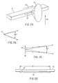
- Lenticular sheets are used to give images an appearance of depth. More specifically, a lenticular sheet comprises a transparent upper layer A having narrow, parallel lenticulas (semi-cylindrical lenses) B on an outer surface, and an image-containing substrate layer C which projects images through the lenticulas. (See FIG. 1A). The two layers of a lenticular sheet provide an image such that different portions of the image are selectively visible as a function of the angle from which the lenticular sheet is viewed. If the image is a composite picture made by bringing together into a single composition a number of different parts of a scene photographed from different angles, and the lenticulas are vertically oriented, each eye of a viewer will see different elements and the viewer will interpret the net result as a three dimensional (3-D) image. The viewer may also move his head with respect to the lenticular sheet thereby observing other views with each eye and enhancing the sense of depth.
- Another method for showing 3-D images is the use of a blocking line screen positioned at a specific distance from the composite picture. This process, known as a parallax process, causes blocking of all images except one specific image. This allows the eyes to view different images as three-dimensional (3-D) images, when the blocking line screen is oriented vertically.
- When the lenticulas or the blocking line screen is oriented horizontally, each eye receives the same image. In this case, the multiple images give illusion of motion when the composite image is rotated about a line parallel to the viewer's eyes. Thus, a simulation of motion is achieved by the process of tipping the lenticular sheet or the blocking line screen, or by movement of the viewer's head to a different angle with respect to the lenticular sheet.
- Whether the lenticulas or the blocking line screen is oriented vertically or horizontally, each of the viewed images is generated by lines of images (also referred to as image lines) which have been interlaced at the spatial frequency of the lenticulas or the blocking line screen. Interlacing lines of each image with other images is referred to as interdigitation. A full set of such interdigitated image lines forms a lenticular image. Interdigitation can be better understood by using an example of four images used to form a composite image with a lenticular sheet that has three lenticulas. In this example, line 1 from each of the four images is in registration with the first lenticula; line 2 from each of the four images is in registration with the second lenticula; etc. Each lenticula is associated with a plurality of image lines D or an image line set (See FIG. 1A), and the viewer sees only one image line of each set with each eye for each lenticula. It is imperative that the image line sets be registered accurately with respect to the lenticulas, so that the proper picture is formed when the assembly is viewed.
- One method of conventional recording of the interdigitated image lines requires recording of the interdigitated image lines on a recording material contained on the substrate layer C and then attaching the substrate layer C to the upper layer A, with the recorded image lines D in precise alignment to the lenticulas B to yield the desired image structure. The precise alignment of the specific lenticulas with the desired image line set during the attachment of the recording material to the lenticular overlay is difficult to achieve. This results in a degraded image quality.
- Conventional recording of lenticular images has been accomplished with a stereoscopic image recording apparatus that uses optical exposure. A light source, such as a halogen lamp, is projected through an original image, via a projection lens, and focused on the substrate layer of the lenticular sheet. The lenticular images are exposed on a recording material as interdigitated image lines. Japanese (Kokoku) Patent Applications Nos. 42-5473, 48-6488, 49-607, and 53-33847 disclose recording apparatus in which two original images are projected for printing on a lenticular recording material. Recording lenticular images in this fashion (i) requires complex projection lens systems, which are expensive, and (ii) does not work well with thermal dye transfer approaches because it requires more power than what is produced by a halogen lamp or a similar light source.
- In contrast, image recording by scanning (linear) exposure requires comparatively simple optics, yet has great flexibility in adapting to various image processing operations, and to alterations in the dimension of the lenticulas. To take advantage of these features, various apparatus and methods have been proposed for recording an image by scanning exposure. For example, Japanese (Kokoku) Patent Application No. 59-3781 teaches a stereoscopic image recording system in which a plurality of original images is taken with a TV camera, processed and stored in frame memories from which the stored image signals are retrieved sequentially as image lines in accordance with the pitch of lenticulas used. After the image lines are recorded on a substrate layer by scanning exposure, the upper layer of the lenticular sheet is bonded to the substrate layer containing the image lines. Another image recording system uses polygon scanners, described in US-A-5,349,419, for exposure of stereoscopic images directly on photosensitive back surface of a lenticular sheet.
- Additionally, US 5,533,152 discloses a method and apparatus for coupling a multi-mode diode laser with an optical fiber. In one embodiment, light emitting from a diode laser is collected by collecting optics. One-half of the light which passes through the collecting optics is passed through a half-wave plate which rotates the polarization of that light which passes through the half-wave plate thereby producing two distinct beams of polarized light. The two beams of light then pass through a Wollaston or Rochon prism which causes the two beams to overlap upon exiting the prism. The exiting light is allowed to enter an optical fiber. In another embodiment, one-half of the light emitted from a laser diode is rotated by a half-wave plate. Both rotated and non-rotated light is then passed through collecting optics and subsequently through a double refractor such that the rotated and non-rotated light is overlapped onto one another and then subsequently inserted into an optical fiber.
- EP 0 560 180 discloses a method and apparatus for recording a stereoscopic image which includes reading a plurality of original images photoelectrically, splitting each original image into linear images of a desired pitch, performing any necessary image processing operations such as arranging the linear images in the recording order, and recording the linear images by scan exposure on a lenticular light-sensitive material having a lenticular sheet and a recording layer. EP 0 533 377 discloses a method of writing a line of image on a photoreceptor with a laser beam in a main scanning direction, and of shifting in a sub-scanning direction to a next main scanning line to write a next line of image which includes a step of shaping the laser beam spot on the photoreceptor in a form of an oval whose the major axis directs in the main scanning direction.
- It is desirable to write interdigitated images directly on a back surface of lenticular sheet using thermal dye transfer. This would eliminate the need for careful alignment of specific pre-printed image lines of the substrate layer with the specific lenticulas of the upper layer of the lenticular sheet The use of thermal dye transfer to write such interdigitated images requires, however, large amounts of energy. Such energy can be provided by high power lasers.
- Furthermore, high quality lenticular images require that a large number of images be placed behind a fine pitched lenticular sheet. For example, in order to produce 25 images with a lenticular sheet of 100 lenticulas per 2.54 cm (=1 inch) one needs to produce 2500 lines per inch of continuous tone spots. This means a pixel size of approximately 10 microns or less. To expose such a small pixel, the beam size has to be approximately of the same size as the pixel size. A single mode laser can easily provide such a small beam size. Therefore, a single mode laser, may be used to write interdigitated images. Unfortunately, high power, inexpensive single mode diode lasers are not available.
Inexpensive high power multimode lasers are commercially available. However, such lasers have two major problems. Firstly, they have an emitting aperture with a high aspect ratio and elliptical beam divergence. These characteristics make it hard to obtain a scanning spot with desired size and shape. Secondly, the emitting aperture size of the laser and hence the spot size at the recording material in any direction is inversely proportional to the amount of laser power in this direction. However, it is desired that a laser thermal printer has a high power density, i.e., that it has both the maximum power and the smallest possible spot size. Because a multimode laser produces a spot size that is long (large spot size in one dimension), the laser power is spread across the length of the spot, resulting in low power density. - It is an object of the present invention to provide a method of printing an image on a lenticular sheet. It is a further object of the present invention to provide an optical printing apparatus. These objects are achieved by the invention as defined in the apended claims.
The above, and other objects, advantages and novel features of the present invention will become more apparent from the accompanying detailed description thereof when considered in conjunction with the following drawings. -
- FIG. 1A illustrates a prior art lenticular sheet.
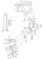
- FIG. 1B is a schematic view of a first embodiment of a flying spot laser thermal printer utilizing several multimode diode lasers and a galvo mirror.
- FIG. 2A is a schematic view of the emitting aperture and the emitted light of a typical multimode laser.
- FIGS. 2B and 2C illustrate a laser beam cone emitted from the emitting aperture of a diode laser. FIG. 2B corresponds to a short dimension of the emitting aperture.
- Figure 2C corresponds to a long dimension of the emitting aperture.
- FIG. 2D illustrates schematically a laser with an emitting aperture comprising an array of small apertures.
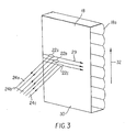
- FIG. 3 shows the orientation of scanning spots on a lenticular sheet.
- FIG. 4 is a perspective schematic view of a printer showing a stage for translating the lenticular sheet (and a thermal donor if a thermal dye transfer method is used) in a cross scan direction.
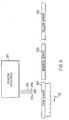
- FIG. 5 illustrates a thermal laser printer exposing a thermal donor with three multimode laser beams.
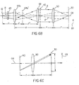
- FIG. 6A is a cross sectional view of the first embodiment in the scan direction.
- FIG. 6B illustrates an imaging system in the scan direction. This figure does not depict either retardation plates nor a Wollaston prism.
- FIG. 6C illustrates how the length of a scan line affects the size of a galvo-mirror.
- FIG. 6D is a schematic cross sectional view of the first embodiment in the cross scan direction, showing gaussian beam propagation.
- FIG. 6E is a schematic cross sectional view of the first embodiment in the cross scan direction. This figure shows that an image of the emitting aperture is formed at the recording medium in the cross scan direction.
- FIG. 6F illustrates a fiber optics segment that is used to reduce beam divergence.
- FIG. 6G is a schematic cross sectional view of the second embodiment in the cross scan direction.
- FIG. 7A shows a beam intensity distribution at an exit pupil of the collecting lens, in the scan direction, when no polarization means are being used to shape the beam.
- FIG. 7B shows the beam intensity distribution at the exit pupil of the collecting lens, in the scan direction, when polarization means are being used to shape the beam.
- FIG. 7C shows a schematic beam intensity distribution at the recording media, in the scan direction.
-
- The present description will be directed in particular to elements forming part of, or in cooperation more directly with, a printer apparatus in accordance with the present invention. It is understood that elements not specifically shown or described may take various forms well known to those skilled in the art.
- FIG. 1B shows the first embodiment of the present invention. In this embodiment the printer apparatus for writing interdigitated image lines on the backs of lenticular sheets comprises three
lasers lasers apertures - FIG. 2A schematically illustrates an emitting
aperture 12 of a typical 1 Watt multimode edge emittingdiode laser 10. Such emitting apertures are typically 100µ long and 1 µ wide. The narrow aperture is a direct result of the manufacturing process. Higher power lasers have longer emitting apertures. For example, a 2 Watt laser will typically have an emitting aperture dimension of 200µ by 1µ. The laser light is usually produced at wavelengths of 700-900 nm. The laser light is typically emitted by the emitting aperture into a cone (as shown in FIG. 2A) of approximately 10° FWHM (Full Width Half Maximum) in by 40° FWHM. The smaller angle (10°) corresponds to the scan direction and the larger angle (40°) corresponds to the cross scan direction. FIGS. 2B and 2C schematically show a greatlyenlarged aperture 12 and illustrate that a larger cone angle corresponds to a small aperture dimension and a smaller cone angle corresponds to a large aperture dimension. The long dimension of the emittingaperture 12 which is shown as a contiguous rectangular aperture on FIG. 2A can be made up as an array of small apertures 12' within the 100 µ by 1 µ area. (See FIG. 2D.) - The Lagrange value H of the laser beam is commonly defined as the product of half the beam size and half the divergence angle. The beam size is defined as half the length of the emitting aperture for a multimode laser and, as FWHM beam waist radius for a single mode laser. A single mode laser has Gaussian beam distribution in both spatial and angular dimensions and a Lagrange value of H = 0.35*λ/π, where λ is the wavelength of the laser beam. Therefore, for a wavelength of 0.83 µ the Lagrange value of a single mode laser is given by
- Typical multimode lasers are available from laser vendors such as Spectro Diode Labs, Inc. located in San Jose, California; Polaroid Co. located in Waltham, Massachusetts; and Semiconductor Laser International Corp. located in Binghamton, New York. A multimode laser behaves like a single mode laser only in the direction perpendicular to the long dimension of the emitting aperture. Thus the Lagrange of the multimode laser in this (short) direction is 0.09 µ.
- The divergence angle of the laser beam is defined by the numerical aperture of the laser beam. In the direction corresponding to the long dimension of the emitting aperture the Lagrange value of the laser beam from a typical 1 Watt multimode laser is given by the product of half the emitting aperture size (i.e., 100µ/2) and the numerical aperture (NA) of the laser beam in this direction. Because the numerical aperture NA of the laser beam in this direction is 0.14, the Lagrange value is given by
- This value is much larger than the Lagrange value for the single mode laser and thus we refer to the emission in this direction as multimode emission. It is well known that the number of resolvable spots of a flying spot laser printer along the scan line is inversely proportional to the Lagrange value of the scanning laser beam. This is why flying spot laser printers, invariably use single mode lasers which have the smallest Lagrange value. However, as mentioned above, high power single mode lasers are expensive.
- According to one aspect of this invention, the printing of the lenticular images on the back surface of the
lenticular sheet 18 is done with flying spotlaser printer apparatus 20 in such manner that the fast scan direction corresponds to the direction of the long dimension of the emitting aperture(s) 12a, 12b, 12c. That is, thescanning spots scanning laser beams lenticulas 18a per inch, which limits the total number of resolvable spots for each viewed image to a couple of hundreds for an image size on the order a few inches. Becausemany image lines 25 respond to each lenticula, the image lines must be narrow and closely spaced, requiring higher resolution. It is preferred that the size of thescanning spots - Due to the unusual requirements of the lenticular images, namely, the need for a small spot only in the cross scan direction and the ability to tolerate a larger spot size in the fast scan direction, it is possible to utilize multimode diode lasers instead of more expensive single mode lasers.
- As discussed above and shown in FIGS. 1B and 3, the
multimode diode lasers scan direction 29 of the laser beams corresponds to the long dimension of the emittingapertures scanning spots scanning laser beams narrow lines 25 with width of 10µ or less on therecording material 30. Therecording material 30 may be, for example, a back surface of a lenticular sheet and a thermally activated donor. Although thermal dye transfer method is preferred, actinically exposed material, such as silver halide, can also be used as arecording material 30 if visible light lasers are utilized. If an actinically exposed material is being used, a thermal donor is not needed. - During the scanning action the
lasers laser beams - The
recording material 30 is advanced, as shown by avertical arrow 32 on FIG. 3, in the slow scan (cross scan) direction so narrow line spacings are being made, thereby abutting the image lines. The scanning function may be accomplished by any scanner, for example a galvo-mirror 40 (FIG. 1B), spinning hologon, or a spinning polygon mirror 40' such as the one depicted in FIG. 4. Thelaser beams recording material 30 with ascan lens 50, for example, an f- lens shown in FIG. 1B. Such a scan lens may be made of refractive and/or reflective component(s). - In order to use scanning
multimode laser beams recording material 30 is translated by adriver 46 relative to thescanning laser beam 24. If therecording material 30 includes athermal donor thermal donor 52A is removed and the process repeated with two newthermal donors - As described above,
laser beams multimode lasers imaging system 60 of theprinter 20 reduces the divergence of the laser beams in the cross scan direction and providesscanning spots recording media 30. Theimaging system 60 includesoptical components collection lenses field lens 68 and thescan lens 50. These components are depicted in FIGS. 1B and 6A. - The
optical components corresponding lasers - Behind the
optical components spherical collection lenses collection lenses - According to one aspect of the present invention, a portion of each
laser beam collection lenses retardation waveplates - Thus, one half of each of the
laser beams respective collection lens collection lenses waveplates galvo mirror deflector 40. Before thelaser beams 24 reach the galvo mirror they pass through thefield lens 68 and aWollaston prism 69. TheWollaston prism 69 overlaps different portions of each of thelaser beams field lens 68, theWollaston prism 69 and the waveplates, 65a, 65b or 65c is provided later on in the specification. After being scanned by the galvo mirror, the scanning beams pass through thescan lens 50 and impinge on therecording material 30. - There are two approaches in constructing an imaging system of a flying spot printer. The first approach requires that the emitting aperture of a laser be optically conjugated by the imaging system to the recording material. This means that the image of the emitting aperture is formed at the recording material. If this approach is used, non-uniformities, hot spots or segmentation of the emitting aperture will affect the scanning spot quality and artifacts may be produced on the print.
- In the second approach, the far field of the laser located at the exit pupil of the
lens recording material 30. This is the approach utilized in constructing theimaging system 60, of this embodiment of the present invention, in the direction that corresponds to a scan direction. (See FIG. 6B) In the direction corresponding to the scan direction the exit pupil 64' of thelens 64 is located at the back focal plane of thelens 64. Thus, in this direction the image of theexit pupil 64a', 64b' or 64c' of the collectinglens recording material 30, so that the source (emitting aperture) appears infinitely far away to an observer situated at the recording material. This approach is preferred because the spot at the recording material is not the image of the emitting aperture. Therefore, non-uniformities, hot spots or segmentation in the long dimension of the emitting aperture will not result in artifacts and will not effect the quality of the image. - FIG. 6B illustrates that the
scan lens 50 is positioned so as to focus collimated rays A (exiting the field lens 68) on therecording material 30 and to collimate the rays B crossing the optical axis OA at the intermediate image plane, i.e.,galvo mirror 40. The focal length requirements of thescan lens 50 and the required length ℓ of the scan line (see FIG. 6C) at therecording material 30, determine the size of thegalvo mirror 40. For example, if the focal length f of thescan lens 50 is 112 mm, and this scan lens is located at a distance of 112mm away from the recording material and from the galvo-mirror, than the galvo-mirror dimensions are 12mm by 12mm. (See FIG. 6C) Since the length of the emittingaperture 12 of thelaser 10 is known (it is 0.1 mm) and its image size on the galvo-mirror 40 is also known (it is 12 mm), the magnification m provided by thelenses lens lens galvo mirror 40. If thelens lenses galvo mirror 40. - The
laser beams multimode lasers 10a, 10b are directed to overlap at thegalvo mirror 40. (See FIGS. 1B and 6A) Thefield lens 68 is situated proximate to the galvo-mirror 40. The focal length f" of thefield lens 68 approximately equals to the distance d (i.e., f"≈d ≈552mm). Therefore, in the scan direction, thisfield lens 68 collimates the light rays going through the centers of thecollection lenses scan lens 50 and are focused by thescan lens 50 on the recordingmedia material plane 30. Thus, in the scan direction, therecording material 30 is conjugated to theexit pupils 64a', 64b', and 64c' of thecollection lenses spots 22a, 22b at therecording material 30 correspond to the beam profiles at theexit pupils 64a', 64b' oflens - FIG. 6D shows another schematic cross sectional view of the printer according to the first embodiment of the present invention. This view depicts the printer in a cross scan direction and shows that the recording medium is conjugated to the emitting apertures in the cross scan direction.
- It is noted that we are conjugating the emitting aperture to the medium in the geometrical optics sense. (See FIG. 6E). However, gaussian beam properties apply because we are using laser beams.
- In the direction corresponding to a cross scan direction the laser 10 (only one shown) is essentially a single mode laser. As shown in FIG. 2A, in this direction the
laser beam 24 is diverging at a large angle. An anamorphic optical system, such as a cylinder or toroidaloptical component 63 is placed close to thelaser 10 in order to reduce this divergence. Theoptical component 63 can be a fiber optics segment (see FIG. 6F) used as a cylinder lens, or a gradient fiber such as the one made by Doric Inc. of Ancienne-Lorette, PQ Canada, or by Blue Sky Research of Santa Cruz, California. The focal length of thisoptical component 63 determines the beam size at thegalvo mirror 40. The shorter it is, the smaller is the beam size (in this direction) at the exit pupil ofcollection lens 64 and thus the bigger is the beam size at the galvo-mirror. It is noted that in the cross scan direction thecollection lens component 64 does not create the image the emitting aperture at the plane of the galvo-mirror. Instead thescan lens 50 forms an image of the emitting aperture at the recording material. Thus, in the cross scan direction the emitting aperture and the recording media are conjugated. - By proper choice of the focal length for the
lens component 64 it is possible to match the beam size at thegalvo mirror 40 to the size of the galvo-mirror. That is, the beam size at the galvo-mirror 40 and the size of the galvo-mirror should be preferably equal or approximately equal to one another. The beam size at the galvo-mirror 40 in this direction is inversely proportional the size of thespot 22 at therecording material 30. Thus a large beam at the galvo is desired. However, too large a beam will be truncated by the galvo-mirror. - For example, the
lens component 64 may have the focal length of 110 microns. The cross scan beam size of thelaser beam 24 at the FWHM of 65 microns. Thislaser beam 24 is shaped bylens component 63 in the cross scan direction so that the laser beam's FWHM waist diameter is about 25 microns. This laser beam diverges over the distance d = 552mm to the galvo of 552 and has FWHM size there of 7.7 mm. The loss at the galvo-mirror due to truncation is about 7.2%. The spot size at therecording material 30, as the laser beam is diffracted by thescan lens 50, is about 14 microns FWHM. - Thus, with one cylinder lens 63 (for each of the laser beams), the control of the beam size in the cross scan direction is accomplished. The size of the
beams galvo mirror 40 is matched by thecylinder lens 63 to the size of the galvo mirror, so that these sizes are approximately the same (i.e., no more than 15% and preferably 10% or smaller difference). This solution assumes that the deviations in the emitting aperture size in the cross scan beam direction are small. This is not always true and some means for compensation of these variations maybe needed. Lasers from the same production batch may have similar but larger then typical divergence angle in the cross scan direction. This can be remedied by employing additional lenses. For example, FIG. 6G shows one or more movable cylindrical lens elements 66 are placed in the optical path betweenlenses field lens 68 to act as a zoom system and to control the beam size of the laser beam in the cross scan direction. - Without the
retardation plates Wollaston prism 69 the energy distribution is thescan direction 29 is approximately Gaussian, as shown in FIG. 7A. In order for efficient dye transfer to occur, a scanning spot with a high density, fairly uniform energy distribution is needed. Thus, a flat top energy distribution is preferred and, the spot size should be of the smallest dimension possible. - According to one aspect of the invention, the shapes of the scanning spots are modified by polarizing optics, such as (½ wave) retardation plates and the
Wollaston prism 69, so that the intensity distribution is approximately rectangular in shape and, the size of scanning spots is reduced. FIG. 6A illustrates the cross sectional view of theimaging system 60 of the flying spot printer in the plane parallel to the scan direction. Although more than two multimode lasers may be used this figure depicts only twolasers 10a and 10b. Thelaser beams multimode lasers 10a and 10b are collected bylenses galvo mirror 40. Thelaser beams - FIG. 7A shows the P polarized beam entering the
exit pupil 64a' or 64b' oflens lenses retardation plate retardation plates - The
beams multimode lasers 10a, 10b overlap at the galvo-mirror 40. TheWollaston prism 69 is located proximate to the galvo-mirror 40. TheWollaston prism 69 overlaps the S polarized portion of the beam onto the P polarized portion of the beam, creating a concentrated laser beam. The effect of this overlap on the spot shape at the recording material is shown on FIG. 7C. The result is a higher beam density and a more narrow, smoother, approximately rectangular beam intensity profiles. Without theWollaston prism 69 and theretardation plates recording material 30 would have been of the shape shown in FIG. 7A. The beam intensity shown on FIG. 7C is better for thermal printing because it is of higher power density as measured in Watts/CM^2. Laser printing typically has a threshold level as shown on FIG. 7A and 7C. Light under the threshold does not contribute to the printing and is lost. A rectangular energy distribution within the spot minimizes this loss.
Claims (6)
- A method of printing an image on a lenticular sheet having lenticulas, said lenticulas having a linear axis defining a length of the lenticulas , with a printer that has a scanner and that utilizes a polarized multimode laser beam provided by an emitting aperture of a multimode laser, said method comprising the steps of:providing a printer having a scanning element (40) having a fast scan direction and a slow scan direction and a multimode laser (10) emitting a multimode laser beam, said multimode laser having an emitting aperture (12) that has a long cross section and a short cross section;changing polarization of a portion of said multimode laser beam, so that said multimode laser beam comprises a first portion with one polarization and a second portion with a different polarization;at least partially superimposing said first portion of said multimode laser beam onto said second portion of said multimode laser beam, thereby forming a superimposed laser beam;forming a printing spot with said superimposed laser beam;scanning said superimposed laser beam along a scan line across said lenticular sheet material, so that said fast scan direction corresponds to said long cross section of the emitting aperture and is along the length of the lenticulas; andtranslating the lenticular sheet in a direction perpendicular to the length of the lenticulas.
- An optical printing apparatus (20; 60) comprising:a multimode laser (10) adapted to provide a multimode laser beam along a path;a scanning element (40) having a fast scan direction and a cross scan direction ;a scanning lens (50) providing at least one spot at a recording media (30);imaging optics (64,68); characterized byat least one polarization changing component (65) partially intercepting said path to change polarization of laser light intercepted by said component, so that a multimode laser beam provided along said path has a cross section with two portions of differing polarization;a polarization combiner (69) overlapping said two portions of said multimode laser beam, thereby forming a concentrated laser beam;said scanning element (40) being arranged to scan said concentrated laser beam, said scanning element being proximate to said polarization combiner;said scanning lens (50) intercepting said concentrated laser beam scanned by said scanning element;said laser having an emitting aperture (12) that has a long cross section and a short cross section, said long cross section corresponding to a fast scan direction, and said short cross section corresponding to a cross scan direction; andsaid imaging optics (64, 68) forming an image of said emitting aperture on said scanning element in at least one cross section.
- An optical apparatus according to claim 2, wherein said polarization changing component (65) is a retardation plate.
- An optical apparatus according to claim 2, wherein said polarization combiner (69) is a Wollaston prism.
- An optical apparatus according to claim 2, further comprising an anamorphic lens (63) with an optical power that is stronger in a cross scan direction than in a scan direction, said anamorphic lens decreasing divergence of said multimode laser beam in said cross scan direction.
- An optical apparatus according to claim 2, said optical apparatus comprising a plurality of multimode lasers (10a, 10b, 10c) and wherein(i) said imaging optics includes a plurality of collection lenses (64a, 64b, 64c), each of said collection lenses corresponding to one of said multimode lasers; and(ii) said emitting aperture (12) being optically conjugated to a recording material in a cross-scan direction and an exit pupil of each of said collection lens (64a, 64b, 64c) is being optically conjugated to the recording material in a scan direction.
Applications Claiming Priority (2)
| Application Number | Priority Date | Filing Date | Title |
|---|---|---|---|
| US175735 | 1998-10-20 | ||
| US09/175,735 US6191802B1 (en) | 1998-10-20 | 1998-10-20 | Optical apparatus and method for increasing intensity of multimode laser beams and a printer for printing lenticular images utilizing such laser beams |
Publications (3)
| Publication Number | Publication Date |
|---|---|
| EP0996022A2 EP0996022A2 (en) | 2000-04-26 |
| EP0996022A3 EP0996022A3 (en) | 2000-08-30 |
| EP0996022B1 true EP0996022B1 (en) | 2003-08-13 |
Family
ID=22641422
Family Applications (1)
| Application Number | Title | Priority Date | Filing Date |
|---|---|---|---|
| EP99203281A Expired - Lifetime EP0996022B1 (en) | 1998-10-20 | 1999-10-07 | Optical apparatus and method for increasing intensity of multimode laser beams and a printer for printing lenticular images utilizing such laser beams |
Country Status (4)
| Country | Link |
|---|---|
| US (1) | US6191802B1 (en) |
| EP (1) | EP0996022B1 (en) |
| JP (1) | JP4767380B2 (en) |
| DE (1) | DE69910326T2 (en) |
Families Citing this family (22)
| Publication number | Priority date | Publication date | Assignee | Title |
|---|---|---|---|---|
| ATE441130T1 (en) * | 2000-11-03 | 2009-09-15 | Microvision Inc | GRID DISPLAY WITH SWITCHED FEED AND DISTORTION CORRECTION |
| US6781691B2 (en) * | 2001-02-02 | 2004-08-24 | Tidal Photonics, Inc. | Apparatus and methods relating to wavelength conditioning of illumination |
| EP1656584A2 (en) * | 2003-07-16 | 2006-05-17 | Tidal Photonics, Inc. | Apparatus and methods relating to concentration and shaping of illumination |
| EP1709474A4 (en) * | 2003-09-26 | 2010-01-06 | Tidal Photonics Inc | Apparatus and methods relating to color imaging endoscope systems |
| US7544163B2 (en) * | 2003-09-26 | 2009-06-09 | Tidal Photonics, Inc. | Apparatus and methods relating to expanded dynamic range imaging endoscope systems |
| CA2581735A1 (en) * | 2003-09-26 | 2005-04-07 | Tidal Photonics, Inc. | Apparatus and methods relating to enhanced spectral measurement systems |
| US7406391B2 (en) * | 2004-09-20 | 2008-07-29 | Affymetrix, Inc. | System, method, and computer product for detection instrument calibration |
| US20080260242A1 (en) * | 2006-06-22 | 2008-10-23 | Tidal Photonics Inc. | Apparatus and methods for measuring and controlling illumination for imaging objects, performances and the like |
| DE102006050155B4 (en) * | 2006-10-21 | 2016-06-09 | Keming Du | Arrangements for shaping laser beams |
| DE102008008232B4 (en) | 2008-02-08 | 2011-04-14 | Realeyes Gmbh | Apparatus and method for exposing a photographic material |
| US8374818B2 (en) * | 2008-12-19 | 2013-02-12 | Affymetrix, Inc. | System, method and apparatus for calibrating inspection tools |
| US9767342B2 (en) | 2009-05-22 | 2017-09-19 | Affymetrix, Inc. | Methods and devices for reading microarrays |
| NL2004481C2 (en) * | 2010-03-31 | 2011-10-04 | Sagem Identification B V | METHOD FOR PRODUCING A THREE-DIMENSIONAL IMAGE BASED ON CALCULATED IMAGE ROTATIONS. |
| US9024991B2 (en) * | 2012-05-28 | 2015-05-05 | Nidec Copal Corporation | Laser marker |
| JP6127714B2 (en) * | 2013-05-23 | 2017-05-17 | セイコーエプソン株式会社 | Laser projector |
| CN103447693A (en) * | 2013-07-18 | 2013-12-18 | 上海电机学院 | Method for manufacturing micrometer and nanometer composite periodic structure |
| US9599572B2 (en) * | 2014-04-07 | 2017-03-21 | Orbotech Ltd. | Optical inspection system and method |
| CN105467609B (en) * | 2016-01-15 | 2017-12-15 | 南开大学 | A kind of the reference light beam-splitting method and its special purpose device of the spatially angular multiplexing holography based on Wollaston prism |
| US10241292B2 (en) | 2016-12-09 | 2019-03-26 | Bae Systems Information And Electronic Systems Integration Inc. | Ultra-fast and mechanically stable zoom lens |
| KR102045476B1 (en) * | 2018-06-28 | 2019-11-15 | 옵티시스 주식회사 | Optical connector |
| CN112666196A (en) * | 2019-10-16 | 2021-04-16 | 北航(四川)西部国际创新港科技有限公司 | Ray integration device |
| JP2021174739A (en) * | 2020-04-30 | 2021-11-01 | 船井電機株式会社 | Light projection device and light projection device for vehicle |
Citations (1)
| Publication number | Priority date | Publication date | Assignee | Title |
|---|---|---|---|---|
| EP0533377A2 (en) * | 1991-09-18 | 1993-03-24 | Konica Corporation | Image forming method |
Family Cites Families (14)
| Publication number | Priority date | Publication date | Assignee | Title |
|---|---|---|---|---|
| DE364549C (en) | 1914-03-24 | 1922-11-27 | Christian Meyer | Comb cleaner |
| JPS49607A (en) | 1972-04-21 | 1974-01-07 | ||
| AT364549B (en) * | 1976-03-13 | 1981-10-27 | Heidenhain Gmbh Dr Johannes | ARRANGEMENT WITH A LASER AND OPTICAL MEANS TO EXPAND THE LASER BEAM IN A PLANE |
| JPS5333847A (en) | 1976-09-06 | 1978-03-30 | Matsushita Electric Works Ltd | Pruner |
| JPS593781A (en) | 1982-06-30 | 1984-01-10 | Fujitsu Ltd | Static semiconductor storage device |
| JPH0627904B2 (en) * | 1986-02-06 | 1994-04-13 | 旭光学工業株式会社 | Laser beam scanning optics |
| JP2746790B2 (en) | 1992-03-02 | 1998-05-06 | 富士写真フイルム株式会社 | Stereoscopic image recording method and stereoscopic image recording apparatus |
| JPH05289208A (en) | 1992-04-15 | 1993-11-05 | Fuji Photo Film Co Ltd | Method and device for recording stereoscopic image |
| JPH0822091A (en) * | 1994-07-05 | 1996-01-23 | Canon Inc | Stereoscopic image recording method and its device and stereoscopic image forming body |
| JP3546898B2 (en) * | 1995-01-30 | 2004-07-28 | セイコーエプソン株式会社 | Optical scanning device |
| US5633736A (en) * | 1995-03-28 | 1997-05-27 | Eastman Kodak Company | Scan lens and an optical scanner system incorporating two deflectors |
| US5533152A (en) * | 1995-05-02 | 1996-07-02 | Eastman Kodak Company | Method and apparatus for coupling light emitted from a multi-mode laser diode array to a multi-mode optical fiber |
| US5808657A (en) * | 1996-06-17 | 1998-09-15 | Eastman Kodak Company | Laser printer with low fill modulator array and high pixel fill at a media plane |
| EP0867991B1 (en) | 1997-03-27 | 2001-05-30 | Mitsui Chemicals, Inc. | Semiconductor laser light source and solid-state laser apparatus |
-
1998
- 1998-10-20 US US09/175,735 patent/US6191802B1/en not_active Expired - Lifetime
-
1999
- 1999-10-07 DE DE69910326T patent/DE69910326T2/en not_active Expired - Lifetime
- 1999-10-07 EP EP99203281A patent/EP0996022B1/en not_active Expired - Lifetime
- 1999-10-13 JP JP29155099A patent/JP4767380B2/en not_active Expired - Fee Related
Patent Citations (1)
| Publication number | Priority date | Publication date | Assignee | Title |
|---|---|---|---|---|
| EP0533377A2 (en) * | 1991-09-18 | 1993-03-24 | Konica Corporation | Image forming method |
Also Published As
| Publication number | Publication date |
|---|---|
| US6191802B1 (en) | 2001-02-20 |
| DE69910326D1 (en) | 2003-09-18 |
| EP0996022A3 (en) | 2000-08-30 |
| DE69910326T2 (en) | 2004-06-09 |
| JP4767380B2 (en) | 2011-09-07 |
| JP2000121974A (en) | 2000-04-28 |
| EP0996022A2 (en) | 2000-04-26 |
Similar Documents
| Publication | Publication Date | Title |
|---|---|---|
| EP0996022B1 (en) | Optical apparatus and method for increasing intensity of multimode laser beams and a printer for printing lenticular images utilizing such laser beams | |
| US5105299A (en) | Unfolded optics for multiple row deformable mirror device | |
| US5311349A (en) | Unfolded optics for multiple row spatial light modulators | |
| EP0712032B1 (en) | Lenticular recording material | |
| EP0604077B1 (en) | Multiple beam diode laser output scanning system | |
| US6177217B1 (en) | Method and apparatus for precise positioning of arrays with periodic structures | |
| JP3248604B2 (en) | Method and apparatus for making a print including parallax information | |
| US5956070A (en) | Color xerographic printer with multiple linear arrays of surface emitting lasers with dissimilar polarization states and dissimilar wavelengths | |
| US6252621B1 (en) | Printing lenticular images | |
| JPH02115814A (en) | Light beam scanning device | |
| US6069680A (en) | Flying spot laser printer apparatus and a method of printing suitable for printing lenticular images | |
| US6456435B1 (en) | Method and apparatus for adjusting spot size of one color component of a multiple color co-axial laser beam | |
| JPH06109993A (en) | Raster output scanner | |
| US6200713B1 (en) | Method and apparatus for locating arrays with periodic structures relative to composite images | |
| US5995132A (en) | Method and apparatus for printing interdigitated images | |
| JPH05221013A (en) | Multibeam laser printer | |
| EP0782928B1 (en) | Color xerographic printer with multiple linear arrays of surface emitting lasers with the same wavelengths | |
| EP0040716A1 (en) | Image multiplexing device | |
| JP5021011B2 (en) | Printing lenticular images | |
| JPS5968723A (en) | Optical modulating element | |
| JPH0258014A (en) | Optical scanner | |
| EP0781663B1 (en) | Color xerographic printer with multiple linear arrays of surface emitting lasers with dissimilar wavelengths | |
| JPH0192772A (en) | Multibeam laser scanner | |
| JPS6017716A (en) | Laser beam printer optical system | |
| JPH04255818A (en) | Optical recorder |
Legal Events
| Date | Code | Title | Description |
|---|---|---|---|
| PUAI | Public reference made under article 153(3) epc to a published international application that has entered the european phase |
Free format text: ORIGINAL CODE: 0009012 |
|
| AK | Designated contracting states |
Kind code of ref document: A2 Designated state(s): DE FR GB |
|
| AX | Request for extension of the european patent |
Free format text: AL;LT;LV;MK;RO;SI |
|
| PUAL | Search report despatched |
Free format text: ORIGINAL CODE: 0009013 |
|
| AK | Designated contracting states |
Kind code of ref document: A3 Designated state(s): AT BE CH CY DE DK ES FI FR GB GR IE IT LI LU MC NL PT SE |
|
| AX | Request for extension of the european patent |
Free format text: AL;LT;LV;MK;RO;SI |
|
| RIC1 | Information provided on ipc code assigned before grant |
Free format text: 7G 02B 27/28 A, 7G 02B 27/22 B, 7B 41M 3/06 B, 7G 02B 27/09 B, 7H 04N 1/23 B |
|
| 17P | Request for examination filed |
Effective date: 20010125 |
|
| 17Q | First examination report despatched |
Effective date: 20010330 |
|
| AKX | Designation fees paid |
Free format text: DE FR GB |
|
| GRAH | Despatch of communication of intention to grant a patent |
Free format text: ORIGINAL CODE: EPIDOS IGRA |
|
| GRAH | Despatch of communication of intention to grant a patent |
Free format text: ORIGINAL CODE: EPIDOS IGRA |
|
| GRAA | (expected) grant |
Free format text: ORIGINAL CODE: 0009210 |
|
| AK | Designated contracting states |
Designated state(s): DE FR GB |
|
| REG | Reference to a national code |
Ref country code: GB Ref legal event code: FG4D |
|
| REF | Corresponds to: |
Ref document number: 69910326 Country of ref document: DE Date of ref document: 20030918 Kind code of ref document: P |
|
| ET | Fr: translation filed | ||
| PLBE | No opposition filed within time limit |
Free format text: ORIGINAL CODE: 0009261 |
|
| STAA | Information on the status of an ep patent application or granted ep patent |
Free format text: STATUS: NO OPPOSITION FILED WITHIN TIME LIMIT |
|
| 26N | No opposition filed |
Effective date: 20040514 |
|
| PGFP | Annual fee paid to national office [announced via postgrant information from national office to epo] |
Ref country code: GB Payment date: 20120925 Year of fee payment: 14 |
|
| PGFP | Annual fee paid to national office [announced via postgrant information from national office to epo] |
Ref country code: FR Payment date: 20121010 Year of fee payment: 14 |
|
| GBPC | Gb: european patent ceased through non-payment of renewal fee |
Effective date: 20131007 |
|
| PG25 | Lapsed in a contracting state [announced via postgrant information from national office to epo] |
Ref country code: GB Free format text: LAPSE BECAUSE OF NON-PAYMENT OF DUE FEES Effective date: 20131007 |
|
| REG | Reference to a national code |
Ref country code: FR Ref legal event code: ST Effective date: 20140630 |
|
| PG25 | Lapsed in a contracting state [announced via postgrant information from national office to epo] |
Ref country code: FR Free format text: LAPSE BECAUSE OF NON-PAYMENT OF DUE FEES Effective date: 20131031 |
|
| PGFP | Annual fee paid to national office [announced via postgrant information from national office to epo] |
Ref country code: DE Payment date: 20141028 Year of fee payment: 16 |
|
| REG | Reference to a national code |
Ref country code: DE Ref legal event code: R119 Ref document number: 69910326 Country of ref document: DE |
|
| PG25 | Lapsed in a contracting state [announced via postgrant information from national office to epo] |
Ref country code: DE Free format text: LAPSE BECAUSE OF NON-PAYMENT OF DUE FEES Effective date: 20160503 |