EP0996090A2 - Verfahren zur Verarbeitung eines Eingangsbildes - Google Patents
Verfahren zur Verarbeitung eines Eingangsbildes Download PDFInfo
- Publication number
- EP0996090A2 EP0996090A2 EP99203395A EP99203395A EP0996090A2 EP 0996090 A2 EP0996090 A2 EP 0996090A2 EP 99203395 A EP99203395 A EP 99203395A EP 99203395 A EP99203395 A EP 99203395A EP 0996090 A2 EP0996090 A2 EP 0996090A2
- Authority
- EP
- European Patent Office
- Prior art keywords
- image
- values
- detail
- value
- modification
- Prior art date
- Legal status (The legal status is an assumption and is not a legal conclusion. Google has not performed a legal analysis and makes no representation as to the accuracy of the status listed.)
- Withdrawn
Links
- 238000000034 method Methods 0.000 title claims abstract description 17
- 238000012545 processing Methods 0.000 title claims description 13
- 230000004048 modification Effects 0.000 claims abstract description 22
- 238000012986 modification Methods 0.000 claims abstract description 22
- 210000000056 organ Anatomy 0.000 claims description 13
- 230000015654 memory Effects 0.000 claims description 12
- 238000006243 chemical reaction Methods 0.000 claims description 7
- 230000003247 decreasing effect Effects 0.000 claims description 3
- 230000008569 process Effects 0.000 claims description 3
- 238000003384 imaging method Methods 0.000 claims 2
- 230000001419 dependent effect Effects 0.000 abstract description 4
- 238000000354 decomposition reaction Methods 0.000 description 13
- 238000001914 filtration Methods 0.000 description 8
- 238000010586 diagram Methods 0.000 description 6
- 210000004072 lung Anatomy 0.000 description 5
- 210000003484 anatomy Anatomy 0.000 description 3
- 230000005855 radiation Effects 0.000 description 3
- 238000001228 spectrum Methods 0.000 description 3
- 230000005540 biological transmission Effects 0.000 description 2
- 238000012937 correction Methods 0.000 description 2
- 230000000694 effects Effects 0.000 description 2
- 210000001370 mediastinum Anatomy 0.000 description 2
- OAICVXFJPJFONN-UHFFFAOYSA-N Phosphorus Chemical compound [P] OAICVXFJPJFONN-UHFFFAOYSA-N 0.000 description 1
- 240000007509 Phytolacca dioica Species 0.000 description 1
- 101100289792 Squirrel monkey polyomavirus large T gene Proteins 0.000 description 1
- 210000001015 abdomen Anatomy 0.000 description 1
- 230000008901 benefit Effects 0.000 description 1
- 210000000746 body region Anatomy 0.000 description 1
- 230000008859 change Effects 0.000 description 1
- 230000007423 decrease Effects 0.000 description 1
- 238000013461 design Methods 0.000 description 1
- 238000011161 development Methods 0.000 description 1
- 238000003745 diagnosis Methods 0.000 description 1
- 230000006870 function Effects 0.000 description 1
- 230000006872 improvement Effects 0.000 description 1
- 239000011159 matrix material Substances 0.000 description 1
- 238000005259 measurement Methods 0.000 description 1
- 230000001575 pathological effect Effects 0.000 description 1
- 210000001147 pulmonary artery Anatomy 0.000 description 1
- 230000009467 reduction Effects 0.000 description 1
- 238000007789 sealing Methods 0.000 description 1
- 230000001629 suppression Effects 0.000 description 1
- 230000003313 weakening effect Effects 0.000 description 1
Images


Classifications
-
- G06T5/75—
-
- G—PHYSICS
- G06—COMPUTING; CALCULATING OR COUNTING
- G06T—IMAGE DATA PROCESSING OR GENERATION, IN GENERAL
- G06T5/00—Image enhancement or restoration
- G06T5/20—Image enhancement or restoration by the use of local operators
Definitions
- the input image can be an X-ray, but others can also images generated in medical diagnostics and available in electronic form are processed, each pixel (a pixel is a picture element; an image is composed of a matrix of pixels) the brightness in this pixel characteristic image value is assigned.
- the invention also relates to a Arrangement to carry out this procedure.
- a method of the type mentioned is known from EP-A 527 525.
- the input image of a Undergo low pass filtering, and the resulting low pass image becomes from the input image subtracted, resulting in a difference image referred to as the first detail image, in which only the very highest spatial frequencies of the input image are preserved.
- the first detail image in which only the very highest spatial frequencies of the input image are preserved.
- the Subtraction of the low-pass image from the input image can differ for pixels in the Detail picture result in both positive and negative values. These represent the contrast of the Picture; however, in the following they are nevertheless referred to as image values.
- the low-pass image is a new low-pass filtering subjected so that a second low-pass image is created, which is based on the original image represents less high-frequency spatial frequency components than the first low-pass image.
- the second low-pass image is subtracted from the first, producing a second detail image, the mainly represents spatial frequencies that are below the spatial frequency band of first detail image, but above the spatial frequency range of the second low-pass image lie.
- the second low-pass image is used in an analogous manner third low-pass image with even less high-frequency spatial frequency components and an off the third detail image derived from the difference between the second and third low-pass image is generated.
- the spatial frequency band represented by this third detail picture lies predominantly below the spatial frequency range of the second detail image, but above the Spatial frequency range of the third low-pass picture.
- Connect to this third decomposition level other levels of decomposition, with the resulting derail images always represent lower spatial frequencies than the detail image of the previous one Decomposition level.
- the detail images and the residual image are added after at least one of the Detail pictures has been modified. This is supposed to be the diagnostically relevant Image information highlighted and those that are unimportant or disruptive for the diagnosis Image information can be suppressed.
- the object of the present invention is to provide a method of the type mentioned at the outset shape that the image quality can be further improved.
- This task will solved according to the invention in that the modification of an image value of the multiplication corresponds to this image value with a factor that both of this image itself and also from the average image value and / or the variation of the image values in a window depends on the respective pixel in the input image or an image derived therefrom.
- the invention is based on the knowledge that optimal image quality can only be achieved can result if the modification of the image values both from the respective image value itself as well as the average image value and / or the variation of the image values in one Window around the respective pixel in the input image or an image derived from it depends.
- This makes it possible, for example, for the low values in a detail picture Image values in relation to the higher image values are then enhanced when they are Assigned pixels that lie in a dark area of the image and are not amplified, if the pixel in question lies in a bright area of the image.
- the invention is further based on the finding that the modification instead of mean image value (which is equivalent to the density of the image) in a window around the pixel in question also from the variation of the image values in such Window can hang - at least when it comes to the noise at the Contrast enhancement not visible. In image areas where the image values vary greatly, the noise is not perceived as strongly as in the Image areas in which there is only a slight variation in the image values.
- One way to implement the invention would be to To provide table memory in which for each image value of a pixel and for each density (average image value) a factor is stored in a window by this pixel.
- storing such a double dependency in a table memory would be complex, and changes to this double dependency would only be with to implement extraordinary effort.
- a particularly simple type of control is specified in claim 3.
- the Weighting of the density (the average image value) and / or the variation of the Image values in the window around the pixel in the original image or a derived image depends. If the detail screen has a weighting factor of 1 and before the conversion the detail image is weighted with a weighting factor of 0 after the conversion, the total image contains no contrast enhancement. However, if the detail picture before Conversion with a weighting factor of 0 and the detail screen after the conversion with a weighting factor of 1, the full contrast increase is obtained. It is equivalent to (pixel by pixel) the image values of the detail image before and after the Subtract conversion from each other and not weight the difference to that add converted detail image.
- Claim 4 describes a suitable for the suppression of noise Continuing education, which assumes that the major part of the noise relates to the first detail picture with the highest spatial frequencies and possibly also on the second detail picture concentrated. If with decreasing density and increasing variation of the image values the weak contrast boost is reduced, the noise in the for it sensitive image areas (bright image areas or image areas with low variation the image values or high spatial frequencies) are not raised.
- the extent of the image improvement depends on the probability that Image signal and not to amplify the noise, or the probability that possibly masked noise is masked.
- the advantage of this type of noise-resistant Image enhancement is that there is no weakening of original image content.
- Claim 5 describes a device for performing the method according to the invention.
- the further embodiment according to claim 6 relates to an X-ray system with a memory arrangement (database) in which a set of recording parameters is stored for a number of organs.
- database a memory arrangement
- X-ray systems such databases are known under the term "GSP '(A natomically P rogrammed R adiography) per se since long. It is based on the knowledge that there is no setting of the recording parameters that is optimal for the recording of all organs.
- Fig. 1, 1 denotes an X-ray emitter which emits a beam 2, which one not shown, on one indicated by a table top 3 Patients on the patient table are irradiated and placed on an image sensor 4 that hits the incident X-ray intensity in electrical signals, depending on the ons implements.
- the image sensor 4 can, for example, consist of a multiplicity of matrices arranged, X-radiation sensitive detector elements, which generate electrical signals, the amplitude of the intensity of the incident on them X-ray radiation.
- the image sensor can also be a photoconductor contain, on which a charge pattern dependent on the X-radiation is generated, which is scanned electrosratically.
- an image sensor can also be a Storage phosphor can be provided in which a latent image by the X-rays is generated, which can be read out and digitized by means of a laser.
- the concrete physical design of the image sensor is not for the invention essential; it is only important that the x-ray image is converted into a sequence of digital Data words can be implemented, the image values at the individual pixels of a Represent input image.
- the image sensor 4 is read by a reader 5 adapted to it, the one Sequence of digital values generated, each an image value of the input image correspond.
- the reader 5 can already be designed so that it by the Eliminated artifacts caused by image sensors and, for example, a contrast harmonization through which the dynamic range of the rough structures in this picture is reduced.
- the digital values generated by the reading unit 5 are fed to a workstation 6, in which on the one hand an image processing takes place but on the other hand a control of a X-ray generator 7 to which the x-ray emitter 1 is connected.
- the workstation 6 works together with a monitor 8 on which an X-ray image is reproduced can, but it can also reflect the system status, e.g. the one in the X-ray tube effective tube voltage, the recording time or the body region that the next X-ray is to be imaged.
- it works Workstation 6 together with an APR database contained in a memory 10, which on the one hand the recording parameters and on the other hand control parameters for a subsequent image processing for different organs or different ones may contain anatomical regions.
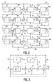
- the processing of an input image I 0 carried out in the workstation 6 is explained in more detail below on the basis of the block diagram according to FIG. 2.
- the input image I 0 is first subjected to low-pass filtering in block 611, the uppermost spatial frequency remaining after the low-pass filtering being half the size of the maximum spatial frequency that can be contained in the input image I 0 .
- subsampling takes place in that the low-pass image in the row and column direction is only calculated for every second pixel.
- the low-pass image I 1 generated in this way is fed, inter alia, to a stage 621 in which, on the one hand, the number of pixels is increased, for example by inserting a row or a column of zeros between every two rows or columns of the low-pass image I 1 and the resulting image is folded with a low-pass kernel.
- the image at the output of stage 621 therefore essentially corresponds to the image which would result if step 611 had not eliminated every second row and column after the low-pass filtering.
- this low-pass image has as many pixels as the input image I 0 from which it is derived.
- this low-pass image - pixel by pixel - is subtracted from the input image I 0 .
- the resulting subtraction image represents the first detail image S 1 , which only contains the higher spatial frequencies of the image I 0 from which it was derived.
- the low-pass image I 1 which represents the lower half of the frequency spectrum of the original image, is processed in the same way as in the previous decomposition level, the input image I 0 .
- the image is thus subjected to low-pass filtering in a stage 612, and at the same time the number of pixels in the row and in the column direction is halved again, so that a low-pass image I 2 results, which is again reduced by a factor of 2, and which is related contains only the lower quarter of the frequency spectrum on the original image.
- the low-pass image I 2 is in turn interpolated in a stage 622 so that a low-pass image with the same number of pixels as the low-pass image I 1 results.
- This low-pass image generated after block 622 is subtracted in block 632 from the image I 1 from which it was derived, so that a second detailed image S 2 results.
- this detail image represents the upper half of the spatial frequency band that adjoins the spatial frequency band contained in the detail image S 1 , but does not include the spatial frequency range contained in the low-pass image I 2 .
- the low-pass image I 2 is processed in the same way as in the second decomposition level, the deep-pass image I 1 .
- the decomposition process can contain n such identically structured decomposition levels. Typical values for n are 7 or 8. This means that the low-pass image I n (which can also be referred to as the residual image) replaces 128 or 256 rows or columns in the input image with a single row or column.
- the input image I 0 could be completely reconstructed from the residual image I n and the detail images S 1 ... S n if the images were added to one another after interpolation had ensured that the images to be added had the same row and column numbers exhibit.
- the interpolation stages 641 ?? 64n contained in the decomposition levels and the addition stages 651, 652, 653 and 65n downstream of them in the individual levels serve this purpose. This reconstruction process is described in detail in the document mentioned at the beginning, to which reference is made to avoid repetition.
- the image value of each pixel in the detail image S i is transformed in a stage 21 with a non-linear transmission characteristic.
- the easiest way to do this is by means of a table memory (look up table), which assigns a possibly changed image value S ei at its output to each image value S i at its input.
- FIG. 4 shows the typical course of the nonlinear characteristic curve (with the image value S i as the abscissa and the image value S ei as the ordinate) according to block 21, but the width of the raised area and the extent of the increase can be different for the different modification levels . It can be seen that large image values remain unchanged, while smaller image values (which may correspond to noise in the first detail image) are raised relative to the larger image values. Since the image values of the detail images represent the contrast of the input image in the respective spatial frequency range, the transmission characteristic indicated increases the weak contrasts in the respective image.
- the image value of each pixel in the detail image S i is then multiplied in a multiplication stage 20 by a factor which is greater than 1. This means that this detail image S i in relation to the remaining image I n (if the modification levels M i + 1 . .... M n does not contain this multiplication but can also be increased in relation to the detail images of the subsequent decomposition levels S i + 1 ... S n ). This multiplication and the associated emphasis on the higher spatial frequencies can, however, possibly also be omitted or already carried out in the reading unit 5.
- the difference ⁇ is then formed in stage 22 between the image value at the output of stage 21 and the image value assigned in the same pixel in the detail image S i .
- This difference ⁇ is multiplied in a multiplier 23 by a factor b which is between 0 and 1.
- the contrast enhancement in block 21 is not effective. However, if b is 1, the contrast enhancement is fully effective.
- the factor b is derived from an image which contains a value corresponding to the average brightness at this point for each pixel in the detail image S i .
- the input image I i + 1 can be used for this, from which the detail image S i is derived because this image contains exactly as many pixels as the detail image.
- This image is subjected to low-pass filtering, the mean image value - ie the density D - being used in a window of, for example, 5 ⁇ 5 pixels, in the center of which is the same pixel, the image value of which is subjected to the weak contrast enhancement in block 21.
- image I n by an additional density correction stage 660 a density correction (for example, corresponding to a film curve) is subjected.
- the filtered image value corresponding to the density D is fed to a table memory LUT i which assigns a value b to each value D.
- the degree to which the contrast enhancement is effective thus depends on the density in a window around the respective pixel and on the course of the characteristic curve stored in the table memory LUT i .
- the following describes how to limit the noise gain, but also how to control the contrast enhancement in an organ-specific manner. The latter works on the assumption that a distinction between organs is possible with the help of the criteria density and detail size. Such an organ-specific control of the contrast enhancement is possible and desirable, particularly in the case of lung images.
- FIG. 6 shows a diagram with the density D as the ordinate and the spatial frequency bands of the individual detail images as the abscissa.
- This diagram shows a region R 1 which is located in the detail images S 1 , S 2 with the highest spatial frequencies and the lowest density.
- the associated density range corresponds to a low radiation dose in an X-ray image. Because of the non-linear, generally logarithmic relationship between the radiation dose and the density, it is known that the noise is most visible in this area.
- FIG. 6 also shows a second area R 2 which corresponds to an average density or an average brightness and which is in a lower spatial frequency range, for example in the detail images S 3 and S 4 .
- a second area R 2 which corresponds to an average density or an average brightness and which is in a lower spatial frequency range, for example in the detail images S 3 and S 4 .
- a large part of the lung vessels are imaged with a lung image with today's usual resolutions of 0.2 mm. If the weak contrasts are increased in this area, a pathological image impression can also result in healthy lungs.
- the structures in the lower density range should be raised in their contrast in the same spatial frequency range. In this area there are, for example, structures that are overlaid by the mediastinum and umbra and are therefore difficult to see. At the same time, noise does not play such a major role in this spatial frequency range.
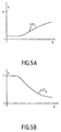
- 5a and 5b show the characteristic curves required for this, which are stored in the table memories LUT i of the modification stages.
- 5a shows the control characteristic for the highest spatial frequency band S 1 (and possibly S 2 ).
- this results in a low value of factor b ie the contrast enhancement brought about by the characteristic according to FIG. 4 is at the output of the stage 24 hardly effective.
- the weak contrasts lying in the range of R 1 - in particular the noise - will therefore not be increased.
- the noise is not reduced, but in practice it is not amplified, as would be the case if all weak contrasts were raised.
- the factor b can increase towards larger density values and thus the extent to which the contrast enhancement takes effect. In this density range, the noise is generally not as disturbing as in the lower density range.
- 5 b shows a characteristic curve as it can be contained in the table memory LUT 3 for the modification in block M 3 . If the density values are low, the factor b is large. This makes the low contrast enhancement at low density in the X-ray image (i.e. in the area of the mediastinum, the shadow of the heart and the abdomen) fully effective. The factor b decreases continuously towards higher values of the density according to FIG. 5b, so that in the sealing area in which the pulmonary vessels are predominantly imaged, the weak contrast enhancement becomes effective to a much lesser extent.
- the characteristic curve according to FIG. 5b is therefore well suited for lung recordings. For others On the other hand, recordings may require a completely different characteristic curve.
- the for various organs optimal curves or image processing parameters should therefore - at least for some of its bases - be stored in the APR database 10 and when the organ to be displayed is specified by the examiner at the subsequent image processing can be specified.
- Fig. 7 shows another embodiment of the modification stage M i .
- the detail image S i is again subjected to a weak contrast enhancement in block 21.
- the resulting detail image with enhanced contrast S ei is combined in a combination stage 27 with the detail image S i pixel by pixel.
- This weighted summation of S e and S ei is equivalent to the combination shown in FIG. 3, the difference ⁇ being formed first between the contrast image S ei and the detail image S i itself and the difference ⁇ then with the weight b is added to the detail image S i .
- the value b is the product of the factors b d and b s , with b d being determined in the same way as the factor b according to FIG. 3.
- the factor b s depends on the variation of the image values in a window around the pixel that is currently being processed according to equation 1. If the image values are weakly varied, the factor b s is small, and if the variation is strong, the factor b s is large. This takes into account the fact that the noise in a pixel in the vicinity of which the image values change greatly is less disturbing than in the case of a pixel in the vicinity of which the image values fluctuate only slightly.
- the variation of the image values can be determined in a variety of ways. For example, three different measures of variation are given here.
- BW (S i ) denotes an image value of S i and ⁇ BW (S i )> the mean value of the image values in a local window around a pixel under consideration.
- C stands for all pixels that are in a local window of size F around the respective pixel.
- P g is the fraction of the pixels with the image value g, and g u and g o represent the minimum and maximum gray value, respectively.
- a Wen b s is assigned to the respectively determined value T with a table memory 29 which is large for large T and small for small values of T.
- the values for b d and b s are then multiplied together in block 30, which gives the factor b for the respective pixel.
- the main difference compared to FIG. 3 is that the value b s is also included in the factor b.
- Blocks 25 and 26 could then be omitted.
- the insensitivity to noise would then also be other medical images (e.g. magnetic resonance images), independently whether the noise is more visible in bright parts of the image than in dark ones.
Abstract
Description
- Zerlegung des Eingangsbildes in eine Folge von Detailbildern, die jeweils nur einen Teil der Ortsfrequenzen des Eingangsbildes enthalten.
- Modifikation mindestens eines Teils der zu den Pixeln wenigstens eines der Detailbilder gehörenden Bildwerte,
- Rekonstruktion eines Ausgangsbildes aus den ggf. gefilterten Detailbildern.
- Fig. 1
- ein Röntgenaufnahmegerät mit einer erfindungsgemäßen Bildverarbeitungsvorrichtung,
- Fig. 2
- ein Blockdiagramm zur Erläuterung der Bildverarbeitung,
- Fig. 3
- ein Blockdiagramm der darin enthaltenen Modifikationsstufe,
- Fig. 4
- eine Kennlinie zur Anhebung der schwachen Kontraste,
- Fig. 5 a 5b
- verschiedene Kennlinien zur Steuerung der Schwachkontrastanhebung,
- Fig. 6
- ein Dichte/Ortsfrequenzdiagramm und
- Fig. 7
- eine weitere Ausgestaltung der Modifikationsstufe.
Claims (6)
- Verfahren zur Verarbeitung eines Eingangsbildes mit folgenden Schritten:Zerlegung des Eingangsbitdes in eine Folge von Detailbildern, die jeweils nur einen Teil der Ortsfrequenzen des Eingangsbildes enthalten,Modifikation mindestens eines Teils der zu den Pixeln wenigstens eines der Detailbilder gehörenden Bildwerte,Rekonstruktion eines Ausgangsbildes aus den ggf. gefilterten Derailbildern,
dadurch gekennzeichnet, daß die Modifikation eines Bildwertes der Multiplikation dieses Bildwertes mit einem Faktor entspricht, der sowohl von diesem Bildwert selbst als auch von dem mittleren Bildwert und/oder der Variation der Bildwerte in einem Fenster um das jeweilige Pixel in dem Eingangsbild oder einem daraus abgeleiteten Bild abhängt. - Verfahren nach Anspruch 1
dadurch gekennzeichnet, daß die Modifikation folgende Schritte umfaßt:Konvertierung der Bildwerte in wenigstens einem der Detailbilder mit einer nichtlinearen Kennlinie derart, daß die niedrigen Bildwerte in dem Detailbild im Vergleich zu den größeren angehoben werden,Steuerung des Ausmaßes der Anhebung der niedrigen Bildwerte in den Pixeln des Detailbildes in Abhängigkeit von dem mittleren Bildwert und/oder der Variation der Bildwerte in einem Fenster um die jeweiligen Pixel in dem Eingangsbild oder einem daraus abgeleiteten Bild. - Verfahren nach Anspruch 2,
dadurch gekennzeichnet, daß die Steuerung des Ausmaßes der Anhebung des Bildwertes eines jeden Pixels die gewichtete Summierung der Bildwertes in dem Detailbild und in dem konvertierten Detailbild mit einem Anteilsfaktor umfaßt, der von dem mittleren Bildwert und/oder der Variation der Bildwerte in einem Fenster um das jeweilige Pixel in dem Eingangsbild oder einem daraus abgeleiteten Bild abhängt. - Verfahren nach Anspruch 3, insbesondere für eine Röntgenaufnahme als Eingangsbild, dadurch gekennzeichnet, daß zumindest für die Detailbilder mit den höchsten Ortsfrequenzen die Anteilsfaktoren solche Werte haben, daß das Ausmaß der Anhebung Anhebungen mit abnehmender Dichte und/oder abnehmender Variation reduziert wird.
- Vorrichtung zur Durchführung des Verfahrens nach Anspruch 1 mit einem Bildgebungssystem (1, 4, 5) und einer Bildverabeitungseinheit (10), die versehen ist mitMitteln (611, 621, 631......61n, 62n, 63n) zur Zerlegung des Eingangsbildes (I0) in eine Folge von Detailbildern (S1, S2..... Sn), die jeweils nur einen Teil der Ortsfrequenzen des Eingangsbildes (I0) enthalten,Mitteln zur Modifikation (M1, M2..... Mn) mindestens eines Teils der zu den Pixeln wenigstens eines der Detailbilder gehörenden Bildwerte,Mitteln (641, 651......64n, 65n) zur Rekonstruktion eines Ausgangsbildes (Im) aus den ggf. modifiziertenen Detailbildern (Sm1, Sm2..... Smn)
dadurch gekennzeichnet, daß die Mitteln zur Modifikation (M1, M2..... Mn) so ausgebildet sind, daß die Modifikation eines Bildwertes der Multiplikation dieses Bildwertes mit einem Faktor entspricht, der sowohl von diesem Bildwert selbst als auch von dem mittleren Bildwert und/oder der Variation der Bildwerte in einem Fenster um das jeweilige Pixel in dem Eingangsbild oder einem daraus abgeleiteten Bild abhängt. - Vorrichtung nach Anspruch 5,
dadurch gekennzeichnet, daß die Vorrichtung als Bildgebungssystem einen Röntgenstrahler (1) und einen Röntgen-Bildaufnehmer (4) zwecks Darstellung unterschiedlicher Organe durch Röntgenaufnahmen enthält, daß der Röntgenstrahler von einem Röntgengeneraror (7) gesteuert wird und daß eine Speicheranordnung (10) vorgesehen ist, in der für eine Anzahl von Organen je ein Satz von Aufnahmeparametern gespeichert ist, daß jeder Satz neben Aufnahmeparametern für den Röntgengenerator Parameter für die Modifikation der Detailbilder in Abhängikeit von dem mittleren Bildwert und/oder der Variation der Bildwerte in einem Fenster um das jeweilige Pixel in der Eingangsbild oder einem daraus abgeleiteten Bild enthält, und daß bei einer Vorgabe eines Organs die für dieses Organ gespeicherte die Modifikation der Detailbilder aufgerufen und der Bildverabeitungseinheit vorgegeben wird.
Applications Claiming Priority (2)
| Application Number | Priority Date | Filing Date | Title |
|---|---|---|---|
| DE19849090A DE19849090A1 (de) | 1998-10-24 | 1998-10-24 | Verfahren zur Verarbeitung eines Eingangsbildes |
| DE19849090 | 1998-10-24 |
Publications (2)
| Publication Number | Publication Date |
|---|---|
| EP0996090A2 true EP0996090A2 (de) | 2000-04-26 |
| EP0996090A3 EP0996090A3 (de) | 2000-12-06 |
Family
ID=7885526
Family Applications (1)
| Application Number | Title | Priority Date | Filing Date |
|---|---|---|---|
| EP99203395A Withdrawn EP0996090A3 (de) | 1998-10-24 | 1999-10-15 | Verfahren zur Verarbeitung eines Eingangsbildes |
Country Status (4)
| Country | Link |
|---|---|
| US (1) | US6252931B1 (de) |
| EP (1) | EP0996090A3 (de) |
| JP (1) | JP2000132674A (de) |
| DE (1) | DE19849090A1 (de) |
Cited By (4)
| Publication number | Priority date | Publication date | Assignee | Title |
|---|---|---|---|---|
| EP1271405A2 (de) * | 2001-06-19 | 2003-01-02 | Canon Kabushiki Kaisha | Bildverbesserung unter Verwendung einer Frequenzbandzerlegung |
| EP1339018A1 (de) * | 2000-11-30 | 2003-08-27 | Canon Kabushiki Kaisha | Bildverarbeitungseinrichtung, bildverarbeitungsverfahren, aufzeichnungsmedium und programm |
| EP1341123A1 (de) * | 2000-11-30 | 2003-09-03 | Canon Kabushiki Kaisha | Bildverarbeitungseinrichtung, bildverarbeitungsverfahren, aufzeichnungsmedium und programm |
| WO2013076662A1 (en) * | 2011-11-25 | 2013-05-30 | Koninklijke Philips Electronics N.V. | Spectral image processing in x-ray imaging |
Families Citing this family (29)
| Publication number | Priority date | Publication date | Assignee | Title |
|---|---|---|---|---|
| US6778692B1 (en) * | 2000-08-11 | 2004-08-17 | General Electric Company | Image processing method and apparatus including image improving circuit |
| DE10139708A1 (de) * | 2001-08-11 | 2003-02-20 | Philips Corp Intellectual Pty | Vorrichtung und Verfahren zur Verarbeitung von Digitalbildern |
| JP3951695B2 (ja) | 2001-12-11 | 2007-08-01 | ソニー株式会社 | 画像配信システムおよび方法、画像配信装置および方法、画像受信装置および方法、記録媒体、並びにプログラム |
| US7102792B2 (en) * | 2002-01-16 | 2006-09-05 | Xerox Corporation | Systems and methods for modifying image data for background printing |
| DE10306555A1 (de) * | 2002-03-06 | 2003-09-18 | Siemens Ag | Verfahren zur Bearbeitung einer mit einem dynamischen Bildwandler, insbesondere einem Festkörperbilddetektor aufgenommenen Strahlungsbildsequenz bestehend aus mehreren nacheinander aufgenommenen Strahlungsbildern eines Untersuchungsobjekts |
| US7149335B2 (en) * | 2002-09-27 | 2006-12-12 | General Electric Company | Method and apparatus for enhancing an image |
| DE10250197A1 (de) * | 2002-10-28 | 2004-05-13 | Siemens Ag | Bildsystem zur Verarbeitung von Bilddaten |
| US6944265B2 (en) * | 2002-11-25 | 2005-09-13 | Ge Medical Systems Global Technology Company, Llc | Image pasting using geometry measurement and a flat-panel detector |
| DE10324908B4 (de) * | 2003-05-30 | 2007-03-22 | Siemens Ag | Selbstlernendes Verfahren zur Bildaufbereitung von digitalen Röntgenbildern sowie zugehörige Vorrichtung |
| US6895076B2 (en) | 2003-06-03 | 2005-05-17 | Ge Medical Systems Global Technology Company, Llc | Methods and apparatus for multiple image acquisition on a digital detector |
| CN1860500A (zh) * | 2003-09-22 | 2006-11-08 | 皇家飞利浦电子股份有限公司 | 利用时间滤波器来增强医学图像 |
| JP4069943B2 (ja) * | 2003-12-03 | 2008-04-02 | 株式会社ニコン | ノイズ除去の強弱を画面内でコントロールする画像処理装置、画像処理プログラム、画像処理方法、および電子カメラ |
| WO2006079997A2 (en) * | 2005-01-31 | 2006-08-03 | Koninklijke Philips Electronics N.V. | Pyramidal decomposition for multi-resolution image filtering |
| WO2006120585A2 (en) * | 2005-03-03 | 2006-11-16 | Koninklijke Philips Electronics N.V. | Image enhancement |
| DE102005032287B4 (de) * | 2005-07-11 | 2010-11-11 | Siemens Ag | Bearbeitungsverfahren für ein zweidimensionales Anfangsbild und hiermit korrespondierende Gegenstände |
| US7689017B2 (en) * | 2005-12-28 | 2010-03-30 | The General Hospital Corporation | Medical image processing |
| DE102006029718A1 (de) * | 2006-06-28 | 2008-01-10 | Siemens Ag | Verfahren zur Auswertung zweier Abbilder sowie medizinisches Abbildungssystem |
| JP4752719B2 (ja) * | 2006-10-19 | 2011-08-17 | ソニー株式会社 | 画像処理装置、画像取得方法及びプログラム |
| WO2008141293A2 (en) * | 2007-05-11 | 2008-11-20 | The Board Of Regents Of The University Of Oklahoma One Partner's Place | Image segmentation system and method |
| US8731318B2 (en) * | 2007-07-31 | 2014-05-20 | Hewlett-Packard Development Company, L.P. | Unified spatial image processing |
| US20090034870A1 (en) * | 2007-07-31 | 2009-02-05 | Renato Keshet | Unified spatial image processing |
| EP2026278A1 (de) * | 2007-08-06 | 2009-02-18 | Agfa HealthCare NV | Verfahren zur Erhöhung des Kontrasts in einem Bild |
| JP5538684B2 (ja) * | 2008-03-13 | 2014-07-02 | キヤノン株式会社 | 画像処理装置、画像処理方法、プログラム、及び記憶媒体 |
| JP6408472B2 (ja) | 2012-10-05 | 2018-10-17 | コーニンクレッカ フィリップス エヌ ヴェKoninklijke Philips N.V. | サブ画像ビューを最適化するリアルタイム画像処理 |
| US10282823B2 (en) | 2014-11-24 | 2019-05-07 | Koninklijke Philips N.V. | Simulating dose increase by noise model based multi scale noise reduction |
| US11164295B2 (en) * | 2015-09-17 | 2021-11-02 | Michael Edwin Stewart | Methods and apparatus for enhancing optical images and parametric databases |
| US10839487B2 (en) * | 2015-09-17 | 2020-11-17 | Michael Edwin Stewart | Methods and apparatus for enhancing optical images and parametric databases |
| CN108369732B (zh) | 2015-11-26 | 2022-08-23 | 皇家飞利浦有限公司 | 具有用于增强医学图像的用户接口的装置 |
| US11049226B1 (en) * | 2019-04-23 | 2021-06-29 | Bae Systems Information And Electronics Systems Integration Inc. | Median based frequency separation local area contrast enhancement |
Citations (3)
| Publication number | Priority date | Publication date | Assignee | Title |
|---|---|---|---|---|
| EP0505200A2 (de) * | 1991-03-20 | 1992-09-23 | Fujitsu Limited | Verfahren zum Verarbeiten von Strahlungsbildern mit selektiver Erhöhung geringer Bilddichteänderungen |
| EP0527525A2 (de) * | 1991-08-14 | 1993-02-17 | Agfa-Gevaert N.V. | Verfahren und Vorrichtung zur Kontrastverbesserung von Bildern |
| US5644662A (en) * | 1993-02-11 | 1997-07-01 | Agfa-Gevaert | Multiple processing of radiographic images based on a pyramidal image decomposition |
Family Cites Families (7)
| Publication number | Priority date | Publication date | Assignee | Title |
|---|---|---|---|---|
| JPH06114046A (ja) * | 1992-09-30 | 1994-04-26 | Shimadzu Corp | X線テレビジョン装置 |
| JPH06139287A (ja) * | 1992-10-30 | 1994-05-20 | Toshiba Corp | 画像記録再生装置 |
| US5485500A (en) * | 1993-01-29 | 1996-01-16 | Hitachi Medical Corporation | Digital x-ray imaging system and method |
| EP0610603B1 (de) * | 1993-02-11 | 1999-09-08 | Agfa-Gevaert N.V. | Verfahren zur schnellen interaktiven Offline-Verarbeitung von Röntgenbildern |
| JP3435192B2 (ja) * | 1993-09-02 | 2003-08-11 | 株式会社東芝 | X線診断装置 |
| EP0712092A1 (de) * | 1994-11-10 | 1996-05-15 | Agfa-Gevaert N.V. | Verfahren zur Bildverbesserung |
| US5787146A (en) * | 1996-10-18 | 1998-07-28 | Spad Technologies, Inc. | X-ray imaging system using diffractive x-ray optics for high definition low dosage three dimensional imaging of soft tissue |
-
1998
- 1998-10-24 DE DE19849090A patent/DE19849090A1/de not_active Withdrawn
-
1999
- 1999-10-15 EP EP99203395A patent/EP0996090A3/de not_active Withdrawn
- 1999-10-21 JP JP11299797A patent/JP2000132674A/ja not_active Withdrawn
- 1999-10-22 US US09/425,653 patent/US6252931B1/en not_active Expired - Fee Related
Patent Citations (3)
| Publication number | Priority date | Publication date | Assignee | Title |
|---|---|---|---|---|
| EP0505200A2 (de) * | 1991-03-20 | 1992-09-23 | Fujitsu Limited | Verfahren zum Verarbeiten von Strahlungsbildern mit selektiver Erhöhung geringer Bilddichteänderungen |
| EP0527525A2 (de) * | 1991-08-14 | 1993-02-17 | Agfa-Gevaert N.V. | Verfahren und Vorrichtung zur Kontrastverbesserung von Bildern |
| US5644662A (en) * | 1993-02-11 | 1997-07-01 | Agfa-Gevaert | Multiple processing of radiographic images based on a pyramidal image decomposition |
Non-Patent Citations (2)
| Title |
|---|
| POLESEL A ET AL: "ADAPTIVE UNSHARP MASKING FOR CONTRAST ENHANCEMENT" PROCEEDINGS OF THE INTERNATIONAL CONFERENCE ON IMAGE PROCESSING,US,LOS ALAMITOS, CA: IEEE, 26. Oktober 1997 (1997-10-26), Seiten 267-270, XP000792764 ISBN: 0-8186-8184-5 * |
| RAMPONI G ET AL: "NONLINEAR UNSHARP MASKING METHODS FOR IMAGE CONTRAST ENHANCEMENT" JOURNAL OF ELECTRONIC IMAGING,US,SPIE + IS&T, Bd. 5, Nr. 3, Juli 1996 (1996-07), Seiten 353-366, XP000885316 ISSN: 1017-9909 * |
Cited By (15)
| Publication number | Priority date | Publication date | Assignee | Title |
|---|---|---|---|---|
| EP1341123A4 (de) * | 2000-11-30 | 2007-07-25 | Canon Kk | Bildverarbeitungseinrichtung, bildverarbeitungsverfahren, aufzeichnungsmedium und programm |
| EP1816603A1 (de) * | 2000-11-30 | 2007-08-08 | Canon Kabushiki Kaisha | Bildverarbeitungsvorrichtung, Bildverarbeitungsverfahren, Speichermedium und Programm |
| EP1341123A1 (de) * | 2000-11-30 | 2003-09-03 | Canon Kabushiki Kaisha | Bildverarbeitungseinrichtung, bildverarbeitungsverfahren, aufzeichnungsmedium und programm |
| US7561750B2 (en) | 2000-11-30 | 2009-07-14 | Canon Kabushiki Kaisha | Image processing apparatus, image processing method, storage medium, and program |
| US7558434B2 (en) | 2000-11-30 | 2009-07-07 | Canon Kabushiki Kaisha | Image processing apparatus, image processing method, storage medium, and program |
| EP1339018A4 (de) * | 2000-11-30 | 2005-11-16 | Canon Kk | Bildverarbeitungseinrichtung, bildverarbeitungsverfahren, aufzeichnungsmedium und programm |
| EP1339018A1 (de) * | 2000-11-30 | 2003-08-27 | Canon Kabushiki Kaisha | Bildverarbeitungseinrichtung, bildverarbeitungsverfahren, aufzeichnungsmedium und programm |
| US7248748B2 (en) | 2000-11-30 | 2007-07-24 | Canon Kabushiki Kaisha | Image processing apparatus, image processing method, storage medium, and program |
| US7076111B2 (en) | 2000-11-30 | 2006-07-11 | Canon Kabushiki Kaisha | Image processing apparatus, image processing method, storage medium, and program |
| US7447376B2 (en) | 2000-11-30 | 2008-11-04 | Canon Kabushiki Kaisha | Image processing apparatus, image processing method, storage medium, and program |
| US7079700B2 (en) | 2000-11-30 | 2006-07-18 | Canon Kabushiki Kaisha | Image processing apparatus, image processing method, storage medium, and program |
| EP1271405A2 (de) * | 2001-06-19 | 2003-01-02 | Canon Kabushiki Kaisha | Bildverbesserung unter Verwendung einer Frequenzbandzerlegung |
| US6813335B2 (en) | 2001-06-19 | 2004-11-02 | Canon Kabushiki Kaisha | Image processing apparatus, image processing system, image processing method, program, and storage medium |
| EP1271405A3 (de) * | 2001-06-19 | 2003-12-03 | Canon Kabushiki Kaisha | Bildverbesserung unter Verwendung einer Frequenzbandzerlegung |
| WO2013076662A1 (en) * | 2011-11-25 | 2013-05-30 | Koninklijke Philips Electronics N.V. | Spectral image processing in x-ray imaging |
Also Published As
| Publication number | Publication date |
|---|---|
| US6252931B1 (en) | 2001-06-26 |
| JP2000132674A (ja) | 2000-05-12 |
| EP0996090A3 (de) | 2000-12-06 |
| DE19849090A1 (de) | 2000-04-27 |
Similar Documents
| Publication | Publication Date | Title |
|---|---|---|
| EP0996090A2 (de) | Verfahren zur Verarbeitung eines Eingangsbildes | |
| DE2952422C3 (de) | Verfahren und Vorrichtung zum Verarbeiten eines Röntgenbildes bei einem Röntgenbild-Kopiersystem | |
| EP0482712B1 (de) | Verfahren zur Dynamikkompression in Röntgenaufnahmen und Vorrichtung zur Durchführung des Verfahrens | |
| DE69629445T2 (de) | Automatische Tonskalenabstimmung mittels Bildaktivitätsmessungen | |
| EP0681269B1 (de) | Verfahren zur Wiedergabe insbesondere einer digitalen Röntgenaufnahme als sichtbares Bild sowie Anordnung zur Durchführung des Verfahrens | |
| DE3738636C2 (de) | ||
| EP0938063B1 (de) | Verfahren zur zweidimensionalen Abbildung von Strukturen für die medizinische Diagnostik | |
| DE3216458A1 (de) | Einrichtung und verfahren zur erzeugung eines kontrastmittel-projektionsbildes | |
| DE3426933A1 (de) | Anordnung zum selbsttaetigen korrigieren von fehluebertragungen | |
| EP1302899A2 (de) | Vorrichtung und Verfahren zur Verarbeitung von Digitalbildern | |
| DE102006005803A1 (de) | Verfahren zur Rauschreduktion in bildgebenden Verfahren | |
| DE3704685A1 (de) | Anordnung und verfahren zur korrektur bzw. kompensation von streustrahlung durch adaptive filterung | |
| DE102007046941B4 (de) | Verfahren zur Darstellung von medizinischen Bildern sowie Röntgendiagnostikeinrichtung | |
| EP1111909A1 (de) | Vorrichtung und Verfahren zur Darstellung eines aus mehreren Teilbereichen zusammengesetzten Bildes | |
| DE102005010076A1 (de) | Bildbearbeitungsverfahren für ein digitales medizinisches Untersuchungsbild und zugehörige Untersuchungseinrichtung | |
| DE102005047539A1 (de) | Bildverarbeitungsverfahren zur Fensterung und/oder Dosisregelung für medizinische Diagnostikeinrichtungen | |
| DE60202588T2 (de) | Verfahren zur Rauschminderung | |
| DE3725826C2 (de) | ||
| DE2952423C2 (de) | ||
| DE60214967T2 (de) | Verfahren zur Kontrastverbesserung eines Bildes | |
| DE102005003226B4 (de) | Verfahren und Einrichtung zur Wiedergabe eines Röntgenbildes | |
| DE3141041A1 (de) | "verfahren zur herstellung von roentgenbildern und roentgenfernsehgeraet zu seiner duchfuehrung" | |
| DE2952426C2 (de) | Verfahren und Vorrichtung zum Verarbeiten eines Strahlungsbildes | |
| EP0444737A2 (de) | Anordnung zum Abtasten einer Röntgenaufnahme | |
| EP1080450B1 (de) | Verfahren zur rausch- und artefaktreduktion bei digitalen subtraktionsbildverfahren |
Legal Events
| Date | Code | Title | Description |
|---|---|---|---|
| PUAI | Public reference made under article 153(3) epc to a published international application that has entered the european phase |
Free format text: ORIGINAL CODE: 0009012 |
|
| AK | Designated contracting states |
Kind code of ref document: A2 Designated state(s): DE FR GB NL |
|
| AX | Request for extension of the european patent |
Free format text: AL;LT;LV;MK;RO;SI |
|
| PUAL | Search report despatched |
Free format text: ORIGINAL CODE: 0009013 |
|
| AK | Designated contracting states |
Kind code of ref document: A3 Designated state(s): AT BE CH CY DE DK ES FI FR GB GR IE IT LI LU MC NL PT SE |
|
| AX | Request for extension of the european patent |
Free format text: AL;LT;LV;MK;RO;SI |
|
| RIC1 | Information provided on ipc code assigned before grant |
Free format text: 7G 06T 5/20 A, 7G 06T 5/00 B |
|
| 17P | Request for examination filed |
Effective date: 20010606 |
|
| AKX | Designation fees paid |
Free format text: DE FR GB NL |
|
| RAP1 | Party data changed (applicant data changed or rights of an application transferred) |
Owner name: KONINKLIJKE PHILIPS ELECTRONICS N.V. Owner name: PHILIPS CORPORATE INTELLECTUAL PROPERTY GMBH |
|
| RAP1 | Party data changed (applicant data changed or rights of an application transferred) |
Owner name: KONINKLIJKE PHILIPS ELECTRONICS N.V. Owner name: PHILIPS INTELLECTUAL PROPERTY & STANDARDS GMBH |
|
| STAA | Information on the status of an ep patent application or granted ep patent |
Free format text: STATUS: THE APPLICATION HAS BEEN WITHDRAWN |
|
| 18W | Application withdrawn |
Effective date: 20071121 |