BACKGROUND OF THE INVENTION
Field of the Invention
This invention relates to an apparatus for recording and
reproducing information. This invention also relates to a method of
recording and reproducing information.
Description of the Related Art
A known digital recording and reproducing apparatus
compressively encodes an input video signal into a first digital video
signal of a given code. Every segment of the first digital video signal
which corresponds to a predetermined number M of frames (a
plurality of frames) is processed as follows. Words of a given error
correction code are generated in response to every M-frame-corresponding
segment of the first digital video signal. The error
correction code words and the M-frame-corresponding segment of
the first digital video signal are combined into an M-frame-corresponding
segment of a second digital video signal. The second
digital video signal is subjected to modulation for record. The
modulation-resultant video signal is recorded on a magnetic tape.
The known digital recording and reproducing apparatus
reproduces a video signal from a magnetic tape. The reproduced
video signal is subjected to demodulation. Every M-frame-corresponding
segment of the demodulation-resultant digital video
signal is separated into error correction code words and an M-frame-corresponding
segment of a third digital video signal. The M-frame-corresponding
segment of the third digital video signal is
corrected into an M-frame-corresponding segment of a fourth
digital video signal in response to the error correction code words.
The fourth digital video signal is decoded into an original video
signal. The known digital recording and reproducing apparatus
outputs the decoding-resultant video signal, that is, the reproduced
original video signal.
A first video signal which has been recorded on a magnetic
tape can be edited by the known digital recording and reproducing
apparatus. For example, a second video signal is recorded over a
portion of the first video signal which follows an editing point. In
this case, only the portion of the first video signal which precedes
the editing point remains on the magnetic tape. In the known
digital recording and reproducing apparatus, the first video signal
results from the processing of video information M frames by M
frames. Accordingly, it is desirable that the editing point coincides
with the boundary between M-frame-corresponding segments of the
first video signal. In this case, during playback implemented after
the editing process, all the video information represented by the
remaining portion of the first video signal on the magnetic tape can
be reproduced. On the other hand, in the case where the editing
point is in an intermediate part of an M-frame-corresponding
segment of the first video signal, after the editing process, the video
information represented by a remaining part of the M-frame-corresponding
segment of the first video signal will fail to be
reproduced during playback. Thus, in the known digital recording
and reproducing apparatus, the minimum unit of movement of the
editing point corresponds to M frames.
SUMMARY OF THE INVENTION
It is a first object of this invention to provide an apparatus for
recording and reproducing information which can implement an
editing process having a smaller unit of movement of an editing
point.
It is a second object of this invention to provide a method of
recording and reproducing information which can implement an
editing process having a smaller unit of movement of an editing
point.
A first aspect of this invention provides an information
recording and reproducing apparatus comprising a memory for
storing a signal whose amount corresponds to a minimum recording
unit; first means for reproducing first data from a minimum-recording-unit
corresponding portion of a recording medium, the
minimum-recording-unit corresponding portion containing a
designated editing point; second means for storing the first data
reproduced by the first means into the memory; third means for
detecting a boundary between frames represented by the first data
in the memory which has been stored thereinto by the second
means, the detected boundary corresponding to the editing point;
fourth means for storing an address of a storage segment in the
memory which corresponds to the boundary detected by the third
means; fifth means for replacing a first portion of the first data in
the memory which corresponds to the address stored by the fourth
means and later addresses by second data while leaving a second
portion of the first data in the memory which corresponds to
addresses preceding the address stored by the fourth means to
generate third data composed of the second data and the second
portion of the first data in the memory; and sixth means for
recording the third data on the minimum-recording-unit
corresponding portion of the recording medium.
A second aspect of this invention is based on the first aspect
thereof, and provides an information recording and reproducing
apparatus wherein information recorded on the recording medium
is divided into pieces each corresponding to the minimum
recording unit, and each of the pieces of the information has a fixed
amount of data.
A third aspect of this invention provides a method of
recording and reproducing information which uses a memory for
storing a signal whose amount corresponds to a minimum recording
unit. The method comprises the steps of reproducing first data
from a minimum-recording-unit corresponding portion of a
recording medium, the minimum-recording-unit corresponding
portion containing a designated editing point; storing the
reproduced first data into the memory; detecting a boundary
between frames represented by the first data in the memory, the
detected boundary corresponding to the editing point; storing an
address of a storage segment in the memory which corresponds to
the detected boundary; replacing a first portion of the first data in
the memory which corresponds to the stored address and later
addresses by second data while leaving a second portion of the first
data in the memory which corresponds to addresses preceding the
stored address to generate third data composed of the second data
and the second portion of the first data in the memory; and
recording the third data on the minimum-recording-unit
corresponding portion of the recording medium.
A fourth aspect of this invention is based on the third aspect
thereof, and provides a method wherein information recorded on
the recording medium is divided into pieces each corresponding to
the minimum recording unit, and each of the pieces of the
information has a fixed amount of data.
BRIEF DESCRIPTION OF THE DRAWINGS
Fig. 1 is a block diagram of an information recording and
reproducing apparatus according to a first embodiment of this
invention.
Fig. 2 is a diagram of a sequence of N-frame intervals in a
magnetic tape in Fig. 1.
Fig. 3 is a diagram of a first signal storing condition of a
memory in Fig. 1.
Fig. 4 is a diagram of a second signal storing condition of the
memory in Fig. 1.
Fig. 5 is a diagram of a sequence of N-frame intervals in the
magnetic tape in Fig. 1.
Fig. 6 is a time-domain diagram of signals in a second
embodiment of this invention.
DESCRIPTION OF THE PREFERRED EMBODIMENTS
First Embodiment
Fig. 1 shows an information recording and reproducing
apparatus according to a first embodiment of this invention. The
apparatus of Fig. 1 includes a video processing circuit 11, a frame
change point detection circuit 12, a memory 13, an error
correction code (ECC) circuit 14, a modulation circuit 15A, a
demodulation circuit 15B, and a magnetic head 16. For example,
the magnetic head 16 has a plurality of sub magnetic heads.
The video processing circuit 11 is connected to the memory
13. The frame change point detection circuit 12 is connected to
the video processing circuit 11 and the memory 13. The memory
13 is connected to the modulation circuit 15A and the
demodulation circuit 15B. The ECC circuit 14 is connected to the
memory 13. The modulation circuit 15A and the demodulation
circuit 15B are connected to the magnetic head 16. The magnetic
head 16 is mounted on a rotary drum. A magnetic tape 17 is
wrapped around the rotary drum in a predetermined angular range.
The magnetic tape 17 can be fed relative to the rotary drum while
being scanned by the magnetic head 16.
Operation of the apparatus in Fig. 1 can be changed among
different modes including a recording mode, a playback mode, and
an editing mode.
During the recording mode of operation, the video processing
circuit 11 receives an input video signal. The video processing
circuit 11 includes an encoder. The video processing circuit 11
encodes the input video signal into a first digital video signal of a
given code. The video processing circuit 11 may compressively
encode the input video signal into a digital video signal of a
predetermined code which conforms with a type of the MPEG
(Moving Picture Experts Group) standards. The video processing
circuit 11 feeds the first digital video signal to the memory 13. The
first digital video signal is divided into successive segments each
corresponding to a predetermined number N of frames, where the
predetermined number N is equal to a predetermined natural
number. For example, the predetermined number N is equal to or
greater than two. The first digital video signal is processed N
frames by N frames as follows. Every N-frame-corresponding
segment of the first digital video signal is temporarily stored in the
memory 13. The ECC circuit 14 accesses the N-frame-corresponding
segment of the first digital video signal in the
memory 13, and generates words of a given error correction code in
response to the accessed N-frame-corresponding segment of the
first digital video signal. The ECC circuit 14 combines the error
correction code words and the N-frame-corresponding segment of
the first digital video signal into an N-frame-corresponding segment
of a second digital video signal. The ECC circuit 14 writes the N-frame-corresponding
segment of the second digital video signal into
the memory 13.
During the recording mode of operation, the second digital
video signal is read out from the memory 13 before being fed to the
modulation circuit 15A. The modulation circuit 15A subjects the
second digital video signal to modulation for record. The
modulation-resultant video signal is transmitted from the
modulation circuit 15A to the magnetic head 16 mounted on the
rotary drum. The magnetic head 16 records the modulation-resultant
video signal on the magnetic tape 17 while the magnetic
tape 17 is fed relative to the rotary drum.
During the playback mode of operation, the magnetic head 16
reproduces a video signal from the magnetic tape 17 while the
magnetic tape 17 is fed relative to the rotary drum. The
reproduced video signal is transmitted from the magnetic head 16
to the demodulation circuit 15B. The demodulation circuit 15B
subjects the reproduced video signal to demodulation which is
inverse with respect to the modulation implemented by the
modulation circuit 15A. Thus, the demodulation circuit 15B
demodulates the reproduced video signal into a third digital video
signal (a demodulation-resultant digital video signal). The
demodulation circuit 15B feeds the third digital video signal to the
memory 13. The third digital video signal is divided into successive
segments each corresponding to N frames. The third digital video
signal is processed N frames by N frames as follows. Every N-frame-corresponding
segment of the third digital video signal is
temporarily stored in the memory 13. The ECC circuit 14 accesses
the N-frame-corresponding segment of the third digital video signal
in the memory 13, and separates the N-frame-corresponding
segment of the third digital video signal into error correction code
words and an N-frame-corresponding segment of a fourth digital
video signal. The ECC circuit 14 corrects the N-frame-corresponding
segment of the fourth digital video signal into an N-frame-corresponding
segment of a fifth digital video signal in
response to the error correction code words. The ECC circuit 14
writes the N-frame-corresponding segment of the fifth digital video
signal into the memory 13.
During the playback mode of operation, the fifth digital video
signal is read out from the memory 13 before being fed to the video
processing circuit 11. The video processing circuit 11 includes a
decoder. The video processing circuit 11 decodes the fifth digital
video signal into an original video signal. The decoding by the video
processing circuit 11 is inverse with respect to the encoding
implemented thereby during the recording mode of operation. The
video processing circuit 11 outputs the decoding-resultant video
signal, that is, the reproduced original video signal.
The editing mode of operation of the apparatus in Fig. 1 is as
follows. It is assumed that the number N is equal to or greater than
four, and hence N frames are four frames or more. Frames
represented by a video signal on the magnetic tape 17 are separated
into groups each having N successive frames. Each of these frame
groups corresponds to a minimum recording unit.
As shown in Fig. 2, the magnetic tape 17 has a sequence of N-frame
intervals ···, (A), (B), (C), (D), (E), (F), ··· to which frame
groups are assigned respectively. It is assumed that a designated
editing point 21 exists in an intermediate part of the N-frame
interval (C), and coincides with the boundary between a third frame
and a fourth frame in the group assigned to the N-frame interval (C).
The apparatus in Fig. 1 includes an operation unit (not shown) via
which a user can designate an editing point. A signal of the
designated editing point is generated by actuating the operation
unit.
During a first stage of the editing mode of operation, the
magnetic tape 17 is controlled in response to the signal of the
designated editing point 21 so that The N-frame interval (C) which
contains the designated editing point 21 will be accessed by the
magnetic head 16, and playback will be implemented. Specifically,
a video signal (an old modulation-resultant video signal) is
reproduced from the whole of the N-frame interval (C) by the
magnetic head 16. The reproduced video signal is transmitted from
the magnetic head 16 to the demodulation circuit 15B. The
demodulation circuit 15B demodulates the reproduced video signal
into a demodulation-resultant digital video signal. The
demodulation circuit 15B feeds the demodulation-resultant digital
video signal to the memory 13. The demodulation-resultant digital
video signal is written into the memory 13. During the writing of
The demodulation-resultant digital video signal into the memory 13,
an address signal used in the memory 13 is updated in a normal
order. The demodulation-resultant digital video signal which
represents N frames in the group assigned to the N-frame interval
(C) is thus stored in the memory 13. The ECC circuit 14 accesses
the demodulation-resultant digital video signal in the memory 13,
and separates the demodulation-resultant digital video signal into
error correction code words and an N-frame-corresponding digital
video signal. The ECC circuit 14 corrects the N-frame-corresponding
digital video signal into a correction-resultant digital
video signal in response to the error correction code words. The
ECC circuit 14 writes the correction-resultant digital video signal
into the memory 13. During the writing of the correction-resultant
digital video signal into the memory 13, the address signal used in
the memory 13 is updated in the normal order. Then, further
writing of data into the memory 13 is suspended. The correction-resultant
digital video signal stored in the memory 13 represents N
frames in the group assigned to the N-frame interval (C).
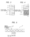
Specifically, as shown in Fig. 3, a set of the N frames represented by
the correction-resultant digital video signal in the memory 13 is a
sequence of a first frame C-0, a second frame C-1, a third frame
C-2, a fourth frame C-3, ···, and an N-th frame C-N-1. The
designated editing point 21 (see Fig. 2) coincides with the boundary
between the third frame C-2 and the fourth frame C-3. The
memory 13 includes a plurality of storage segments having different
addresses. The storage segments are separated into N sets which
correspond to the first frame C-0, the second frame C-1, the third
frame C-2, the fourth frame C-3, ···, and the N-th frame C-N-1
respectively. The addresses of storage segments in a set
corresponding to a frame precede those of storage segments in a set
corresponding to a next frame. The N storage-segment sets
constitute N memory areas which correspond to the first frame
C-0, the second frame C-1, the third frame C-2, the fourth frame
C-3, ···, and the N-th frame C-N-1 respectively.
During a second stage of the editing mode of operation, the
correction-resultant digital video signal is read out from the
memory 13 before being fed to the video processing circuit 11 and
the frame change point detection circuit 12. During the readout of
the correction-resultant digital video signal from the memory 13,
the address signal used in the memory 13 is updated in the normal
order. The video processing circuit 11 decodes the correction-resultant
digital video signal into an original video signal. The video
processing circuit 11 outputs the decoding-resultant video signal,
that is, the reproduced original video signal. The memory 13
includes a storage portion and an address generator. The storage
portion has a plurality of storage segments having different
addresses. In the memory 13, the address generator produces the
address signal, and applies the address signal to the storage portion.
One of the storage segments which has an address currently
represented by the address signal is selected as an object to be
accessed. The frame change point detection circuit 12 monitors
the address signal used in the memory 13. The frame change point
detection circuit 12 detects the boundaries between frames
represented by the correction-resultant digital video signal read out
from the memory 13. The frame change point detection circuit 12
may include a frame sync detector. In this case, the detection of
the inter-frame boundaries is implemented by referring to frame
sync components of the correction-resultant digital video signal. In
addition, the frame change point detection circuit 12 detects
specified addresses which are represented by the address signal,
and which correspond to the detected inter-frame boundaries
respectively. To implement the detection of the specified
addresses, the frame change point detection circuit 12 may include
a latch for sampling and holding the address signal at a moment
corresponding to each of the detected inter-frame boundaries.
Specifically, the specified addresses are start addresses for the 1-frame-corresponding
memory areas respectively. The frame change
point detection circuit 12 receives the signal of the designated
editing point 21. The frame change point detection circuit 12
selects one from among the specified addresses in response to the
signal of the designated editing point 21. Specifically, the specified
address which corresponds to the designated editing point 21 is
selected. The frame change point detection circuit 12 includes a
register into which the selected specified address is stored. Since
the designated editing point 21 coincides with the boundary
between the third frame C-2 and the fourth frame C-3, the stored
specified address 23 (see Fig. 3) corresponds to that boundary. The
stored specified address 23 is a start address for the memory area
corresponding to the fourth frame C-3.
During a third stage of the editing mode of operation, the
playback is terminated and then the magnetic tape 17 is rewound.
In this case, the position of the magnetic tape 17 relative to the
position of the magnetic head 16 is servo-controlled in a known way
so that the starting position of the N-frame interval (C) will
correspond to the position of the magnetic head 16. Subsequently,
a new input video signal is fed to the video processing circuit 11.
The video processing circuit 11 compressively encodes the new
input video signal. The video processing circuit 11 feeds the new
encoding-resultant digital video signal to the memory 13. The
frame change point detection circuit 12 controls the address
generator in the memory 13, and thereby sets the address signal in
a state corresponding to the stored specified address 23. Then, the
new encoding-resultant digital video signal starts to be written into
the memory 13 while the address signal staffs to be updated in the
normal order from the state corresponding to the stored specified
address 23. Thus, the writing of the new encoding-resultant digital
video signal into the memory 13 starts from a position denoted by
the start address (the stored specified address 23) for the memory
area corresponding to the fourth frame C-3. As shown in Fig. 4, the
new encoding-resultant digital video signal 25 is written over the
old digital video signal (the previously-mentioned correction-resultant
digital video signal) which represents the fourth frame
C-3, the fifth frame C-4, ···, and the N-th frame C-N-1. In other
words, the new encoding-resultant digital video signal
corresponding to N-3 successive frames replaces the old digital
video signal which represents the fourth frame C-3, the fifth frame
C-4, ···, and the N-th frame C-N-1. On the other hand, the old
digital video signal (the previously-mentioned correction-resultant
digital video signal) 24 which represents the first frame C-0, the
second frame C-1, and the third frame C-2 remains in the memory
13 as it is (see Fig. 4). As a result, an N-frame-corresponding
combination of the old and new digital video signals is stored in the
memory 13.
During a fourth stage of the editing mode of operation, the
ECC circuit 14 accesses the N-frame-corresponding combination of
the old and new digital video signals in the memory 13, and
generates words of the given error correction code in response to
the accessed N-frame-corresponding signal combination. The ECC
circuit 14 adds the error correction code words and the N-frame-corresponding
signal combination into an N-frame-corresponding
segment of an ECC-added digital video signal. The ECC circuit 14
writes the N-frame-corresponding segment of the ECC-added digital
video signal into the memory 13. During the writing of the N-frame-corresponding
segment of the ECC-added digital video signal
into the memory 13, the address signal used in the memory 13 is
updated in the normal order. The N-frame-corresponding segment
of the ECC-added digital video signal is read out from the memory
13 before being fed to the modulation circuit 15A. During the
readout of the N-frame-corresponding segment of the ECC-added
digital video signal from the memory 13, the address signal used in
the memory 13 is updated in the normal order. The modulation
circuit 15A subjects the N-frame-corresponding segment of the
ECC-added digital video signal to modulation for record. The
modulation-resultant video signal is transmitted from the
modulation circuit 15A to the magnetic head 16. The magnetic
head 16 records the modulation-resultant video signal on the
magnetic tape 17 while the magnetic tape 17 is fed relative to the
rotary drum. Specifically, the modulation-resultant video signal
begins to be recorded on the magnetic tape 17 from the starting
position of the N-frame interval (C). Accordingly, the N-frame-corresponding
segment of the modulation-resultant video signal
which corresponds to the N-frame-corresponding combination of
the old and new digital video signals in the memory 13 is recorded
over the N-frame-corresponding segment of the old modulation-resultant
video signal on the N-frame interval (C) in the magnetic
tape 17. As shown in Fig. 5, the N-frame-corresponding segment of
the modulation-resultant video signal is recorded as an N-frame-corresponding
segment of a new modulation-resultant video signal
on an overwriting basis. In this case, an apparent editing point 27
exists at the boundary between the N-frame interval (B) and the N-frame
interval (C) in the magnetic tape 17. The new modulation-resultant
video signal on first, second, and third 1-frame-corresponding
blocks of the N-frame interval (C) is equal in video
contents to the old modulation-resultant video signal thereon. On
the other hand, the new modulation-resultant video signal on fourth
and later 1-frame-corresponding blocks of the N-frame interval (C)
is usually different from the old modulation-resultant video signal
thereon.
During a fifth stage of the editing mode of operation, the new
input video signal representing a next frame group and later frame
groups is processed into a new modulation-resultant signal, and the
new modulation-resultant signal is recorded over the old
modulation-resultant video signal on the N-frame interval (D) and
the later N-frame intervals in the magnetic tape 17.
As understood from the previous explanation, the minimum
unit of movement of an actual editing point corresponds to one
frame.
Second Embodiment
A second embodiment of this invention is similar to the first
embodiment thereof except for design changes mentioned
hereinafter. The second embodiment of this invention is directed
to a digital VTR (video tape recorder) conforming to the D-VHS
(registered trademark) standards. The D-VHS VTR acts to record
an MPEG signal.
As shown in the portion (A) of Fig. 6, the MPEG signal has a
sequence of group-of-pictures (GOP's) which are variable in bit
length. For example, one typical GOP corresponds to about fifteen
frames. As shown in the portion (B) of Fig. 6, the D-VHS VTR
records a signal on a magnetic tape 17 (see Fig. 1) in fixed-length
unit, that is, unit corresponding to six tracks.
During a recording mode of operation of the D-VHS VTR, as
shown in the portion (C) of Fig. 6, MPEG data to be recorded for a
6-track-corresponding time interval is periodically stored in a
memory 13 (see Fig. 1). The 6-track-corresponding MPEG data in
the memory 13 is prepared independent of the boundaries between
GOP's. An ECC circuit 14 (see Fig. 1) generates an ECC signal P in
response to the 6-track-corresponding MPEG data in the memory
13. The ECC circuit 14 combines the 6-track-corresponding MPEG
data and the ECC signal P into ECC-added 6-track-corresponding
MPEG data. The ECC circuit 14 writes the ECC-added 6-track-corresponding
MPEG data into the memory 13. Thus, as shown in
the portion (C) of Fig. 6, the 6-track-corresponding MPEG data #1
and the related ECC signal P which compose the ECC-added 6-track-corresponding
MPEG data is stored in the memory 13.
During the recording mode of operation, the 6-track-corresponding
MPEG data #1 and the related ECC signal P are read
out from the memory 13 for a 6-track-corresponding time interval.
The rate of reading data from the memory 13 is set higher than the
rate of writing data into the memory 13. As shown in the portion
(D) of Fig. 6, the 6-track-corresponding MPEG data #1 and the
related ECC signal P are recorded on the magnetic tape 17 after
being modulated by a modulation circuit 15A (see Fig. 1). A
sequence of processes similar to the above-mentioned processes is
iterated. As understood from the previous explanation, in the D-VHS
VTR, a minimum recording unit corresponds to six tracks (see
the portion (B) of Fig. 6).
An editing mode of operation of the D-VHS VTR is as follows.
It is assumed that as shown in Fig. 6, a designated editing point 31
coincides with the boundary between GOP's which is also the
boundary between frames.
During a first stage of the editing mode of operation, the
magnetic tape 17 is controlled in response to a signal of the
designated editing point 31 so that a 6-track interval in the
magnetic tape 17 which contains the designated editing point 31
will be accessed by a magnetic head 16 (see Fig. 1), and playback
will be implemented. Specifically, a video signal (an old modulation-resultant
video signal) is reproduced from the whole of the 6-track
interval by the magnetic head 16. The reproduced video signal is
transmitted from the magnetic head 16 to a demodulation circuit
15B (see Fig. 1). The demodulation circuit 15B demodulates the
reproduced video signal into a demodulation-resultant digital video
signal. The demodulation circuit 15B feeds the demodulation-resultant
digital video signal to the memory 13. The demodulation-resultant
digital video signal is written into the memory 13. As a
result, the demodulation-resultant digital video signal which
corresponds to six tracks is stored in the memory 13. The ECC
circuit 14 accesses the demodulation-resultant digital video signal
in the memory 13, and separates the demodulation-resultant digital
video signal into an ECC signal P and a 6-track-corresponding digital
video signal. The ECC circuit 14 corrects the 6-track-corresponding
digital video signal into a correction-resultant digital
video signal in response to the ECC signal P. The ECC circuit 14
writes the correction-resultant digital video signal into the memory
13. Then, further writing of data into the memory 13 is suspended.
The correction-resultant digital video signal stored in the memory
13 corresponds to six tracks.
During a second stage of the editing mode of operation, the
correction-resultant digital video signal is read out from the
memory 13 before being fed to a video processing circuit 11 (see
Fig. 1) and a frame change point detection circuit 12 (see Fig. 1).
The video processing circuit 11 decodes the correction-resultant
digital video signal into an original video signal. The video
processing circuit 11 outputs the decoding-resultant video signal,
that is, the reproduced original video signal. The frame change
point detection circuit 12 monitors an address signal used in the
memory 13. The frame change point detection circuit 12 detects
the boundaries between frames represented by the correction-resultant
digital video signal read out from the memory 13. In
addition, the frame change point detection circuit 12 detects
specified addresses which are represented by the address signal,
and which correspond to the detected inter-frame boundaries
respectively. Specifically, the specified addresses are start
addresses for 1-frame-corresponding memory areas respectively.
The frame change point detection circuit 12 receives the signal of
the designated editing point 31. The frame change point detection
circuit 12 selects one from among the specified addresses in
response to the signal of the designated editing point 31.
Specifically, the specified address which corresponds to the
designated editing point 31 is selected. The frame change point
detection circuit 12 includes a register into which the selected
specified address is stored. The stored specified address is a start
address for the 1-frame-corresponding memory area to which the
recorded signal portion immediately following the designated
editing point 31 is assigned.
During a third stage of the editing mode of operation, the
playback is terminated and then the magnetic tape 17 is rewound.
In this case, the position of the magnetic tape 17 relative to the
position of the magnetic head 16 is servo-controlled in a known way
so that the starting position 34 of the 6-track interval in the
magnetic tape 17 which contains the designated editing point 31
will correspond to the position of the magnetic head 16.
Subsequently, a new input video signal is fed to the video processing
circuit 11. The video processing circuit 11 compressively encodes
the new input video signal. The video processing circuit 11 feeds
the new encoding-resultant digital video signal to the memory 13.
The frame change point detection circuit 12 sets the address signal
in a state corresponding to the stored specified address. Then, the
new encoding-resultant digital video signal starts to be written into
the memory 13 while the address signal starts to be updated from
the state corresponding to the stored specified address. Thus, the
writing of the new encoding-resultant digital video signal into the
memory 13 starts from a position denoted by the start address (the
stored specified address) for the 1-frame-corresponding memory
area to which the recorded signal portion immediately following the
designated editing point 31 is assigned. As shown in the portion
(E) of Fig. 6, the new encoding-resultant digital video signal 33 is
written over the old digital video signal (the previously-mentioned
correction-resultant digital video signal) which represents frames
following the designated editing point 31. On the other hand, the
old digital video signal (the previously-mentioned correction-resultant
digital video signal) 32 which represents frames preceding
the designated editing point 31 remains in the memory 13 as it is
(see the portion (E) of Fig. 6). As a result, a 6-track-corresponding
combination of the old and new digital video signals is stored in the
memory 13.
During a fourth stage of the editing mode of operation, the
ECC circuit 14 accesses the 6-track-corresponding combination of
the old and new digital video signals in the memory 13, and
generates a new ECC signal P' in response to the accessed 6-track-corresponding
signal combination. The ECC circuit 14 adds the
new ECC signal P' and the 6-track-corresponding signal
combination into a 6-track-corresponding segment of an ECC-added
digital video signal. The ECC circuit 14 writes the 6-track-corresponding
segment of the ECC-added digital video signal into
the memory 13. The 6-track-corresponding segment of the ECC-added
digital video signal is read out from the memory 13 before
being fed to the modulation circuit 15A. The modulation circuit
15A subjects the 6-track-corresponding segment of the ECC-added
digital video signal to modulation for record. The modulation-resultant
video signal is transmitted from the modulation circuit
15A to the magnetic head 16. The magnetic head 16 records the
modulation-resultant video signal on the magnetic tape 17 while the
magnetic tape 17 is fed relative to a rotary drum. Specifically, the
modulation-resultant video signal begins to be recorded on the
magnetic tape 17 from the starting position 34 of the 6-track
interval therein (see the portion (B) of Fig. 6). Accordingly, the 6-track-corresponding
segment of the modulation-resultant video
signal which corresponds to the 6-track-corresponding combination
of the old and new digital video signals in the memory 13 is
recorded over the 6-track-corresponding segment of the old
modulation-resultant video signal on the 6-track interval in the
magnetic tape 17. The 6-track-corresponding segment of the
modulation-resultant video signal is recorded as a 6-track-corresponding
segment of a new modulation-resultant video signal
on an overwriting basis. The new modulation-resultant video signal
on the magnetic tape portion preceding the designated editing
point 31 is equal in video contents to the old modulation-resultant
video signal thereon. On the other hand, the new modulation-resultant
video signal on the magnetic tape portion following the
designated editing point 31 is usually different from the old
modulation-resultant video signal thereon.
Third Embodiment
A third embodiment of this invention is similar to the first
embodiment or the second embodiment thereof except for the
following design change. The third embodiment of this invention is
directed to an information recording and reproducing apparatus
using an optical disc or another recording medium.