EP0996942B1 - Amorphous magnetostrictive alloy and an electronic article surveillance system employing same - Google Patents
Amorphous magnetostrictive alloy and an electronic article surveillance system employing same Download PDFInfo
- Publication number
- EP0996942B1 EP0996942B1 EP98939591A EP98939591A EP0996942B1 EP 0996942 B1 EP0996942 B1 EP 0996942B1 EP 98939591 A EP98939591 A EP 98939591A EP 98939591 A EP98939591 A EP 98939591A EP 0996942 B1 EP0996942 B1 EP 0996942B1
- Authority
- EP
- European Patent Office
- Prior art keywords
- resonator
- signal
- marker
- amplitude
- alloy
- Prior art date
- Legal status (The legal status is an assumption and is not a legal conclusion. Google has not performed a legal analysis and makes no representation as to the accuracy of the status listed.)
- Expired - Lifetime
Links
Images


Classifications
-
- G—PHYSICS
- G08—SIGNALLING
- G08B—SIGNALLING OR CALLING SYSTEMS; ORDER TELEGRAPHS; ALARM SYSTEMS
- G08B13/00—Burglar, theft or intruder alarms
- G08B13/22—Electrical actuation
- G08B13/24—Electrical actuation by interference with electromagnetic field distribution
-
- G—PHYSICS
- G08—SIGNALLING
- G08B—SIGNALLING OR CALLING SYSTEMS; ORDER TELEGRAPHS; ALARM SYSTEMS
- G08B13/00—Burglar, theft or intruder alarms
- G08B13/22—Electrical actuation
- G08B13/24—Electrical actuation by interference with electromagnetic field distribution
- G08B13/2402—Electronic Article Surveillance [EAS], i.e. systems using tags for detecting removal of a tagged item from a secure area, e.g. tags for detecting shoplifting
- G08B13/2405—Electronic Article Surveillance [EAS], i.e. systems using tags for detecting removal of a tagged item from a secure area, e.g. tags for detecting shoplifting characterised by the tag technology used
- G08B13/2408—Electronic Article Surveillance [EAS], i.e. systems using tags for detecting removal of a tagged item from a secure area, e.g. tags for detecting shoplifting characterised by the tag technology used using ferromagnetic tags
-
- G—PHYSICS
- G08—SIGNALLING
- G08B—SIGNALLING OR CALLING SYSTEMS; ORDER TELEGRAPHS; ALARM SYSTEMS
- G08B13/00—Burglar, theft or intruder alarms
- G08B13/22—Electrical actuation
- G08B13/24—Electrical actuation by interference with electromagnetic field distribution
- G08B13/2402—Electronic Article Surveillance [EAS], i.e. systems using tags for detecting removal of a tagged item from a secure area, e.g. tags for detecting shoplifting
- G08B13/2428—Tag details
- G08B13/2437—Tag layered structure, processes for making layered tags
- G08B13/244—Tag manufacturing, e.g. continuous manufacturing processes
-
- G—PHYSICS
- G08—SIGNALLING
- G08B—SIGNALLING OR CALLING SYSTEMS; ORDER TELEGRAPHS; ALARM SYSTEMS
- G08B13/00—Burglar, theft or intruder alarms
- G08B13/22—Electrical actuation
- G08B13/24—Electrical actuation by interference with electromagnetic field distribution
- G08B13/2402—Electronic Article Surveillance [EAS], i.e. systems using tags for detecting removal of a tagged item from a secure area, e.g. tags for detecting shoplifting
- G08B13/2428—Tag details
- G08B13/2437—Tag layered structure, processes for making layered tags
- G08B13/2442—Tag materials and material properties thereof, e.g. magnetic material details
-
- G—PHYSICS
- G08—SIGNALLING
- G08B—SIGNALLING OR CALLING SYSTEMS; ORDER TELEGRAPHS; ALARM SYSTEMS
- G08B13/00—Burglar, theft or intruder alarms
- G08B13/22—Electrical actuation
- G08B13/24—Electrical actuation by interference with electromagnetic field distribution
- G08B13/2402—Electronic Article Surveillance [EAS], i.e. systems using tags for detecting removal of a tagged item from a secure area, e.g. tags for detecting shoplifting
- G08B13/2465—Aspects related to the EAS system, e.g. system components other than tags
- G08B13/2488—Timing issues, e.g. synchronising measures to avoid signal collision, with multiple emitters or a single emitter and receiver
-
- Y—GENERAL TAGGING OF NEW TECHNOLOGICAL DEVELOPMENTS; GENERAL TAGGING OF CROSS-SECTIONAL TECHNOLOGIES SPANNING OVER SEVERAL SECTIONS OF THE IPC; TECHNICAL SUBJECTS COVERED BY FORMER USPC CROSS-REFERENCE ART COLLECTIONS [XRACs] AND DIGESTS
- Y10—TECHNICAL SUBJECTS COVERED BY FORMER USPC
- Y10S—TECHNICAL SUBJECTS COVERED BY FORMER USPC CROSS-REFERENCE ART COLLECTIONS [XRACs] AND DIGESTS
- Y10S148/00—Metal treatment
- Y10S148/003—Anneal
-
- Y—GENERAL TAGGING OF NEW TECHNOLOGICAL DEVELOPMENTS; GENERAL TAGGING OF CROSS-SECTIONAL TECHNOLOGIES SPANNING OVER SEVERAL SECTIONS OF THE IPC; TECHNICAL SUBJECTS COVERED BY FORMER USPC CROSS-REFERENCE ART COLLECTIONS [XRACs] AND DIGESTS
- Y10—TECHNICAL SUBJECTS COVERED BY FORMER USPC
- Y10S—TECHNICAL SUBJECTS COVERED BY FORMER USPC CROSS-REFERENCE ART COLLECTIONS [XRACs] AND DIGESTS
- Y10S29/00—Metal working
- Y10S29/095—Magnetic or electrostatic
Definitions
- the present invention is directed to an amorphous magnetostrictive alloy for use in a marker employed in a magnetomechanical electronic article surveillance system.
- the present invention is also directed to a magnetomechanical electronic article surveillance system employing such a marker, as well as to a method for making the amorphous magnetostrictive alloy and a method for making the marker.
- Various types of electronic article surveillance systems having the common feature of employing a marker or tag which is affixed to an article to be protected against theft, such as merchandise in a store.
- the marker can either be removed from the article, or converted from an activated state to a deactivated state.
- Such systems employ a detection arrangement, commonly placed at all exits of a store, and if an activated marker passes through the detection system, this is detected by the detection system and an alarm is triggered.
- harmonic system One type of electronic article surveillance system is known as a harmonic system.
- the marker is composed of ferromagnetic material, and the detector system produces an electromagnetic field at a predetermined frequency. When the magnetic marker passes through the electromagnetic field, it disturbs the field and causes harmonics of the predetermined frequency to be produced.
- the detection system is tuned to detect certain harmonic frequencies. If such harmonic frequencies are detected, an alarm is triggered.
- the harmonic frequencies which are generated are dependent on the magnetic behavior of the magnetic material of the marker, specifically on the extent to which the B-H loop of the magnetic material deviates from a linear B-H loop. In general, as the non-linearity of the B-H loop of the magnetic material increases, more harmonics are generated.
- a system of this type is disclosed, for example, in United States Patent No. 4,484,184.
- harmonic systems have two basic problems associated therewith.
- the disturbances in the electromagnetic field produced by the marker are relatively short-range, and therefore can only be detected within relatively close proximity to the marker itself. If such a harmonic system is used in a commercial establishment, therefore, this means that the passageway defined by the electromagnetic transmitter on one side and the electromagnetic receiver on the other side, through which customers must pass, is limited to a maximum of about 3 feet.
- a further problem associated with such harmonic systems is the difficulty of distinguishing harmonics produced by the ferromagnetic material of the marker from those produced by other ferromagnetic objects such as keys, coins, belt buckles, etc.
- the marker is composed of an element of magnetostrictive material, known as a resonator, disposed adjacent a strip of magnetizable material, known as a biasing element.
- a resonator is composed of amorphous ferromagnetic material and the biasing element is composed of crystalline ferromagnetic material.
- the marker is activated by magnetizing the bias element and is deactivated by demagnetizing the bias element.
- the detector arrangement includes a transmitter which transmits pulses in the form of RF bursts at a frequency in the low radio-frequency range, such as 58 kHz.
- the pulses (bursts) are emitted (transmitted) at a repetition rate of, for example 60 Hz, with a pause between successive pulses.
- the detector arrangement includes a receiver which is synchronized (gated) with the transmitter so that it is activated only during the pauses between the pulses emitted by the transmitter. The receiver "expects" to detect nothing in these pauses between the pulses.
- the resonator therein is excited by the transmitted pulses, and will be caused to mechanically oscillate at the transmitter frequency, i.e., at 58 kHz in the above example.
- the resonator emits a signal which "rings" at the resonator frequency, with an exponential decay time ("ring-down time").
- the signal emitted by the activated marker if it is present between the transmitter and the receiver, is detected by the receiver in the pauses between the transmitted pulses and the receiver accordingly triggers an alarm.
- the detector usually must detect a signal in at least two, and preferably four, successive pauses.
- the receiver circuit employs two detection windows within each pause.
- the receiver integrates any 58 kHz signal (in this example) which is present in each window, and compares the integration results of the respective signals integrated in the windows. Since the signal produced by the marker is a decaying signal, if the detected signal originates from a resonator in a marker it will exhibit decreasing amplitude (integration result) in the windows.
- an RF signal from another RF source which may coincidentally be at, or have harmonics at, the predetermined resonant frequency, would be expected to exhibit substantially the same amplitude (integration result) in each window. Therefore, an alarm is triggered only if the signal detected in both windows in a pause exhibits the aforementioned decreasing amplitude characteristic in each of a number of successive pauses.
- the receiver electronics is synchronized by a synchronization circuit with the transmitter electronics.
- the receiver electronics is activated by the synchronization circuit to look for the presence of a signal at the predetermined resonant frequency in a first activation window of about 1.7 ms after the end of each transmitted pulse. For reliably distinguishing the signal (if it originated from the resonator) integrated within this first window from the signal integrated in the second window, a high signal amplitude is desirable in the first window.
- the receiver electronics is deactivated, and is then re-activated in a second detection window at approximately 6 ms after the original resonator excitation, in order to again look for and integrate a signal at the predetermined resonant frequency. If such a signal is integrated with approximately the same result as in the first detection window, the evaluation electronics assumes that the signal detected in the first window did not originate from a marker, but instead originated from noise or some other external RF source. An alarm therefore is not triggered.
- the alloy can be cast by rapid solidification into ribbon, annealed to enhance the magnetic properties thereof, and formed into a marker that is especially suited for use in magnetomechanically actuated article surveillance systems.
- the marker is characterized by relatively linear magnetization response in a frequency regime wherein harmonic marker systems operate magnetically. Voltage amplitudes detected for the marker are high, and interference between surveillance systems based on mechanical resonance and harmonic re-radiance is precluded.
- United States Patent No. 5,469,140 discloses a ribbon-shaped strip of an amorphous magnetic alloy which is heat treated, while applying a transverse saturating magnetic field.
- the treated strip is used in a marker for a pulsed-interrogation electronic article surveillance system.
- a preferred material for the strip is formed of iron, cobalt, silicon and boron with the proportion of cobalt exceeding 30 at%.
- a problem with the characteristics of conventional resonators which have heretofore been employed in such magnetomechanical systems is that they have been designed to produce a relatively high signal amplitude immediately upon being driven by the transmitted pulse, in order to facilitate integration in the first detection window. This results in the resonator signal having a relatively long ring-down (decay) time, and therefore the resonator signal still has a relatively high amplitude at the time the second detection window occurs.
- the detection sensitivity (reliability) of the overall surveillance system is directly dependent on the difference in amplitude (integration result) of the resonator signal in these two successive detection windows.
- the difference in amplitude (integration result) of the resonator signal in the two detection windows may become small enough so as to fall within a normal variation range for spurious signals. If the detector system is set (adjusted) so as to ignore such small differences as an alarm-triggering criterion, then a signal which truly originates from a marker, and thus should trigger an alarm, would fail to do so. Altematively, if the system is adjusted so as to treat such relatively small differences as a condition for triggering an alarm, this will increase the frequency of false alarms.
- a further desirable feature of a resonator for use in a marker in a magnetomechanical surveillance system is that the resonant frequency of the resonator have a low dependency on the pre-magnetization field strength produced by the bias element.
- the bias element is used to activate and deactivate the marker, and thus is easily magnetizable and demagnetizable.
- the bias element is magnetized in order to activate the marker, the precise field strength of the magnetic field produced by the bias element cannot be guaranteed. Therefore, it is desirable that, at least within a designated field strength range, the resonant frequency of the resonator not change significantly for different magnetization field strengths. This means df r /dH b should be small, wherein f r is the resonant frequency, and H b is the strength of the magnetization field produced by the bias element.
- the material used to make the resonator must have mechanical properties which allow the resonator material to be processed in bulk, usually involving a thermal treatment (annealing) in order to set the magnetic properties.
- annealing thermal treatment
- amorphous metal is usually cast as a continuous ribbon, this means that the ribbon must exhibit sufficient ductility so as to be processable in a continuous annealing furnace, which means that the ribbon must be unrolled from a supply reel, passed through the annealing furnace, and possibly rewound after annealing.
- the annealed ribbon is usually cut into small strips for incorporation of the strips into markers, which means that the material must not be overly brittle and its magnetic properties, once set by the annealing process, must not be altered or degraded by cutting the material.
- a further object is to provide such an alloy wherein the resonant frequency f r changes significantly when the marker resonator is switched from an activated condition to a deactivated condition.
- Another object of the present invention is to provide such an alloy which, when incorporated in a marker for a magnetomechanical surveillance system, does not trigger an alarm in a harmonic surveillance system.
- Preferred embodiments of the alloy for producing ribbon which is one-half inch in width are Fe 24 Co 16 Ni 42 Si 2 B 16 and Fe 24 Co 16 Ni 42.7 Si 1.5 B 15.5 C 0.3 and Fe 25 Co 15 Ni 43.5 Si 1 B 15.5
- preferred embodiments for making ribbon which is 6 mm in width are Fe 24 Co 18 Ni 40 Si 2 B 16 and Fe 24 Co 18 Ni 40.7 Si 1.5 B 15.5 C 0.3 and Fe 25 Co 17 Ni 40.5 Si 1.5 B 16 .
- Carbon is not listed in the initially-cited general inventive formulation, but may be present in very small amounts. Since it behaves as boron, it may be considered to be subsumed within designated boron contents.
- the above resonator produces a signal, which in addition to the above attributes is damped (decays) by no more than 15 dB. and preferably by no more than 10 dB, at 1 ms after the resonator is excited compared to the amplitude of the signal immediately after excitation.
- the alloy is prepared by rapid quenching from the melt to produce an amorphous ribbon, with the ribbon then being subjected to a heat treatment by annealing the ribbon in a temperature range of 300°C and 400°C, for a time below 60 seconds, while simultaneously subjecting the ribbon to a transverse magnetic field, i.e., a magnetic field having a direction which is substantially perpendicular to the longitudinal (longest) extent of the ribbon, and in the plane of the ribbon.
- a transverse magnetic field i.e., a magnetic field having a direction which is substantially perpendicular to the longitudinal (longest) extent of the ribbon, and in the plane of the ribbon.
- the annealed alloy forming a resonator having the above composition has a linear B-H loop up to the saturation region and the anisotropy field strength H k is at least approximately 80 A/m, which is approximately 10 Oe. This results in a marker having strip cut from the ribbon which does not trigger an alarm in a harmonic surveillance system, due to the magnetic anisotropy being set transversely to the strip.
- the inventive alloy has been designed based on a recognition that, in order for the signal produced by the resonator to initially have the desired high signal amplitude, followed by a relatively rapid decay, Q should be below approximately 500-600, but should be at least 100, preferably 200.
- the upper range limit for Q determines the maximum decay time (ring-down time) allowable to provide sufficient signal attenuation in the second detection window, and the lower range limit guarantees sufficient signal amplitude in the first detection window (when t is very small).
- An alloy having the above-identified composition has a Q within that range, and results in a drop in the signal amplitude of approximately 15 dB between the amplitude in the aforementioned first detection window and the amplitude in the aforementioned second detection window.
- Resonators made with an alloy according to the above formula exhibit only a slight change in the resonant frequency f r given changes in the pre-magnetization field strength.
- H b field strength
- H b field strength
- the change of the resonant frequency f r (expressed in terms of absolute value) for alloys having the above formula is
- the resonant frequency f r of alloys made according to the above formula changes by at least 1.2 kHz when the marker is switched from the activated condition to the deactivated condition. This is sufficiently large to reliably preclude the marker from producing a detectable signal in the deactivated condition.
- Ribbon composed of an alloy according to the above formula is sufficiently ductile to permit the ribbon to be wound and unwound, and to be cut into strips, without significantly altering the aforementioned properties.
- a marker for use in a magnetomechanical surveillance system has a resonator composed of an alloy having the above formula and properties, contained in a housing adjacent a bias element composed of ferromagnetic material.
- a marker is suitable for use in a magnetomechanical surveillance system having a transmitter which emits successive RF bursts at a predetermined frequency, with pauses between the bursts, a detector tuned to detect signals at the predetermined frequency, a synchronization circuit which synchronizes operation of the transmitter circuit and the receiver circuit so that the receiver circuit is activated to look for a signal at the predetermined frequency in the pauses between the bursts, and an alarm which is triggered if the detector circuit detects a signal, which is identified as originating from a marker, within at least one of the pauses between successive pulses.
- the alarm is generated when a signal is detected which is identified as originating from a marker in more than one pause. Because of the aforementioned properties of the marker produced by the alloy having the formula described above, the ring-down time of the marker has appropriate characteristics so that the system can be set to trigger the alarm whenever it is appropriate to do so, while simultaneously substantially minimizing the triggering of false alarms.
- Figure 1 illustrates a magnetomechanical electronic surveillance system employing a marker 1 having a housing 2 which contains a resonator 3 and a magnetic bias element 4.
- the resonator 3 has a quality Q in a range between 100 and 600, preferably below 500 and preferably above 200.
- the bias element 4 produces a pre-magnetization field H b having a field strength which is typically in a range between 1 and 10 Oe.
- H b between approximately 6 and 7 Oe produced by the bias element 4
- the resonator 3 exhibits a change in its resonant frequency
- the bias element 4 is demagnetized, thereby deactivating the marker 1, the resonant frequency of the resonator 3 changes at by at least 1.2 kHz.
- the resonator 3 has an anisotropy field H k of at least 10 Oe.
- the resonator 3 has a magnetic anisotropy which is set transversely to the longest dimension of the resonator 3, by annealing the ribbon from which the resonator 3 is cut in a transverse magnetic field substantially perpendicular to the longitudinal extent of the ribbon, and in the plane of the ribbon. This results in the resonator 3 having a linear B-H loop in the expected operating range of between 1 and 8 Oe.
- the resonator 3 produces a signal which can be substantially unambiguously identified as originating from the marker 1 in the surveillance system shown in Figure 1.
- the magnetomechanical surveillance system shown in Figure 1 operates in a known manner.
- the system in addition to the marker 1, includes a transmitter circuit 5 having a coil or antenna 6 which emits (transmits) RF bursts at a predetermined frequency, such as 58 kHz, at a repetition rate of, for example, 60 Hz, with pauses between each burst.
- the transmitter circuit 5 is controlled to emit the aforementioned RF bursts by a synchronization circuit 9, which also controls a receiver circuit 7 having a reception coil or antenna 8.
- an activated marker 1 i.e., a marker 1 having a magnetized bias element 4
- the RF burst emitted by the coil 6 will drive the resonator 3 to oscillate at the resonant frequency of 58 kHz (in this example), thereby generating a signal of the type shown in Figure 2.
- Figure 2 shows various signals for different values of the resonator quality Q.
- the synchronization circuit 9 controls the receiver circuit 7 so as to activate the receiver circuit 7 to look for a signal at the predetermined frequency 58 kHz (in this example) within a first detection window, designated window1 in Figure 2.
- the receiver circuit 7 is activated in window1.
- the receiver circuit 7 integrates any signal at the predetermined frequency, such as 58 kHz , which is present.
- the signal emitted by the marker 1 should have a relatively high initial amplitude upon excitation, preferably above approximately 100 mV and should decay by no more than about 15 dB, preferably by no more than about 10 dB, at about 1 ms after excitation, compared to its initial amplitude. This means the signal should have a minimum amplitude of about 40 mV near a center of window1.
- a signal representative of the window1 signal (A1) was measured 1 ms after excitation and a signal representative of window2 (A2) was measured 7 ms after excitation. These are times which fall in the centers of the respective windows.
- the synchronization circuit 9 deactivates the receiver circuit 7, and re-activates the receiver circuit 7 during a second detection window also lasting 1.7 ms, designated window2 in Figure 2.
- the receiver circuit 7 again integrates any signal at the predetermined frequency (58 kHz). If the signal at this frequency is integrated in window2 so as to produce an integration result indicative (at this time) of a non-decaying signal, electronic circuitry contained in the receiver circuit 7 will assume that the signal originated from a source other than an activated marker 1.
- the amplitude of the signal in the second detection window be of an optimum magnitude, i.e., it must not be too high so as to be mistaken as originating from a source other than the marker 1, but it must be sufficiently low so as to be easily distinguishable from the signal in the first window.
- a signal generated by the inventive resonator 3, having Q 400, exhibits a signal amplitude in each of window1 and window2 which is sufficient to ensure reliable detection, but the signal amplitude difference between window1 and window2 is sufficiently large to allow reliable identification of the signal as originating from an activated marker 1.
- Figure 2 illustrates the relationship between the resonator quality Q and the ratio of the signals respectively detected in window1 and window2. As this relationship decreases, assurance is increased that an optimally high detection rate and a minimum of false alarms will result. In practice, a minimum attenuation of the signal ratio between the signals arising in window1 and window2 of approximately 15 dB is preferable. This means that the resonator quality Q should be below 600, and preferably below 550. A resonator quality Q of at least 100, and preferably 200, is needed, however, in order to obtain an adequate signal amplitude in the first detection window.
- the receiver circuit 7 When the receiver circuit 7 detects a signal in each of window1 and window2 that satisfies the above criterion, an alarm 10 is triggered. As a further protection against false alarms, the receiver circuit 7 can be required to detect signals which satisfy the aforementioned criteria in a predetermined number of successive pauses between the bursts emitted by the transmitter circuit 5, such as four successive pauses.
- False alarms can also be generated due to a marker 1 which has been ineffectively deactivated. This is because the resonator quality Q becomes extremely high in the presence of very low pre-magnetization field strengths, as occur when the marker 1 is deactivated, i.e, when the bias element 4 is demagnetized. Under such circumstances, the resonator quality Q will have values above 1,000, which means that the post-burst oscillation is extremely long. This means that the signal amplitudes in window1 and window2 of an ineffectively deactivated marker will not satisfy the aforementioned detection criteria, and thus no alarm will be triggered.
- the resonator quality Q can be reduced by a number of different measures including "artificial" measures such as introducing mechanical friction, having a poor ribbon quality for the resonator 3 (such as, for example, holes therein), or the resonator thickness can be made very large, for example, 30-60 ⁇ m, which results in eddy currents being induced.
- "artificial" measures such as introducing mechanical friction, having a poor ribbon quality for the resonator 3 (such as, for example, holes therein), or the resonator thickness can be made very large, for example, 30-60 ⁇ m, which results in eddy currents being induced.
- strips which were 38 mm in length were excited with alternating field pulses of 1.6 ms duration, with 16 ms pauses between the pulses. This caused the strips to exhibit resonant oscillations in a range between 55 and 60 kHz, which was capable of being matched to 58 kHz by slight modification of the length of the strip.
- the quality Q was measured from the decay behavior of the oscillation signal as well as the signal amplitude (designated signal1 amplitude in Figure 4) at 1 ms after removal of the exciting alternating field.
- the signal was detected with a pickup coil having 100 turns.
- Exemplary embodiments 1.A through 1.J in Table I show a number of alloys having a low resonator quality Q from the outset. These samples, however, do not meet the other demands made on the resonator material.
- Examples 1C through 1J exhibit a higher anisotropy field strength H k and a high signal amplitude in combination with a low quality.
- a disadvantage of these samples is a high dependency of the resonant frequency f r on the precise value of the pre-magnetization field H b .
- the resonant frequency f r changes by 1 kHz or noticeably more than the test field strength H b changes by approximately 1 Oe.
- Such a change in the bias field H b can occur, for example, merely by a marker being differently oriented in the earth's magnetic field. The corresponding detuning of the resonant frequency considerably degrades accurate detection of a marker employing such strip.
- generally can be modified by adjustment of the annealing temperature and the annealing time. For the same annealing temperature, generally a longer annealing time will yield lower values of
- thermal treatment times which are substantially below 1 minute, and preferably in the range of seconds, are desired. Such short thermal treatment times also ensure that the annealed material will still be sufficiently ductile after the thermal treatment so that it can be cut to length.
- Tables II and III show alloy samples for which the desired, low-frequency change
- the thermal treatment parameters were selected such that
- the following alloy samples represent advantageous exemplary embodiments suitable for use as a resonator 3, because they simultaneously achieve a quality Q below 500-600, exhibit a
- Samples II.1- II-12 from Table II are cobalt-rich samples which are distinguished by a very high signal amplitude. Samples II.1-II.7 are preferred.
- Examples III.1-III.31 from Table III all exhibit the aforementioned desired characteristics, with examples III.1-III.22 being preferred.
- Examples II.A-II.C from Table II and samples III.A-III.M from Table III are not suitable because they exhibit a quality Q which is greater than 600.
- Figure 4 shows that a reduced Q without significant loss of signal amplitude can be simultaneously achieved using the inventive alloy compositions. All of the examples represented in Figure 4 exhibit a higher signal amplitude than the aforementioned unsuitable samples, when their quality Q is "artificially” lowered by mechanical damping, or by other measures unrelated to alloy composition.
- the cobalt content can amount to a minimum of 32 at% and the iron content can be at least 15 at%.
- a preferred embodiment within this generalized description has a cobalt content of at least 43 at% and at most 55 at%.
- a further generalized set of alloys which exhibit the aforementioned properties has an iron content between 15 at% and 40 at%.
- One preferred embodiment within this generalized set has an iron content of at most 30 at%, a cobalt content of at least 15 at%, and a nickel content of at least 10 at%.
- Another preferred embodiment within this generalized set has a cobalt content between 12 and 20 at% and a nickel content between 30 and 45 at%.
- a third generalized set of alloys has a nickel content between 30 at% and 53 at%, with the iron content being at least 15 at% and the cobalt content being at least 12 at%. Preferred embodiments within this generalized set of alloys have an iron content of at most 40 at%.
- Another generalized set of alloys has a nickel content of at least 10 at%, an iron content of at least 15 at% but at most 42 at%, and a cobalt content between 18 and 32 at%.
- the resonators disclosed herein have been prepared using alloys composed only of iron, cobalt, nickel, silicon and boron, it is understood by those knowledgeable in the field of amorphous metal that other elements, such as molybdenum, niobium, chromium and manganese can be included in small atomic percentages without significantly altering the aforementioned magnetic properties, and therefore alloys can be cast in accordance with the principles of the present invention which include very small percentages of such additional elements. Moreover, it is also known by those in the amorphous metals field that elements other than silicon, such as carbon and phosphorous, can be employed to promote glass formation, and therefore the resonators and alloys disclosed herein do not preclude the presence of such other glass formation-promoting elements.
- the alloys made in accordance herewith can be expected to contain carbon in an amount between 0.2 and 0.6 at%.
- This small amount of carbon is introduced by virtue of the ferro-boron which contains carbon as an impurity, and by chemical reaction of the melt with the crucible material, which contains carbon. Since carbon behaves similarly to boron with respect to glass formation and magnetic properties, these very small amounts of carbon can be considered as being subsumed within the value of y for boron.
- All of the ribbons from which the above samples were cut were cast in a conventional manner using a rotating chill wheel, with melt having the aforementioned compositions being fed to the circumference of the rotating wheel via a nozzle.
- the cast ribbons were continuously annealed (reel-to-reel annealing) in a 40 cm long laboratory furnace with a homogenous temperature zone of about 20 cm in length, at a typical annealing speed of about 0.2 m/min - 4 m/min at temperatures in a range between about 300°C and about 400°C. This corresponds to typical annealing times of between about 3 seconds and about 60 seconds at the annealing temperature.
- the annealing speed can be correspondingly higher (about 1 m/min to 20 m/min).
- annealing parameters for the samples in Tables II and III were adjusted so that the slope between 6 and 7 Oe fell between 550 Hz/Oe and 650 Hz/Oe.
- Typical annealing conditions for the samples in Tables II and III ranged between about 340°C to about 380°C, with an annealing speed of about 1 to 3 m/min in the short laboratory furnace, or 5 m/min to 15 m/min in a manufacturing oven with a one meter long temperature zone.
- the magnetic field used during the annealing was transverse to the longitudinal direction of the ribbon and in the ribbon plane.
- the magnetic field had a strength of about 2 kOe in the laboratory furnace, and 1 kOe in the manufacturing furnace.
- the primary condition of the field strength is that it be sufficient to saturate the ribbon transverse to its ribbon (longitudinal) axis. Judging from the typical demagnetization factor across the ribbon width, a field strength of at least about several hundred Oe should be sufficient.
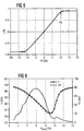
- the strength of the anisotropy field H k was determined from the B-H loop recorded by a B-H loop tracer, as shown in Figure 5.
- the samples were excited (driven) to resonate at different bias fields by ac-field bursts of about 18 mOe peak amplitude.
- the on-time of the bursts was about one-tenth of the 60 Hz repetition rate, i.e., about 1.6 mm.
- the resonant amplitudes were measured at 1 ms and 2 ms after an individual burst was terminated, using a close-coupled receiver coil of 100 tums.
- the values A1 indicate the signal amplitude at 1 ms after termination of the burst.
- A1 ⁇ N • W • H ac wherein N is the number of turns of the receiver coil, W is the width of the resonator and H ac is the field strength of the excitation (driving) field. The specific combination of these factors which produces A1 is not significant.
- the frequency versus bias slope was determined between 6 and 7 Oe, and the frequency shift upon deactivation was determined by observing the resonant frequency at 6.5 Oe (activated state) and 2 Oe (upper field limit for the deactivated state), and was calculated as the difference between the resonant frequencies at these field strengths.
- Figures 5 through 8 illustrate the typical characteristics of the magnetic and magnetoelastic properties of a resonator made in accordance with the present invention. These curves are for a Fe 24 Co 18 Ni 40 Si 2 B 16 alloy annealed for about 6 s at 360°C in a transverse field. The sample is 6 mm wide and 24 ⁇ m thick. The length was adjusted to 37.1 mm in order to produce a resonant frequency at precisely 58 kHz at 6.5 Oe.
- the annealing conditions were intentionally selected so that the slope between 6 and 7 Oe bias field is at the upper limit of about 700 Hz/Oe and the anisotropy field H k is around the lower limit of about 10 Oe. Changing the annealing temperature to about 340°C would readily yield a more desirable slope of about 600 Hz/Oe at the same annealing speed.
- Figure 5 shows the B-H loop recorded at 50 Hz.
- the dashed line shown in Figure 5 is an ideal loop for a transverse anisotropy, for defining the anisotropy field H k , and demonstrating the linearity of the loop up to approaching magnetic saturation, which occurs at about 10 Oe.
- Figure 6 shows the resonant frequency and the resonant amplitude A1 of this sample as a function of the bias field.
- Figure 7 shows the relationship between the Q value of this sample versus the bias field.
- the resonator In the activated state, the resonator is biased with a magnetic field which is typically between 6 and 7 Oe. At this bias field strength, the resonator exhibits a high amplitude and a Q which is lower than 550. Typically the amplitude under the above-described test conditions will be at a minimum of about 40 mV, in order to provide good detection in an interrogation system as described above.
- the marker is deactivated by decreasing or eliminating the bias field, thereby increasing the resonant frequency, decreasing the amplitude, and increasing the Q. This is accomplished by demagnetizing the bias element 4.
- the resonant frequency depends upon the bias field strength.
- typical variations of the bias field from a target value can be about +/- 0.5 Oe. These variations can arise from different orientations of the marker with respect to the earth's magnetic field, or from the property scatter of the bias element 4.
- the resonator material itself is also subject to scatter, and may not exhibit exactly the target frequency at the target bias field. For these reasons, the resonator 3 must be designed so that its frequency vs. bias slope is not too steep.
- Figure 8 shows the resonant amplitude A1 against the frequency at a bias field of 6.5 Oe, and bias fields 0.5 Oe above and below this target value. Due to the finite bandwidth of the resonant curve (which is largely determined by the on-time of the ac-bursts and also by the resonator Q), the resonator 3 still shows a sufficient signal at the transmitter frequency of 58 kHz, even if the resonant frequency is not precisely hit. As illustrated in Figure 8, the resonant signal A1 is still above approximately 40 mV if the frequency variation is about 700 Hz per 1 Oe variation in the bias field. Larger frequency variations are disadvantageous, smaller frequency variations are favorable.
- the resonant curves of the activated marker should not be separated by more than about one-half of their amplitude bandwidth.
- is preferably below about 700 Hz/Oe.
- the variation of the frequency with the bias field is also one of the reasons why the bias field for activating the resonator 3 is between about 6 and 7 Oe.
- the bias field should be chosen so that the earth's magnetic field is at least less than approximately 10% of the field strength of the bias element 4.
- H b There is also an upper limit for H b . More bias magnet material for the bias element 4 is needed in order to produce a larger H b , which makes the marker more expensive.
- a larger H b results in a larger magnetic attractive force between the bias element 4 and the resonator 3, which may introduce significant damping dependent on the orientation of the marker (magnetic attractive force vs. gravity).
- the optimum bias fields are thus located in approximately the 6 -7 Oe range.
- the resonant frequency of the resonator 3 should change significantly when the marker is deactivated by removing the bias field H b .
- the overlap of the resonant curves at different bias fields are sufficiently separated when the resonant frequency changes by at least about 1.2 kHz upon decreasing the bias field.
- the two curves are given for the deactivated state, and correspond to two different levels of the ac-burst field.
- the dashed curve is the ac field strength at 18 mOe, typically used in aforementioned standard test, while the other curve (for the deactivated state) corresponds to an increased drive field level as may occur in the interrogation zone of a magnetomechanical surveillance system close to the transmitter coil 6.
- the curve shown for the activated state was taken at the standard drive field strength of 18 mOe.
- the deactivation is achieved by demagnetizing the bias element 4.
- a "demagnetized" bias element 4 may still exhibit a small magnetization, thereby producing a bias field H b of about 2 Oe. Therefore, as a testing criterion, the frequency shift of the resonant frequency at 2 Oe compared against the resonant frequency at 6.5 Oe should be at least 1.2 kHz in order to guarantee that the resonator 3 will be properly deactivateable.
- Figure 10 provides further information as to why a resonator Q between about 200 and 550 is particularly well-suited for the resonator 3.
- “infinite” means a time scale much larger than Q/n f r (typically a few milliseconds).
- the amplitude A ⁇ is the resonator amplitude which is measured if the resonator is excited in a continuous mode, rather than in a burst mode as is used in a magnetomechanical surveillance system.
- the magnetoacoustic properties react sensitively to the composition and to the annealing conditions. Material scatter, i.e., slight deviations from the target compositions, can be compensated by changing the annealing parameters. It is highly desirable to undertake this in an automated manner, i.e., to measure the resonator properties during annealing and to adjust the annealing parameters accordingly. It is not initially clear, however, how one can conclude or estimate what the magnetoacoustic properties of a short resonator will be from observation of the properties of a continuous ribbon.
- the above data shows that the anisotropy field of the resonator is closely correlated to the resonator properties.
- the anisotropy field of the resonator and the anisotropy field measured on a continuous ribbon only differ by the demagnetizing field.
- the anisotropy field H k of the continuous ribbon can be monitored, as well as its width and thickness, and from that the anisotropy field H k of the resonator can be calculated by adding the demagnetizing effect. This allows adjustment of the annealing parameters, for example, the annealing speed, in an automated manner, which results in highly reproducible properties of the annealed resonator material.
Abstract
Description
15 < a < 30
79 < a + b + c < 85
b > 12
30 < c < 50
with x and y comprising the remainder, so that a + b + c + x + y = 100, and wherein the activated resonator has a
| Constituents (at%) | H k | |df r /dH b | | Q | A1 | |||||
| Sample Nr | Fe | Co | Ni | Si | B | (Oe) | (Hz/Oe) | (mV) | |
| I.A | 40 | 38 | Mo 4 | 18 | 7.0 | 300 | 85 | 7 | |
| I.B | 76 | 12 | 12 | 7.4 | 190 | 169 | 9 | ||
| I.C | 41.5 | 41.5 | 1 | 16 | 11.3 | 1376 | 197 | 68 | |
| I.D | 47.4 | 31.6 | 2 | 19 | 15.6 | 1011 | 325 | 71 | |
| I.E | 52 | 30 | 2 | 16 | 13.9 | 1246 | 236 | 80 | |
| I.F | 57 | 25 | 2 | 16 | 13.7 | 1493 | 229 | 84 | |
| I.G | 58 | 25 | 1 | 16 | 14.6 | 1331 | 223 | 86 | |
| I.H | 61.5 | 21.5 | 1 | 16 | 19.1 | 981 | 337 | 73 | |
| I.I | 62 | 20 | 2 | 16 | 13.2 | 1718 | 137 | 60 | |
| I.J | 66 | 18 | 1 | 15 | 18.7 | 1084 | 236 | 74 | |
| I.K | 4.7 | 72.8 | 5.5 | 17 | no magnetoelastic resonance | ||||
| I.L | 7.5 | 57 | 17 | 2 | 16.5 | no magnetoelastic resonance | |||
| I.M | 6.8 | 38.2 | 40 | 13 | 2 | no magnetoelastic resonance | |||
| I. N | 9 | 10 | 64 | 1 | 16 | no magnetoelastic resonance |
| Constituents (at%) | H k | Q | A1 | |||||
| Sample Nr | Fe | Co | Ni | Si | B | (Oe) | (mV) | |
| II.1 | 18 | 65 | 1 | 16 | 11.1 | 281 | 71 | |
| II.2 | 24 | 55 | 6 | 15 | 11.6 | 385 | 79 | |
| II.3 | 26 | 57 | 1 | 16 | 14.5 | 438 | 83 | |
| II.4 | 34 | 49 | 1 | 16 | 16.9 | 509 | 84 | |
| II.5 | 37 | 45 | 3 | 15 | 16.9 | 550 | 84 | |
| II.6 | 37 | 45 | 5 | 13 | 16.8 | 550 | 84 | |
| II.7 | 38 | 45 | 1 | 16 | 18.7 | 555 | 82 | |
| II.8 | 41 | 41 | 2 | 16 | 19.5 | 586 | 82 | |
| II.9 | 41.5 | 41.5 | 1 | 16 | 17.8 | 554 | 85 | |
| II.10 | 43.5 | 39.5 | 1 | 16 | 18.8 | 560 | 83 | |
| II.11 | 45 | 38 | 1 | 16 | 21.2 | 598 | 80 | |
| II.12 | 45 | 35 | 3 | 1 | 16 | 20.4 | 595 | 81 |
| UNSUITABLE EXAMPLES | ||||||||
| II.A | 46.5 | 31.5 | 5 | 1 | 16 | 20.4 | 612 | 81 |
| II.B | 49 | 31.5 | 2.5 | 1 | 16 | 21.0 | 627 | 81 |
| II.C | 51.5 | 31.5 | 1 | 16 | 21.7 | 636 | 81 |
| Sample Nr. | Fe | Co | Ni | Si | B | H k (Oe) | Q | A1 (mV) |
| III.1 | 19 | 22 | 42 | 1 | 16 | 10.1 | 365 | 65 |
| III.2 | 21 | 20 | 42 | 1 | 16 | 10.7 | 418 | 68 |
| III.3 | 21 | 20 | 41 | 2 | 16 | 10.4 | 435 | 67 |
| III.4 | 21.5 | 41.5 | 20 | 1 | 16 | 11.3 | 321 | 72 |
| III.5 | 23 | 20 | 40 | 1 | 16 | 11.7 | 403 | 73 |
| III.6 | 24 | 16 | 43 | 1 | 16 | 11.6 | 456 | 71 |
| III.7 | 24 | 16 | 42 | 2 | 16 | 11.3 | 462 | 71 |
| III.8 | 24 | 18 | 40 | 2 | 16 | 11.4 | 459 | 72 |
| III.9 | 24 | 22 | 35 | 3 | 16 | 11.6 | 471 | 74 |
| III.10 | 25 | 20 | 38 | 1 | 16 | 12.2 | 485 | 73 |
| III.11 | 25 | 20 | 37 | 2 | 16 | 12.0 | 505 | 73 |
| III.12 | 26.5 | 41.5 | 15 | 1 | 16 | 13.9 | 433 | 80 |
| III.13 | 27 | 27 | 27 | 3 | 16 | 13.2 | 502 | 78 |
| III.14 | 28 | 20 | 34 | 2 | 16 | 13.2 | 528 | 76 |
| III.15 | 28 | 16 | 38 | 2 | 16 | 12.8 | 546 | 75 |
| III.16 | 28.5 | 31.5 | 20 | 4 | 16 | 13.6 | 540 | 81 |
| III.17 | 29 | 27 | 27 | 1 | 16 | 13.9 | 479 | 78 |
| III.18 | 29.5 | 39.5 | 10 | 6 | 15 | 13.0 | 476 | 80 |
| III.19 | 30.5 | 31.5 | 20 | 2 | 16 | 14.7 | 526 | 81 |
| III.20 | 31.5 | 41.5 | 10 | 1 | 16 | 16.4 | 498 | 81 |
| III.21 | 31.5 | 31.5 | 20 | 1 | 16 | 15.4 | 513 | 80 |
| III.22 | 31.5 | 31.5 | 20 | 1 | 16 | 15.2 | 521 | 80 |
| III.23 | 32.5 | 20 | 30 | 1 | 16.5 | 15.2 | 570 | 77 |
| III.24 | 35 | 17.5 | 30 | 1 | 16.5 | 15.9 | 597 | 77 |
| III.25 | 36 | 13 | 34 | 1 | 16 | 16.3 | 590 | 76 |
| III.26 | 36.5 | 36.5 | 10 | 1 | 16 | 18.2 | 544 | 80 |
| III.27 | 37.7 | 15.3 | 30 | 1.3 | 15.7 | 16.5 | 595 | 75 |
| III.28 | 40 | 15 | 30 | 1 | 14 | 17.7 | 591 | 75 |
| III.29 | 41 | 31 | 10 | 1 | 17 | 18.2 | 588 | 82 |
| III.30 | 41 | 31 | 10 | 2 | 16 | 18.5 | 595 | 81 |
| III.31 | 41.5 | 31.5 | 10 | 1 | 16 | 18.7 | 587 | 81 |
| UNSUITABLE EXAMPLES | ||||||||
| III.A | 41 | 16 | 25 | 2 | 16 | 17.0 | 662 | 81 |
| III.B | 42 | 13 | 27.5 | 1 | 16.5 | 17.7 | 646 | 77 |
| III.C | 43 | 21 | 18 | 2 | 16 | 18.0 | 635 | 80 |
| III.D | 43 | 25 | 14 | 2 | 16 | 18.6 | 646 | 82 |
| III.E | 44 | 16 | 22 | 2 | 16 | 18.3 | 657 | 79 |
| III.F | 44.5 | 13 | 25 | 1.5 | 16 | 17.8 | 660 | 79 |
| III.G | 45 | 25 | 12 | 2 | 16 | 19.0 | 657 | 83 |
| III.H | 46 | 21 | 15 | 2 | 16 | 18.6 | 636 | 81 |
| III.I | 46 | 26 | 10 | 2 | 16 | 19.1 | 647 | 83 |
| III.J | 47 | 10 | 25 | 2 | 16 | 18.6 | 674 | 78 |
| III.K | 47 | 10 | 25 | 2 | 16 | 18.0 | 678 | 79 |
| III.L | 49.5 | 13 | 20 | 1.5 | 16 | 194 | 669 | 79 |
| III.M | 51 | 21 | 10 | 2 | 16 | 19.9 | 675 | 83 |
Claims (18)
- A resonator for use in a marker in a magnetomechanical electronic article surveillance system, said resonator comprising an annealed amorphous magnetostrictive alloy having a composition FeaCobNicSixBy, wherein a, b, c, x and y are at % and a+b+c+x+y=100, and selected from the group of alloys in which:-i) a ranges from 15 to 30, b is at least 12, c ranges from 30 to 50, and 79<a+b+c<85; orii) a is at least 15 and b is at least 32; oriii) a ranges between 15 and 40; oriv) a ranges between 15 and 42, b ranges between 18 and 32, and c is at least 10; or a is at least 15, b is at least 12, and c is between 30 and 53
and having a linear B-H loop up to a minimum field strength of 8 Oe, a quality Q between 100 and 600, an anisotropy field Hk of at least 10 Oe and, when excited to resonate in the presence of a bias magnetic field Hb, producing a signal at a mechanical resonant frequency fr having an amplitude at approximately 1 ms after excitation which is no more than 15 dB below an amplitude of said signal immediately after excitation and an amplitude at approximately 7 ms after excitation which is at least 15 dB below said amplitude at 1 ms after excitation and the alloy being annealed at a temperature range between 300 °C and 400 °C for less than one minute in a transverse magnetic field. - A resonator as claimed in Claim 1, wherein the alloy is of group ii) and the cobalt content is at least 43at% and at most 55at%.
- A resonator as claimed in Claim 0, wherein the alloy is of group iii), the iron content is at most 30at%, the cobalt content is at least 15at%, and the nickel content is at least 10at%.
- A resonator as claimed in Claim 0, wherein the alloy is of group iii), the cobalt content is between 12 and 20at% and the nickel content is between 30 and 45at%.
- A resonator as claimed in Claim 1, in which the alloy is selected from the group of alloys having the compositions (in at%):-
Fe Co Ni Si B 18 65 1 16 24 55 6 15 26 57 1 16 34 49 1 16 37 45 3 15 37 45 5 13 38 45 1 16 41 41 2 16 41.5 41.5 1 16 43.5 39.5 1 16 45 38 1 16 45 35 3 1 16 19 22 42 1 16 21 20 42 1 16 21 20 41 2 16 21.5 41.5 20 1 16 23 20 40 1 16 24 16 43 1 16 24 16 42 2 16 24 18 40 2 16 24 22 35 3 16 25 20 38 1 16 25 20 37 2 16 26.5 41.5 15 1 16 27 27 27 3 16 28 20 34 2 16 28 16 38 2 16 28.5 31.5 20 4 16 29 27 27 1 16 29.5 39.5 10 6 15 30.5 31.5 20 2 16 31.5 41.5 10 1 16 31.5 31.5 20 1 16 31.5 31.5 20 1 16 32.5 20 30 1 16.5 35 17.5 30 1 16.5 36 13 34 1 16 36.5 36.5 10 1 16 37.7 15.3 30 1.3 15.7 40 15 30 1 14 41 31 10 1 17 41 31 10 2 16 41.5 31.5 10 1 16 - A resonator as claimed in Claim 1 wherein said mechanical resonant frequency fr changes dependent on the field strength of said bias field Hb, and wherein |dfr /dHb| is less than 700 Hz/Oe with Hb between 6 and 7 Oe.
- A resonator as claimed in Claim 6 wherein |dfr/dHb| is between 550 and 650 Hz/Oe.
- A resonator as claimed in any preceding claim wherein the resonant frequency fr changes by at least 1.2 kHz when said bias field Hb is removed.
- A resonator as claimed in any preceding claim having a quality Q which is greater than 200.
- A resonator as claimed in any preceding claim having a quality Q which is less than 550.
- A resonator as claimed in Claim 1 having a width of approximately 6mm (one-half inch), and wherein said annealed amorphous magnetostrictive alloy has a composition
- A resonator as claimed in Claim 1 having a width of approximately 6 mm, and wherein said annealed amorphous magnetostrictive alloy has a composition Fe24Co18Ni40Si2B16.
- A resonator as claimed in any preceding claim wherein said resonator produces a signal having amplitude of at least 40 mV at approximately 1 ms after excitation of said resonator.
- A marker for use in a magnetomechanical electronic article surveillance system, said marker comprising:a bias element which produces a bias magnetic field of up to 10 Oe;a resonator as claimed in any preceding claim and disposed adjacent said bias element; anda housing encapsulating said bias element and said resonator.
- A magnetomechanical electronic article surveillance system comprising:i) a marker as claimed in claim 14;ii) transmitter means for exciting said marker for causing said resonator to mechanically resonate and to emit said signal at a resonant frequency;iii) receiver means for receiving and integrating said signal from said resonator at said resonant frequency;iv) synchronisation means connected to said transmitter means and to said receiver means for activating said receiver means for receiving and integrating said signal at said resonant frequency from said resonator in a first detection window beginning at approximately 0.4 ms after excitation of said resonator by said transmitter means and in a second detection window beginning at approximately 7 ms after excitation of said resonator by said transmitter means; andv) an alarm, said receiver means comprising means for triggering said alarm if said signal at said resonant frequency from said resonator integrated in said second detection window is substantially below said signal at said resonant frequency from said resonator integrated in said first detection window.
- A method of making a resonator for use in a magnetomechanical electronic article surveillance system, comprising the steps of:providing an amorphous magnetostrictive alloy having a composition as specified for the resonator of Claim 1; andannealing said amorphous magnetostrictive alloy in a transverse magnetic field and at a temperature in a range between 300°C. and 400° C for less than one minute.
- A method of making a marker for use in a magnetomechanical electronic article surveillance system, comprising the steps of:making a resonator by the method of Claim 16;placing said resonator adjacent a magnetised ferromagnetic bias element; andencapsulating said resonator and said bias element in a housing.
- A method of making a marker as claimed in Claim 17 comprising the additional step of magnetising said bias element for producing a bias field having a strength up to 10 Oe.
Priority Applications (2)
| Application Number | Priority Date | Filing Date | Title |
|---|---|---|---|
| DK05010323T DK1562160T3 (en) | 1997-07-09 | 1998-07-01 | Amorphous magnetostrictive alloy and an electronic product monitoring system using it |
| EP05010323A EP1562160B1 (en) | 1997-07-09 | 1998-07-01 | Amorphous magnetostrictive alloy and an electronic article surveillance system employing same |
Applications Claiming Priority (3)
| Application Number | Priority Date | Filing Date | Title |
|---|---|---|---|
| US890723 | 1978-03-20 | ||
| US08/890,723 US5841348A (en) | 1997-07-09 | 1997-07-09 | Amorphous magnetostrictive alloy and an electronic article surveillance system employing same |
| PCT/EP1998/004053 WO1999013442A1 (en) | 1997-07-09 | 1998-07-01 | Amorphous magnetostrictive alloy and an electronic article surveillance system employing same |
Related Child Applications (2)
| Application Number | Title | Priority Date | Filing Date |
|---|---|---|---|
| EP05010323A Division EP1562160B1 (en) | 1997-07-09 | 1998-07-01 | Amorphous magnetostrictive alloy and an electronic article surveillance system employing same |
| EP05010323.3 Division-Into | 2005-05-12 |
Publications (2)
| Publication Number | Publication Date |
|---|---|
| EP0996942A1 EP0996942A1 (en) | 2000-05-03 |
| EP0996942B1 true EP0996942B1 (en) | 2005-09-07 |
Family
ID=25397063
Family Applications (2)
| Application Number | Title | Priority Date | Filing Date |
|---|---|---|---|
| EP98939591A Expired - Lifetime EP0996942B1 (en) | 1997-07-09 | 1998-07-01 | Amorphous magnetostrictive alloy and an electronic article surveillance system employing same |
| EP05010323A Expired - Lifetime EP1562160B1 (en) | 1997-07-09 | 1998-07-01 | Amorphous magnetostrictive alloy and an electronic article surveillance system employing same |
Family Applications After (1)
| Application Number | Title | Priority Date | Filing Date |
|---|---|---|---|
| EP05010323A Expired - Lifetime EP1562160B1 (en) | 1997-07-09 | 1998-07-01 | Amorphous magnetostrictive alloy and an electronic article surveillance system employing same |
Country Status (10)
| Country | Link |
|---|---|
| US (1) | US5841348A (en) |
| EP (2) | EP0996942B1 (en) |
| JP (1) | JP4101307B2 (en) |
| KR (1) | KR100582580B1 (en) |
| AT (2) | ATE304197T1 (en) |
| DE (2) | DE69834282T2 (en) |
| DK (1) | DK1562160T3 (en) |
| ES (1) | ES2263146T3 (en) |
| PT (1) | PT1562160E (en) |
| WO (1) | WO1999013442A1 (en) |
Families Citing this family (19)
| Publication number | Priority date | Publication date | Assignee | Title |
|---|---|---|---|---|
| US6011475A (en) * | 1997-11-12 | 2000-01-04 | Vacuumschmelze Gmbh | Method of annealing amorphous ribbons and marker for electronic article surveillance |
| US6254695B1 (en) * | 1998-08-13 | 2001-07-03 | Vacuumschmelze Gmbh | Method employing tension control and lower-cost alloy composition annealing amorphous alloys with shorter annealing time |
| US6199309B1 (en) * | 1998-10-06 | 2001-03-13 | Contempo Card Company, Inc. | Merchandising markers accomodating anti-theft sensor |
| US6181249B1 (en) * | 1999-01-07 | 2001-01-30 | Sensormatic Electronics Corporation | Coil driving circuit for EAS marker deactivation device |
| US6359563B1 (en) * | 1999-02-10 | 2002-03-19 | Vacuumschmelze Gmbh | ‘Magneto-acoustic marker for electronic article surveillance having reduced size and high signal amplitude’ |
| US6645314B1 (en) | 2000-10-02 | 2003-11-11 | Vacuumschmelze Gmbh | Amorphous alloys for magneto-acoustic markers in electronic article surveillance having reduced, low or zero co-content and method of annealing the same |
| KR20030013068A (en) * | 2001-08-07 | 2003-02-14 | 정한영 | Apparatus and method for deactivating magnetic markers in an electromagnetic article surveillance sytem |
| US6783072B2 (en) * | 2002-02-01 | 2004-08-31 | Psc Scanning, Inc. | Combined data reader and electronic article surveillance (EAS) system |
| US6854647B2 (en) * | 2002-02-01 | 2005-02-15 | Ncr Corporation | Checkout device including integrated barcode reader, scale, and EAS system |
| EP2287817B1 (en) * | 2002-02-01 | 2012-05-23 | Datalogic Adc, Inc. | Systems and methods for data reading and EAS tag sensing and deactivation at retail checkout |
| US6749695B2 (en) * | 2002-02-08 | 2004-06-15 | Ronald J. Martis | Fe-based amorphous metal alloy having a linear BH loop |
| US7527198B2 (en) * | 2002-03-18 | 2009-05-05 | Datalogic Scanning, Inc. | Operation monitoring and enhanced host communications in systems employing electronic article surveillance and RFID tags |
| US6830634B2 (en) * | 2002-06-11 | 2004-12-14 | Sensormatic Electronics Corporation | Method and device for continuous annealing metallic ribbons with improved process efficiency |
| US7585459B2 (en) * | 2002-10-22 | 2009-09-08 | Höganäs Ab | Method of preparing iron-based components |
| US7619527B2 (en) * | 2005-02-08 | 2009-11-17 | Datalogic Scanning, Inc. | Integrated data reader and electronic article surveillance (EAS) system |
| DE102005062016A1 (en) * | 2005-12-22 | 2007-07-05 | Vacuumschmelze Gmbh & Co. Kg | Deposit goods e.g. tin security mark, has sensor strips parameter of which indicates magnetizing force, and the permeability is changed to specified factor within specified range by magnetizing force |
| DE102006047022B4 (en) | 2006-10-02 | 2009-04-02 | Vacuumschmelze Gmbh & Co. Kg | Display element for a magnetic anti-theft system and method for its production |
| JP2008097459A (en) * | 2006-10-13 | 2008-04-24 | Takaya Corp | Device for monitoring electronic object |
| WO2017221099A1 (en) | 2016-06-23 | 2017-12-28 | 3M Innovative Properties Company | Magneto-mechanical marker with enhanced frequency stability and signal strength |
Family Cites Families (9)
| Publication number | Priority date | Publication date | Assignee | Title |
|---|---|---|---|---|
| US4268325A (en) * | 1979-01-22 | 1981-05-19 | Allied Chemical Corporation | Magnetic glassy metal alloy sheets with improved soft magnetic properties |
| US4484184A (en) * | 1979-04-23 | 1984-11-20 | Allied Corporation | Amorphous antipilferage marker |
| US4510489A (en) * | 1982-04-29 | 1985-04-09 | Allied Corporation | Surveillance system having magnetomechanical marker |
| US4667185A (en) * | 1985-12-06 | 1987-05-19 | Minnesota Mining And Manufacturing Company | Wireless synchronization system for electronic article surveillance system |
| US5252144A (en) * | 1991-11-04 | 1993-10-12 | Allied Signal Inc. | Heat treatment process and soft magnetic alloys produced thereby |
| US5568125A (en) * | 1994-06-30 | 1996-10-22 | Sensormatic Electronics Corporation | Two-stage annealing process for amorphous ribbon used in an EAS marker |
| US5469140A (en) * | 1994-06-30 | 1995-11-21 | Sensormatic Electronics Corporation | Transverse magnetic field annealed amorphous magnetomechanical elements for use in electronic article surveillance system and method of making same |
| US5628840A (en) * | 1995-04-13 | 1997-05-13 | Alliedsignal Inc. | Metallic glass alloys for mechanically resonant marker surveillance systems |
| US5539380A (en) * | 1995-04-13 | 1996-07-23 | Alliedsignal Inc. | Metallic glass alloys for mechanically resonant marker surveillance systems |
-
1997
- 1997-07-09 US US08/890,723 patent/US5841348A/en not_active Expired - Lifetime
-
1998
- 1998-07-01 PT PT05010323T patent/PT1562160E/en unknown
- 1998-07-01 AT AT98939591T patent/ATE304197T1/en not_active IP Right Cessation
- 1998-07-01 EP EP98939591A patent/EP0996942B1/en not_active Expired - Lifetime
- 1998-07-01 ES ES05010323T patent/ES2263146T3/en not_active Expired - Lifetime
- 1998-07-01 AT AT05010323T patent/ATE323925T1/en not_active IP Right Cessation
- 1998-07-01 WO PCT/EP1998/004053 patent/WO1999013442A1/en active IP Right Grant
- 1998-07-01 JP JP51497999A patent/JP4101307B2/en not_active Expired - Lifetime
- 1998-07-01 KR KR1020007000165A patent/KR100582580B1/en not_active IP Right Cessation
- 1998-07-01 EP EP05010323A patent/EP1562160B1/en not_active Expired - Lifetime
- 1998-07-01 DE DE69834282T patent/DE69834282T2/en not_active Expired - Lifetime
- 1998-07-01 DK DK05010323T patent/DK1562160T3/en active
- 1998-07-01 DE DE69831492T patent/DE69831492T2/en not_active Expired - Lifetime
Also Published As
| Publication number | Publication date |
|---|---|
| DE69834282T2 (en) | 2007-04-12 |
| US5841348A (en) | 1998-11-24 |
| ATE304197T1 (en) | 2005-09-15 |
| EP0996942A1 (en) | 2000-05-03 |
| DE69834282D1 (en) | 2006-05-24 |
| PT1562160E (en) | 2006-08-31 |
| EP1562160A1 (en) | 2005-08-10 |
| ATE323925T1 (en) | 2006-05-15 |
| WO1999013442A1 (en) | 1999-03-18 |
| KR100582580B1 (en) | 2006-05-24 |
| EP1562160B1 (en) | 2006-04-19 |
| ES2263146T3 (en) | 2006-12-01 |
| KR20010021607A (en) | 2001-03-15 |
| DK1562160T3 (en) | 2006-08-21 |
| JP4101307B2 (en) | 2008-06-18 |
| DE69831492T2 (en) | 2006-06-29 |
| JP2002510417A (en) | 2002-04-02 |
| DE69831492D1 (en) | 2005-10-13 |
Similar Documents
| Publication | Publication Date | Title |
|---|---|---|
| EP0996942B1 (en) | Amorphous magnetostrictive alloy and an electronic article surveillance system employing same | |
| EP0996759B1 (en) | Amorphous magnetostrictive alloy with low cobalt content and method for annealing same | |
| US5469140A (en) | Transverse magnetic field annealed amorphous magnetomechanical elements for use in electronic article surveillance system and method of making same | |
| US5729200A (en) | Magnetomechanical electronic article surveilliance marker with bias element having abrupt deactivation/magnetization characteristic | |
| EP0820534B1 (en) | Metallic glass alloys for mechanically resonant marker surveillance systems | |
| EP0696784A1 (en) | Magnetomechanical article surveillance marker with a tunable resonant frequency | |
| US6181245B1 (en) | Magnetomechanical electronic article surveillance marker with bias element having abrupt deactivation/magnetization characteristic | |
| CA2319334C (en) | Redistributing magnetic charge in bias element for magnetomechanical eas marker | |
| CA2492950C (en) | Transverse magnetic field annealed amorphous magnetomechanical elements for use in electronic article surveillance system and method of making same | |
| AU738871B2 (en) | Transverse magnetic field annealed amorphous magnetomechanical elements for use in electronic article surveillance system and method of making same | |
| AU711803B2 (en) | Transverse magnetic field annealed amorphous magnetomechanical elements for use in electronic article surveillance system and method of making same | |
| CA2149380C (en) | Magnetomechanical article surveillance marker with a tunable resonant frequency | |
| EP0895208A2 (en) | Transverse magnetic field annealed amorphous magnetomechanical elements for use in electronic article surveillance system and method of making same |
Legal Events
| Date | Code | Title | Description |
|---|---|---|---|
| PUAI | Public reference made under article 153(3) epc to a published international application that has entered the european phase |
Free format text: ORIGINAL CODE: 0009012 |
|
| 17P | Request for examination filed |
Effective date: 20000201 |
|
| AK | Designated contracting states |
Kind code of ref document: A1 Designated state(s): AT BE CH CY DE DK ES FI FR GB GR IE IT LI LU MC NL PT SE |
|
| 17Q | First examination report despatched |
Effective date: 20030516 |
|
| GRAP | Despatch of communication of intention to grant a patent |
Free format text: ORIGINAL CODE: EPIDOSNIGR1 |
|
| GRAS | Grant fee paid |
Free format text: ORIGINAL CODE: EPIDOSNIGR3 |
|
| GRAA | (expected) grant |
Free format text: ORIGINAL CODE: 0009210 |
|
| RAP1 | Party data changed (applicant data changed or rights of an application transferred) |
Owner name: VACUUMSCHMELZE GMBH & CO. KG |
|
| AK | Designated contracting states |
Kind code of ref document: B1 Designated state(s): AT BE CH CY DE DK ES FI FR GB GR IE IT LI LU MC NL PT SE |
|
| PG25 | Lapsed in a contracting state [announced via postgrant information from national office to epo] |
Ref country code: NL Free format text: LAPSE BECAUSE OF FAILURE TO SUBMIT A TRANSLATION OF THE DESCRIPTION OR TO PAY THE FEE WITHIN THE PRESCRIBED TIME-LIMIT Effective date: 20050907 Ref country code: LI Free format text: LAPSE BECAUSE OF FAILURE TO SUBMIT A TRANSLATION OF THE DESCRIPTION OR TO PAY THE FEE WITHIN THE PRESCRIBED TIME-LIMIT Effective date: 20050907 Ref country code: IT Free format text: LAPSE BECAUSE OF FAILURE TO SUBMIT A TRANSLATION OF THE DESCRIPTION OR TO PAY THE FEE WITHIN THE PRESCRIBED TIME-LIMIT;WARNING: LAPSES OF ITALIAN PATENTS WITH EFFECTIVE DATE BEFORE 2007 MAY HAVE OCCURRED AT ANY TIME BEFORE 2007. THE CORRECT EFFECTIVE DATE MAY BE DIFFERENT FROM THE ONE RECORDED. Effective date: 20050907 Ref country code: FI Free format text: LAPSE BECAUSE OF FAILURE TO SUBMIT A TRANSLATION OF THE DESCRIPTION OR TO PAY THE FEE WITHIN THE PRESCRIBED TIME-LIMIT Effective date: 20050907 Ref country code: CH Free format text: LAPSE BECAUSE OF FAILURE TO SUBMIT A TRANSLATION OF THE DESCRIPTION OR TO PAY THE FEE WITHIN THE PRESCRIBED TIME-LIMIT Effective date: 20050907 Ref country code: BE Free format text: LAPSE BECAUSE OF FAILURE TO SUBMIT A TRANSLATION OF THE DESCRIPTION OR TO PAY THE FEE WITHIN THE PRESCRIBED TIME-LIMIT Effective date: 20050907 Ref country code: AT Free format text: LAPSE BECAUSE OF FAILURE TO SUBMIT A TRANSLATION OF THE DESCRIPTION OR TO PAY THE FEE WITHIN THE PRESCRIBED TIME-LIMIT Effective date: 20050907 |
|
| REG | Reference to a national code |
Ref country code: GB Ref legal event code: FG4D |
|
| REG | Reference to a national code |
Ref country code: CH Ref legal event code: EP |
|
| REG | Reference to a national code |
Ref country code: IE Ref legal event code: FG4D |
|
| REF | Corresponds to: |
Ref document number: 69831492 Country of ref document: DE Date of ref document: 20051013 Kind code of ref document: P |
|
| PG25 | Lapsed in a contracting state [announced via postgrant information from national office to epo] |
Ref country code: SE Free format text: LAPSE BECAUSE OF FAILURE TO SUBMIT A TRANSLATION OF THE DESCRIPTION OR TO PAY THE FEE WITHIN THE PRESCRIBED TIME-LIMIT Effective date: 20051207 Ref country code: GR Free format text: LAPSE BECAUSE OF FAILURE TO SUBMIT A TRANSLATION OF THE DESCRIPTION OR TO PAY THE FEE WITHIN THE PRESCRIBED TIME-LIMIT Effective date: 20051207 Ref country code: DK Free format text: LAPSE BECAUSE OF FAILURE TO SUBMIT A TRANSLATION OF THE DESCRIPTION OR TO PAY THE FEE WITHIN THE PRESCRIBED TIME-LIMIT Effective date: 20051207 |
|
| PG25 | Lapsed in a contracting state [announced via postgrant information from national office to epo] |
Ref country code: ES Free format text: LAPSE BECAUSE OF FAILURE TO SUBMIT A TRANSLATION OF THE DESCRIPTION OR TO PAY THE FEE WITHIN THE PRESCRIBED TIME-LIMIT Effective date: 20051218 |
|
| PG25 | Lapsed in a contracting state [announced via postgrant information from national office to epo] |
Ref country code: PT Free format text: LAPSE BECAUSE OF FAILURE TO SUBMIT A TRANSLATION OF THE DESCRIPTION OR TO PAY THE FEE WITHIN THE PRESCRIBED TIME-LIMIT Effective date: 20060207 |
|
| NLV1 | Nl: lapsed or annulled due to failure to fulfill the requirements of art. 29p and 29m of the patents act | ||
| REG | Reference to a national code |
Ref country code: CH Ref legal event code: PL |
|
| ET | Fr: translation filed | ||
| PLBE | No opposition filed within time limit |
Free format text: ORIGINAL CODE: 0009261 |
|
| STAA | Information on the status of an ep patent application or granted ep patent |
Free format text: STATUS: NO OPPOSITION FILED WITHIN TIME LIMIT |
|
| PG25 | Lapsed in a contracting state [announced via postgrant information from national office to epo] |
Ref country code: MC Free format text: LAPSE BECAUSE OF NON-PAYMENT OF DUE FEES Effective date: 20060731 |
|
| 26N | No opposition filed |
Effective date: 20060608 |
|
| PG25 | Lapsed in a contracting state [announced via postgrant information from national office to epo] |
Ref country code: LU Free format text: LAPSE BECAUSE OF NON-PAYMENT OF DUE FEES Effective date: 20060701 |
|
| PG25 | Lapsed in a contracting state [announced via postgrant information from national office to epo] |
Ref country code: CY Free format text: LAPSE BECAUSE OF FAILURE TO SUBMIT A TRANSLATION OF THE DESCRIPTION OR TO PAY THE FEE WITHIN THE PRESCRIBED TIME-LIMIT Effective date: 20050907 |
|
| PGFP | Annual fee paid to national office [announced via postgrant information from national office to epo] |
Ref country code: IE Payment date: 20120530 Year of fee payment: 15 |
|
| REG | Reference to a national code |
Ref country code: IE Ref legal event code: MM4A |
|
| PG25 | Lapsed in a contracting state [announced via postgrant information from national office to epo] |
Ref country code: IE Free format text: LAPSE BECAUSE OF NON-PAYMENT OF DUE FEES Effective date: 20130701 |
|
| REG | Reference to a national code |
Ref country code: DE Ref legal event code: R082 Ref document number: 69831492 Country of ref document: DE Representative=s name: WESTPHAL, MUSSGNUG & PARTNER PATENTANWAELTE MI, DE |
|
| REG | Reference to a national code |
Ref country code: FR Ref legal event code: PLFP Year of fee payment: 19 |
|
| REG | Reference to a national code |
Ref country code: FR Ref legal event code: PLFP Year of fee payment: 20 |
|
| PGFP | Annual fee paid to national office [announced via postgrant information from national office to epo] |
Ref country code: FR Payment date: 20170727 Year of fee payment: 20 Ref country code: GB Payment date: 20170728 Year of fee payment: 20 |
|
| PGFP | Annual fee paid to national office [announced via postgrant information from national office to epo] |
Ref country code: DE Payment date: 20170929 Year of fee payment: 20 |
|
| REG | Reference to a national code |
Ref country code: DE Ref legal event code: R071 Ref document number: 69831492 Country of ref document: DE |
|
| REG | Reference to a national code |
Ref country code: GB Ref legal event code: PE20 Expiry date: 20180630 |
|
| PG25 | Lapsed in a contracting state [announced via postgrant information from national office to epo] |
Ref country code: GB Free format text: LAPSE BECAUSE OF EXPIRATION OF PROTECTION Effective date: 20180630 |