EP0997680B1 - Fastening device - Google Patents
Fastening device Download PDFInfo
- Publication number
- EP0997680B1 EP0997680B1 EP99115650A EP99115650A EP0997680B1 EP 0997680 B1 EP0997680 B1 EP 0997680B1 EP 99115650 A EP99115650 A EP 99115650A EP 99115650 A EP99115650 A EP 99115650A EP 0997680 B1 EP0997680 B1 EP 0997680B1
- Authority
- EP
- European Patent Office
- Prior art keywords
- adapter
- arrangement according
- fastening arrangement
- wall
- Prior art date
- Legal status (The legal status is an assumption and is not a legal conclusion. Google has not performed a legal analysis and makes no representation as to the accuracy of the status listed.)
- Expired - Lifetime
Links
Images


Classifications
-
- G—PHYSICS
- G01—MEASURING; TESTING
- G01L—MEASURING FORCE, STRESS, TORQUE, WORK, MECHANICAL POWER, MECHANICAL EFFICIENCY, OR FLUID PRESSURE
- G01L19/00—Details of, or accessories for, apparatus for measuring steady or quasi-steady pressure of a fluent medium insofar as such details or accessories are not special to particular types of pressure gauges
- G01L19/0007—Fluidic connecting means
Definitions
- DE 28 49 133 discloses a connecting device for pressure lines, in which a plug-type connection piece can be inserted into a housing opening of a housing provided for this purpose.
- the connector has a plug-in pin on the upper portion of a circumferential groove is formed, which is followed by a circumferential approach, which serves as a stop and predetermines the insertion depth of the connector into the opening of the housing.
- To lock the connector is a base plate having a rail-shaped receptacle for acting as a bolt, in the rail-shaped receptacle reciprocally movable slide.
- the slider in turn has at least one key-shaped opening with an approximately circular portion whose opening diameter corresponds to the diameter of the housing opening and a portion opposite this narrowed. If the connector is inserted with its plug-in pin in the associated housing opening, the slider is moved from the position in which its large diameter portion is aligned with the housing opening, such that the narrowed portion engages with its edges in the groove tangent to the pin, so that the connector is locked and can not be pulled out of the housing opening again. In the locked position, the approach is on the pin in a pocket-like receptacle, which is bounded on the one hand by the top of the housing and on the other hand by the underside of the slider, wherein the adjacent to the stop groove passes through the narrowed portion of the slider.
- the compressed air is filtered, for example, with Oil particles offset or to a desired working pressure regulated.
- the set working pressure can be at a Read off the manometer, as an additional part of an example mounted as a filter-controller device running maintenance device is.
- a fastening device contains the threaded connection fixed to a pressure gauge, in a provided on the service unit threaded hole is screwed, which acts on the pressure to be measured (see Deppert / Stoll "Pneumatic Controls", 10th Edition 1994, pages 38 to 47).
- the assembly and disassembly of the known pressure gauges is relative cumbersome and often leads to unwanted alignments of the manometer, which is a convenient reading of the displayed Prevent pressure values.
- the rotational position of the manometer depends on the possible screw-in depth of the threaded neck which may vary from case to case, so in the final assembly state present orientation usually more random is.
- Another disadvantage is that in an example defective replacement of the manometer the threaded connection to be solved in a complicated way, where not rarely damage to the thread mating occur, in particular if previously corrosive material attacks occurred are. Under certain circumstances, this will make the entire maintenance unit unusable.
- a fastening device for attaching an additional part to a Main body to create, with reduced risk of damage allows easier handling.
- the fastening device is characterized characterized in that the clamping part as with respect to the front Pocket wall separate component is formed, which is to Position the assembly final condition in the receiving pocket in this way lets it be on both sides of the pedestal between the Retaining flange and provided on the additional part, front pocket wall intervenes.
- the additional part may in particular by a measuring and / or display device, for example, a pressure sensor or a pressure gauge, be formed.
- the main part may be in particular to a fluid-carrying device, for example a act for the preparation of compressed air serving maintenance device.
- the attachment of the additional part to the main part takes place with interposition an adapter, which may be an integral part of the main part can, but expediently as a separate component is executed.
- the separate embodiment has the advantage that not different accessories with different Terminal sizes are produced or stored have to.
- One and the same accessory can thus easily to be grown to different main parts, it is just to choose another adapter, its structure and Production is easy.
- He has a spaced arranged to the associated body Holding flange on which the attachment with his as Receiving bag designated pocket-like recess put on until either the edge of the retaining flange or the peripheral surface of the base rests on the additional part and thereby limits the Aufsteckweg.
- Mounting intermediate position can be the additional part with appropriate design of the adapter angularly in a desired orientation, whereupon by pressing the clamping part of the final assembly state is produced, in which the attachment firmly is fixed to the adapter.
- the clamping part engages its fork-like clamping section on each other diametrically opposite sides of the socket between the retaining flange and the recess limiting component the front pocket wall, wherein the retaining flange in Direction of the rear pocket wall is pressed and up overall gives a firm deadlock.
- the adapter is expediently designed as a screw, wherein the base provided with an external thread that can be in one with a complementary one Screw in threaded connection opening of the main part leaves.
- the external thread can with a suitable Sealing material should be coated to automatically when screwing a fluid-tight connection between adapter and Manufacture screw. Is an exchange of the additional part This may be necessary after removing the clamp be removed from the adapter, the adapter on Main body can remain and thus the tightness and Functionality of the threaded connection not impaired becomes.
- the fluid supply to the additional part takes place expediently via a particular coaxial adapter passing through passageway.
- the adapter has a multiple function to hold the Additional part and for guiding the relevant fluid.
- an existing rubber-elastic material placed, preferably in an annular groove of the rear pocket wall of the additional part and / or the adapter.
- the sealing ring can as required have any shapes, including other geometries than a circular geometry are used can reach.
- Optimal twistability and thus variable rotational positioning of the additional part with respect to the adapter results when the retaining flange is over a circular Outside outline has, so to speak, a guide for the rotational movement forms.
- the adapter can also be laterally on the boundary surface support the recess. Especially in this Case can be the receiving pocket at the pocket opening opposite side also be completely open.
- the clamping part can be designed like a slide and in the frame a sliding movement between an assembly and Dismantling of the additional part enabling release and one defining the final assembly state of the additional part Clamping be brought. It can if necessary be stored on the additional part that it is also in the Release position is captively fixed. It is possible but also, the clamping part as a completely separate component in the release position of the additional part is removed and only to obtain the clamping position on Attachment is attached.
- the main part 1 maintenance device shown in compressed air networks for the treatment of Compressed air is used. It concerns in the present Case to a combined filter-controller unit, in the Among other things, the pressure of the compressed air from one by one Pressure source provided output pressure to a lower Working pressure is adjusted.
- the under the Working pressure standing compressed air is among other things in a first fluid channel 2, which via a with a Internally threaded connection opening 3 to the outer surface of the housing of the main part 1 opens.
- the manometer serves to the prevailing in the first fluid channel 2 To record or measure working pressure and a Display device 5 to bring to the display.
- a Display device 5 to bring to the display.
- the manometer serves to the prevailing in the first fluid channel 2 To record or measure working pressure and a Display device 5 to bring to the display.
- the pressure sensor 7 is in the embodiment Part of a fixed in the housing 8 of the additional part 4
- Printed circuit board 12 to which the example with LED and / or display device equipped with LCD display means 5 is connected. At her can be in the present Case read the pressure values of the working pressure.
- An additional electrical connection device 13 can be provided to connect the pressure gauge to an external display and / or control device to connect.
- the generally designated by reference numeral 14 fastening device is particularly suitable for installation a measuring and / or display device on a fluid-carrying Device, for example on a so-called maintenance device. It goes without saying, however, that she is also responsible for mutual attachment of any other parts used can be.
- the fastening device 14 includes a following simplifies only as an adapter 15 designated adapter part, the expediently as with respect to the main part 1 separate Part is executed and in particular solvable on Set body 1. In principle, it would also be one-piece Design with the main part 1 possible, what but at the expense of universal applications would go, so that the separate execution is preferred.
- the adapter 15 has a socket-like base 16, at its one axial end portion in one piece Retaining flange 17 is formed.
- the retaining flange 17 has suitably an annular shape and is coaxial aligned to the base 16, wherein it is radially around the side protrudes beyond the base 16.
- On the base facing away Axial side he defined together with the socket a substantially disc-like contact surface 18, the is axially oriented.
- the base 16 is equipped with connecting means which allow a firm connection with the main body 1. she exist in the embodiment of an external thread 19, so that the adapter 15 is a screw part as a whole and with its base 16 in the connection opening 3 of the Main body 1 screwed tight.
- Fig. 3 has the retaining flange 17 over a circular outer contour. Nevertheless a tight screwing into the connection opening 3 to allow is in the adapter 15, starting from the Bearing surface 18 concentrically a recess 22 introduced which is contoured as a polygon socket and plugging or applying a suitable screwing tool allowed.
- the additional part 4 can be mounted on the main body 1, that its rear side faces the main part 1. in the Area of this back is one with it for simplification as a receiving pocket 23 designated bag-like Well provided, the pocket opening 24 at mounted additional part 4 viewed transversely to the longitudinal axis 25 of the Adapters 15 is oriented.
- FIG. 2 shows the additional part 4 in the finished on the main part. 1 assembled state, what follows as final assembly state is designated. Visible here is the pocket opening 24 perpendicular to the longitudinal axis 25 of the adapter 15 or its base 16 aligned.
- the receiving pocket 23 has one of the rear wall 26 of the additional part 4 formed rear pocket wall 27 and one of these, seen in final assembly state, at a distance in Direction to bulk 1 upstream front pocket wall 28.
- the pocket interior 32 facing inner surface 34 of the lateral pocket wall 33 is at least in the pocket opening 24 directly opposite Area contoured circular arc, wherein the Pocket opening 24 out even with a linear course can, so seen in cross section a suitably U-shaped course of the side pocket wall 33 provided inner surface 34 results.
- the rear wall 26 is extended beyond the pocket opening 24, wherein the pocket opening 24 upstream Area forms a second contact surface 18 '. Further is the height h of the pocket opening 24 is chosen to be slightly larger than the thickness of the retaining flange 17th
- the front pocket wall 28 has an edge to the Pocket opening 24 toward open recess 35, which in the embodiment is contoured circular arc and a Cross-section, which is an at least partial insertion the base 16 allows.
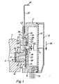
- first Mounting step in the region of the second contact surface 18 'with its rear wall 26 to the provided on the adapter 15 first Investment surface 18 is laid out substantially flat. This condition is shown in Fig. 1.
- the adapter 15 is here with its retaining flange 17 of the pocket opening 24 opposite.
- the additional part 4 according to arrow 36 across the Longitudinal axis 25 of the adapter 15 is displaced and with its receiving pocket 23 attached to the retaining flange 17.
- the retaining flange 17 now projects according to FIGS. 2 and 3 with a part of its circumference, for example with something more than half the circumference, in the pocket interior 32 into it, at the same time the base 16 in the recess 35 intervenes and enforces them.
- the additional part 4 is now practically attached to the adapter 15, wherein the corresponding position referred to as intermediate mounting position be.
- the slip is specified and limited by that the retaining flange 17 with its edge on the inner surface 34th the lateral pocket wall 33 of the receiving pocket 23 for Plant passes, as can be seen from Fig. 2 and 3. There is then still the advantageous possibility, the Additional part 4 relative to the adapter 15 with respect to Twist longitudinal axis 25 and angularly in the desired Align the end position, the aforementioned Inner surface 34 on the radially outward-facing edge slides along the retaining flange 17.
- a clamping part 37 of the fastening device 14 used.
- This clamping part 37 is in the embodiment designed slide-like and can be insert from the outside into a slot-like opening 38, the lateral pocket wall 33 in which the Pocket opening 24 passes through opposite area, and on the one hand to the pocket interior 32 and the other to the outer surface of the housing 8 of the additional part 4 is open.
- the expansion plane of the slot-like opening 38 runs parallel to that of the pocket interior 32, wherein the pocket interior 32 facing the mouth 42 of the opening 38 expediently immediately is provided in addition to the front pocket wall 28.
- the clamping member 37 is in the embodiment as with respect executed the additional part 4 separate component and is expediently in mounting intermediate position befindliches additional part 4 from the outside into the slot-like Opening 38 inserted and inserted so far that it projects into the receiving pocket 23 and with a provided at the front end portion clamping portion 43 between the retaining flange 17 and the front pocket wall 28 comes to rest.
- the clamping part 37 enters the resulting from Fig. 2 and 3 clamping position, in the it is between the retaining flange 17 and the front Pocket wall 28 is supported and at the same time the retaining flange 17 presses against the rear wall of the bag, so that the additional part 4 fixed to the retaining flange 17 of the adapter 15 is clamped or jammed.
- the desired clamping force can be influenced by the thickness of the Clamping portion 43 and the retaining flange 17 so each other votes that the sum of the thickness dimensions a certain degree is greater than the height h of the pocket interior, so that a solid, non-positive connection established. It can be ensured that the Additional part 4 even in the final assembly state, at least slightly rotates relative to the adapter 15 to a Fine adjustment to obtain the desired orientation.
- the clamping portion 43 is fork-shaped and has over two spaced apart parallel Fork arms 44, 44 ', which in the final assembly state on each other diametrically opposite circumferential sides of the base 16 to come to rest and embrace the pedestal practically rider-like. You could also think of a bow-shaped design speak the clamping section 43.
- actuating part 46 facilitates the sliding operation of the clamping part 37 both when pushing into the receiving pocket 23 as even when later pulling out when the additional part. 4 should be removed again. This is special recommended if the actuator section 46 angled is such that the end portion has an L-like shape, wherein the actuating portion 46 at the same time as Stop can serve, the insertion of the clamping part 37 limited by being on the housing 8 of the additional part. 4 runs.
- the adapter 15 When mounted additional part 4 is through the adapter 15th through a fluid connection between the two fluid channels 2, 6 produced.
- the adapter 15 with a particular him coaxially interspersed passageway 47 provided at one end to the first fluid channel 2 facing end face of the base 16 opens and the other end to the first contact surface 18 is open. This Opening is opposite to the opening of the second fluid channel 6, so that the pressure medium from the first fluid channel. 2 across the passageway 47 into the second fluid channel 6 of the additional part 4 can pass.
- the sealing ring 48 has expediently, seen in the axial direction, an annular Geometry, but can also be a if necessary have other ring shape, for example oval or polygonal.
- the arrangement is expediently made in this way that the sealing ring 48 before attaching the additional part 4 to the adapter 15 slightly to the pocket interior 32nd protrudes beyond the rear pocket wall 27, so that he after jamming of the individual components by the Adapter 15 is pressed firmly with the rear wall 26 to to make a good sealing contact.
- the retaining flange 17 by the clamping part 37th with the interposition of the sealing ring 48 against the rear pocket wall 27 is pressed, wherein the retaining flange 17th expediently no direct contact with the rear Pocket wall 27 has, but the support only about the intermediate and elastically deformed sealing ring 48 takes place.
- the sealing ring 48 may otherwise instead of one provided in the rear pocket wall 27 Ring groove 52 in one of the adapter 15 at the rear pocket wall 27 facing side provided Insert ring groove (not shown).
- the clamping part 37 is in particular in the region of fork-like clamping portion 43 and preferably in total made of flat material, for example made of sheet steel.
- slightly modified design can be provided that the lateral pocket wall 33 in which the pocket opening 24 directly opposite area with one over the entire pocket interior height "h" extending aperture is provided so that the receiving pocket 23 in a direction parallel to the direction of attachment 36 direction is open, the adapter 15 with its retaining flange 17 from the side of the pocket opening 24 and the preferably slider-like clamping member 37 through the opposite Opening 38 are inserted therethrough can. Since the aperture 38 in this case in comparison to the present in the embodiment narrow, slit-like opening has a greater height, one is in In this case, the opening 38 passing through Region of the clamping member 37 also thickened accordingly to get a shift guide.
- the Thickening can be provided, for example, by that the clamping part 37 is folded laterally and thereby has tab-like guide projections, with which it can be supported on the wall of the opening 38.
- the slip-on of the additional part 4 expediently limited by that the recess with its curved boundary surface laterally on the outer periphery of the base 16 comes to rest. Since this as the boundary surface of the recess 15 a has curved outer contour is in the plugged state the additional part 4 further with respect to a rotational positioning of the adapter 15 possible.
Description
Die Erfindung eine Befestigungsvorrichtung zum Befestigen eines Zusatzteils an einem Hauptteil,
- mit einem an dem Hauptteil angeordneten oder festlegbaren Adapter, der einen zur Verbindung mit dem Hauptteil dienenden Sockel und einen an dem Sockel beabstandet zum Hauptteil angeordneten, seitlich über den Sockel überstehenden Halteflansch aufweist,
- mit einer an dem Zusatzteil angeordneten Aufnahmetasche, die eine hintere und eine dieser mit Abstand gegenüberliegende vordere Taschenwand aufweist, wobei die vordere Taschenwand mit einer zum Rand der Taschenöffnung hin offenen Aussparung versehen ist, so dass das Zusatzteil mit der Taschenöffnung voraus in eine Montage-Zwischenstellung auf den Adapter aufsteckbar ist, in der der Halteflansch mit wenigstens einem Teil seines Umfanges innerhalb der Aufnahmetasche zwischen den beiden Taschenwänden sitzt und der Sockel die Aussparung durchsetzt,
- und mit einem Klemmteil, das einen gabelartigen Klemmabschnitt aufweist, der sich zum Erhalt eines Montage-Endzustandes des Zusatzteils so positionieren lässt, dass er beidseits des Sockels vorbeigreift und dabei den Halteflansch in Richtung der hinteren Taschenwand drückt.
- with an adapter which can be arranged or fixable on the main part and which has a base which serves to connect to the main part and a retaining flange which projects laterally over the base and is arranged at a distance from the base,
- with a receiving pocket arranged on the additional part, which has a rear and a front pocket wall which is at a distance from it, wherein the front pocket wall is provided with a recess open towards the edge of the pocket opening, so that the additional part with the pocket opening protrudes into an intermediate assembly position can be mounted on the adapter, in which the retaining flange sits with at least part of its circumference within the receiving pocket between the two pocket walls and the base passes through the recess,
- and a clamping member having a fork-like clamping portion, which can be positioned to receive a mounting end state of the additional part so that it passes on both sides of the base and thereby presses the retaining flange in the direction of the rear pocket wall.
Eine Befestigungsvorrichtung zum Befestigen eines Zusatzteils
an einem Hauptteil dieser Art ist aus der DE 28 49 133 A1 bekannt.
Die DE 28 49 133 offenbart eine Anschlussvorrichtung
für Druckleitungen, bei der ein steckerartiges Anschlussstück
in eine hierfür vorgesehene Gehäuseöffnung eines Gehäuses
einsteckbar ist. Das Anschlussstück besitzt einen Steckzapfen
an dessen oberem Bereich eine umlaufende Nut ausgebildet ist,
an die sich ein umlaufender Ansatz anschließt, der als Anschlag
dient und die Einstecktiefe des Anschlussstücks in die
Öffnung des Gehäuses vorgibt. Zur Arretierung des Anschlussstücks
dient eine Grundplatte, die eine schienenförmige Aufnahme
für einen als Riegel wirkenden, in der schienenförmigen
Aufnahme hin und her beweglichen Schieber aufweist. Der
Schieber seinerseits besitzt wenigstens eine schlüsselförmige
Öffnung mit einem etwa kreisförmig ausgebildeten Abschnitt,
dessen Öffnungsdurchmesser dem Durchmesser der Gehäuseöffnung
entspricht und einem diesem gegenüber verengten Abschnitt.
Ist das Anschlussstück mit seinem Steckzapfen in die zugeordnete
Gehäuseöffnung eingesteckt, so wird der Schieber aus der
Stellung, in der sein durchmessergroßen Abschnitt mit der Gehäuseöffnung
fluchtet, derart verschoben, dass der verengte
Abschnitt mit seinen Rändern in die Nut tangential zum Zapfen
eingreift, so dass das Anschlussstück arretiert ist und nicht
wieder aus der Gehäuseöffnung herausgezogen werden kann. In
der arretierten Stellung befindet sich der Ansatz am Steckzapfen
in einer taschenartigen Aufnahme, die einerseits durch
die Oberseite des Gehäuses und anderseits durch die Unterseite
des Schiebers begrenzt wird, wobei die an den Anschlag angrenzende
Nut den verengten Abschnitt am Schieber durchsetzt.A fastening device for fastening an additional part to a main part of this type is known from
If the connector is inserted with its plug-in pin in the associated housing opening, the slider is moved from the position in which its large diameter portion is aligned with the housing opening, such that the narrowed portion engages with its edges in the groove tangent to the pin, so that the connector is locked and can not be pulled out of the housing opening again. In the locked position, the approach is on the pin in a pocket-like receptacle, which is bounded on the one hand by the top of the housing and on the other hand by the underside of the slider, wherein the adjacent to the stop groove passes through the narrowed portion of the slider.
In zur Speisung von mit Druckluft betriebenen Geräten und Maschinen
dienende Druckluftnetze werden in der Regel sogenannte
Wartungsgeräte eingeschaltet, die zur sogenannten Aufbereitung,
also zur Konditionierung der Druckluft dienen. Auf
diese Weise wird die Druckluft beispielsweise gefiltert, mit
Ölpartikeln versetzt oder auf einen gewünschten Arbeitsdruck
reguliert. Der eingestellte Arbeitsdruck lässt sich an einem
Manometer ablesen, das als Zusatzteil an einem beispielsweise
als Filter-Regler-Gerät ausgeführten Wartungsgerät montiert
ist. Zur Montage dient bisher eine Befestigungsvorrichtung,
die an einem Manometer fest angeordneten Gewindestutzen enthält,
der in eine am Wartungsgerät vorgesehene Gewindebohrung
eingeschraubt wird, die mit dem zu messenden Druck beaufschlagt
ist (vgl. Deppert/Stoll "Pneumatische Steuerungen",
10. Auflage 1994, Seite 38 bis 47).In to power compressed air devices and machines
serving compressed air networks are usually called
Maintenance equipment switched on, the so-called preparation,
So serve to condition the compressed air. On
this way, the compressed air is filtered, for example, with
Oil particles offset or to a desired working pressure
regulated. The set working pressure can be at a
Read off the manometer, as an additional part of an example
mounted as a filter-controller device running maintenance device
is. For mounting previously used a fastening device,
contains the threaded connection fixed to a pressure gauge,
in a provided on the service unit threaded hole
is screwed, which acts on the pressure to be measured
(see Deppert / Stoll "Pneumatic Controls",
10th Edition 1994,
Die Montage und Demontage der bekannten Manometer ist relativ umständlich und führt nicht selten zu unerwünschten Ausrichtungen des Manometers, die ein bequemes Ablesen der angezeigten Druckwerte verhindern. Die Drehstellung des Manometers hängt von der möglichen Einschraubtiefe des Gewindestutzens ab, die von Fall zu Fall variieren kann, so dass die im Montage-Endzustand vorliegende Ausrichtung meist eher zufällig ist. Von Nachteil ist ferner, dass bei einem beispielsweise defektbedingten Austausch des Manometers die Gewindeverbindung in umständlicher Weise gelöst werden muss, wobei nicht selten Beschädigungen an der Gewindepaarung auftreten, insbesondere wenn zuvor korrosive Materialangriffe aufgetreten sind. Unter Umständen wird dadurch das gesamte Wartungsgerät unbrauchbar.The assembly and disassembly of the known pressure gauges is relative cumbersome and often leads to unwanted alignments of the manometer, which is a convenient reading of the displayed Prevent pressure values. The rotational position of the manometer depends on the possible screw-in depth of the threaded neck which may vary from case to case, so in the final assembly state present orientation usually more random is. Another disadvantage is that in an example defective replacement of the manometer the threaded connection to be solved in a complicated way, where not rarely damage to the thread mating occur, in particular if previously corrosive material attacks occurred are. Under certain circumstances, this will make the entire maintenance unit unusable.
Es ist die Aufgabe der vorliegenden Erfindung, eine Befestigungsvorrichtung zum Befestigen eines Zusatzteils an einem Hauptteil zu schaffen, die bei reduzierter Beschädigungsgefahr eine einfachere Handhabung ermöglicht.It is the object of the present invention, a fastening device for attaching an additional part to a Main body to create, with reduced risk of damage allows easier handling.
Gelöst wird diese Aufgabe durch eine Befestigungsvorrichtung zum Befestigen eines Zusatzteils an einem Hauptteil mit den Merkmalen des unabhängigen Anspruchs 1.This problem is solved by a fastening device for attaching an attachment to a body with the Features of independent claim 1.
Die erfindungsgemäße Befestigungsvorrichtung zeichnet sich dadurch aus, dass das Klemmteil als bezüglich der vorderen Taschenwand separates Bauteil ausgebildet ist, das sich zum Erhalt des Montage-Endzustandes so in der Aufnahmetasche positionieren lässt, dass es beidseits des Sockels zwischen dem Halteflansch und der am Zusatzteil vorgesehenen, vorderen Taschenwand eingreift.The fastening device according to the invention is characterized characterized in that the clamping part as with respect to the front Pocket wall separate component is formed, which is to Position the assembly final condition in the receiving pocket in this way lets it be on both sides of the pedestal between the Retaining flange and provided on the additional part, front pocket wall intervenes.
Das Zusatzteil kann insbesondere von einem Mess- und/oder Anzeigegerät, beispielsweise einem Drucksensor bzw. einem Manometer, gebildet sein. Bei dem Hauptteil kann es sich insbesondere um eine fluidführende Einrichtung, beispielsweise ein zur Aufbereitung von Druckluft dienendes Wartungsgerät handeln.The additional part may in particular by a measuring and / or display device, for example, a pressure sensor or a pressure gauge, be formed. The main part may be in particular to a fluid-carrying device, for example a act for the preparation of compressed air serving maintenance device.
Die Montage des Zusatzteils am Hauptteil erfolgt unter Zwischenschaltung eines Adapters, der unter Umständen fester Bestandteil des Hauptteils sein kann, zweckmäßigerweise aber als separates Bauteil ausgeführt ist. Die separate Ausgestaltung hat den Vorteil, daß nicht verschiedene Zusatzteile mit unterschiedlichen Anschlußgrößen produziert oder bevorratet werden müssen. Ein und dasselbe Zusatzteil kann somit problemlos an unterschiedliche Hauptteile angebaut werden, es ist lediglich ein anderer Adapter zu wählen, dessen Aufbau und Herstellung aber einfach ist. Er verfügt über einen beabstandet zum zugeordneten Hauptteil angeordneten Halteflansch, auf den sich das Zusatzteil mit seiner als Aufnahmetasche bezeichneten taschenähnlichen Vertiefung aufstecken läßt, bis entweder der Rand des Halteflansches oder die Umfangsfläche des Sockels am Zusatzteil anliegt und dadurch den Aufsteckweg begrenzt. In der dann vorliegenden Montage-Zwischenstellung läßt sich das Zusatzteil bei entsprechender Ausgestaltung des Adapters winkelmäßig in einer gewünschten Ausrichtung justieren, worauf durch Betätigung des Klemmteils der Montage-Endzustand hergestellt wird, bei dem das Zusatzteil fest an dem Adapter fixiert ist. Das Klemmteil greift mit seinem gabelartigen Klemmabschnitt auf einander diametral entgegengesetzten Seiten des Sockels zwischen den Halteflansch und den die Aussparung begrenzenden Bestandteil der vorderen Taschenwand, wobei der Halteflansch in Richtung der hinteren Taschenwand gedrückt wird und sich insgesamt eine feste Verklemmung ergibt. Allerdings kann bei Bedarf vorgesehen sein, die Klemmkraft so zu begrenzen, daß sich das Zusatzteil auch nach Einnahme des Montage-Endzustandes zumindest noch geringfügig relativ zum Adapter verdrehen und in gewünschter Weise ausrichten läßt.The attachment of the additional part to the main part takes place with interposition an adapter, which may be an integral part of the main part can, but expediently as a separate component is executed. The separate embodiment has the advantage that not different accessories with different Terminal sizes are produced or stored have to. One and the same accessory can thus easily to be grown to different main parts, it is just to choose another adapter, its structure and Production is easy. He has a spaced arranged to the associated body Holding flange on which the attachment with his as Receiving bag designated pocket-like recess put on until either the edge of the retaining flange or the peripheral surface of the base rests on the additional part and thereby limits the Aufsteckweg. In the then present Mounting intermediate position can be the additional part with appropriate design of the adapter angularly in a desired orientation, whereupon by pressing the clamping part of the final assembly state is produced, in which the attachment firmly is fixed to the adapter. The clamping part engages its fork-like clamping section on each other diametrically opposite sides of the socket between the retaining flange and the recess limiting component the front pocket wall, wherein the retaining flange in Direction of the rear pocket wall is pressed and up overall gives a firm deadlock. However, you can be provided if necessary to limit the clamping force so that the additional part even after taking the final assembly state at least slightly relative to the adapter twist and align in the desired manner.
Vorteilhafte Weiterbildungen der Erfindung gehen aus den Unteransprüchen hervor.Advantageous developments of the invention will be apparent from the Subclaims forth.
Der Adapter ist zweckmäßigerweise als Schraubteil ausgeführt, wobei der Sockel mit einem Außengewinde versehen sein kann, das sich in eine mit einem komplementären Innengewinde versehene Anschlußöffnung des Hauptteils einschrauben läßt. Das Außengewinde kann mit einem geeigneten Dichtmaterial beschichtet sein, um beim Einschrauben automatisch eine fluiddichte Verbindung zwischen Adapter und Schraubteil herzustellen. Ist ein Austausch des Zusatzteils erforderlich, kann dieses nach Entfernen des Klemmteils vom Adapter abgenommen werden, wobei der Adapter am Hauptteil verbleiben kann und somit die Dichtheit und Funktionalität der Gewindeverbindung nicht beeinträchtigt wird.The adapter is expediently designed as a screw, wherein the base provided with an external thread that can be in one with a complementary one Screw in threaded connection opening of the main part leaves. The external thread can with a suitable Sealing material should be coated to automatically when screwing a fluid-tight connection between adapter and Manufacture screw. Is an exchange of the additional part This may be necessary after removing the clamp be removed from the adapter, the adapter on Main body can remain and thus the tightness and Functionality of the threaded connection not impaired becomes.
Zum Handhaben des Schraubteils beim Schraubvorgang ist zweckmäßigerweise von der Seite des Halteflansches her ein Innenmehrkant eingebracht, der das Ansetzen eines geeigneten Schraubwerkzeuges ermöglicht, ohne den Randbereich des Halteflansches erfassen zu müssen und eventuell zu beschädigen.To handle the screw during the screwing is expediently from the side of the retaining flange forth Inner polygon introduced, the setting of a suitable Wrench allows without the edge area to capture the retaining flange and possibly to to damage.
Soll durch das Zusatzteil die Zustandsgröße eines Fluides, insbesondere ein Fluiddruck, verarbeitet und/oder angezeigt werden, erfolgt die Fluidzufuhr zum Zusatzteil zweckmäßigerweise über einen den Adapter insbesondere koaxial durchsetzenden Durchgangskanal hinweg. Auf diese Weise hat der Adapter eine Mehrfachfunktion zum Halten des Zusatzteils und zum Führen des betreffenden Fluides.If the state variable of a fluid, in particular, a fluid pressure, processed and / or displayed be, the fluid supply to the additional part takes place expediently via a particular coaxial adapter passing through passageway. To this Way, the adapter has a multiple function to hold the Additional part and for guiding the relevant fluid.
Um eine dichte Fluidübertragung zwischen dem Adapter und dem Zusatzteil zu gewährleisten, ist im Übergangsbereich zweckmäßigerweise ein aus gummielastischem Material bestehender Dichtungsring plaziert, der vorzugsweise in einer Ringnut der hinteren Taschenwand des Zusatzteils und/oder des Adapters einsitzt. Der Dichtungsring kann nach Bedarf beliebige Formgebungen aufweisen, wobei auch andere Geometrien als eine Kreisgeometrie zum Einsatz gelangen können.To ensure a tight fluid transfer between the adapter and to ensure the additional part is in the transition area expediently an existing rubber-elastic material Sealing ring placed, preferably in an annular groove of the rear pocket wall of the additional part and / or the adapter. The sealing ring can as required have any shapes, including other geometries than a circular geometry are used can reach.
Eine optimale Verdrehbarkeit und dadurch variable Drehpositionierung des Zusatzteils bezüglich des Adapters ergibt sich, wenn der Halteflansch über einen kreisförmigen Außenumriß verfügt, der quasi eine Führung für die Drehbewegung bildet. In diesem Zusammenhang ist es von Vorteil, wenn die der Taschenöffnung gegenüberliegende, die vordere und die hintere Taschenwand verbindende seitliche Taschenwand über eine kreisbogenförmig konturierte Innenfläche verfügt, deren Krümmungsradius mit demjenigen des Außenumrisses des Halteflansches übereinstimmt, so daß sich eine optimale Flächenpaarung ergibt.Optimal twistability and thus variable rotational positioning of the additional part with respect to the adapter results when the retaining flange is over a circular Outside outline has, so to speak, a guide for the rotational movement forms. In this context, it is beneficial when the pocket opening opposite, the Front and the rear pocket wall connecting lateral Pocket wall over a circular arc-shaped contoured inner surface whose radius of curvature coincides with that of the Outline of the retaining flange matches, so that an optimal surface pairing results.
Der Adapter kann sich seitlich auch an der Begrenzungsfläche der Aussparung abstützen. Insbesondere in diesem Fall kann die Aufnahmetasche an der der Taschenöffnung gegenüberliegenden Seite auch vollständig offen sein.The adapter can also be laterally on the boundary surface support the recess. Especially in this Case can be the receiving pocket at the pocket opening opposite side also be completely open.
Das Klemmteil kann schieberartig ausgeführt und im Rahmen einer Verschiebebewegung zwischen einer die Montage und Demontage des Zusatzteils ermöglichenden Freigabestellung und einer den Montage-Endzustand des Zusatzteils festlegenden Klemmstellung verbringbar sein. Es kann bei Bedarf so am Zusatzteil gelagert sein, daß es auch in der Freigabestellung unverlierbar fixiert ist. Möglich ist es aber auch, das Klemmteil als völlig eigenständiges Bauteil auszuführen, das in der Freigabestellung vom Zusatzteil entfernt ist und erst zum Erhalt der Klemmstellung am Zusatzteil angebracht wird.The clamping part can be designed like a slide and in the frame a sliding movement between an assembly and Dismantling of the additional part enabling release and one defining the final assembly state of the additional part Clamping be brought. It can if necessary be stored on the additional part that it is also in the Release position is captively fixed. It is possible but also, the clamping part as a completely separate component in the release position of the additional part is removed and only to obtain the clamping position on Attachment is attached.
Nachfolgend wird die Erfindung anhand der beiliegenden Zeichnung näher erläutert. In dieser zeigen:
- Fig. 1
- eine vorteilhafte Ausgestaltung der erfindungsgemäßen Befestigungsvorrichtung in einer Phase des Befestigungsvorganges, bei dem das Zusatzteil noch nicht am Hauptteil fixiert ist, im Längsschnitt,
- Fig. 2
- die Anordnung aus Fig. 1 nach erfolgter Montage, wobei das Zusatzteil den Montage-Endzustand einnimmt, das Ganze im Längsschnitt gemäß Schnittlinie II-II aus Fig. 3, und
- Fig. 3
- die Anordnung aus Fig. 2 in einem Querschnitt gemäß Schnittlinie III-III.
- Fig. 1
- an advantageous embodiment of the fastening device according to the invention in a phase of the fastening operation, in which the additional part is not fixed to the main part, in longitudinal section,
- Fig. 2
- the arrangement of Figure 1 after installation, wherein the additional part occupies the final assembly state, the whole in a longitudinal section along section line II-II of Fig. 3, and
- Fig. 3
- the arrangement of Fig. 2 in a cross section along section line III-III.
In der Zeichnung ist schematisch ein Ausschnitt eines
nachfolgend als Hauptteil 1 bezeichneten Wartungsgerätes
dargestellt, das in Druckluftnetzen zur Aufbereitung der
Druckluft eingesetzt wird. Es handelt sich im vorliegenden
Fall um eine kombinierte Filter-Regler-Einheit, in der
unter anderem der Druck der Druckluft von einem durch eine
Druckquelle bereitgestellten Ausgangsdruck auf einen geringeren
Arbeitsdruck eingeregelt wird. Die unter dem
Arbeitsdruck stehende Druckluft steht unter anderem in
einem ersten Fluidkanal 2 an, der über eine mit einem
Innengewinde versehene Anschlußöffnung 3 zur Außenfläche
des Gehäuses des Hauptteils 1 ausmündet.In the drawing is a schematic section of a
hereinafter referred to as the main part 1 maintenance device
shown in compressed air networks for the treatment of
Compressed air is used. It concerns in the present
Case to a combined filter-controller unit, in the
Among other things, the pressure of the compressed air from one by one
Pressure source provided output pressure to a lower
Working pressure is adjusted. The under the
Working pressure standing compressed air is among other things in
a first
In der Zeichnung ist ferner ein beispielhaft von einem
Manometer gebildetes Zusatzteil 4 abgebildet. Das Manometer
dient dazu, den im ersten Fluidkanal 2 herrschenden
Arbeitsdruck zu erfassen bzw. zu messen und über eine
Anzeigeeinrichtung 5 zur Anzeige zu bringen. Hierzu verfügt
das Zusatzteil 4 über einen zweiten Fluidkanal 6, der
im am Hauptteil 1 montierten Zustand mit dem ersten Fluidkanal
2 kommuniziert und den Arbeitsdruck einem nur schematisch
angedeuteten Drucksensor 7 des Zusatzteils 4 zuleitet.
Der Drucksensor 7 ist beim Ausführungsbeispiel
Bestandteil einer im Gehäuse 8 des Zusatzteils 4 fixierten
Leiterplatte 12, an die die beispielsweise mit LED- und/oder
mit LCD-Anzeigemitteln ausgestattete Anzeigeeinrichtung
5 angeschlossen ist. An ihr lassen sich im vorliegenden
Fall die Druckwerte des Arbeitsdruckes ablesen.
Eine zusätzliche elektrische Anschlußeinrichtung 13 kann
vorgesehen sein, um das Manometer mit einer externen Anzeige-
und/oder Steuereinrichtung zu verbinden.In the drawing is also an example of a
Manometer formed
Die allgemein mit Bezugsziffer 14 bezeichnete Befestigungsvorrichtung
eignet sich insbesondere zur Montage
eines Meß- und/oder Anzeigegerätes an einer fluidführenden
Einrichtung, beispielsweise an einem sogenannten Wartungsgerät.
Es versteht sich allerdings, daß sie auch zur
gegenseitigen Befestigung beliebiger anderer Teile eingesetzt
werden kann.The generally designated by
Die Befestigungsvorrichtung 14 enthält ein nachfolgend
vereinfacht nur als Adapter 15 bezeichnetes Adapterteil,
das zweckmäßigerweise als bezüglich des Hauptteils 1 separates
Teil ausgeführt ist und sich insbesondere lösbar am
Hauptteil 1 festlegen läßt. Im Prinzip wäre auch eine einstückige
Ausgestaltung mit dem Hauptteil 1 möglich, was
allerdings zu Lasten der universellen Einsatzmöglichkeiten
gehen würde, so daß die getrennte Ausführung bevorzugt wird.The
Der Adapter 15 verfügt über einen stutzenartigen Sockel
16, an dessen einem axialen Endbereich einstückig ein
Halteflansch 17 angeformt ist. Der Halteflansch 17 hat
zweckmäßigerweise eine ringförmige Gestalt und ist koaxial
zum Sockel 16 ausgerichtet, wobei er ringsum radial seitlich
über den Sockel 16 übersteht. Auf der dem Sockel abgewandten
Axialseite definiert er gemeinsam mit dem Sockel
eine im wesentliche scheibenähnliche Anlagefläche 18, die
axial orientiert ist.The
Der Sockel 16 ist mit Verbindungsmitteln ausgestattet, die
eine feste Verbindung mit dem Hauptteil 1 ermöglichen. Sie
bestehen beim Ausführungsbeispiel aus einem Außengewinde
19, so daß der Adapter 15 insgesamt ein Schraubteil ist
und sich mit seinem Sockel 16 in die Anschlußöffnung 3 des
Hauptteils 1 fest einschrauben läßt.The
Um die Schraubverbindung fluiddicht zu gestalten, ist der Sockel 16 im Bereich des Außengewindes 19 mit nicht näher dargestelltem Dichtmaterial beschichtet, das bei hergestellter Schraubverbindung zwischen den Gewindegängen dichtet.To make the screw fluid-tight, is the Base 16 in the area of the external thread 19 with no closer coated sealing material coated when produced Screw connection between the threads seals.
Es sind ferner Maßnahmen getroffen, die dafür sorgen, daß
der Halteflansch 17 im fest am Hauptteil 1 verankerten
Zustand des Adapters 15 mit Abstand zum Hauptteil 1 bzw.
der gegenüberliegenden Außenfläche dieses Hauptteils 1 angeordnet
ist. Dies läßt sich beispielsweise durch geeignete
Anschlagmittel realisieren oder vorzugsweise wie
abgebildet dadurch, daß man auf konische Gewinde zurückgreift,
die auch als Rohrgewinde bezeichnet werden und
beispielsweise vom Typ NPT sein können. Hier wird die Einschraubtiefe
durch ein Verspannen zwischen den in Eingriff
stehenden beiderseitigen Gewindeabschnitten bewirkt.In addition, measures have been taken to ensure that
the retaining
Wie aus Fig. 3 gut ersichtlich ist, verfügt der Halteflansch
17 über einen kreisförmigen Außenumriß. Um gleichwohl
ein festes Einschrauben in die Anschlußöffnung 3 zu
ermöglichen, ist in den Adapter 15 ausgehend von der
Anlagefläche 18 konzentrisch eine Ausnehmung 22 eingebracht,
die als Innenmehrkant konturiert ist und das Einstecken
bzw. Ansetzen eines geeigneten Schraubwerkzeuges
gestattet.As can be clearly seen from Fig. 3, has the retaining
Das Zusatzteil 4 läßt sich so am Hauptteil 1 montieren,
daß seine Rückseite dem Hauptteil 1 zugewandt ist. Im
Bereich dieser Rückseite ist es mit einer zur Vereinfachung
als Aufnahmetasche 23 bezeichneten taschenähnlichen
Vertiefung versehen, deren Taschenöffnung 24 bei
montiertem Zusatzteil 4 gesehen quer zur Längsachse 25 des
Adapters 15 orientiert ist.The
Die Fig. 2 zeigt das Zusatzteil 4 im fertig am Hauptteil 1
montierten Zustand, was nachfolgend als Montage-Endzustand
bezeichnet sei. Erkennbar ist hier die Taschenöffnung 24
rechtwinkelig zu der Längsachse 25 des Adapters 15 bzw.
dessen Sockels 16 ausgerichtet.2 shows the
Die Aufnahmetasche 23 verfügt über eine von der Rückwand
26 des Zusatzteils 4 gebildete hintere Taschenwand 27 und
eine dieser, im Montage-Endzustand gesehen, mit Abstand in
Richtung zum Hauptteil 1 vorgelagerte vordere Taschenwand
28. Der Abstand zwischen diesen beiden Taschenwänden, der
die Höhe h des Taschen-Innenraumes 32 definiert, wird
durch die seitliche Taschenwand 33 vorgegeben, die die
hintere und die vordere Taschenwand 27, 28 miteinander
verbindet. Die dem Taschen-Innenraum 32 zugewandte Innenfläche
34 der seitlichen Taschenwand 33 ist zumindest in
dem der Taschenöffnung 24 unmittelbar gegenüberliegenden
Bereich kreisbogenförmig konturiert, wobei sie zur
Taschenöffnung 24 hin auch mit linearem Verlauf auslaufen
kann, so daß sich im Querschnitt gesehen ein zweckmäßigerweise
U-förmiger Verlauf der an der seitlichen Taschenwand
33 vorgesehenen Innenfläche 34 ergibt.The receiving
Die Rückwand 26 ist über die Taschenöffnung 24 hinaus verlängert,
wobei der der Taschenöffnung 24 vorgelagerte
Bereich eine zweite Anlagefläche 18' bildet. Ferner ist
die Höhe h der Taschenöffnung 24 etwas größer gewählt als
die Dicke des Halteflansches 17. The
Die vordere Taschenwand 28 verfügt über eine zum Rand der
Taschenöffnung 24 hin offene Aussparung 35, die beim Ausführungsbeispiel
kreisbogenförmig konturiert ist und einen
Querschnitt aufweist, der ein wenigstens teilweises Einführen
des Sockels 16 ermöglicht.The
Um das Zusatzteil 4 zu montieren, wird es in einem ersten
Montageschritt im Bereich der zweiten Anlagefläche 18' mit
seiner Rückwand 26 an die am Adapter 15 vorgesehene erste
Anlagefläche 18 im wesentlichen plan angelegt. Dieser Zustand
ist in Fig. 1 gezeigt. Der Adapter 15 liegt dabei
mit seinem Halteflansch 17 der Taschenöffnung 24 gegenüber.To assemble the
Als nächstes wird das Zusatzteil 4 gemäß Pfeil 36 quer zur
Längsachse 25 des Adapters 15 verschoben und dabei mit
seiner Aufnahmetasche 23 auf den Halteflansch 17 aufgesteckt.
Der Halteflansch 17 ragt jetzt gemäß Fig. 2 und 3
mit einem Teil seines Umfanges, beispielsgemäß mit etwas
mehr als dem hälftigen Umfang, in den Taschen-Innenraum 32
hinein, wobei gleichzeitig der Sockel 16 in die Aussparung
35 eingreift und diese durchsetzt. Das Zusatzteil 4 ist
jetzt praktisch an den Adapter 15 angehängt, wobei die
entsprechende Stellung als Montage-Zwischenstellung bezeichnet
sei.Next, the
Das Aufsteckmaß wird dadurch vorgegeben und begrenzt, daß
der Halteflansch 17 mit seinem Rand an der Innenfläche 34
der seitlichen Taschenwand 33 der Aufnahmetasche 23 zur
Anlage gelangt, wie dies aus Fig. 2 und 3 ersichtlich ist.
Es besteht dann noch die vorteilhafte Möglichkeit, das
Zusatzteil 4 relativ zum Adapter 15 bezüglich dessen
Längsachse 25 zu verdrehen und winkelmäßig in die gewünschte
Endposition auszurichten, wobei die vorgenannte
Innenfläche 34 auf dem radial nach außen weisenden Rand
des Halteflansches 17 entlanggleitet.The slip is specified and limited by that
the retaining
Zur endgültigen Befestigung des Zusatzteils 4 kommt
schließlich noch ein Klemmteil 37 der Befestigungsvorrichtung
14 zum Einsatz. Dieses Klemmteil 37 ist beim Ausführungsbeispiel
schieberähnlich ausgeführt und läßt sich
von außen her in eine schlitzartige Durchbrechung 38 einstecken,
die die seitliche Taschenwand 33 in dem der
Taschenöffnung 24 gegenüberliegenden Bereich durchsetzt,
und die zum einen zum Tascheninnenraum 32 und zum anderen
zur Außenfläche des Gehäuses 8 des Zusatzteils 4 offen ist.For final attachment of the
Die Ausdehnungsebene der schlitzartigen Durchbrechung 38
verläuft parallel zu derjenigen des Taschen-Innenraumes
32, wobei die dem Taschen-Innenraum 32 zugewandte Mündung
42 der Durchbrechung 38 zweckmäßigerweise unmittelbar
neben der vorderen Taschenwand 28 vorgesehen ist. The expansion plane of the slot-
Das Klemmteil 37 ist beim Ausführungsbeispiel als bezüglich
des Zusatzteils 4 separates Bauteil ausgeführt und
wird zweckmäßigerweise bei in Montage-Zwischenstellung
befindlichem Zusatzteil 4 von außen her in die schlitzartige
Durchbrechung 38 eingeführt und so weit eingesteckt,
daß es in die Aufnahmetasche 23 hineinragt und mit
einem am vorderen Endbereich vorgesehenen Klemmabschnitt
43 zwischen dem Halteflansch 17 und der vorderen Taschenwand
28 zu liegen kommt. Dabei gelangt das Klemmteil 37 in
die aus Fig. 2 und 3 hervorgehende Klemmstellung, in der
es sich zwischen dem Halteflansch 17 und der vorderen
Taschenwand 28 abstützt und dabei gleichzeitig den Halteflansch
17 gegen die hintere Taschenwand drückt, so daß
das Zusatzteil 4 fest mit dem Halteflansch 17 des Adapters
15 verspannt bzw. verklemmt ist. Die gewünschte Klemmkraft
läßt sich dadurch beeinflussen, daß man die Dicke des
Klemmabschnittes 43 und des Halteflansches 17 so aufeinander
abstimmt, daß die Summe der Dickenabmessungen ein
gewisses Maß größer ist als die Höhe h des Taschen-Innenraumes,
so daß sich eine feste, kraftschlüssige Verbindung
einstellt. Dabei kann gewährleistet sein, daß sich das
Zusatzteil 4 auch im Montage-Endzustand noch zumindest
geringfügig relativ zum Adapter 15 verdrehen läßt, um eine
Feinjustierung der gewünschten Ausrichtung zu erhalten.The clamping
Um eine besonders gleichförmige Krafteinleitung zu erhalten,
ist der Klemmabschnitt 43 gabelartig ausgeführt und verfügt
über zwei mit Abstand parallel zueinander verlaufende
Gabelarme 44, 44', die im Montage-Endzustand auf einander
diametral entgegengesetzten Umfangsseiten des Sockels 16
zu liegen kommen und den Sockel praktisch reiterartig umgreifen.
Man könnte auch von einer bügelartigen Ausgestaltung
des Klemmabschnittes 43 sprechen. Die Gabelarme
44, 44' ragen dabei zwischen die der ersten Anlagefläche
18 entgegengesetzte Flanschfläche 45 und die die Aussparung
35 seitlich flankierenden Bereiche der vorderen
Taschenwand 28.In order to obtain a particularly uniform introduction of force,
the clamping
Eine an dem dem Klemmabschnitt 43 entgegengesetzen Endabschnitt
des Klemmteils 37 vorgesehene Betätigungspartie
46 erleichtert die Schiebebetätigung des Klemmteils 37
sowohl beim Hineindrücken in die Aufnahmetasche 23 als
auch beim späteren Herausziehen, wenn das Zusatzteil 4
wieder abgenommen werden soll. Hierbei ist es besonders
empfehlenswert, wenn die Betätigungspartie 46 abgewinkelt
ist, so daß der Endabschnitt eine L-ähnliche Gestalt hat,
wobei die Betätigungspartie 46 gleichzeitig auch als
Anschlag dienen kann, die den Einsteckweg des Klemmteils
37 begrenzt, indem sie auf das Gehäuse 8 des Zusatzteils 4
aufläuft.One at the
Bei montiertem Zusatzteil 4 wird durch den Adapter 15
hindurch eine Fluidverbindung zwischen den beiden Fluidkanälen
2, 6 hergestellt. Hierzu ist der Adapter 15 mit
einem ihn insbesondere koaxial durchsetzenden Durchgangskanal
47 versehen, der einenends an der dem ersten Fluidkanal
2 zugewandten Stirnfläche des Sockels 16 mündet und
andernends zur ersten Anlagefläche 18 offen ist. Dieser
Öffnung liegt die Öffnung des zweiten Fluidkanals 6 gegenüber,
so daß das Druckmedium aus dem ersten Fluidkanal 2
über den Durchgangskanal 47 hinweg in den zweiten Fluidkanal
6 des Zusatzteils 4 übertreten kann.When mounted
Um den Übergangsbereich zwischen dem Adapter 15 und dem
Gehäuse 8 des Zusatzteils 4 abzudichten, ist der Mündungsbereich
des zweiten Fluidkanals 6 konzentrisch von einem
Dichtungsring 48 umschlossen, der zweckmäßigerweise in
einer die an der Rückwand 26 liegende Mündung des zweiten
Fluidkanals 6 umgebenden Ringnut 52 einsitzt, die in die
Rückwand 26 eingelassen ist. Der Dichtungsring 48 hat
zweckmäßigerweise, in Axialrichtung gesehen, eine kreisringförmige
Geometrie, kann bei Bedarf aber auch eine
andere Ringform haben, beispeilsweise oval oder mehreckig.
Die Anordnung ist dabei zweckmäßigerweise so getroffen,
daß der Dichtungsring 48 vor dem Anstecken des Zusatzteils
4 an den Adapter 15 geringfügig zum Taschen-Innenraum 32
hin über die hintere Taschenwand 27 vorsteht, so daß er
nach dem Verklemmen der einzelnen Bestandteile durch den
Adapter 15 fest mit der Rückwand 26 verpreßt wird, um
einen guten Dichtkontakt herzustellen.To the transition region between the
Somit wird der Halteflansch 17 durch das Klemmteil 37
unter Zwischenschaltung des Dichtungsringes 48 gegen die
hintere Taschenwand 27 gedrückt, wobei der Halteflansch 17
zweckmäßigerweise keinen unmittelbaren Kontakt zur hinteren
Taschenwand 27 hat, sondern die Abstützung nur über
den zwischengeschalteten und elastisch verformten Dichtungsring
48 erfolgt. Der Dichtungsring 48 kann im übrigen
anstelle in einer in der hinteren Taschenwand 27 vorgesehenen
Ringnut 52 auch in einer im Adapter 15 an der der
hinteren Taschenwand 27 zugewandten Seite vorgesehenen
Ringnut einsitzen (nicht dargestellt).Thus, the retaining
Das Klemmteil 37 besteht insbesondere im Bereich des
gabelartigen Klemmabschnittes 43 und vorzugsweise insgesamt
aus Flachmaterial, beispielsweise aus Stahlblech.The clamping
Da die Klemmverbindung zwischen dem Zusatzteil 14 und dem
Adapter 15 durch Herausziehen des Klemmteils 37 jederzeit
leicht lösbar ist, gestaltet sich ein eventueller Austausch
des Zusatzteils 4 sehr einfach, wobei insbesondere
auch die dichte Gewindeverbindung zwischen dem Adapter 15
und dem Hauptteil 1 nicht beeinträchtigt wird. Since the clamping connection between the
In einer im Vergleich zum abgebildeten Ausführungsbeispiel
leicht abgewandelten Bauform kann vorgesehen sein, daß die
seitliche Taschenwand 33 in dem der Taschenöffnung 24 unmittelbar
gegenüberliegenden Bereich mit einer sich über
die gesamte Tascheninnenraum-Höhe "h" erstreckenden Durchbrechung
versehen ist, so daß die Aufnahmetasche 23 in
einer zur Aufsteckrichtung 36 parallelen Richtung durchgehend
offen ist, wobei der Adapter 15 mit seinem Halteflansch
17 von der Seite der Taschenöffnung 24 her und das
vorzugsweise schieberartige Klemmteil 37 durch die entgegengesetzte
Durchbrechung 38 hindurch eingeführt werden
kann. Da die Durchbrechung 38 in diesem Falle im Vergleich
zu der beim Ausführungsbeispiel vorhandenen schmalen,
schlitzartigen Öffnung eine größere Höhe hat, wird man in
diesem Falle den die Durchbrechung 38 durchsetzenden
Bereich des Klemmteils 37 ebenfalls entsprechend verdickt
ausführen, damit eine Verschiebeführung erzielt wird. Die
Verdickung kann beispielsweise dadurch vorgesehen werden,
daß das Klemmteil 37 seitlich abgekantet wird und dadurch
über laschenartige Führungsvorsprünge verfügt, mit denen
es sich an der Wand der Durchbrechung 38 abstützen kann.In a comparison with the illustrated embodiment
slightly modified design can be provided that the
Da bei dieser Ausgestaltung im Tascheninnenraum 32 in der
Regel keine gekrümmte Anlagefläche für den Umriß des
Halteflansches 17 zur Verfügung steht, wird das Aufsteckmaß
des Zusatzteils 4 zweckmäßigerweise dadurch begrenzt,
daß die Aussparung mit ihrer gekrümmten Begrenzungsfläche
seitlich am Außenumfang des Sockels 16 zur Anlage gelangt.
Da dieser wie die Begrenzungsfläche der Aussparung 15 eine
gekrümmte Außenkontur hat, ist im aufgesteckten Zustand
des Zusatzteils 4 weiterhin eine Drehpositionierung bezüglich
des Adapters 15 möglich.Since in this embodiment in the
Claims (17)
- Fastening arrangement for fastening a supplementary part (4) to a main part (1),having an adapter (15) arranged on or able to be fixed to the main part (1), which adapter (15) has a main body (16) acting as a connection to the main part (1), and a retaining flange (17) which is arranged on the main body (16) at a distance from the main part (1) and which projects beyond the main body (16) laterally,having a receiving pocket (23) arranged on the supplementary part (4), which receiving pocket (23) has a rear pocket-wall (27) and a front pocket-wall (28) which is situated opposite the latter at a distance therefrom, the front pocket-wall (28) being provided with a cut-out (35) which is open towards the edge of the opening (24) into the pocket, thus enabling the supplementary part (4) to be fitted onto the adapter (15), with the opening (24) into the pocket leading, to occupy an intermediate fitted position in which the retaining flange (17) is seated, by at least part of its circumference, within the receiving pocket (23) between the two pocket-walls (27, 28) and the main body (16) passes through the cut-out (35),and having a clamping part (37) which has a fork-like clamping portion (43) which, to enable the supplementary part (4) to be maintained in a fully fitted state, can be positioned in such a way that it fits past the main body on both sides and in so doing presses the retaining flange (17) in the direction of the rear pocket-wall (27), characterised in thatthe clamping part (37) is in the form of a component which is separate from the front pocket-wall (28) and which, to maintain the fully fitted state, can be positioned in the receiving pocket (23) in such a way that it engages, on both sides of the main body (16), between the retaining flange (17) and the front pocket-wall (28) provided on the supplementary part (4).
- Fastening arrangement according to Claim 1, characterised in that the adapter (15) takes the form of a screwed part which can be screwed to the main part (1).
- Fastening arrangement according to Claim 2, characterised in that the main body (16) carries an outside thread (19) which is usefully coated with a sealing material to make a sealed screwed connection possible to the main part (1).
- Fastening arrangement according to Claim 2 or 3, characterised in that the adapter (15) has a recess (22) provided with an interior polygonal, which allows a screwing tool to be applied.
- Fastening arrangement according to one of Claims 1 to 4, characterised in that the adapter (15) has a through-passage (47) which allows a connection to be made for fluid between the main part (1) and the supplementary part (4).
- Fastening arrangement according to Claim 5, characterised in that the through-passage (47) opens onto that end-face (18) of the adapter (15) which is remote from the main body (16), and when the supplementary part (4) is fitted communicates with a passage (6) for fluid provided in the latter.
- Fastening arrangement according to Claim 6, characterised in that a sealing ring (48) is provided which, when the supplementary part (4) is fitted, is situated between the adapter (15) and the rear pocket-wall (27), which serves to seal the region of the transition between the through-passage (47) and the passage (6) for fluid and by means of which the retaining flange (17) is usefully supported against the rear pocket-wall (27).
- Fastening arrangement according to Claim 7, characterised in that the sealing ring (48) fits into an annular groove (52) in the supplementary part (4) and/or in the adapter (15), which annular groove (52) surrounds the mouth of the passage (6) for fluid in the supplementary part (4).
- Fastening arrangement according to one of Claims 1 to 8, characterised in that the retaining flange (17) is circular in outline.
- Fastening arrangement according to one of Claims 1 to 9, characterised in that at least that region of the inner face (34) of the lateral pocket-wall (33) connecting the rear and front pocket-walls (27, 28) which is situated opposite the opening (24) into the pocket is contoured in the shape of an arc of a circle and/or in a U-like shape.
- Fastening arrangement according to one of Claims 1 to 9, characterised in that that region of the lateral pocket-wall (33) of the receiving pocket (23) connecting the rear and front pocket-walls (27, 28) which is situated opposite the opening (24) into the pocket is open.
- Fastening arrangement according to one of Claims 1 to 11, characterised in that, when it assumes the intermediate fitted position, and in particular even after it is in the fully fitted state, the supplementary part (4) can be rotated relative to the adapter (15) on the latter's longitudinal axis (25) and is able to be positioned in different angular positions in rotation.
- Fastening arrangement according to one of Claims 1 to 12, characterised in that the clamping part (37) is of a slider-like form.
- Fastening arrangement according to one of Claims 1 to 13, characterised by a perforation (38) situated opposite the opening (24) into the pocket, which perforation (38) is for example slot-like and through which perforation (38) the clamping part (37) is able to project into the receiving pocket (23) in such a way as to be displaceable relative to the supplementary part (4).
- Fastening arrangement according to Claim 14, characterised in that an actuating part (46), which is in particular angled, is provided on that end portion of the clamping part (37) which projects out of the perforation (38) on the opposite side from the receiving pocket (23).
- Fastening arrangement according to one of Claims 1 to 15, characterised in that the supplementary part (4) is formed by a measuring and/or indicating device and in particular by a pressure sensor or pressure gauge.
- Fastening arrangement according to one of Claims 1 to 16, characterised in that the main part is formed by a fluid-carrying means and in particular by a service unit used for the conditioning of compressed air.
Applications Claiming Priority (2)
| Application Number | Priority Date | Filing Date | Title |
|---|---|---|---|
| DE29819377U | 1998-10-30 | ||
| DE29819377U DE29819377U1 (en) | 1998-10-30 | 1998-10-30 | Fastening device |
Publications (3)
| Publication Number | Publication Date |
|---|---|
| EP0997680A2 EP0997680A2 (en) | 2000-05-03 |
| EP0997680A3 EP0997680A3 (en) | 2002-03-06 |
| EP0997680B1 true EP0997680B1 (en) | 2005-10-19 |
Family
ID=8064625
Family Applications (1)
| Application Number | Title | Priority Date | Filing Date |
|---|---|---|---|
| EP99115650A Expired - Lifetime EP0997680B1 (en) | 1998-10-30 | 1999-08-07 | Fastening device |
Country Status (2)
| Country | Link |
|---|---|
| EP (1) | EP0997680B1 (en) |
| DE (2) | DE29819377U1 (en) |
Cited By (8)
| Publication number | Priority date | Publication date | Assignee | Title |
|---|---|---|---|---|
| US7658196B2 (en) | 2005-02-24 | 2010-02-09 | Ethicon Endo-Surgery, Inc. | System and method for determining implanted device orientation |
| US7775966B2 (en) | 2005-02-24 | 2010-08-17 | Ethicon Endo-Surgery, Inc. | Non-invasive pressure measurement in a fluid adjustable restrictive device |
| US7775215B2 (en) | 2005-02-24 | 2010-08-17 | Ethicon Endo-Surgery, Inc. | System and method for determining implanted device positioning and obtaining pressure data |
| US7927270B2 (en) | 2005-02-24 | 2011-04-19 | Ethicon Endo-Surgery, Inc. | External mechanical pressure sensor for gastric band pressure measurements |
| US8016744B2 (en) | 2005-02-24 | 2011-09-13 | Ethicon Endo-Surgery, Inc. | External pressure-based gastric band adjustment system and method |
| US8016745B2 (en) | 2005-02-24 | 2011-09-13 | Ethicon Endo-Surgery, Inc. | Monitoring of a food intake restriction device |
| US8066629B2 (en) | 2005-02-24 | 2011-11-29 | Ethicon Endo-Surgery, Inc. | Apparatus for adjustment and sensing of gastric band pressure |
| US8870742B2 (en) | 2006-04-06 | 2014-10-28 | Ethicon Endo-Surgery, Inc. | GUI for an implantable restriction device and a data logger |
Families Citing this family (4)
| Publication number | Priority date | Publication date | Assignee | Title |
|---|---|---|---|---|
| DE20308234U1 (en) * | 2003-05-27 | 2003-08-21 | Schwarz Verbindungssysteme Gmb | Arrangement for receiving a releasably lockable insert element |
| US8152710B2 (en) | 2006-04-06 | 2012-04-10 | Ethicon Endo-Surgery, Inc. | Physiological parameter analysis for an implantable restriction device and a data logger |
| EP2075017B1 (en) * | 2007-12-24 | 2011-04-13 | Flow Meter S.p.a. | Suction assembly for use in medical field |
| DE102008049152A1 (en) | 2008-09-26 | 2010-04-01 | Watts Instrumentation Gmbh | Rotatable instrument housing |
Citations (3)
| Publication number | Priority date | Publication date | Assignee | Title |
|---|---|---|---|---|
| GB937393A (en) * | 1961-03-29 | 1963-09-18 | Agfa Ag | Coupling means for the detachable assembly of component parts of apparatus |
| US5577301A (en) * | 1995-06-05 | 1996-11-26 | Prince Corporation | Retainer and locking clip for attaching an accessory to a vehicle |
| FR2738877A1 (en) * | 1995-09-14 | 1997-03-21 | Le Vetement Des Temps Nouveaux | Anchorage point fitted to webbing, e.g. of belt, for holding or strapping down objects, e.g. in fixing load of vehicle |
Family Cites Families (3)
| Publication number | Priority date | Publication date | Assignee | Title |
|---|---|---|---|---|
| FR1277596A (en) * | 1961-01-11 | 1961-12-01 | Schneider & Co W | Junction pliers |
| DE2849133A1 (en) * | 1978-11-13 | 1980-05-29 | Voss Armaturen | Brake pipe union to valve housing - comprises plug held in bore by external tangential locking devices |
| US5634673A (en) * | 1994-03-29 | 1997-06-03 | Toyoda Gosei Co., Ltd. | Joint device |
-
1998
- 1998-10-30 DE DE29819377U patent/DE29819377U1/en not_active Expired - Lifetime
-
1999
- 1999-08-07 DE DE59912673T patent/DE59912673D1/en not_active Expired - Lifetime
- 1999-08-07 EP EP99115650A patent/EP0997680B1/en not_active Expired - Lifetime
Patent Citations (3)
| Publication number | Priority date | Publication date | Assignee | Title |
|---|---|---|---|---|
| GB937393A (en) * | 1961-03-29 | 1963-09-18 | Agfa Ag | Coupling means for the detachable assembly of component parts of apparatus |
| US5577301A (en) * | 1995-06-05 | 1996-11-26 | Prince Corporation | Retainer and locking clip for attaching an accessory to a vehicle |
| FR2738877A1 (en) * | 1995-09-14 | 1997-03-21 | Le Vetement Des Temps Nouveaux | Anchorage point fitted to webbing, e.g. of belt, for holding or strapping down objects, e.g. in fixing load of vehicle |
Non-Patent Citations (1)
| Title |
|---|
| DEPPERT; STOLL: "Pneumatische Steuerungen", 1994, VOGEL, WÜRZBURG * |
Cited By (8)
| Publication number | Priority date | Publication date | Assignee | Title |
|---|---|---|---|---|
| US7658196B2 (en) | 2005-02-24 | 2010-02-09 | Ethicon Endo-Surgery, Inc. | System and method for determining implanted device orientation |
| US7775966B2 (en) | 2005-02-24 | 2010-08-17 | Ethicon Endo-Surgery, Inc. | Non-invasive pressure measurement in a fluid adjustable restrictive device |
| US7775215B2 (en) | 2005-02-24 | 2010-08-17 | Ethicon Endo-Surgery, Inc. | System and method for determining implanted device positioning and obtaining pressure data |
| US7927270B2 (en) | 2005-02-24 | 2011-04-19 | Ethicon Endo-Surgery, Inc. | External mechanical pressure sensor for gastric band pressure measurements |
| US8016744B2 (en) | 2005-02-24 | 2011-09-13 | Ethicon Endo-Surgery, Inc. | External pressure-based gastric band adjustment system and method |
| US8016745B2 (en) | 2005-02-24 | 2011-09-13 | Ethicon Endo-Surgery, Inc. | Monitoring of a food intake restriction device |
| US8066629B2 (en) | 2005-02-24 | 2011-11-29 | Ethicon Endo-Surgery, Inc. | Apparatus for adjustment and sensing of gastric band pressure |
| US8870742B2 (en) | 2006-04-06 | 2014-10-28 | Ethicon Endo-Surgery, Inc. | GUI for an implantable restriction device and a data logger |
Also Published As
| Publication number | Publication date |
|---|---|
| EP0997680A3 (en) | 2002-03-06 |
| DE59912673D1 (en) | 2005-11-24 |
| EP0997680A2 (en) | 2000-05-03 |
| DE29819377U1 (en) | 1999-01-28 |
Similar Documents
| Publication | Publication Date | Title |
|---|---|---|
| DE102018110718B4 (en) | Torque socket wrench insert with a locking and release function | |
| EP0997680B1 (en) | Fastening device | |
| DE2413748C2 (en) | Quick connection device for pressure medium lines made of plastic | |
| DE69930849T2 (en) | VALVE WITH LARGE FLOW | |
| DE2856069A1 (en) | CONNECTING DEVICE FOR BRAKE LINES USING AN ADAPTER | |
| EP1697674A1 (en) | Plug connector for fluid conduits | |
| DE102016123606A1 (en) | Drive assembly of a diaphragm valve and method for assembling a drive assembly | |
| DE202006011624U1 (en) | Fluid device e.g. for motor vehicle brake system, has retaining section formed within depressed opening of each slide gate valve and has width smaller than width of passing through section within opening and nominal diameter of fluid hose | |
| EP1984631B1 (en) | Modular compressed air maintenance unit | |
| EP2907616A1 (en) | Method for producing a ball lock pin and corresponding assembling device | |
| EP2372202A1 (en) | Coupling of a positioning element of a valve with a connecting element of an actuator | |
| DE19529189C2 (en) | Connector | |
| DE19725999C1 (en) | Plug connection device and fluid distribution device equipped with one or more plug connection devices | |
| DE202006015494U1 (en) | Sliding sleeve for attachment to the shaft of a screwdriver tool | |
| DE3734548A1 (en) | CONNECTOR | |
| DE102006016883A1 (en) | Clamping unit of power tool, comprising attachment for coolant designed in cylindrical shape with wider contact area | |
| EP1496334B1 (en) | Measuring point bolt | |
| EP1573277A1 (en) | Connecting piece for fluid lines | |
| EP2697524B1 (en) | Fluid engineering assembly equipped with annular anchoring element | |
| EP0324104A1 (en) | Device to seal a bayonet catch | |
| DE3926783A1 (en) | Valve test coupling for fluid systems - consists of valve and hole, with insertion nipple belonging to screw coupling | |
| EP0679828A1 (en) | Connector, especially for a pneumatic, hydraulic or electrical transmission link | |
| DE102017211238A1 (en) | Fluid operated linear actuator and method for its manufacture | |
| EP4308840A1 (en) | Pipe coupling part, and corresponding use | |
| DE4141162A1 (en) | Mounting for attaching proximity switch to pressure medium cylinder - has clamp piece with different clamp jaw sets for mounting in one of two diametrically opposite positions |
Legal Events
| Date | Code | Title | Description |
|---|---|---|---|
| PUAI | Public reference made under article 153(3) epc to a published international application that has entered the european phase |
Free format text: ORIGINAL CODE: 0009012 |
|
| AK | Designated contracting states |
Kind code of ref document: A2 Designated state(s): AT BE CH CY DE DK ES FI FR GB GR IE IT LI LU MC NL PT SE Kind code of ref document: A2 Designated state(s): CH DE FR GB IT LI |
|
| AX | Request for extension of the european patent |
Free format text: AL;LT;LV;MK;RO;SI |
|
| PUAL | Search report despatched |
Free format text: ORIGINAL CODE: 0009013 |
|
| AK | Designated contracting states |
Kind code of ref document: A3 Designated state(s): AT BE CH CY DE DK ES FI FR GB GR IE IT LI LU MC NL PT SE |
|
| AX | Request for extension of the european patent |
Free format text: AL;LT;LV;MK;RO;SI |
|
| 17P | Request for examination filed |
Effective date: 20020315 |
|
| AKX | Designation fees paid |
Free format text: CH DE FR GB IT LI |
|
| 17Q | First examination report despatched |
Effective date: 20031112 |
|
| GRAP | Despatch of communication of intention to grant a patent |
Free format text: ORIGINAL CODE: EPIDOSNIGR1 |
|
| GRAS | Grant fee paid |
Free format text: ORIGINAL CODE: EPIDOSNIGR3 |
|
| GRAA | (expected) grant |
Free format text: ORIGINAL CODE: 0009210 |
|
| AK | Designated contracting states |
Kind code of ref document: B1 Designated state(s): CH DE FR GB IT LI |
|
| REG | Reference to a national code |
Ref country code: GB Ref legal event code: FG4D Free format text: NOT ENGLISH |
|
| REG | Reference to a national code |
Ref country code: CH Ref legal event code: NV Representative=s name: TROESCH SCHEIDEGGER WERNER AG Ref country code: CH Ref legal event code: EP |
|
| GBT | Gb: translation of ep patent filed (gb section 77(6)(a)/1977) | ||
| REF | Corresponds to: |
Ref document number: 59912673 Country of ref document: DE Date of ref document: 20051124 Kind code of ref document: P |
|
| ET | Fr: translation filed | ||
| PLBE | No opposition filed within time limit |
Free format text: ORIGINAL CODE: 0009261 |
|
| STAA | Information on the status of an ep patent application or granted ep patent |
Free format text: STATUS: NO OPPOSITION FILED WITHIN TIME LIMIT |
|
| 26N | No opposition filed |
Effective date: 20060720 |
|
| PGFP | Annual fee paid to national office [announced via postgrant information from national office to epo] |
Ref country code: CH Payment date: 20130827 Year of fee payment: 15 |
|
| PGFP | Annual fee paid to national office [announced via postgrant information from national office to epo] |
Ref country code: GB Payment date: 20140627 Year of fee payment: 16 |
|
| PGFP | Annual fee paid to national office [announced via postgrant information from national office to epo] |
Ref country code: DE Payment date: 20140806 Year of fee payment: 16 |
|
| PGFP | Annual fee paid to national office [announced via postgrant information from national office to epo] |
Ref country code: FR Payment date: 20140819 Year of fee payment: 16 |
|
| PGFP | Annual fee paid to national office [announced via postgrant information from national office to epo] |
Ref country code: IT Payment date: 20140808 Year of fee payment: 16 |
|
| REG | Reference to a national code |
Ref country code: CH Ref legal event code: PL |
|
| PG25 | Lapsed in a contracting state [announced via postgrant information from national office to epo] |
Ref country code: CH Free format text: LAPSE BECAUSE OF NON-PAYMENT OF DUE FEES Effective date: 20140831 Ref country code: LI Free format text: LAPSE BECAUSE OF NON-PAYMENT OF DUE FEES Effective date: 20140831 |
|
| REG | Reference to a national code |
Ref country code: DE Ref legal event code: R119 Ref document number: 59912673 Country of ref document: DE |
|
| GBPC | Gb: european patent ceased through non-payment of renewal fee |
Effective date: 20150807 |
|
| PG25 | Lapsed in a contracting state [announced via postgrant information from national office to epo] |
Ref country code: IT Free format text: LAPSE BECAUSE OF NON-PAYMENT OF DUE FEES Effective date: 20150807 |
|
| REG | Reference to a national code |
Ref country code: FR Ref legal event code: ST Effective date: 20160429 |
|
| PG25 | Lapsed in a contracting state [announced via postgrant information from national office to epo] |
Ref country code: DE Free format text: LAPSE BECAUSE OF NON-PAYMENT OF DUE FEES Effective date: 20160301 Ref country code: GB Free format text: LAPSE BECAUSE OF NON-PAYMENT OF DUE FEES Effective date: 20150807 |
|
| PG25 | Lapsed in a contracting state [announced via postgrant information from national office to epo] |
Ref country code: FR Free format text: LAPSE BECAUSE OF NON-PAYMENT OF DUE FEES Effective date: 20150831 |