EP0998223B1 - Biopsy forceps having detachable handle and distal jaws - Google Patents
Biopsy forceps having detachable handle and distal jaws Download PDFInfo
- Publication number
- EP0998223B1 EP0998223B1 EP98901166A EP98901166A EP0998223B1 EP 0998223 B1 EP0998223 B1 EP 0998223B1 EP 98901166 A EP98901166 A EP 98901166A EP 98901166 A EP98901166 A EP 98901166A EP 0998223 B1 EP0998223 B1 EP 0998223B1
- Authority
- EP
- European Patent Office
- Prior art keywords
- biopsy forceps
- distal
- proximal
- shaft
- forceps instrument
- Prior art date
- Legal status (The legal status is an assumption and is not a legal conclusion. Google has not performed a legal analysis and makes no representation as to the accuracy of the status listed.)
- Expired - Lifetime
Links
- 238000001574 biopsy Methods 0.000 title claims description 32
- 230000013011 mating Effects 0.000 claims description 58
- 238000010168 coupling process Methods 0.000 claims description 21
- 230000008878 coupling Effects 0.000 claims description 20
- 238000005859 coupling reaction Methods 0.000 claims description 20
- 238000001861 endoscopic biopsy Methods 0.000 claims description 12
- 239000012636 effector Substances 0.000 claims description 11
- 238000004519 manufacturing process Methods 0.000 description 6
- 238000000034 method Methods 0.000 description 5
- 230000000712 assembly Effects 0.000 description 3
- 238000000429 assembly Methods 0.000 description 3
- 230000000881 depressing effect Effects 0.000 description 3
- 230000007246 mechanism Effects 0.000 description 3
- 238000002788 crimping Methods 0.000 description 2
- 238000002674 endoscopic surgery Methods 0.000 description 2
- 239000000463 material Substances 0.000 description 2
- 238000004026 adhesive bonding Methods 0.000 description 1
- 238000010276 construction Methods 0.000 description 1
- 238000012864 cross contamination Methods 0.000 description 1
- 238000005520 cutting process Methods 0.000 description 1
- 230000000994 depressogenic effect Effects 0.000 description 1
- 238000003780 insertion Methods 0.000 description 1
- 230000037431 insertion Effects 0.000 description 1
- 238000012986 modification Methods 0.000 description 1
- 230000004048 modification Effects 0.000 description 1
- 238000005476 soldering Methods 0.000 description 1
- 230000001954 sterilising effect Effects 0.000 description 1
- 238000004659 sterilization and disinfection Methods 0.000 description 1
- 210000001835 viscera Anatomy 0.000 description 1
- 238000003466 welding Methods 0.000 description 1
Images


Classifications
-
- A—HUMAN NECESSITIES
- A61—MEDICAL OR VETERINARY SCIENCE; HYGIENE
- A61B—DIAGNOSIS; SURGERY; IDENTIFICATION
- A61B10/00—Other methods or instruments for diagnosis, e.g. instruments for taking a cell sample, for biopsy, for vaccination diagnosis; Sex determination; Ovulation-period determination; Throat striking implements
- A61B10/02—Instruments for taking cell samples or for biopsy
- A61B10/06—Biopsy forceps, e.g. with cup-shaped jaws
-
- F—MECHANICAL ENGINEERING; LIGHTING; HEATING; WEAPONS; BLASTING
- F16—ENGINEERING ELEMENTS AND UNITS; GENERAL MEASURES FOR PRODUCING AND MAINTAINING EFFECTIVE FUNCTIONING OF MACHINES OR INSTALLATIONS; THERMAL INSULATION IN GENERAL
- F16B—DEVICES FOR FASTENING OR SECURING CONSTRUCTIONAL ELEMENTS OR MACHINE PARTS TOGETHER, e.g. NAILS, BOLTS, CIRCLIPS, CLAMPS, CLIPS OR WEDGES; JOINTS OR JOINTING
- F16B21/00—Means for preventing relative axial movement of a pin, spigot, shaft or the like and a member surrounding it; Stud-and-socket releasable fastenings
- F16B21/06—Releasable fastening devices with snap-action
- F16B21/065—Releasable fastening devices with snap-action with an additional locking element
-
- F—MECHANICAL ENGINEERING; LIGHTING; HEATING; WEAPONS; BLASTING
- F16—ENGINEERING ELEMENTS AND UNITS; GENERAL MEASURES FOR PRODUCING AND MAINTAINING EFFECTIVE FUNCTIONING OF MACHINES OR INSTALLATIONS; THERMAL INSULATION IN GENERAL
- F16B—DEVICES FOR FASTENING OR SECURING CONSTRUCTIONAL ELEMENTS OR MACHINE PARTS TOGETHER, e.g. NAILS, BOLTS, CIRCLIPS, CLAMPS, CLIPS OR WEDGES; JOINTS OR JOINTING
- F16B7/00—Connections of rods or tubes, e.g. of non-circular section, mutually, including resilient connections
- F16B7/18—Connections of rods or tubes, e.g. of non-circular section, mutually, including resilient connections using screw-thread elements
- F16B7/182—Connections of rods or tubes, e.g. of non-circular section, mutually, including resilient connections using screw-thread elements for coaxial connections of two rods or tubes
-
- A—HUMAN NECESSITIES
- A61—MEDICAL OR VETERINARY SCIENCE; HYGIENE
- A61B—DIAGNOSIS; SURGERY; IDENTIFICATION
- A61B17/00—Surgical instruments, devices or methods, e.g. tourniquets
- A61B2017/0046—Surgical instruments, devices or methods, e.g. tourniquets with a releasable handle; with handle and operating part separable
-
- A—HUMAN NECESSITIES
- A61—MEDICAL OR VETERINARY SCIENCE; HYGIENE
- A61B—DIAGNOSIS; SURGERY; IDENTIFICATION
- A61B17/00—Surgical instruments, devices or methods, e.g. tourniquets
- A61B2017/00477—Coupling
-
- A—HUMAN NECESSITIES
- A61—MEDICAL OR VETERINARY SCIENCE; HYGIENE
- A61B—DIAGNOSIS; SURGERY; IDENTIFICATION
- A61B17/00—Surgical instruments, devices or methods, e.g. tourniquets
- A61B17/28—Surgical forceps
- A61B17/29—Forceps for use in minimally invasive surgery
- A61B17/2909—Handles
- A61B2017/2912—Handles transmission of forces to actuating rod or piston
- A61B2017/2919—Handles transmission of forces to actuating rod or piston details of linkages or pivot points
- A61B2017/292—Handles transmission of forces to actuating rod or piston details of linkages or pivot points connection of actuating rod to handle, e.g. ball end in recess
-
- F—MECHANICAL ENGINEERING; LIGHTING; HEATING; WEAPONS; BLASTING
- F16—ENGINEERING ELEMENTS AND UNITS; GENERAL MEASURES FOR PRODUCING AND MAINTAINING EFFECTIVE FUNCTIONING OF MACHINES OR INSTALLATIONS; THERMAL INSULATION IN GENERAL
- F16B—DEVICES FOR FASTENING OR SECURING CONSTRUCTIONAL ELEMENTS OR MACHINE PARTS TOGETHER, e.g. NAILS, BOLTS, CIRCLIPS, CLAMPS, CLIPS OR WEDGES; JOINTS OR JOINTING
- F16B33/00—Features common to bolt and nut
- F16B33/02—Shape of thread; Special thread-forms
Definitions
- This invention relates broadly to surgical instruments. More particularly, this invention relates to endoscopic surgical instruments having detachable proximal handles.
- Endoscopic surgery is widely practiced throughout the world today and its acceptance is growing rapidly.
- endoscopic surgery involves the use of a camera or magnifying lens inserted through a tube, while a cutter, dissector, or other surgical instrument is inserted through another tube for purposes of manipulating and/or cutting an internal organ or tissue under view of the surgeon.
- the camera is located in one lumen of a flexible endoscope while the biopsy cutter is placed through another lumen thereof.
- Most endoscopic instruments have similar configurations with a proximal handle, an actuation mechanism, and distal end effectors coupled by a flexible tube or coil through which the actuation mechanism extends.
- the end effectors take many forms such as grippers, cutters, forceps, dissectors and the like.
- endoscopic surgical instruments were very expensive, partly because they must be very small but still durable and reliable and the materials and manufacturing methods necessary to provide these features are expensive.
- a number of "disposable" endoscopic instruments have been introduced and their use is now widely accepted.
- One of the advantages of disposable endoscopic instruments over reusable instruments is that because they are used only a single time, there are no sterilization problems, (i.e., no risk of cross-contamination between patients) and no concerns about the dulling or nicking of blades or wearing of parts.
- the instruments have to be much less expensive than the reusable tools. In order to manufacture the instruments less expensively, the disposable instruments therefore use less expensive materials.
- the disposable instruments potentially are less curable than the reusable instruments. It is recognized, however, that the less durable components of the disposable instruments are most often parts of the distal end effectors and that the proximal handle portion of a disposable instrument is substantially as durable as the proximal handle portion of a reusable instrument. Moreover, the distal end effectors are not so fragile that they can only withstand a single use. Despite manufacturer's recommendations to the contrary, some surgeons will sterilize disposable instruments and reuse them a few times in order to reduce "per procedure costs". Ultimately, however, it is the distal portion of the instrument which wears or breaks and mandates disposal of the entire disposable instrument.
- the jaws are mated with one another about a clevis pin which is mounted in a clevis.
- the clevis extends into a housing which is crimped to the distal end of a relatively long flexible coil.
- the proximal end of the coil is coupled to a handle having means for articulating the jaws.
- the handle generally includes a central slotted shaft about which a spool is disposed. A pull wire from the jaws extends through the coil and is attached to the spool while the coil is attached to the central shaft of the handle.
- Movement of the spool relative to the central shaft moves the pull wire relative to the coil and thus articulates the jaws at the distal end of the coil.
- the jaws and coil are inserted through a flexible endoscope which is already in place in the patient's body.
- the surgeon guides the coil and jaws to the biopsy site while a nurse holds the handle.
- the nurse is instructed to operate the handle to articulate the jaws and grasp a biopsy sample.
- the entire forceps apparatus is either disposed of or cleaned and sterilized for re-use.
- Co-owned U.S. Patent No. 5,507,297 to Slater et al. discloses laparoscopic instruments having detachable proximal handle and distal portions. These instruments have a distal assembly insertable and removable from a proximal handle assembly in one step actions.
- the distal assembly includes a tube, end effectors coupled to the tube, and a push rod coupled to the end effectors and slidable through the tube.
- the proximal handle assembly includes a tube sleeve for receiving the tube, manually operable actuating means, and a latch for coupling the push rod to the actuating means.
- the tube sleeve is provided with a ball or blade lock for holding the tube securely in place and the tube is provided with a circumferential groove for engaging the ball or blade lock.
- the latch is spring loaded, hinged, and has an inclined surface for quick coupling with the push rod and an unlatching surface which when biased by an unlatching member uncouples the push rod.
- the push rod is provided with a mating tip which engages the latch so that the manually operable actuating means causes reciprocal movement of the push rod within the tube to operate the end effectors. Coupling and uncoupling the proximal and distal assemblies is quick, one step, and substantially automatic. However, the coupling of the tube to the lock is complicated and expensive to manufacture.
- the handle assembly of the instrument includes coupling devices for removably coupling the handle to a coil and to pull wires.
- the proximal end of the coil is provided with a mating sleeve having a circumferential groove, and the proximal ends of the pull wires are provided with a mating tip assembly.
- the handle assembly includes a central slotted shaft carrying a spool having a cross block which passes through the central slot of the shaft.
- the distal end of the shaft is provided with a spring biased latch for engaging the circumferential groove of the mating sleeve of the coil.
- the cross block of the spool is provided with a pair of spring biased sliders for engaging the mating tip assembly of the pull wires.
- the mating sleeve has a tapered proximal end so that when it is inserted into the distal end of the handle shaft, the biased latch is moved open until the sleeve is inserted to the point where the circumferential groove is engaged by the latch.
- the cross block is provided with an internally tapered guide and the mating tip assembly of the pull wires is tapered to be received and guided by the guide.
- the sliders have angled faces for receiving the mating tip and locking around it.
- the coil and pull wires are thus coupled to the handle in a single motion by inserting the proximal end of the coil and pull wires into the distal end of the handle shaft.
- the mating sleeve and mating tip assembly automatically engage the latch and the sliders respectively and "snap" into place.
- the latch is operated by a push button at the distal end of the handle shaft. By pushing the push button, the latch releases the coil and the circumferential groove of the mating sleeve can be slid out of engagement with the latch by pulling the coil. Pulling the coil from the handle also pulls the pull wires which are coupled to the cross block containing the sliders, which in turn results in a pulling of the cross block of the spool.
- a collar is engaged by a mechanism attached to the proximal end of the slotted shaft.
- the collar engages angled extensions of the sliders, and forces the sliders apart, thereby releasing the mating tip assembly of the pull wires, and thus the handle from the distal assembly.
- the spool and shaft couplings each have a large number of parts and are expensive and complicated to manufacture.
- re-assembly of distal assembly into the handle requires precision alignment of the coil and pull wires relative to the spool and shaft couplings, which is time consuming.
- the handle assembly includes a central slotted shaft carrying a spool having a cross block which passes through the central slot of the shaft and coupling devices for removably coupling the handle assembly to a coil and to a pull wire.
- the proximal end of the coil is provided with a substantially cylindrical connecting sleeve having internal threads and the distal end of the shaft is provided with external threads such that the connecting sleeve and the shaft are coupled together at their respective threads.
- the proximal end of the pull wire is provided with a mating tip assembly.
- the spool is provided with a spring biased latch which engages the mating tip assembly.
- the mating tip assembly is engaged by depressing the latch, inserting the mating tip assembly into a hole provided in the latch, and releasing the latch.
- the Karl Schad device presents a viable method of constructing an endoscopic instrument having detachable handle and distal assemblies, the device is not ideal.
- the spring biased latch must be depressed in order to receive the mating tip assembly and released to engage the mating tip assembly. This is an inconvenient manner of coupling the pull wire to the spool.
- the connecting sleeve must be inserted over the shaft and rotated many times relative to the shaft so that a secure threaded coupling is accomplished between the connecting sleeve and the shaft. This coupling method is time consuming.
- the biopsy forceps includes a proximal handle assembly and a distal jaws assembly.
- the proximal handle assembly includes a centrally slotted shaft provided with a distal portion having double-helical threads, and a spool having a laterally seated cross block which passes through the central slot.
- the spool is provided with a locking assembly having a spring-biased push button latch.
- the distal jaws assembly has a pair of jaws mounted on a clevis at the distal end of a coil and coupled to a pull wire which extends through the coil to its proximal end.
- the proximal end of the coil is provided with a sleeve having double-helical threads.
- the proximal end of the pull wire is provided with a grooved mating member which has an elongate cylindrical distal portion coupled to the pull wire, a frustoconical portion, a cylindrical central portion having a relatively larger diameter, a cylindrical proximal grooved portion, and a conical proximal portion having a rounded apex.
- the mating member on the pull wire is inserted into the locking assembly, such that the spring-biased push button latch automatically engages the grooved portion of the mating member thereby coupling the pull wire to the spool.
- the threaded connecting sleeve on the coil is then coupled to the distal portion of the shaft by engaging the two and turning the sleeve one half turn.
- the proximal handle and distal jaw assemblies are detached from one another by unthreading the threaded connecting sleeve from the shaft and depressing the push button spring-biased latch.
- Preferred aspects of the invention include providing internal double helical threads on the connecting sleeve and external threads double helical threads at the shaft tip.
- the threaded portion at the shaft tip is frustoconical in shape and the internally threaded portion of the sleeve has a frustoconical opening for receiving the shaft tip.
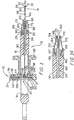
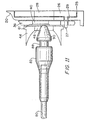
- a biopsy forceps instrument 10 generally includes a proximal handle assembly 12 and a distal jaw assembly 14.
- he proximal handle assembly 12 includes a shaft 16 having a central slot 18 and a spool 20 slidable on the shaft 16.
- the distal end of the shaft 16 is provided with a frustoconical shaft tip 22 having external double-helical threads 23 and a throughbore 24.
- the spool 20 is provided with a cross block 26 having a distal nub 27 and a central hole 28.
- the cross block 26 is seated in a channel 25 in the proximal portion of the spool 20 and passes through the central slot 18 of the shaft 16.
- the nub 27 of the cross block 26 locks into a hole 29 in the floor of the channel 25 and extends into a latch receptacle, described below.
- the central hole 28 is sized to permit the proximal end of a mating member, described below, to enter therein.
- the proximal end of the spool 20 is provided with a locking assembly 30 having a radially extending latch receptacle 32, a spring 34, and a push button latch 36.
- the latch receptacle 32 includes a cylindrical portion 32a and a channel portion 32b.
- the spring 34 is seated in the cylindrical portion 32a of the latch receptacle 32 and the latch 36 extends through the spring and into the channel portion 32b.
- the latch 36 includes a head 37, a distal side 39a, a proximal side 39b, a catch hole 40, and an interlock hole 42.
- the catch hole 40 is large enough to receive a mating member located on the pull wire, as described below, and preferably is provided with an approximately 600 chamfer around the catch hole 40 on the distal side 39a.
- the chamfer 41 facilitates movement of the mating member through the catch hole.
- the nub 27 on the cross block 26 extends through the interlock hole 42.
- the interlock hole 42 is larger than the nub 27, thereby permitting the latch 36 to move within the receptacle 32 relative to the nub 27.
- extension of the nub 27 through the interlock hole 42 prevents the latch 36 from being released from the receptacle 32.
- the spool 20 is also provided with a guide 38 which has laterally and distally extending portions 44, 46 which taper to a guide hole 48.
- the guide 38 is located in the spool 20 distal of the latch 36 and guides a mating member on the pull wire into engagement with the latch 36 as described hereinafter.
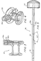
- the distal jaw assembly 14 includes a pair of sharp opposing jaws 50, 52 for grasping and tearing tissue for a biopsy sample.
- the jaws 50, 52 are preferably arranged about a clevis pin 54 which is mounted in a clevis 56 at the distal end of a relatively long flexible coil 58.
- the coil 58 is preferably covered in a substantially smooth wrap 60 which preferably has at its proximal end a plurality of barbs b-2.
- a threaded connecting sleeve 64 having a frustoconical proximal opening 66 and internal threads 68 in a double-helical configuration is provided at the proximal end of the coil 58.
- the threaded connecting sleeve 64 is preferably provided with several internal distal ridges 70 which engage the barbs 62 during manufacture, and is also provided with a plurality of longitudinal external gripping ridges 72 and depressions 74 to facilitate twisting the threaded connecting sleeve 64 onto the threaded frustoconical tip 22 of the shaft 16.
- a pull wire 80 is coupled at its distal end to the jaws 50, 52 and extends through the coil 58, the threaded connecting sleeve 64, the throughbore 24 of the shaft 16, and exits into the slot 18.
- a mating member 82 is provided at the proximal end of the pull wire 80.
- the mating member 82 generally has an elongate cylindrical distal portion 84, a frustoconical portion 85, a cylindrical central portion 86 having a relatively larger diameter, a cylindrical proximal grooved portion 88, and a conical proximal portion 90 preferably having a rounded apex 92.
- the elongate distal portion 84 has a bore 94 which receives the pull wire 80 so that the pull wire can be secured in the mating member by crimping.
- the distal portion 84 and the grooved portion 88 of the mating member nave substantially the same outer diameter.
- the conical portion 90 tapers towards the apex 92 at an angle ⁇ relative to a longitudinal axis of the mating member, wherein the angle ⁇ is preferably approximately between 15° - 25°. It is also preferable that the frustoconical portion 85 tapers towards the distal portion 84 at angle ⁇ relative to the longitudinal axis of the mating member. In order to facilitate insertion and removal of the mating member into the locking assembly, as described below, it is also preferable that the proximal rim 86a of the cylindrical portion 86 and the distal rim 90a of the conical portion be beveled.
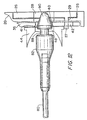
- the latch 36 in the spool and the mating member 82 on the pull wire 80 are arranged such that the pull wire 80 is coupled to the spool 20 in a single motion.
- the mating member end of the pull wire 80 is inserted through the guide hole 48 so that the mating member 82 engages the latch 36 at the catch hole 40 (Figure 11) and enters the catch hole and causes the latch to ride up the conical portion 90 of the mating member ( Figure 12).
- the grooved portion 88 of the mating member intersects the latch, such that the latch engages the grooved portion and secures the mating member ( Figure 13).
- the threaded connecting sleeve 46 at the proximal end of the coil 58 is easily connected to the shaft 16 by moving the threaded connecting sleeve onto the shaft tip 22 and applying a simple twisting motion.
- the frustoconical shapes of both the shaft tip 22 and the proximal opening 66 of the threaded connecting sleeve allow the threaded connecting sleeve to be substantially placed over the shaft tip prior to any twisting [notion, thereby enabling a rapid coupling.
- the combination of the frustoconical shapes and the double helical threads permit a coupling of the coil 58 to the shaft 16 using only one half a turn of the connecting sleeve 46 relative to the shaft.
- the distal assembly can easily be removed from proximal handle.
- the connecting sleeve is first rotated relative to the shaft to release the coil from the shaft.
- the pull wire 80 is then uncoupled from the spool 20 by depressing the latch 36 until the latch releases the grooved portion 88 of the mating member 82.
- the mating member can then be pulled through the catch hole 40 and the guide hole 48 to release the pull wire from the spool.
- the proximal handle can then be reused with another distal assembly.
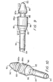
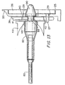
- FIG 14 a second embodiment of a biopsy forceps instrument, substantially similar to the biopsy forceps instrument of the first embodiment (with like parts indicated by numbers incremented by 100), is shown.
- a shaft 116 is provided having a frustoconical distal opening 195 and further having internal double-helical threads 196 and a throughbore 124.
- a threaded connecting sleeve 164 is provided at the proximal end of a shrink-wrap 160 covered coil 158.
- the threaded connecting sleeve 164 has a frustoconical proximal end 197 and external threads 198 in a double-helical configuration.
- the threaded connecting sleeve 164 is preferably provided with several internal ridges 170 for engaging barbs 162 of the shrink-wrapped coil, and is also preferably provided with a plurality of longitudinal gripping ridges 172 and depressions to facilitate gripping by the practitioner.
- the threaded connecting sleeve 164 can be connected to the shaft 116 by inserting the connector into the distal opening 195 of the shaft and by applying a simple twisting motion, such that the threaded connecting sleeve is rotated one half turn relative to the shaft.
- a pull wire 180 extends through the coil 158, the threaded connecting sleeve 164, the throughbore 124, and exits into the slot of the shaft where a mating member at the proximal end of the pull wire is engaged by a locking assembly provided in a spool on the shaft.
- crimping has been disclosed for coupling the pull wire to the mating member, it will be appreciated that soldering, welding, or gluing may also be used.
- guide has been shown to have laterally and distally extending guide portions, it will be appreciated that the guide may also take the form of a rounded funnel.
- latch has been shown to be coupled to the cross block at the nub, it will be understood that other latch to cross block couplings can be similarly used.
- the end effectors have been shown to be forceps jaws, it will be appreciated that other end effectors may also be used, e.g., grippers, cutters, dissectors, and scissors.
Description
A seen best in Figure 4, the
The proximal handle can then be reused with another distal assembly.
The threaded connecting
Claims (11)
- An endoscopic biopsy forceps instrument (10), comprising a tubular member (58) having a proximal end and a distal end, said proximal end having a threaded connecting member; a control member (80) extending through said tubular member (58); a shaft member (16) having a proximal end and a distal end; a sliding member (20) slidably mounted on said shaft member (16), said sliding member (20) provided with means (30) for detachably coupling to said control member (80); and an end effector (14) coupled to said distal ends of said control member (80) and tubular member (58) such that movement of said sliding member (20) relative to said shaft member (16) moves said end effector (14) from an open position to a closed position, characterized in that: said threaded connecting member (64) of the proximal end of said tubular member (58) includes one of a male and a female frustoconical portion having two parallel helical threads; and said distal end of said shaft member (16) includes the other of a male and a female frustoconical portion having two parallel helical threads, wherein threading said threaded connecting member (64) to said distal end of said shaft member (16) couples said tubular member (58) to said shaft member (16).
- A biopsy forceps instrument (10) according to claim 1, wherein:said threaded connecting member (64) has a distal end having at least one internal ridge (70), and said tubular member (58) has at least one barb (62) for interlocking with said internal ridge (70) to secure said threaded connecting member (64) to said tubular member (58).
- A biopsy forceps instrument (10) according to claim 2, wherein:said threaded connecting member (64) has at least one of a plurality of external ridges (72) and external grooves (74).
- A biopsy forceps instrument (10) according to claim 1, wherein:said means (30) for detachably coupling said control member (80) to said sliding member (20) includes a mating member (82) provided at said proximal end of said control member (80) and a locking means (30) provided in said sliding member (20).
- A biopsy forceps instrument (10) according to claim 4, wherein:unthreading said threaded connecting member (64) from said distal end of said shaft member (16) uncouples said tubular member (58) from said shaft member (16), and said locking means (30) is spring biased and movement of said locking means (30) against said bias uncouples said mating member (82) from said locking means (30).
- A biopsy forceps instrument (10) according to claim 5, wherein:said mating member (82) has an elongate distal portion (84), a substantially cylindrical central portion (86) having a relatively larger diameter, a substantially conical proximal portion (90), and a grooved portion (88) between said central portion (86) and said proximal portion (90), and said mating member (82) defines a longitudinal axis.
- A biopsy forceps instrument (10) according to claim 6, wherein:said proximal conical portion (90) tapers at an angle of approximately 15° - 25° toward said longitudinal axis.
- A biopsy forceps instrument (10) according to claim 7, wherein:said proximal conical portion (90) has a rounded apex.
- A biopsy forceps instrument (10) according to claim 6, wherein:said mating member (82) is further provided with a frustoconical portion (85) between said distal portion (84) and said central portion (86).
- A biopsy forceps instrument (10) according to claim 9, wherein:said frustoconical portion (85) tapers toward said distal portion at an angle approximately 15° - 25° relative to said longitudinal axis.
- A biopsy forceps instrument (10) according to claim 4, wherein:wherein said catch hole (40) and said guide hole (48) partially overlap.said locking means (30) includesi) a latch receptacle (32) in said sliding member (20),ii) a latch (36) seated in said latch receptacle (32) and defining a catch hole (40) adapted to receive said mating member (82),iii) a spring (34) seated in said latch receptacle (32) and biasing said latch (36) radially outward, andiv) a guide hole (48) for guiding said mating member generally toward said catch hole (40),
Applications Claiming Priority (3)
| Application Number | Priority Date | Filing Date | Title |
|---|---|---|---|
| US779034 | 1997-01-06 | ||
| US08/779,034 US5964717A (en) | 1997-01-06 | 1997-01-06 | Biopsy forceps having detachable handle and distal jaws |
| PCT/US1998/000080 WO1998030149A1 (en) | 1997-01-06 | 1998-01-06 | Biopsy forceps having detachable handle and distal jaws |
Publications (2)
| Publication Number | Publication Date |
|---|---|
| EP0998223A1 EP0998223A1 (en) | 2000-05-10 |
| EP0998223B1 true EP0998223B1 (en) | 2005-06-29 |
Family
ID=25115112
Family Applications (1)
| Application Number | Title | Priority Date | Filing Date |
|---|---|---|---|
| EP98901166A Expired - Lifetime EP0998223B1 (en) | 1997-01-06 | 1998-01-06 | Biopsy forceps having detachable handle and distal jaws |
Country Status (6)
| Country | Link |
|---|---|
| US (2) | US5964717A (en) |
| EP (1) | EP0998223B1 (en) |
| JP (1) | JP4094677B2 (en) |
| CA (1) | CA2274868C (en) |
| DE (1) | DE69830727T2 (en) |
| WO (1) | WO1998030149A1 (en) |
Families Citing this family (54)
| Publication number | Priority date | Publication date | Assignee | Title |
|---|---|---|---|---|
| US8414598B2 (en) | 1998-02-24 | 2013-04-09 | Hansen Medical, Inc. | Flexible instrument |
| US7214230B2 (en) | 1998-02-24 | 2007-05-08 | Hansen Medical, Inc. | Flexible instrument |
| US6810281B2 (en) | 2000-12-21 | 2004-10-26 | Endovia Medical, Inc. | Medical mapping system |
| US7775972B2 (en) | 1998-02-24 | 2010-08-17 | Hansen Medical, Inc. | Flexible instrument |
| US7090683B2 (en) | 1998-02-24 | 2006-08-15 | Hansen Medical, Inc. | Flexible instrument |
| US7713190B2 (en) | 1998-02-24 | 2010-05-11 | Hansen Medical, Inc. | Flexible instrument |
| US6949106B2 (en) | 1998-02-24 | 2005-09-27 | Endovia Medical, Inc. | Surgical instrument |
| US6162216A (en) * | 1998-03-02 | 2000-12-19 | Guziak; Robert Andrew | Method for biopsy and ablation of tumor cells |
| EP1005836A1 (en) * | 1998-12-03 | 2000-06-07 | Nivarox-FAR S.A. | Surgical instrument having detachable handle and operating unit |
| US6537205B1 (en) | 1999-10-14 | 2003-03-25 | Scimed Life Systems, Inc. | Endoscopic instrument system having reduced backlash control wire action |
| US6743185B2 (en) * | 2000-09-26 | 2004-06-01 | Scimed Life Systems, Inc. | Handle assembly for surgical instrument and method of making the assembly |
| DE10064623C1 (en) | 2000-12-22 | 2002-08-22 | Winter & Ibe Olympus | Endoscopic surgery forceps |
| US7766894B2 (en) | 2001-02-15 | 2010-08-03 | Hansen Medical, Inc. | Coaxial catheter system |
| US7699835B2 (en) | 2001-02-15 | 2010-04-20 | Hansen Medical, Inc. | Robotically controlled surgical instruments |
| US20030135204A1 (en) * | 2001-02-15 | 2003-07-17 | Endo Via Medical, Inc. | Robotically controlled medical instrument with a flexible section |
| US8414505B1 (en) | 2001-02-15 | 2013-04-09 | Hansen Medical, Inc. | Catheter driver system |
| US20040176751A1 (en) | 2002-08-14 | 2004-09-09 | Endovia Medical, Inc. | Robotic medical instrument system |
| US20040167430A1 (en) * | 2003-02-20 | 2004-08-26 | Roshdieh Babak B. | Cutaneous biopsy device with handle and disposable tips |
| US7837631B2 (en) * | 2003-03-14 | 2010-11-23 | Boston Scientific Scimed Inc. | Biopsy forceps with removable jaw segments |
| WO2005063127A1 (en) * | 2003-12-23 | 2005-07-14 | Cook Urological Incorporated | Back loading endoscopic instruments |
| US8444657B2 (en) * | 2004-05-07 | 2013-05-21 | Usgi Medical, Inc. | Apparatus and methods for rapid deployment of tissue anchors |
| US7850650B2 (en) | 2005-07-11 | 2010-12-14 | Covidien Ag | Needle safety shield with reset |
| US7905857B2 (en) | 2005-07-11 | 2011-03-15 | Covidien Ag | Needle assembly including obturator with safety reset |
| US7828773B2 (en) | 2005-07-11 | 2010-11-09 | Covidien Ag | Safety reset key and needle assembly |
| DE602006008740D1 (en) * | 2005-01-20 | 2009-10-08 | Wilson Cook Medical Inc | BIOPSY FORCEPS |
| US20060276747A1 (en) | 2005-06-06 | 2006-12-07 | Sherwood Services Ag | Needle assembly with removable depth stop |
| US7976553B2 (en) * | 2005-06-13 | 2011-07-12 | Ethicon Endo-Surgery, Inc. | Surgical suturing apparatus with detachable handle |
| US7731692B2 (en) | 2005-07-11 | 2010-06-08 | Covidien Ag | Device for shielding a sharp tip of a cannula and method of using the same |
| US7654735B2 (en) | 2005-11-03 | 2010-02-02 | Covidien Ag | Electronic thermometer |
| US7918783B2 (en) | 2006-03-22 | 2011-04-05 | Boston Scientific Scimed, Inc. | Endoscope working channel with multiple functionality |
| US8313500B2 (en) | 2006-04-14 | 2012-11-20 | Ethicon Endo-Surgery, Inc. | Endoscopic device |
| US7998167B2 (en) | 2006-04-14 | 2011-08-16 | Ethicon Endo-Surgery, Inc. | End effector and method of manufacture |
| US7857827B2 (en) | 2006-04-14 | 2010-12-28 | Ethicon Endo-Surgery, Inc. | Endoscopic device |
| ATE545374T1 (en) * | 2006-06-30 | 2012-03-15 | Bovie Medical Corp | SURGICAL INSTRUMENT WITH REMOVABLE TOOL ARRANGEMENT |
| US20080021278A1 (en) * | 2006-07-24 | 2008-01-24 | Leonard Robert F | Surgical device with removable end effector |
| WO2008067281A1 (en) * | 2006-11-30 | 2008-06-05 | Vance Products Incorporated D/B/A Cook Urological Incorporated | Removable handle for medical device |
| BRPI0807770A2 (en) * | 2007-02-19 | 2014-06-24 | Multi Biopsy Sampling Co Aps | Biopsy Forceps for one or more samples. |
| US8357104B2 (en) | 2007-11-01 | 2013-01-22 | Coviden Lp | Active stylet safety shield |
| DE102009022379A1 (en) | 2009-05-22 | 2010-11-25 | Epflex Feinwerktechnik Gmbh | Interchangeable handle system, especially for medical instruments |
| US8956341B2 (en) * | 2010-06-10 | 2015-02-17 | Carefusion 2200, Inc. | Surgical device with reusable handle |
| US8840630B2 (en) | 2011-06-15 | 2014-09-23 | Cook Medical Technologies Llc | Button release handle |
| EP2753250B1 (en) * | 2011-09-10 | 2019-03-20 | Cook Medical Technologies LLC | Control handles for medical devices |
| JP6076491B2 (en) * | 2013-02-20 | 2017-02-08 | オリンパス株式会社 | Medical manipulator |
| US9987036B2 (en) | 2014-10-03 | 2018-06-05 | Covidien Lp | System and method for powering an ultrasonic surgical device |
| US10194892B2 (en) * | 2014-10-15 | 2019-02-05 | Karl Storz Endovision, Inc. | Detachable articulating endoscopic tool cartridge |
| US9700445B2 (en) | 2014-11-04 | 2017-07-11 | Abbott Cardiovascular Systems, Inc. | One-way actuator knob |
| US10376673B2 (en) | 2015-06-19 | 2019-08-13 | Evalve, Inc. | Catheter guiding system and methods |
| US10238494B2 (en) | 2015-06-29 | 2019-03-26 | Evalve, Inc. | Self-aligning radiopaque ring |
| US10413408B2 (en) | 2015-08-06 | 2019-09-17 | Evalve, Inc. | Delivery catheter systems, methods, and devices |
| US10238495B2 (en) | 2015-10-09 | 2019-03-26 | Evalve, Inc. | Delivery catheter handle and methods of use |
| USD809139S1 (en) | 2015-10-09 | 2018-01-30 | Evalve, Inc. | Handle for a medical device |
| US10252035B2 (en) | 2015-12-07 | 2019-04-09 | Cook Medical Techonologies Llc | Rotatable control handles for medical devices and methods of using rotatable control handles |
| CN110037751B (en) * | 2019-04-25 | 2022-05-27 | 江苏华创高新医疗科技有限公司 | Sampling tool for tumor slices |
| CN113066768B (en) * | 2021-03-19 | 2022-06-10 | 深圳市嘉兴南电科技有限公司 | Fill diode for electric pile with good clamping capacity |
Family Cites Families (18)
| Publication number | Priority date | Publication date | Assignee | Title |
|---|---|---|---|---|
| US4763668A (en) * | 1985-10-28 | 1988-08-16 | Mill Rose Laboratories | Partible forceps instrument for endoscopy |
| DE3632786A1 (en) * | 1986-09-26 | 1988-03-31 | Wolfgang Griesat | Instrument for surgical interventions in body cavities |
| US4971067A (en) * | 1988-05-05 | 1990-11-20 | Lee Bolduc | Biopsy instrument with a disposable cutting blade |
| US4944741A (en) * | 1988-12-09 | 1990-07-31 | Hasson Harrith M | Laproscopic instrument with pivotable support arm |
| US5454378A (en) * | 1993-02-11 | 1995-10-03 | Symbiosis Corporation | Biopsy forceps having a detachable proximal handle and distal jaws |
| US5507297A (en) * | 1991-04-04 | 1996-04-16 | Symbiosis Corporation | Endoscopic instruments having detachable proximal handle and distal portions |
| US5304024A (en) * | 1991-03-18 | 1994-04-19 | Adolf Wurth Gmbh & Co. Kg | Screw, method and rolling die for the production thereof |
| US5391166A (en) * | 1991-06-07 | 1995-02-21 | Hemostatic Surgery Corporation | Bi-polar electrosurgical endoscopic instruments having a detachable working end |
| DE69230837T2 (en) * | 1991-08-21 | 2000-11-02 | Smith & Nephew Inc | Fluid treatment system |
| US5368606A (en) * | 1992-07-02 | 1994-11-29 | Marlow Surgical Technologies, Inc. | Endoscopic instrument system |
| US5308358A (en) * | 1992-08-25 | 1994-05-03 | Bond Albert L | Rigid-shaft surgical instruments that can be disassembled for improved cleaning |
| DE4323584A1 (en) * | 1993-07-14 | 1995-01-19 | Delma Elektro Med App | Detachable medical instrument |
| US5507774A (en) * | 1993-07-19 | 1996-04-16 | Wright Medical Technology, Inc. | Surgical instrument capable of disassembly |
| DE4332497C2 (en) * | 1993-09-24 | 1997-04-24 | Stefan Koscher | Surgical instrument |
| DE4341736A1 (en) * | 1993-12-08 | 1995-06-14 | Aesculap Ag | Surgical tubular shaft instrument |
| US5385561A (en) * | 1994-01-18 | 1995-01-31 | Bard International, Inc. | Apparatus and method for injecting a viscous material into the tissue of a patient |
| DE9418094U1 (en) * | 1994-11-15 | 1995-01-12 | Tontarra Medizintechnik Gmbh | Surgical tubular shaft instrument |
| US5603723A (en) * | 1995-01-11 | 1997-02-18 | United States Surgical Corporation | Surgical instrument configured to be disassembled for cleaning |
-
1997
- 1997-01-06 US US08/779,034 patent/US5964717A/en not_active Expired - Lifetime
- 1997-09-16 US US08/931,753 patent/US6007560A/en not_active Expired - Lifetime
-
1998
- 1998-01-06 CA CA002274868A patent/CA2274868C/en not_active Expired - Fee Related
- 1998-01-06 WO PCT/US1998/000080 patent/WO1998030149A1/en active IP Right Grant
- 1998-01-06 DE DE69830727T patent/DE69830727T2/en not_active Expired - Fee Related
- 1998-01-06 JP JP53099398A patent/JP4094677B2/en not_active Expired - Fee Related
- 1998-01-06 EP EP98901166A patent/EP0998223B1/en not_active Expired - Lifetime
Also Published As
| Publication number | Publication date |
|---|---|
| DE69830727D1 (en) | 2005-08-04 |
| CA2274868C (en) | 2006-07-11 |
| WO1998030149A1 (en) | 1998-07-16 |
| EP0998223A1 (en) | 2000-05-10 |
| US5964717A (en) | 1999-10-12 |
| JP4094677B2 (en) | 2008-06-04 |
| CA2274868A1 (en) | 1998-07-16 |
| US6007560A (en) | 1999-12-28 |
| DE69830727T2 (en) | 2005-12-01 |
| JP2001508339A (en) | 2001-06-26 |
Similar Documents
| Publication | Publication Date | Title |
|---|---|---|
| EP0998223B1 (en) | Biopsy forceps having detachable handle and distal jaws | |
| US5454378A (en) | Biopsy forceps having a detachable proximal handle and distal jaws | |
| US5782748A (en) | Endoscopic surgical instruments having detachable proximal and distal portions | |
| US5507297A (en) | Endoscopic instruments having detachable proximal handle and distal portions | |
| US6595984B1 (en) | Laparoscopic instrument with a detachable tip | |
| EP0817593B1 (en) | Endoscopic multiple sample bioptome with enhanced biting action | |
| US5810879A (en) | Laparoscopic instrument | |
| US5545170A (en) | Surgical instrument | |
| US7566331B2 (en) | Reconfigurable surgical apparatus | |
| US6074408A (en) | Modular medical instrument and method of using same | |
| AU669759B2 (en) | Surgical instrument | |
| US20200037858A1 (en) | Fairing for free scar instrument and method | |
| US5895361A (en) | Esophageal biopsy jaw assembly and endoscopic instrument incorporating the same | |
| CA2710251A1 (en) | Surgical instrument | |
| JP2020025857A (en) | Rotation knob assemblies and surgical instruments including the same | |
| CA2104345A1 (en) | Surgical clamp apparatus |
Legal Events
| Date | Code | Title | Description |
|---|---|---|---|
| PUAI | Public reference made under article 153(3) epc to a published international application that has entered the european phase |
Free format text: ORIGINAL CODE: 0009012 |
|
| 17P | Request for examination filed |
Effective date: 19990726 |
|
| AK | Designated contracting states |
Kind code of ref document: A1 Designated state(s): DE FR GB IE NL |
|
| 17Q | First examination report despatched |
Effective date: 20040227 |
|
| GRAP | Despatch of communication of intention to grant a patent |
Free format text: ORIGINAL CODE: EPIDOSNIGR1 |
|
| GRAS | Grant fee paid |
Free format text: ORIGINAL CODE: EPIDOSNIGR3 |
|
| GRAA | (expected) grant |
Free format text: ORIGINAL CODE: 0009210 |
|
| AK | Designated contracting states |
Kind code of ref document: B1 Designated state(s): DE FR GB IE NL |
|
| REG | Reference to a national code |
Ref country code: GB Ref legal event code: FG4D |
|
| REF | Corresponds to: |
Ref document number: 69830727 Country of ref document: DE Date of ref document: 20050804 Kind code of ref document: P |
|
| REG | Reference to a national code |
Ref country code: IE Ref legal event code: FG4D |
|
| ET | Fr: translation filed | ||
| PLBE | No opposition filed within time limit |
Free format text: ORIGINAL CODE: 0009261 |
|
| STAA | Information on the status of an ep patent application or granted ep patent |
Free format text: STATUS: NO OPPOSITION FILED WITHIN TIME LIMIT |
|
| 26N | No opposition filed |
Effective date: 20060330 |
|
| PGFP | Annual fee paid to national office [announced via postgrant information from national office to epo] |
Ref country code: GB Payment date: 20061213 Year of fee payment: 10 |
|
| PGFP | Annual fee paid to national office [announced via postgrant information from national office to epo] |
Ref country code: NL Payment date: 20061222 Year of fee payment: 10 |
|
| PGFP | Annual fee paid to national office [announced via postgrant information from national office to epo] |
Ref country code: IE Payment date: 20070111 Year of fee payment: 10 |
|
| PGFP | Annual fee paid to national office [announced via postgrant information from national office to epo] |
Ref country code: DE Payment date: 20070131 Year of fee payment: 10 |
|
| PGFP | Annual fee paid to national office [announced via postgrant information from national office to epo] |
Ref country code: FR Payment date: 20070103 Year of fee payment: 10 |
|
| GBPC | Gb: european patent ceased through non-payment of renewal fee |
Effective date: 20080106 |
|
| NLV4 | Nl: lapsed or anulled due to non-payment of the annual fee |
Effective date: 20080801 |
|
| REG | Reference to a national code |
Ref country code: IE Ref legal event code: MM4A |
|
| PG25 | Lapsed in a contracting state [announced via postgrant information from national office to epo] |
Ref country code: NL Free format text: LAPSE BECAUSE OF NON-PAYMENT OF DUE FEES Effective date: 20080801 Ref country code: DE Free format text: LAPSE BECAUSE OF NON-PAYMENT OF DUE FEES Effective date: 20080801 |
|
| REG | Reference to a national code |
Ref country code: FR Ref legal event code: ST Effective date: 20081029 |
|
| PG25 | Lapsed in a contracting state [announced via postgrant information from national office to epo] |
Ref country code: GB Free format text: LAPSE BECAUSE OF NON-PAYMENT OF DUE FEES Effective date: 20080106 |
|
| PG25 | Lapsed in a contracting state [announced via postgrant information from national office to epo] |
Ref country code: IE Free format text: LAPSE BECAUSE OF NON-PAYMENT OF DUE FEES Effective date: 20080107 |
|
| PG25 | Lapsed in a contracting state [announced via postgrant information from national office to epo] |
Ref country code: FR Free format text: LAPSE BECAUSE OF NON-PAYMENT OF DUE FEES Effective date: 20080131 |