EP0999025A2 - Method for manufacturing contoured and laminated materials - Google Patents
Method for manufacturing contoured and laminated materials Download PDFInfo
- Publication number
- EP0999025A2 EP0999025A2 EP98610050A EP98610050A EP0999025A2 EP 0999025 A2 EP0999025 A2 EP 0999025A2 EP 98610050 A EP98610050 A EP 98610050A EP 98610050 A EP98610050 A EP 98610050A EP 0999025 A2 EP0999025 A2 EP 0999025A2
- Authority
- EP
- European Patent Office
- Prior art keywords
- layer
- station
- intermediate product
- backing
- film
- Prior art date
- Legal status (The legal status is an assumption and is not a legal conclusion. Google has not performed a legal analysis and makes no representation as to the accuracy of the status listed.)
- Granted
Links
Images


Classifications
-
- B—PERFORMING OPERATIONS; TRANSPORTING
- B29—WORKING OF PLASTICS; WORKING OF SUBSTANCES IN A PLASTIC STATE IN GENERAL
- B29C—SHAPING OR JOINING OF PLASTICS; SHAPING OF MATERIAL IN A PLASTIC STATE, NOT OTHERWISE PROVIDED FOR; AFTER-TREATMENT OF THE SHAPED PRODUCTS, e.g. REPAIRING
- B29C43/00—Compression moulding, i.e. applying external pressure to flow the moulding material; Apparatus therefor
- B29C43/22—Compression moulding, i.e. applying external pressure to flow the moulding material; Apparatus therefor of articles of indefinite length
-
- A—HUMAN NECESSITIES
- A61—MEDICAL OR VETERINARY SCIENCE; HYGIENE
- A61F—FILTERS IMPLANTABLE INTO BLOOD VESSELS; PROSTHESES; DEVICES PROVIDING PATENCY TO, OR PREVENTING COLLAPSING OF, TUBULAR STRUCTURES OF THE BODY, e.g. STENTS; ORTHOPAEDIC, NURSING OR CONTRACEPTIVE DEVICES; FOMENTATION; TREATMENT OR PROTECTION OF EYES OR EARS; BANDAGES, DRESSINGS OR ABSORBENT PADS; FIRST-AID KITS
- A61F13/00—Bandages or dressings; Absorbent pads
- A61F13/00987—Apparatus or processes for manufacturing non-adhesive dressings or bandages
-
- B—PERFORMING OPERATIONS; TRANSPORTING
- B29—WORKING OF PLASTICS; WORKING OF SUBSTANCES IN A PLASTIC STATE IN GENERAL
- B29C—SHAPING OR JOINING OF PLASTICS; SHAPING OF MATERIAL IN A PLASTIC STATE, NOT OTHERWISE PROVIDED FOR; AFTER-TREATMENT OF THE SHAPED PRODUCTS, e.g. REPAIRING
- B29C43/00—Compression moulding, i.e. applying external pressure to flow the moulding material; Apparatus therefor
- B29C43/02—Compression moulding, i.e. applying external pressure to flow the moulding material; Apparatus therefor of articles of definite length, i.e. discrete articles
- B29C43/20—Making multilayered or multicoloured articles
- B29C43/203—Making multilayered articles
- B29C43/206—Making multilayered articles by pressing the material between two preformed layers, e.g. deformable layers
-
- Y—GENERAL TAGGING OF NEW TECHNOLOGICAL DEVELOPMENTS; GENERAL TAGGING OF CROSS-SECTIONAL TECHNOLOGIES SPANNING OVER SEVERAL SECTIONS OF THE IPC; TECHNICAL SUBJECTS COVERED BY FORMER USPC CROSS-REFERENCE ART COLLECTIONS [XRACs] AND DIGESTS
- Y10—TECHNICAL SUBJECTS COVERED BY FORMER USPC
- Y10T—TECHNICAL SUBJECTS COVERED BY FORMER US CLASSIFICATION
- Y10T156/00—Adhesive bonding and miscellaneous chemical manufacture
- Y10T156/10—Methods of surface bonding and/or assembly therefor
- Y10T156/1002—Methods of surface bonding and/or assembly therefor with permanent bending or reshaping or surface deformation of self sustaining lamina
- Y10T156/1039—Surface deformation only of sandwich or lamina [e.g., embossed panels]
- Y10T156/1041—Subsequent to lamination
-
- Y—GENERAL TAGGING OF NEW TECHNOLOGICAL DEVELOPMENTS; GENERAL TAGGING OF CROSS-SECTIONAL TECHNOLOGIES SPANNING OVER SEVERAL SECTIONS OF THE IPC; TECHNICAL SUBJECTS COVERED BY FORMER USPC CROSS-REFERENCE ART COLLECTIONS [XRACs] AND DIGESTS
- Y10—TECHNICAL SUBJECTS COVERED BY FORMER USPC
- Y10T—TECHNICAL SUBJECTS COVERED BY FORMER US CLASSIFICATION
- Y10T156/00—Adhesive bonding and miscellaneous chemical manufacture
- Y10T156/10—Methods of surface bonding and/or assembly therefor
- Y10T156/1052—Methods of surface bonding and/or assembly therefor with cutting, punching, tearing or severing
- Y10T156/1084—Methods of surface bonding and/or assembly therefor with cutting, punching, tearing or severing of continuous or running length bonded web
Definitions
- the present invention relates to the field of continuous line manufacturing, and more particularly to the field of manufacturing laminated and contoured components on a continuous manufacturing line.
- Laminated devices or components are available in many forms for a variety of purposes. Wound dressings, surgical dressings, medical adhesives and other like medical devices are often laminated to provide a skin-contacting layer, a backing layer and a release sheet layer.
- the skin-contacting layer is used as a dressing or adhesive function and may be comprised of a variety of materials depending on the purpose of the device. Exemplary materials include hydrocolloid adhesives, hydrogels, non-wovens, foams, etc. It may be advantageous to contour, or shape the skin-contacting layer to provide conformability.
- the backing layer is often attached to the skin-contacting layer to provide a protective covering.
- the release sheet layer is attached to the skin-contacting layer on the side opposite the backing layer with a release coating to permit removal of the release sheet layer during application.
- Each layer may be composed of other layers, or sub-layers depending on the application for which the device is intended.
- the skin-contacting layer may have an adhesive layer attached to a moisture-absorbing or moisture-removing layer, such as a foam or non-woven.
- fixation wafers for prostheses e.g breast prostheses
- ostomy wafers Other devices that may be laminated and contoured include inner-soles for shoes.
- shock-absorbing materials such as foam, soft rubber or other suitable materials. These materials may be covered by protective plastic films such as, polypropylene, polyethylene, polyurethane, etc.
- Laminated devices may be difficult to manufacture. Because such devices may be high-volume devices, the method used for their manufacture should be as efficient as possible. Incremental costs may be magnified substantially as the volume of devices increases. In the case of medical devices, the need to manufacture in clean room or other specially controlled environment further complicates the process. Clean rooms may be expensive to maintain, particularly for high-grade medical devices that must be manufactured in clean rooms.
- devices that are contoured may be more difficult to manufacture.
- Such contouring may involve shaping the materials comprising the devices at elevated temperature.
- the shaping may be performed using methods that stress the materials to a point at or near the ability of the materials to maintain a useful structure.
- wound dressings may have backing layers made of polyethylene films that provide a flexible and impermeable covering for the skin-contacting layer. These materials may not have the strength to permit shaping at elevated temperatures.
- Jensen '821 One method for manufacturing wound dressings having skin-contacting layers made of hydrocolloid-adhesive and gel-like adhesive taught by Jensen in U.S. Patent No. 5,133,821 (hereinafter Jensen '821) uses an in-line, substantially continuous process that minimizes the time and energy needed to make the dressings.
- Jensen '821 teaches a method in which the adhesive layer is covered by a protective layer on one surface and a release sheet layer on the opposing surface. The layers are contoured at a contouring station to produce a first laminate.
- the first laminate is carried through a delaminating station, which removes the protective layer to expose the surface of the adhesive.
- the exposed surface is then covered by a carrier layer at a laminating station and cut into discrete wound dressings at a cutting station.
- the advantage of using the process in Jensen '821 is that the adhesive layer is protected by a protective layer during the contouring.
- the protective layer is made of paper or polyester that is coated with silicone for easy release during the removal of the layer.
- the backing layer is applied after the contouring of the adhesive layer such that the backing layer is not subject to the forces applied to the adhesive during contouring nor to the elevated temperatures that may be required to perform the contouring.
- the methods taught in Jensen '821 also include steps that add to the time required to manufacture the laminated and contoured devices. It would be further desirable to reduce the time to manufacture the laminated and contoured devices.
- the laminating station may have the effect of deforming the contour achieved by the contouring station when the carrier layer is pressed to the exposed adhesive. It would be desirable to eliminate the need to apply too much pressure to the contoured adhesive surface.
- Figure 1 shows an individual laminated and contoured device 24 that is representative of an end product that may be made by using methods according to the present inention.
- This device 5 has a thick portion 6 and a thin flange portion 7.
- the device 5 may be a wound dressing, a surgical dressing, a fixation wafer for protheses, an ostomy wafer, or any medical device that is laminated and contoured.
- the device 5 may also include non-medical devices such as shoe inner-soles.
- the shape of the device 5 in Figure 1 is rectangular, however, the device 5 may have any shape and contour.
- Figure 2 shows a fragmentary cross-sectional view of one example of the end product 24 shown in Figure 1.
- the end product 24 in Figure 2 includes a subject layer 8, a first outer layer 12, and a second outer layer 11.
- the subject layer 8 may perform the primary function of the device.
- the subject layer 8 may be a foam or other substance that provides the main cushioning of the inner-sole.
- the subject layer 8 may be a hydrocolloid-adhesive, a hydrogel, a polyurethane or other type of foam, a non-woven or any other suitable dressing material.
- the first outer layer 12 provides a protective covering for the subject layer 8.
- a first outer layer 12 made of a polyethylene film, a polyurethane film, a non-woven or other suitable film may be used as a protective cover for the subject layer 8.
- Other materials may be used for the first outer layer 12 depending on the function of the subject layer 8.
- the second outer layer 11 may be provided as a protective covering for the subject layer 8 on the side opposite the first outer layer 12.
- the second outer layer 11 may be a release sheet that may be removed during the application of the dressing.
- the second outer layer 11 is preferably made of a silicone release paper or other flexible material treated for easy removal from the subject layer 8.
- Other materials include polyester, polyurethane and polyethylene films.
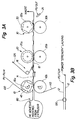
- the end product 24 shown in Figure 2 where the first outer layer 12 is a backing film 120 for a wound dressing, the subject layer 8 is a hydrocolloid-adhesive 80 and the second outer layer 110 is a release sheet film, may be manufactured using a substantially continuous in-line method.
- the method shown in Figure 3A includes steps of:
- a substantially continuous backing film 120 is fed from a supply roller (not shown).
- the continuous film is fed into a contouring roller 10a and the release sheet film 110 is fed from a supply roller (not shown) at a second contouring roller 10b opposing the first contouring roller 10a.
- the hydrocolloid adhesive material is provided as a continuous strip at the contouring laminating rollers 10a, 10b.
- the hydrocolloid adhesive material is preferably provided by extrusion such that the hydrocolloid adhesive material 80 is interposed between the backing layer film 120 and the release sheet film 110.
- the hydrocolloid adhesive material, or any other material selected for the subject layer 8 may also be ram-fed, pressed, injected or fed as a film.
- the attached layers are contoured by the co-operating rotational action of the contouring and laminating roller 10a and the second roller 10b.
- the contouring roller 10a has been relieved around its peripheral surface to provide shaped pockets 48.
- the pockets 48 are shaped according to the desired final contour of the end product 24.
- the backing film 120 includes a backing layer 120a and a support layer 120b.
- the support layer 120b protects the backing layer 120a during the contouring by the contouring roller 120a.
- the recess 48 in the roller 10a applies a force to the support layer 120b, the backing layer 120a and the adhesive layer 80 that combined with the malleability of the adhesive layer 80, stresses the backing film 120.
- the backing layer 120a is preferably made of a polyethylene film. By applying the backing film 120 with the support layer 120b, the backing film 120a is protected regardless of its thickness and material.
- the silicone release coating on the support layer 120b allows for easy later removal.
- One of ordinary skill in the art will appreciate that other backing films 120 may be used.
- the rotational action of the contouring roller 10a and the second roller 10b as the three layers are supplied between the rollers produces a laminated first intermediate product 14.
- a cross-sectional view of the intermediate product 14 is shown in Figure 4.
- the intermediate product 14 includes the support layer 120b and the backing layer 120a that comprise the backing film 120, the adhesive layer 80 and the release sheet film 110.
- the support layer 120b is removed at the delaminating station 16 to produce a second intermediate product 18.
- the second intemediate product 18 is carried through the driving rollers 20a and 20b at the driving station 20.
- the driving station 20 advantageously moves the continuous strip of first and second intermediate products to the cutting station 30, however, the driving station 20 is optional.
- the second intermediate product 18 includes the backing layer 120a, the adhesive layer 80 and the release sheet film 110. Another advantage of using the backing film 120 with the support layer 120b is that at the removal of the support layer 120b at the delaminating station 16 the adhesive layer 80 remains covered. The need for separate laminating station after the delaminating station 16 is precluded thereby providing a more efficient and less wasteful process.
- the driving cylinder 20a is preferably coated with rubber and driven to rotate to carry the second intermediate product 18 to the cutting station 30.
- a cutting roller 30a and the second cutting roller 30b are rotated at a selected speed to cut the second intermediate product 18 into individual wound dressings that make up the end product 24.
- the first cutting roller 30a comprises a cutting pattern shaped according to the shape selected for the end product 24.
- the end products 24 are delivered to a collection site or to a subsequent packaging operation.
- the rollers of the contouring and laminating station 10, the driving station 20 and the cutting station 30 are rotated in a timed and synchronized relationship to each other to provide the desired spacing and contours between the dressings.
- This timed relationship may be provided mechanically, electro-mechanically, electronically or by other suitable means.
- the individual stations should be individually adjustable with respect to the spacing between each pair of associated rollers to provide or compensate for the desired thickness of the wound dressing.
- the methods of manufacturing the end product 24 described above with reference to Figure 3A may also be used to manufacture other types of wound dressings, surgical dressings, and other medical devices.
- Other types of non-medical devices may also be manufactured, including shoe inner-soles.
- the adhesive layer 80 may be made of hydrogel, non-woven, foam (e.g. polyurethane foam), etc.
Abstract
Description
- The present invention relates to the field of continuous line manufacturing, and more particularly to the field of manufacturing laminated and contoured components on a continuous manufacturing line.
- Laminated devices or components are available in many forms for a variety of purposes. Wound dressings, surgical dressings, medical adhesives and other like medical devices are often laminated to provide a skin-contacting layer, a backing layer and a release sheet layer.
- The skin-contacting layer is used as a dressing or adhesive function and may be comprised of a variety of materials depending on the purpose of the device. Exemplary materials include hydrocolloid adhesives, hydrogels, non-wovens, foams, etc. It may be advantageous to contour, or shape the skin-contacting layer to provide conformability.
- The backing layer is often attached to the skin-contacting layer to provide a protective covering. The release sheet layer is attached to the skin-contacting layer on the side opposite the backing layer with a release coating to permit removal of the release sheet layer during application. Each layer may be composed of other layers, or sub-layers depending on the application for which the device is intended. For example, the skin-contacting layer may have an adhesive layer attached to a moisture-absorbing or moisture-removing layer, such as a foam or non-woven.
- Examples of wound dressings and methods for manufacturing such dressings are taught by Chen (U.S. Patent No. 3,339,546) and Samuelson (U.S. Patent No. 4,867,748, issued September 19, 1989).
- Other medical devices that may be laminated for purposes of application or packaging include fixation wafers for prostheses (e.g breast prostheses) and ostomy wafers. Other devices that may be laminated and contoured include inner-soles for shoes. Instead of a skin-contacting layer such devices may include shock-absorbing materials, such as foam, soft rubber or other suitable materials. These materials may be covered by protective plastic films such as, polypropylene, polyethylene, polyurethane, etc.
- Laminated devices may be difficult to manufacture. Because such devices may be high-volume devices, the method used for their manufacture should be as efficient as possible. Incremental costs may be magnified substantially as the volume of devices increases. In the case of medical devices, the need to manufacture in clean room or other specially controlled environment further complicates the process. Clean rooms may be expensive to maintain, particularly for high-grade medical devices that must be manufactured in clean rooms.
- In addition, devices that are contoured may be more difficult to manufacture. Such contouring may involve shaping the materials comprising the devices at elevated temperature. The shaping may be performed using methods that stress the materials to a point at or near the ability of the materials to maintain a useful structure. For example, wound dressings may have backing layers made of polyethylene films that provide a flexible and impermeable covering for the skin-contacting layer. These materials may not have the strength to permit shaping at elevated temperatures.
- One method for manufacturing wound dressings having skin-contacting layers made of hydrocolloid-adhesive and gel-like adhesive taught by Jensen in U.S. Patent No. 5,133,821 (hereinafter Jensen '821) uses an in-line, substantially continuous process that minimizes the time and energy needed to make the dressings. Jensen '821 teaches a method in which the adhesive layer is covered by a protective layer on one surface and a release sheet layer on the opposing surface. The layers are contoured at a contouring station to produce a first laminate. The first laminate is carried through a delaminating station, which removes the protective layer to expose the surface of the adhesive. The exposed surface is then covered by a carrier layer at a laminating station and cut into discrete wound dressings at a cutting station.
- The advantage of using the process in Jensen '821 is that the adhesive layer is protected by a protective layer during the contouring. The protective layer is made of paper or polyester that is coated with silicone for easy release during the removal of the layer. The backing layer is applied after the contouring of the adhesive layer such that the backing layer is not subject to the forces applied to the adhesive during contouring nor to the elevated temperatures that may be required to perform the contouring.
- One problem with the methods taught in Jensen '821 is that the adhesive layer is exposed during the process. Because the laminating station adds the carrier layer to the exposed surface of the adhesive, or the layer to be contoured, the likelihood of introducing air pockets between the adhesive and the carrier layer is increased. It would be desirable to maintain the adhesive surface covered during the process.
- The methods taught in Jensen '821 also include steps that add to the time required to manufacture the laminated and contoured devices. It would be further desirable to reduce the time to manufacture the laminated and contoured devices.
- In addition, the laminating station may have the effect of deforming the contour achieved by the contouring station when the carrier layer is pressed to the exposed adhesive. It would be desirable to eliminate the need to apply too much pressure to the contoured adhesive surface.
- The process in Jensen '821 yields substantial waste due to the removal of the protective layer prior to the addition of the backing layer. The cost of the waste is magnified when materials such as polyester are used. It would be desirable to reduce the cost of manufacturing laminated and contoured devices by eliminating the need to add and then remove a layer.
- It would be further desirable to reduce the time required to carry out the process of manufacturing the laminated and contoured devices.
- Presently preferred embodiments of the invention are described below in conjunction with the appended drawing figures, wherein like reference numerals refer to like elements in the various figures, and wherein:
- Figure 1 represents a perspective view of one type of a laminated and contoured device that may be made by using the method of the present invention.
- Figure 2 represents a fragmentary cross-sectional view of the device in Figure 1.
- Figure 3A shows a schematic diagram of one embodiment of the present invention.
- Figure 3B shows a cross section of a component used in the embodiment shown in Figure 3A.
- Figure 4 shows a fragmentary cross-sectional view of an intermediate product of the method shown in Figure 3A.
-
- Figure 1 shows an individual laminated and
contoured device 24 that is representative of an end product that may be made by using methods according to the present inention. Thisdevice 5 has athick portion 6 and athin flange portion 7. - The
device 5 may be a wound dressing, a surgical dressing, a fixation wafer for protheses, an ostomy wafer, or any medical device that is laminated and contoured. Thedevice 5 may also include non-medical devices such as shoe inner-soles. The shape of thedevice 5 in Figure 1 is rectangular, however, thedevice 5 may have any shape and contour. - Figure 2 shows a fragmentary cross-sectional view of one example of the
end product 24 shown in Figure 1. Theend product 24 in Figure 2 includes a subject layer 8, a firstouter layer 12, and a second outer layer 11. The subject layer 8 may perform the primary function of the device. For example, for an inner-sole, the subject layer 8 may be a foam or other substance that provides the main cushioning of the inner-sole. For a wound dressing, the subject layer 8 may be a hydrocolloid-adhesive, a hydrogel, a polyurethane or other type of foam, a non-woven or any other suitable dressing material. - Preferred embodiments for a process for manufacturing laminated and contoured devices are described below where the
end product 24 is a wound dressing having a hydrocolloid-adhesive as the subject layer 8. Those of ordinary skill in the art will appreciate that other laminated and contoured devices may be manufactured using embodiments of the present invention. - The first
outer layer 12 provides a protective covering for the subject layer 8. A firstouter layer 12 made of a polyethylene film, a polyurethane film, a non-woven or other suitable film may be used as a protective cover for the subject layer 8. Other materials may be used for the firstouter layer 12 depending on the function of the subject layer 8. - The second outer layer 11 may be provided as a protective covering for the subject layer 8 on the side opposite the first
outer layer 12. In a wound dressing, the second outer layer 11 may be a release sheet that may be removed during the application of the dressing. In a wound dressing, the second outer layer 11 is preferably made of a silicone release paper or other flexible material treated for easy removal from the subject layer 8. Other materials include polyester, polyurethane and polyethylene films. - Examples of the
end product 24 used as a wound dressing as shown in Figure 2 as well as of other types of products that may be manufactured using methods of the present invention may be found in U.S. Patent No. 5,133,821 to Jensen (incorporated herein by reference); U.S. Patent No. 5,591,447 to Jensen (incorporated herein by reference) and U.S. Patent No. 4,867,748 to Samuelson. - Referring to Figure 3A, the
end product 24 shown in Figure 2, where the firstouter layer 12 is abacking film 120 for a wound dressing, the subject layer 8 is a hydrocolloid-adhesive 80 and the secondouter layer 110 is a release sheet film, may be manufactured using a substantially continuous in-line method. The method shown in Figure 3A includes steps of: - 1. supplying the end product materials to a contouring and laminating station 10
to produce an
intermediate product 14; - 2. providing the intermediate product to a delaminating
station 16 to produce a secondintermediate product 18; - 3. feeding the second
intermediate product 18 to a drivingstation 20; and - 4. cutting out the
end products 24 using a cuttingstation 30. -
- At the contouring and laminating station 10, a substantially
continuous backing film 120 is fed from a supply roller (not shown). The continuous film is fed into acontouring roller 10a and therelease sheet film 110 is fed from a supply roller (not shown) at asecond contouring roller 10b opposing thefirst contouring roller 10a. The hydrocolloid adhesive material is provided as a continuous strip at the contouringlaminating rollers - The hydrocolloid adhesive material is preferably provided by extrusion such that the
hydrocolloid adhesive material 80 is interposed between thebacking layer film 120 and therelease sheet film 110. The hydrocolloid adhesive material, or any other material selected for the subject layer 8, may also be ram-fed, pressed, injected or fed as a film. - The attached layers (i.e. the
backing film 120, theadhesive layer 80 and the release sheet layer 110) are contoured by the co-operating rotational action of the contouring andlaminating roller 10a and thesecond roller 10b. The contouringroller 10a has been relieved around its peripheral surface to provide shapedpockets 48. Thepockets 48 are shaped according to the desired final contour of theend product 24. - A cross-sectional fragmentary view of the
backing film 120 is shown in Figure 3B. Thebacking film 120 includes a backing layer 120a and a support layer 120b. The support layer 120b protects the backing layer 120a during the contouring by the contouring roller 120a. As the laminate is contoured, therecess 48 in theroller 10a applies a force to the support layer 120b, the backing layer 120a and theadhesive layer 80 that combined with the malleability of theadhesive layer 80, stresses thebacking film 120. The backing layer 120a is preferably made of a polyethylene film. By applying thebacking film 120 with the support layer 120b, the backing film 120a is protected regardless of its thickness and material. The silicone release coating on the support layer 120b allows for easy later removal. One of ordinary skill in the art will appreciate thatother backing films 120 may be used. - Referring back to Figure 3A, the rotational action of the contouring
roller 10a and thesecond roller 10b as the three layers are supplied between the rollers produces a laminated firstintermediate product 14. A cross-sectional view of theintermediate product 14 is shown in Figure 4. As shown in Figure 4, theintermediate product 14 includes the support layer 120b and the backing layer 120a that comprise thebacking film 120, theadhesive layer 80 and therelease sheet film 110. - Referring back to Figure 3A, the support layer 120b is removed at the delaminating
station 16 to produce a secondintermediate product 18. Thesecond intemediate product 18 is carried through the drivingrollers station 20. The drivingstation 20 advantageously moves the continuous strip of first and second intermediate products to the cuttingstation 30, however, the drivingstation 20 is optional. The secondintermediate product 18 includes the backing layer 120a, theadhesive layer 80 and therelease sheet film 110. Another advantage of using thebacking film 120 with the support layer 120b is that at the removal of the support layer 120b at the delaminatingstation 16 theadhesive layer 80 remains covered. The need for separate laminating station after the delaminatingstation 16 is precluded thereby providing a more efficient and less wasteful process. - The driving
cylinder 20a is preferably coated with rubber and driven to rotate to carry the secondintermediate product 18 to the cuttingstation 30. At the cuttingstation 30, a cuttingroller 30a and thesecond cutting roller 30b are rotated at a selected speed to cut the secondintermediate product 18 into individual wound dressings that make up theend product 24. Thefirst cutting roller 30a comprises a cutting pattern shaped according to the shape selected for theend product 24. Theend products 24 are delivered to a collection site or to a subsequent packaging operation. - The rollers of the contouring and laminating station 10, the driving
station 20 and the cuttingstation 30 are rotated in a timed and synchronized relationship to each other to provide the desired spacing and contours between the dressings. This timed relationship may be provided mechanically, electro-mechanically, electronically or by other suitable means. The individual stations should be individually adjustable with respect to the spacing between each pair of associated rollers to provide or compensate for the desired thickness of the wound dressing. - While examples of preferred embodiments of processes for manufacturing the
end product 24 wound dressing have been described, it is to be understood by one of ordinary skill in the art that alternative embodiments falling within a scope of the claims are possible. For example, it may be possible to eliminate the drivingstation 20 leaving only the contouring and laminating station 10 and the cuttingstation 30. In addition, other stations may be added to provide additional features and advantages. - The methods of manufacturing the
end product 24 described above with reference to Figure 3A may also be used to manufacture other types of wound dressings, surgical dressings, and other medical devices. Other types of non-medical devices may also be manufactured, including shoe inner-soles. One of ordinary skill in the art will appreciate that different materials may be used for thebacking film 120, theadhesive layer 80 and the secondouter layer 110 to manufacture products having selected features. For example, theadhesive layer 80 may be made of hydrogel, non-woven, foam (e.g. polyurethane foam), etc. - Persons of ordinary skill in the art will appreciate that variations may be made without departure from the scope and spirit of the invention. This true scope and spirit is defined by the appended claims, interpreted in light of the foregoing.
Claims (7)
- A method for manufacturing wound dressings comprising the steps of: providing a continuous supply of a first outer layer having a support layer and a backing layer, the support layer being of a material sufficient to protect the backing layer and having a release coating; providing a continuous supply of a second outer layer having a second release coating; providing a subject layer of a material having predetermined malleability and a first surface and a second surface; contouring and attaching the first outer layer to the first surface of the subject layer and attaching the second outer layer to the second surface of the subject layer, and to form a first intermediate product at a contouring and laminating station; removing the support layer from the backing film on the first intermediate product at a delaminating station to form a second intermediate product comprising the subject layer interposed between the backing layer and the second outer layer; and cutting the second intermediate product into discrete end products by carrying the second intermediate product through a cutting station in a predetermined registered and timed relationship.
- A method as claimed in Claim 1 further comprising the step of driving the second intermediate product to the cutting station using a driving station.
- A method as claimed in Claim 1 wherein the step of providing the first outer layer includes the step of attaching the support layer to the backing film.
- A method as claimed in Claim 1 wherein the backing film is made of a material selected from the group consisting of a polyethylene film, a polyurethane film, and a non-woven.
- A method as claimed in Claim 1 wherein the step of providing the first outer layer includes the step of attaching the support layer comprising a silicon release coated paper film to the backing film.
- A method as claimed in Claim 1 wherein the step of providing the first outer layer includes the step of attaching the support layer comprising a silicon release coated rubber film to the backing film.
- A method as claimed in Claim 1 wherein the subject layer is made of a material selected from the group consisting of a hydrocolloid adhesive, a hydrogel, a non-woven, a polyurethane foam, an adhesive foam and an adhesive coated foam.
Priority Applications (1)
| Application Number | Priority Date | Filing Date | Title |
|---|---|---|---|
| DE69830908.1T DE69830908T3 (en) | 1998-11-02 | 1998-12-22 | Method for producing profiled and laminated materials |
Applications Claiming Priority (2)
| Application Number | Priority Date | Filing Date | Title |
|---|---|---|---|
| US184811 | 1998-11-02 | ||
| US09/184,811 US6309500B1 (en) | 1998-11-02 | 1998-11-02 | Method for manufacturing contoured and laminated materials |
Publications (4)
| Publication Number | Publication Date |
|---|---|
| EP0999025A2 true EP0999025A2 (en) | 2000-05-10 |
| EP0999025A3 EP0999025A3 (en) | 2002-09-04 |
| EP0999025B1 EP0999025B1 (en) | 2005-07-20 |
| EP0999025B2 EP0999025B2 (en) | 2018-04-04 |
Family
ID=22678439
Family Applications (1)
| Application Number | Title | Priority Date | Filing Date |
|---|---|---|---|
| EP98610050.1A Expired - Lifetime EP0999025B2 (en) | 1998-11-02 | 1998-12-22 | Method for manufacturing contoured and laminated materials |
Country Status (4)
| Country | Link |
|---|---|
| US (1) | US6309500B1 (en) |
| EP (1) | EP0999025B2 (en) |
| DE (1) | DE69830908T3 (en) |
| DK (1) | DK0999025T3 (en) |
Cited By (2)
| Publication number | Priority date | Publication date | Assignee | Title |
|---|---|---|---|---|
| DE10047700A1 (en) * | 2000-09-22 | 2002-04-11 | Beiersdorf Ag | Production of laminated thin plaster, used as wound dressing, involves coating intermediate carrier with polyurethane and release layer with adhesive mass, lamination and reduction to final thickness by passing through roll nip |
| EP3192392A1 (en) * | 2005-12-23 | 2017-07-19 | Polyworks, Inc. | Polymeric gel articles |
Families Citing this family (11)
| Publication number | Priority date | Publication date | Assignee | Title |
|---|---|---|---|---|
| DE20215801U1 (en) * | 2002-10-15 | 2003-01-16 | Thaemert Orthopaedische Hilfsmittel Gmbh & Co Kg | Breast prosthesis with an adhesive layer |
| US20080257479A1 (en) * | 2004-03-16 | 2008-10-23 | Kaoru Usui | Process for Producing Adhesive Type Heater |
| US20050249899A1 (en) * | 2004-05-06 | 2005-11-10 | Bonutti Peter M | Biodegradable packaging material |
| US7819849B2 (en) * | 2004-06-04 | 2010-10-26 | Hollister Incorporated | Laminated material and body wearable pouch formed therefrom |
| ATE529786T1 (en) * | 2008-05-11 | 2011-11-15 | Research In Motion Ltd | ELECTRONIC APPARATUS AND METHOD FOR PROVIDING IMPROVED MULTI-TIME MANAGEMENT FROM MULTIPLE TIME ZONES |
| FR2942110B1 (en) * | 2009-02-13 | 2011-03-04 | Millet Innovation | METHOD FOR MANUFACTURING A DEVICE FOR PROTECTING A ZONE OF THE HUMAN BODY |
| SE0950362A1 (en) * | 2009-05-20 | 2010-11-21 | Moelnlycke Health Care Ab | Method of making a film joint |
| US20110257611A1 (en) * | 2010-04-16 | 2011-10-20 | Kci Licensing, Inc. | Systems, apparatuses, and methods for sizing a subcutaneous, reduced-pressure treatment device |
| US9827146B2 (en) * | 2011-12-20 | 2017-11-28 | Sarasota Medical Products, Inc. | Manufacturing method for wound dressings |
| WO2016040695A1 (en) | 2014-09-10 | 2016-03-17 | C.R. Bard, Inc. | Protective dressing for skin-placed medical device |
| DE102017131013A1 (en) * | 2017-12-21 | 2019-06-27 | Paul Hartmann Ag | Method for producing a wound dressing |
Citations (4)
| Publication number | Priority date | Publication date | Assignee | Title |
|---|---|---|---|---|
| US3339546A (en) | 1963-12-13 | 1967-09-05 | Squibb & Sons Inc | Bandage for adhering to moist surfaces |
| US4867748A (en) | 1986-10-17 | 1989-09-19 | Coloplast A/S | Dressing with hydrocolloid |
| US5133821A (en) | 1990-11-19 | 1992-07-28 | Jensen Ole R | Method for contouring hydrocolloid wound dressings |
| US5591447A (en) | 1990-10-01 | 1997-01-07 | Hollister Incorporated | Wound dressing having a contoured adhesive layer |
Family Cites Families (27)
| Publication number | Priority date | Publication date | Assignee | Title |
|---|---|---|---|---|
| US1988787A (en) | 1933-05-23 | 1935-01-22 | Hood Rubber Co Inc | Manufacture of embossed sheet material and roll for producing same |
| US2232109A (en) | 1938-05-12 | 1941-02-18 | Us Rubber Co | Manufacture of microporous articles |
| US2862846A (en) | 1953-11-23 | 1958-12-02 | Johnson & Johnson | Method of making plastic strip adhesive bandages |
| US2895170A (en) | 1956-05-01 | 1959-07-21 | Talon Inc | Method of making adjustable fastener track |
| US2988774A (en) | 1957-07-22 | 1961-06-20 | Lever Brothers Ltd | Method and apparatus for the production of soap tablets |
| GB1061574A (en) | 1963-06-07 | 1967-03-15 | Kimberly Clark Co | Laminated fabric |
| US3574809A (en) | 1968-12-17 | 1971-04-13 | Fmc Corp | Method for making oriented webs possessing projecting unoriented sections |
| US3824761A (en) | 1970-05-04 | 1974-07-23 | Shenandoah Plastics Corp | Method of manufacture of crown closures from thermoplastic material |
| IT1065137B (en) | 1976-08-05 | 1985-02-25 | Sir Soc Italiana Resine Spa | MOLDING COMPOSITIONS INCLUDING A NOVOLACCA PHENOLIC RESIN AND PROCEDURE FOR THEIR PREPARATION |
| US4369284A (en) | 1977-03-17 | 1983-01-18 | Applied Elastomerics, Incorporated | Thermoplastic elastomer gelatinous compositions |
| US5508334A (en) | 1977-03-17 | 1996-04-16 | Applied Elastomerics, Inc. | Thermoplastic elastomer gelatinous compositions and articles |
| US4323533A (en) | 1979-08-17 | 1982-04-06 | Monsanto Company | Rotary forming of articles |
| NZ197782A (en) | 1980-07-30 | 1985-07-31 | Smith & Nephew Ass | A moisture vapour transmitting elastic bandage |
| US4357935A (en) | 1980-11-12 | 1982-11-09 | C. R. Canfield & Company, Inc. | Dry method of making a dry socket dressing |
| DK147035C (en) | 1980-12-05 | 1984-09-03 | Coloplast As | Skin Barrier |
| US4340557A (en) | 1980-12-16 | 1982-07-20 | Ball Corporation | Method of making unfestooned plastic containers from polygonal blanks |
| US4538603A (en) | 1982-04-22 | 1985-09-03 | E. R. Squibb & Sons, Inc. | Dressings, granules, and their use in treating wounds |
| US4556441A (en) | 1983-01-24 | 1985-12-03 | Faasse Jr Adrian L | Pharmaceutical packaging method |
| US4551490A (en) | 1983-06-27 | 1985-11-05 | E. R. Squibb & Sons, Inc. | Adhesive composition resistant to biological fluids |
| US4693858A (en) | 1986-04-25 | 1987-09-15 | Variseal Manufacturing Corp. | Method of processing hydrocolloid dressings |
| US4762124A (en) | 1986-10-28 | 1988-08-09 | Kimberly-Clark Corporation | Liquid dispensing pouch |
| US4867821A (en) | 1988-07-11 | 1989-09-19 | Morgan Burton D | Process for fabricating self-adhesive bandages |
| JPH07112480B2 (en) * | 1992-06-16 | 1995-12-06 | オール・アール・ジェンセン | Method for producing wound dressing |
| DK44193D0 (en) | 1993-04-20 | 1993-04-20 | Euromed I S | SPECIAL CONNECTION AND ADMINISTRATIVE TO A SPECIAL CONNECTION OR SIMILAR |
| US5520762A (en) * | 1993-12-23 | 1996-05-28 | Wilshire Technologies, Inc. (Wilshire Medical Products Division) | Method of manufucturing a wound dressing delivery system |
| US5609585A (en) * | 1995-08-01 | 1997-03-11 | Hollister Incorporated | Wafer having adhesive skin barrier layer |
| US5935363A (en) * | 1996-07-11 | 1999-08-10 | Hollister Incorporated | Process for making contoured hydrocolloid-containing adhesive dressings |
-
1998
- 1998-11-02 US US09/184,811 patent/US6309500B1/en not_active Expired - Lifetime
- 1998-12-22 EP EP98610050.1A patent/EP0999025B2/en not_active Expired - Lifetime
- 1998-12-22 DK DK98610050T patent/DK0999025T3/en active
- 1998-12-22 DE DE69830908.1T patent/DE69830908T3/en not_active Expired - Lifetime
Patent Citations (4)
| Publication number | Priority date | Publication date | Assignee | Title |
|---|---|---|---|---|
| US3339546A (en) | 1963-12-13 | 1967-09-05 | Squibb & Sons Inc | Bandage for adhering to moist surfaces |
| US4867748A (en) | 1986-10-17 | 1989-09-19 | Coloplast A/S | Dressing with hydrocolloid |
| US5591447A (en) | 1990-10-01 | 1997-01-07 | Hollister Incorporated | Wound dressing having a contoured adhesive layer |
| US5133821A (en) | 1990-11-19 | 1992-07-28 | Jensen Ole R | Method for contouring hydrocolloid wound dressings |
Cited By (2)
| Publication number | Priority date | Publication date | Assignee | Title |
|---|---|---|---|---|
| DE10047700A1 (en) * | 2000-09-22 | 2002-04-11 | Beiersdorf Ag | Production of laminated thin plaster, used as wound dressing, involves coating intermediate carrier with polyurethane and release layer with adhesive mass, lamination and reduction to final thickness by passing through roll nip |
| EP3192392A1 (en) * | 2005-12-23 | 2017-07-19 | Polyworks, Inc. | Polymeric gel articles |
Also Published As
| Publication number | Publication date |
|---|---|
| DE69830908T2 (en) | 2006-03-02 |
| DK0999025T3 (en) | 2005-11-21 |
| EP0999025B2 (en) | 2018-04-04 |
| US6309500B1 (en) | 2001-10-30 |
| DE69830908T3 (en) | 2018-07-26 |
| EP0999025A3 (en) | 2002-09-04 |
| EP0999025B1 (en) | 2005-07-20 |
| DE69830908D1 (en) | 2005-08-25 |
Similar Documents
| Publication | Publication Date | Title |
|---|---|---|
| EP0999025B1 (en) | Method for manufacturing contoured and laminated materials | |
| EP0573708B1 (en) | Method for contouring hydrocolloid wound dressings | |
| EP2155831B1 (en) | A method for manufacturing two different patterned adhesive layers simultaneously | |
| CA2073274C (en) | Hydrogel bandage | |
| EP1675536B1 (en) | Wound dressing and method for manufacturing the same | |
| US6607799B1 (en) | Surgical dressing with delivery system and method of manufacture | |
| EP2506815B1 (en) | A wound dressing, and method and production line of producing the wound dressing | |
| US6482491B1 (en) | Article having a surface showing adhesive properties | |
| EP2164437B1 (en) | A method for manufacturing a net patterned adhesive layer | |
| CN1222258C (en) | Windowless frame delivered dressing and method of manufacture | |
| US8093445B2 (en) | Wound dressing and method for manufacturing the same | |
| JP5037753B2 (en) | Manufacturing method for layered products | |
| EP0566816A1 (en) | Two-hand pouch patch application | |
| CA2288482A1 (en) | Betamethasone- and hyaluronic acid-treated thin adhesive plaster for the treatment of psoriasis, dermatitis and dermatosis | |
| CN114340572A (en) | Medical dressing comprising a backing layer with three-dimensional features |
Legal Events
| Date | Code | Title | Description |
|---|---|---|---|
| PUAI | Public reference made under article 153(3) epc to a published international application that has entered the european phase |
Free format text: ORIGINAL CODE: 0009012 |
|
| AK | Designated contracting states |
Kind code of ref document: A2 Designated state(s): AT BE CH CY DE DK ES FI FR GB GR IE IT LI LU MC NL PT SE |
|
| AX | Request for extension of the european patent |
Free format text: AL;LT;LV;MK;RO;SI |
|
| 17P | Request for examination filed |
Effective date: 20001101 |
|
| PUAL | Search report despatched |
Free format text: ORIGINAL CODE: 0009013 |
|
| AK | Designated contracting states |
Kind code of ref document: A3 Designated state(s): AT BE CH CY DE DK ES FI FR GB GR IE IT LI LU MC NL PT SE |
|
| AX | Request for extension of the european patent |
Free format text: AL;LT;LV;MK;RO;SI |
|
| RIC1 | Information provided on ipc code assigned before grant |
Free format text: 7B 29C 43/20 A, 7B 32B 31/20 B, 7B 32B 31/30 B, 7B 29C 43/30 B, 7A 61F 13/00 - |
|
| AKX | Designation fees paid |
Designated state(s): BE DE DK FR GB IT NL |
|
| 17Q | First examination report despatched |
Effective date: 20030521 |
|
| GRAP | Despatch of communication of intention to grant a patent |
Free format text: ORIGINAL CODE: EPIDOSNIGR1 |
|
| RIN1 | Information on inventor provided before grant (corrected) |
Inventor name: JENSEN, JARL B. Inventor name: JENSEN, ROBERT |
|
| GRAS | Grant fee paid |
Free format text: ORIGINAL CODE: EPIDOSNIGR3 |
|
| GRAA | (expected) grant |
Free format text: ORIGINAL CODE: 0009210 |
|
| AK | Designated contracting states |
Kind code of ref document: B1 Designated state(s): BE DE DK FR GB IT NL |
|
| PG25 | Lapsed in a contracting state [announced via postgrant information from national office to epo] |
Ref country code: NL Free format text: LAPSE BECAUSE OF FAILURE TO SUBMIT A TRANSLATION OF THE DESCRIPTION OR TO PAY THE FEE WITHIN THE PRESCRIBED TIME-LIMIT Effective date: 20050720 Ref country code: IT Free format text: LAPSE BECAUSE OF FAILURE TO SUBMIT A TRANSLATION OF THE DESCRIPTION OR TO PAY THE FEE WITHIN THE PRESCRIBED TIME-LIMIT;WARNING: LAPSES OF ITALIAN PATENTS WITH EFFECTIVE DATE BEFORE 2007 MAY HAVE OCCURRED AT ANY TIME BEFORE 2007. THE CORRECT EFFECTIVE DATE MAY BE DIFFERENT FROM THE ONE RECORDED. Effective date: 20050720 |
|
| REG | Reference to a national code |
Ref country code: GB Ref legal event code: FG4D |
|
| REF | Corresponds to: |
Ref document number: 69830908 Country of ref document: DE Date of ref document: 20050825 Kind code of ref document: P |
|
| REG | Reference to a national code |
Ref country code: DK Ref legal event code: T3 |
|
| NLV1 | Nl: lapsed or annulled due to failure to fulfill the requirements of art. 29p and 29m of the patents act | ||
| ET | Fr: translation filed | ||
| PLBI | Opposition filed |
Free format text: ORIGINAL CODE: 0009260 |
|
| PLAX | Notice of opposition and request to file observation + time limit sent |
Free format text: ORIGINAL CODE: EPIDOSNOBS2 |
|
| 26 | Opposition filed |
Opponent name: HOLLISTER INCORPORATED Effective date: 20060419 |
|
| PLBB | Reply of patent proprietor to notice(s) of opposition received |
Free format text: ORIGINAL CODE: EPIDOSNOBS3 |
|
| PLAB | Opposition data, opponent's data or that of the opponent's representative modified |
Free format text: ORIGINAL CODE: 0009299OPPO |
|
| R26 | Opposition filed (corrected) |
Opponent name: HOLLISTER INCORPORATED Effective date: 20060419 |
|
| PLAB | Opposition data, opponent's data or that of the opponent's representative modified |
Free format text: ORIGINAL CODE: 0009299OPPO |
|
| APBM | Appeal reference recorded |
Free format text: ORIGINAL CODE: EPIDOSNREFNO |
|
| APBP | Date of receipt of notice of appeal recorded |
Free format text: ORIGINAL CODE: EPIDOSNNOA2O |
|
| APAH | Appeal reference modified |
Free format text: ORIGINAL CODE: EPIDOSCREFNO |
|
| APBM | Appeal reference recorded |
Free format text: ORIGINAL CODE: EPIDOSNREFNO |
|
| APBP | Date of receipt of notice of appeal recorded |
Free format text: ORIGINAL CODE: EPIDOSNNOA2O |
|
| APBQ | Date of receipt of statement of grounds of appeal recorded |
Free format text: ORIGINAL CODE: EPIDOSNNOA3O |
|
| APBU | Appeal procedure closed |
Free format text: ORIGINAL CODE: EPIDOSNNOA9O |
|
| REG | Reference to a national code |
Ref country code: FR Ref legal event code: PLFP Year of fee payment: 18 |
|
| REG | Reference to a national code |
Ref country code: DE Ref legal event code: R082 Ref document number: 69830908 Country of ref document: DE Representative=s name: GRUENECKER PATENT- UND RECHTSANWAELTE PARTG MB, DE Ref country code: DE Ref legal event code: R081 Ref document number: 69830908 Country of ref document: DE Owner name: EUROMED, INC. (N.D.GES.D. STAATES DELAWARE), O, US Free format text: FORMER OWNER: JENTEC, INC., NORTHVALE, N.J., US |
|
| REG | Reference to a national code |
Ref country code: GB Ref legal event code: 732E Free format text: REGISTERED BETWEEN 20160929 AND 20161004 |
|
| REG | Reference to a national code |
Ref country code: FR Ref legal event code: PLFP Year of fee payment: 19 |
|
| REG | Reference to a national code |
Ref country code: FR Ref legal event code: PLFP Year of fee payment: 20 |
|
| PGFP | Annual fee paid to national office [announced via postgrant information from national office to epo] |
Ref country code: DK Payment date: 20171218 Year of fee payment: 20 Ref country code: FR Payment date: 20171218 Year of fee payment: 20 |
|
| PGFP | Annual fee paid to national office [announced via postgrant information from national office to epo] |
Ref country code: BE Payment date: 20171218 Year of fee payment: 20 Ref country code: GB Payment date: 20171215 Year of fee payment: 20 |
|
| PLBP | Opposition withdrawn |
Free format text: ORIGINAL CODE: 0009264 |
|
| PUAH | Patent maintained in amended form |
Free format text: ORIGINAL CODE: 0009272 |
|
| STAA | Information on the status of an ep patent application or granted ep patent |
Free format text: STATUS: PATENT MAINTAINED AS AMENDED |
|
| 27A | Patent maintained in amended form |
Effective date: 20180404 |
|
| AK | Designated contracting states |
Kind code of ref document: B2 Designated state(s): BE DE DK FR GB IT NL |
|
| REG | Reference to a national code |
Ref country code: DE Ref legal event code: R102 Ref document number: 69830908 Country of ref document: DE |
|
| PGFP | Annual fee paid to national office [announced via postgrant information from national office to epo] |
Ref country code: DE Payment date: 20171218 Year of fee payment: 20 |
|
| REG | Reference to a national code |
Ref country code: DE Ref legal event code: R071 Ref document number: 69830908 Country of ref document: DE |
|
| REG | Reference to a national code |
Ref country code: GB Ref legal event code: PE20 Expiry date: 20181221 |
|
| REG | Reference to a national code |
Ref country code: BE Ref legal event code: MK Effective date: 20181222 |
|
| PG25 | Lapsed in a contracting state [announced via postgrant information from national office to epo] |
Ref country code: DK Free format text: LAPSE BECAUSE OF FAILURE TO SUBMIT A TRANSLATION OF THE DESCRIPTION OR TO PAY THE FEE WITHIN THE PRESCRIBED TIME-LIMIT Effective date: 20180404 |
|
| RIC2 | Information provided on ipc code assigned after grant |
Ipc: B29C 43/20 20060101AFI20000119BHEP Ipc: B32B 31/20 19680901ALI20020712BHEP Ipc: B32B 31/30 19680901ALI20020712BHEP Ipc: B29C 43/30 20060101ALI20020712BHEP Ipc: A61F 13/00 20060101ALN20000119BHEP |
|
| PG25 | Lapsed in a contracting state [announced via postgrant information from national office to epo] |
Ref country code: GB Free format text: LAPSE BECAUSE OF EXPIRATION OF PROTECTION Effective date: 20181221 |