EP1000522B1 - Remote control device - Google Patents
Remote control device Download PDFInfo
- Publication number
- EP1000522B1 EP1000522B1 EP99917035A EP99917035A EP1000522B1 EP 1000522 B1 EP1000522 B1 EP 1000522B1 EP 99917035 A EP99917035 A EP 99917035A EP 99917035 A EP99917035 A EP 99917035A EP 1000522 B1 EP1000522 B1 EP 1000522B1
- Authority
- EP
- European Patent Office
- Prior art keywords
- keypad
- cover
- closed
- control signals
- emitting
- Prior art date
- Legal status (The legal status is an assumption and is not a legal conclusion. Google has not performed a legal analysis and makes no representation as to the accuracy of the status listed.)
- Expired - Lifetime
Links
Images


Classifications
-
- H—ELECTRICITY
- H01—ELECTRIC ELEMENTS
- H01H—ELECTRIC SWITCHES; RELAYS; SELECTORS; EMERGENCY PROTECTIVE DEVICES
- H01H9/00—Details of switching devices, not covered by groups H01H1/00 - H01H7/00
- H01H9/02—Bases, casings, or covers
- H01H9/0214—Hand-held casings
- H01H9/0235—Hand-held casings specially adapted for remote control, e.g. of audio or video apparatus
-
- H—ELECTRICITY
- H04—ELECTRIC COMMUNICATION TECHNIQUE
- H04Q—SELECTING
- H04Q9/00—Arrangements in telecontrol or telemetry systems for selectively calling a substation from a main station, in which substation desired apparatus is selected for applying a control signal thereto or for obtaining measured values therefrom
-
- H—ELECTRICITY
- H04—ELECTRIC COMMUNICATION TECHNIQUE
- H04N—PICTORIAL COMMUNICATION, e.g. TELEVISION
- H04N21/00—Selective content distribution, e.g. interactive television or video on demand [VOD]
- H04N21/40—Client devices specifically adapted for the reception of or interaction with content, e.g. set-top-box [STB]; Operations thereof
- H04N21/41—Structure of client; Structure of client peripherals
- H04N21/422—Input-only peripherals, i.e. input devices connected to specially adapted client devices, e.g. global positioning system [GPS]
- H04N21/42204—User interfaces specially adapted for controlling a client device through a remote control device; Remote control devices therefor
- H04N21/42206—User interfaces specially adapted for controlling a client device through a remote control device; Remote control devices therefor characterized by hardware details
- H04N21/42212—Specific keyboard arrangements
- H04N21/42213—Specific keyboard arrangements for facilitating data entry
- H04N21/42214—Specific keyboard arrangements for facilitating data entry using alphanumerical characters
-
- H—ELECTRICITY
- H04—ELECTRIC COMMUNICATION TECHNIQUE
- H04N—PICTORIAL COMMUNICATION, e.g. TELEVISION
- H04N21/00—Selective content distribution, e.g. interactive television or video on demand [VOD]
- H04N21/40—Client devices specifically adapted for the reception of or interaction with content, e.g. set-top-box [STB]; Operations thereof
- H04N21/41—Structure of client; Structure of client peripherals
- H04N21/422—Input-only peripherals, i.e. input devices connected to specially adapted client devices, e.g. global positioning system [GPS]
- H04N21/42204—User interfaces specially adapted for controlling a client device through a remote control device; Remote control devices therefor
- H04N21/42206—User interfaces specially adapted for controlling a client device through a remote control device; Remote control devices therefor characterized by hardware details
- H04N21/42222—Additional components integrated in the remote control device, e.g. timer, speaker, sensors for detecting position, direction or movement of the remote control, microphone or battery charging device
-
- H—ELECTRICITY
- H01—ELECTRIC ELEMENTS
- H01H—ELECTRIC SWITCHES; RELAYS; SELECTORS; EMERGENCY PROTECTIVE DEVICES
- H01H2219/00—Legends
- H01H2219/002—Legends replaceable; adaptable
- H01H2219/026—Legends replaceable; adaptable with programming switches
-
- H—ELECTRICITY
- H01—ELECTRIC ELEMENTS
- H01H—ELECTRIC SWITCHES; RELAYS; SELECTORS; EMERGENCY PROTECTIVE DEVICES
- H01H2223/00—Casings
- H01H2223/046—Casings convertible
- H01H2223/05—Casings convertible composed of hingedly connected sections
-
- H—ELECTRICITY
- H04—ELECTRIC COMMUNICATION TECHNIQUE
- H04N—PICTORIAL COMMUNICATION, e.g. TELEVISION
- H04N21/00—Selective content distribution, e.g. interactive television or video on demand [VOD]
- H04N21/40—Client devices specifically adapted for the reception of or interaction with content, e.g. set-top-box [STB]; Operations thereof
- H04N21/41—Structure of client; Structure of client peripherals
- H04N21/422—Input-only peripherals, i.e. input devices connected to specially adapted client devices, e.g. global positioning system [GPS]
- H04N21/42204—User interfaces specially adapted for controlling a client device through a remote control device; Remote control devices therefor
- H04N21/42206—User interfaces specially adapted for controlling a client device through a remote control device; Remote control devices therefor characterized by hardware details
- H04N21/42221—Transmission circuitry, e.g. infrared [IR] or radio frequency [RF]
-
- H—ELECTRICITY
- H04—ELECTRIC COMMUNICATION TECHNIQUE
- H04N—PICTORIAL COMMUNICATION, e.g. TELEVISION
- H04N21/00—Selective content distribution, e.g. interactive television or video on demand [VOD]
- H04N21/40—Client devices specifically adapted for the reception of or interaction with content, e.g. set-top-box [STB]; Operations thereof
- H04N21/47—End-user applications
- H04N21/478—Supplemental services, e.g. displaying phone caller identification, shopping application
- H04N21/4782—Web browsing, e.g. WebTV
-
- H—ELECTRICITY
- H04—ELECTRIC COMMUNICATION TECHNIQUE
- H04N—PICTORIAL COMMUNICATION, e.g. TELEVISION
- H04N21/00—Selective content distribution, e.g. interactive television or video on demand [VOD]
- H04N21/40—Client devices specifically adapted for the reception of or interaction with content, e.g. set-top-box [STB]; Operations thereof
- H04N21/47—End-user applications
- H04N21/478—Supplemental services, e.g. displaying phone caller identification, shopping application
- H04N21/4786—Supplemental services, e.g. displaying phone caller identification, shopping application e-mailing
Definitions
- the invention relates to a handheld remote control device, comprising a first keypad for generating first control signals and a cover which is slewably attached to the device and covers the first keypad when it is closed, said cover carrying a second keypad for generating second control signals.
- a known remote control device as defined in the opening paragraph is disclosed in German Offenlegungsschrift DE-A-37 13 428 .
- the cover of this prior art device comprises a keypad for controlling often used functions of an appliance such as channel selection and volume setting of a TV, or channel selection and play/record control of a VCR.
- Seldomly used functions such as VCR programming and track control are controlled by a further keypad which is only accessible if the cover is open.
- a remote control device is typically aimed towards the appliance which is to be controlled. This is certainly the case if the control signals are transmitted in the form of infrared light beams.
- the prior art device is to be aimed in one direction, irrespective of whether the cover is closed or open.
- the layout of a keypad (which is understood to mean, inter alia, the shape of the keys, button labels, printing of the keypad) corresponds to the direction in which the device is held when the appliance is being controlled. This is not always desirable.
- JP-A-10032887 discloses a handheld remote control device which has an elongated shape having a length axis and a width axis, the first keypad being laid out for using the device in a first direction corresponding to said length axis or width axis, and the other keypad being laid out for using the device in a second direction perpendicular to said first direction, and emitting means for emitting the control signals in the form of directional beams, said emitting means including first emitting means for emitting the first control signals in substantially the first direction and second emitting means for emitting the second control signals in substantially the second direction.
- the device in accordance with the invention is characterized in that the device has an elongated shape having a length axis and a width axis, the first keypad being laid out for using the device in a first direction corresponding to said length axis or width axis, and the second keypad being laid out for using the device in a second direction perpendicular to said first direction, that the device comprises emitting means for emitting the control signals in the form of directional beams, said emitting means including first emitting means for emitting the first control signals in substantially the first direction and second emitting means for emitting the second control signals in substantially the second direction, and further comprises detection means for detecting whether the cover is open or closed, the detection means being arranged to disable the second emitting means if the cover is open and disable the first emitting means if the cover is closed.
- the invention is based on the recognition that appliances are emerging which are not only to be controlled by a traditional slim remote control device, but also require data input from a keyboard which is to be rotated through 90 degrees with respect to the conventional direction.
- An example of such an appliance is a television receiver with provisions for accessing the Internet.
- Such a "Web-TV" requires an alphanumeric keypad, preferably a QWERTY keyboard, for entering WWW addresses and e-mails.
- the invention allows such an alphanumeric keypad and a conventional remote control keypad to be combined in a single remote control device.
- the device comprises emitting means for emitting the control signals in the form of directional beams, for example, in the form of infrared light signals.
- the device includes first emitting means for emitting the first control signals in substantially the first direction and second emitting means for emitting the second control signals in substantially the second direction.
- the device comprises detection means for detecting whether the cover is open or closed, the detection means being arranged to disable the second emitting means if the cover is open and disable the first emitting means if the cover is closed.
- the keys of the second keypad produce underneath the cover so as to mechanically activate corresponding keys of the first keypad when the cover is closed.
- This is known per se from the German Offenlegungsschrift DE-A-37 13 428 , already cited before.
- the device comprises detection means for detecting whether the cover is open or closed, the detection means being arranged to enable the first control signals to be generated if the cover is open and the second control signals to be generated if the cover is closed.
- Figs. 1 and 2 show a top view of a remote control device 1 in accordance with the invention with a cover 2 closed and open, respectively.
- the cover is attached to the device body by means of a hinge 3.
- a first keypad 4 is fixedly attached to the device body and the cover carries a second keypad 5.
- the first keypad 4 is a full alphanumeric QWERTY keypad having a conventional layout. That is, the keys are arranged, and text on and next to the keys is printed, such that when the device is operated, its length axis is perpendicular to the imaginary line from the remote control device to the controlled appliance.
- the second keypad 5 comprises keys for controlling the appliance in a conventional manner, for example, keys for entering a channel number, for incrementing or decrementing the volume or channel number, for controlling the tape function of a VCR, etc.
- the layout of this keypad is such that when the device is operated, its length axis is aimed towards the controlled appliance.
- a trackball or mousepad 10 for controlling a cursor is also provided.
- Fig. 1 further shows two infrared Light Emitting Diodes (LEDs), one infrared LED 7 being located at the top side of the device and emitting infrared light in a direction 7a corresponding to the device's length axis, and one infrared LED 8 being located at the left side and emitting infrared light in a direction 8a corresponding to the device's width axis.
- LEDs Light Emitting Diodes
- a switch 9 is also shown in the Figs.
- the switch 9 comprises a first member 9a which is fixedly attached to the device body and a second member 9b which is fixedly attached to the cover 2. Upon closing the cover, both members 9a and 9b engage each other. The switch 9 is thus closed when the cover is closed.
- the second keypad 5 on the cover 2 may be an autonomous keypad. This is understood to mean that each key includes an individual sensor which, when the key is depressed, applies a corresponding signal to the device's electric circuitry through a flexible wiring arrangement (not shown).
- the cover 2 includes holes 2a, one for each key. Through said holes, a protrusion of each key extends underneath the cover so as to mechanically activate the underlying key of keypad 4 if the cover is closed. For example, the key labeled "5" of keypad 5 activates the key labeled "J" of keypad 4.
- FIG. 3 A schematic diagram of the electric circuitry of the remote control device in accordance with the invention is shown in Fig. 3 .
- the device comprises a microprocessor 30 which is connected to the keypad 4 and the members 9a and 9b of the switch 9 through various input and output port terminals.
- the microprocessor is further connected to a driver stage 37 for driving the top-LED 7 and to a driver stage 38 for driving the side-LED 8.
- the processor is also connected to a read-only-memory (ROM) 31 having a memory section 311 in which a first set of remote control command codes is stored, a memory section 312 in which a second set of remote control command codes is stored, and a memory section 313 in which a control program defining the operation of the processor is stored.
- ROM read-only-memory
- the ROM may also be embedded in the microprocessor.
- a flow chart of operations performed by the microprocessor is shown in Fig. 4 .
- the processor scans the keypad 4 , awaits the depression of a key and identifies which key has been depressed.
- the processor checks whether the switch 9 is closed. If the switch is not closed (i.e., the cover 2 is open), it is concluded that an alphanumeric key of keypad 4 is depressed. In that case the processor reads, in a step 42, the command code to be transmitted from the first memory section 311 of ROM 31. Then, in a step 43, the relevant command code is applied to driver stage 38 which drives the side-LED 8 so as to emit the infrared command signal in the direction of the width-axis 8a.
- the processor reads, in a step 44 , the command code to be transmitted from the second memory section 312 of ROM 31. Then, in a step 45 , the relevant command code is applied to driver stage 37 which drives the top-LED 7 so as to emit the infrared command signal in the direction of the length-axis 7a.
- driver stage 37 drives the top-LED 7 so as to emit the infrared command signal in the direction of the length-axis 7a.
- a remote control device (1) for controlling a "Web-TV".
- the device has a first keypad (5) for controlling the conventional TV and VCR functions.
- the normal TV and VCR control commands are transmitted through a top-LED (7) in a first direction (7a).
- the keypad is accommodated on a cover (2).
- a second keypad is accessible for entering alphanumeric data such as Web-addresses and e-mails.
- the device is rotated through 90 degrees.
- the key commands are transmitted through a side-LED (8) in a second direction (8a).
- a switch (9) detects whether the cover is open or closed and activates the relevant LED.
Abstract
Description
- The invention relates to a handheld remote control device, comprising a first keypad for generating first control signals and a cover which is slewably attached to the device and covers the first keypad when it is closed, said cover carrying a second keypad for generating second control signals.
- A known remote control device as defined in the opening paragraph is disclosed in German Offenlegungsschrift
DE-A-37 13 428 . The cover of this prior art device comprises a keypad for controlling often used functions of an appliance such as channel selection and volume setting of a TV, or channel selection and play/record control of a VCR. Seldomly used functions such as VCR programming and track control are controlled by a further keypad which is only accessible if the cover is open. - A remote control device is typically aimed towards the appliance which is to be controlled. This is certainly the case if the control signals are transmitted in the form of infrared light beams. The prior art device is to be aimed in one direction, irrespective of whether the cover is closed or open.
- Usually, the layout of a keypad (which is understood to mean, inter alia, the shape of the keys, button labels, printing of the keypad) corresponds to the direction in which the device is held when the appliance is being controlled. This is not always desirable.
-
JP-A-10032887 - It is an object of the invention to provide a remote control device in which the layout of each keypad is adapted to its purpose, and in which the energy consumption is reduced.
- To achieve this and other objects, the device in accordance with the invention is characterized in that the device has an elongated shape having a length axis and a width axis, the first keypad being laid out for using the device in a first direction corresponding to said length axis or width axis, and the second keypad being laid out for using the device in a second direction perpendicular to said first direction, that the device comprises emitting means for emitting the control signals in the form of directional beams, said emitting means including first emitting means for emitting the first control signals in substantially the first direction and second emitting means for emitting the second control signals in substantially the second direction, and further comprises detection means for detecting whether the cover is open or closed, the detection means being arranged to disable the second emitting means if the cover is open and disable the first emitting means if the cover is closed.
- The invention is based on the recognition that appliances are emerging which are not only to be controlled by a traditional slim remote control device, but also require data input from a keyboard which is to be rotated through 90 degrees with respect to the conventional direction. An example of such an appliance is a television receiver with provisions for accessing the Internet. Such a "Web-TV" requires an alphanumeric keypad, preferably a QWERTY keyboard, for entering WWW addresses and e-mails. The invention allows such an alphanumeric keypad and a conventional remote control keypad to be combined in a single remote control device.
- It should be noted that a device comprising an alphanumeric keyboard under a cover which carries a further keypad is known per se from German Offenlegungsschrift
DE-A-195 20 947 . This device, however, is a portable computer with embedded telecommunication facilities. - The device comprises emitting means for emitting the control signals in the form of directional beams, for example, in the form of infrared light signals. To this effect the device includes first emitting means for emitting the first control signals in substantially the first direction and second emitting means for emitting the second control signals in substantially the second direction. Herewith it is achieved that the operational distance from the remote control device to the appliance is not adversely affected when the device is held in either one of the two directions. Further, the device comprises detection means for detecting whether the cover is open or closed, the detection means being arranged to disable the second emitting means if the cover is open and disable the first emitting means if the cover is closed. With such an embodiment, battery energy is saved because only the emitter corresponding to the keypad which is actually used is active.
- In the further embodiment of the device, the keys of the second keypad produce underneath the cover so as to mechanically activate corresponding keys of the first keypad when the cover is closed. This is known per se from the German Offenlegungsschrift
DE-A-37 13 428 , already cited before. In order to achieve that keys of the first keypad produce control signals which are different (i.e. different command codes) from those produced by the corresponding keys of the second keypad, the device comprises detection means for detecting whether the cover is open or closed, the detection means being arranged to enable the first control signals to be generated if the cover is open and the second control signals to be generated if the cover is closed. These detection means (which control the command codes) and the aforementioned detection means (which disable one of the emitters) may be the same. -
-
Fig. 1 shows a top view of a remote control device in accordance with the invention with the cover closed. -
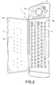
Fig. 2 shows a top view of a remote control device in accordance with the invention with the cover open. -
Fig. 3 shows a schematic diagram of the electric circuitry of the remote control device in accordance with the invention. -
Fig. 4 shows a flow chart of operations performed by a microprocessor which is shown inFig. 3 . -
Figs. 1 and2 show a top view of aremote control device 1 in accordance with the invention with acover 2 closed and open, respectively. The cover is attached to the device body by means of ahinge 3. As shown in the Figs., afirst keypad 4 is fixedly attached to the device body and the cover carries asecond keypad 5. - The
first keypad 4 is a full alphanumeric QWERTY keypad having a conventional layout. That is, the keys are arranged, and text on and next to the keys is printed, such that when the device is operated, its length axis is perpendicular to the imaginary line from the remote control device to the controlled appliance. Thesecond keypad 5 comprises keys for controlling the appliance in a conventional manner, for example, keys for entering a channel number, for incrementing or decrementing the volume or channel number, for controlling the tape function of a VCR, etc. The layout of this keypad is such that when the device is operated, its length axis is aimed towards the controlled appliance. A trackball ormousepad 10 for controlling a cursor is also provided. -
Fig. 1 further shows two infrared Light Emitting Diodes (LEDs), oneinfrared LED 7 being located at the top side of the device and emitting infrared light in adirection 7a corresponding to the device's length axis, and oneinfrared LED 8 being located at the left side and emitting infrared light in adirection 8a corresponding to the device's width axis. When the cover is open, it is blocked in a position so as not to impede the emission of light fromLED 8. - A
switch 9 is also shown in the Figs. Theswitch 9 comprises afirst member 9a which is fixedly attached to the device body and asecond member 9b which is fixedly attached to thecover 2. Upon closing the cover, bothmembers switch 9 is thus closed when the cover is closed. - The
second keypad 5 on thecover 2 may be an autonomous keypad. This is understood to mean that each key includes an individual sensor which, when the key is depressed, applies a corresponding signal to the device's electric circuitry through a flexible wiring arrangement (not shown). In a preferred embodiment, however, as shown inFig. 2 , thecover 2 includesholes 2a, one for each key. Through said holes, a protrusion of each key extends underneath the cover so as to mechanically activate the underlying key ofkeypad 4 if the cover is closed. For example, the key labeled "5" ofkeypad 5 activates the key labeled "J" ofkeypad 4. - A schematic diagram of the electric circuitry of the remote control device in accordance with the invention is shown in
Fig. 3 . Reference numerals already used before denote the same elements. The device comprises amicroprocessor 30 which is connected to thekeypad 4 and themembers switch 9 through various input and output port terminals. The microprocessor is further connected to adriver stage 37 for driving the top-LED 7 and to adriver stage 38 for driving the side-LED 8. The processor is also connected to a read-only-memory (ROM) 31 having amemory section 311 in which a first set of remote control command codes is stored, amemory section 312 in which a second set of remote control command codes is stored, and amemory section 313 in which a control program defining the operation of the processor is stored. The ROM may also be embedded in the microprocessor. - A flow chart of operations performed by the microprocessor is shown in
Fig. 4 . In astep 40, the processor scans thekeypad 4, awaits the depression of a key and identifies which key has been depressed. In astep 41, the processor checks whether theswitch 9 is closed. If the switch is not closed (i.e., thecover 2 is open), it is concluded that an alphanumeric key ofkeypad 4 is depressed. In that case the processor reads, in astep 42, the command code to be transmitted from thefirst memory section 311 ofROM 31. Then, in astep 43, the relevant command code is applied todriver stage 38 which drives the side-LED 8 so as to emit the infrared command signal in the direction of the width-axis 8a. If theswitch 9 is closed (i.e., thecover 2 is closed), it is concluded that a control key ofkeypad 5 is depressed. In that case the processor reads, in astep 44, the command code to be transmitted from thesecond memory section 312 ofROM 31. Then, in astep 45, the relevant command code is applied todriver stage 37 which drives the top-LED 7 so as to emit the infrared command signal in the direction of the length-axis 7a. Thus, if the alphanumeric key labeled "J" is depressed, a code for the letter "J" will be transmitted through side-LED 8. If the key labeled "5" on the cover is depressed, depression of the same alphanumeric key "J" is detected but, since theswitch 9 is now closed, a code for the channel select digit "5" will be transmitted through top-LED 7. - In summary, a remote control device (1) is disclosed for controlling a "Web-TV". The device has a first keypad (5) for controlling the conventional TV and VCR functions. The normal TV and VCR control commands are transmitted through a top-LED (7) in a first direction (7a). The keypad is accommodated on a cover (2). When the cover is open, a second keypad is accessible for entering alphanumeric data such as Web-addresses and e-mails. To use this QWERTY keypad in a convenient and familiar manner, the device is rotated through 90 degrees. In this operating mode (
Fig. 2 ), the key commands are transmitted through a side-LED (8) in a second direction (8a). A switch (9) detects whether the cover is open or closed and activates the relevant LED.
Claims (3)
- A handheld remote control device (1) comprising a first keypad for generating first control signals and a cover (2) which is slewably attached to the device and covers the first keypad (4) when it is closed, said cover carrying a second keypad (5) for generating second control signals, characterized in that the device has an elongated shape having a length axis and a width axis, the first keypad (4) being laid out for using the device in a first direction corresponding to said length axis or width axis, and the second keypad (5) being laid out for using a device in a second direction perpendicular to said first direction, that the device comprises emitting means (7, 8) for emitting the control signals in the form of directional beams, said emitting means including first emitting means (8) for emitting the first control signals in substantially the first direction and second emitting means (7) for emitting the second control signals in substantially the second direction, and further comprises detection means (9a,b) for detecting whether the cover is open or closed, the detection means being arranged to disable the second emitting means (8) if the cover is open and disable the first emitting means (7) if the cover is closed.
- A device as claimed in claim 1, wherein keys of the second keypad (5) protrude underneath the cover (2) so as to mechanically activate corresponding keys of the first keypad (4) when the cover is closed, the device further comprising detection means (9a, b) for detecting whether the cover is open or closed, the detection means being arranged to enable the first control signals to be generated if the cover is open and the second control signals to be generated if the cover is closed.
- A device as claimed in any one of the preceding claims, wherein the second keypad comprises keys for controlling respective functions of an electronic appliance, and the first keypad (4) is an alphanumeric keypad for applying alphanumeric data to said appliance.
Priority Applications (1)
| Application Number | Priority Date | Filing Date | Title |
|---|---|---|---|
| EP99917035A EP1000522B1 (en) | 1998-05-26 | 1999-05-14 | Remote control device |
Applications Claiming Priority (4)
| Application Number | Priority Date | Filing Date | Title |
|---|---|---|---|
| EP98201744 | 1998-05-26 | ||
| EP98201744 | 1998-05-26 | ||
| EP99917035A EP1000522B1 (en) | 1998-05-26 | 1999-05-14 | Remote control device |
| PCT/IB1999/000883 WO1999062287A2 (en) | 1998-05-26 | 1999-05-14 | Remote control device |
Publications (2)
| Publication Number | Publication Date |
|---|---|
| EP1000522A2 EP1000522A2 (en) | 2000-05-17 |
| EP1000522B1 true EP1000522B1 (en) | 2008-12-03 |
Family
ID=8233764
Family Applications (1)
| Application Number | Title | Priority Date | Filing Date |
|---|---|---|---|
| EP99917035A Expired - Lifetime EP1000522B1 (en) | 1998-05-26 | 1999-05-14 | Remote control device |
Country Status (5)
| Country | Link |
|---|---|
| EP (1) | EP1000522B1 (en) |
| KR (1) | KR100622289B1 (en) |
| DE (1) | DE69940008D1 (en) |
| TW (1) | TW386323B (en) |
| WO (1) | WO1999062287A2 (en) |
Cited By (28)
| Publication number | Priority date | Publication date | Assignee | Title |
|---|---|---|---|---|
| US8299695B2 (en) | 2009-06-02 | 2012-10-30 | Ilumisys, Inc. | Screw-in LED bulb comprising a base having outwardly projecting nodes |
| US8330381B2 (en) | 2009-05-14 | 2012-12-11 | Ilumisys, Inc. | Electronic circuit for DC conversion of fluorescent lighting ballast |
| US8362710B2 (en) | 2009-01-21 | 2013-01-29 | Ilumisys, Inc. | Direct AC-to-DC converter for passive component minimization and universal operation of LED arrays |
| US8421366B2 (en) | 2009-06-23 | 2013-04-16 | Ilumisys, Inc. | Illumination device including LEDs and a switching power control system |
| US8454193B2 (en) | 2010-07-08 | 2013-06-04 | Ilumisys, Inc. | Independent modules for LED fluorescent light tube replacement |
| US8523394B2 (en) | 2010-10-29 | 2013-09-03 | Ilumisys, Inc. | Mechanisms for reducing risk of shock during installation of light tube |
| US8540401B2 (en) | 2010-03-26 | 2013-09-24 | Ilumisys, Inc. | LED bulb with internal heat dissipating structures |
| US8541958B2 (en) | 2010-03-26 | 2013-09-24 | Ilumisys, Inc. | LED light with thermoelectric generator |
| US8556452B2 (en) | 2009-01-15 | 2013-10-15 | Ilumisys, Inc. | LED lens |
| US8596813B2 (en) | 2010-07-12 | 2013-12-03 | Ilumisys, Inc. | Circuit board mount for LED light tube |
| US8664880B2 (en) | 2009-01-21 | 2014-03-04 | Ilumisys, Inc. | Ballast/line detection circuit for fluorescent replacement lamps |
| US8807785B2 (en) | 2008-05-23 | 2014-08-19 | Ilumisys, Inc. | Electric shock resistant L.E.D. based light |
| US8870415B2 (en) | 2010-12-09 | 2014-10-28 | Ilumisys, Inc. | LED fluorescent tube replacement light with reduced shock hazard |
| US8928025B2 (en) | 2007-12-20 | 2015-01-06 | Ilumisys, Inc. | LED lighting apparatus with swivel connection |
| US9057493B2 (en) | 2010-03-26 | 2015-06-16 | Ilumisys, Inc. | LED light tube with dual sided light distribution |
| US9072171B2 (en) | 2011-08-24 | 2015-06-30 | Ilumisys, Inc. | Circuit board mount for LED light |
| US9101026B2 (en) | 2008-10-24 | 2015-08-04 | Ilumisys, Inc. | Integration of LED lighting with building controls |
| US9163794B2 (en) | 2012-07-06 | 2015-10-20 | Ilumisys, Inc. | Power supply assembly for LED-based light tube |
| US9184518B2 (en) | 2012-03-02 | 2015-11-10 | Ilumisys, Inc. | Electrical connector header for an LED-based light |
| US9271367B2 (en) | 2012-07-09 | 2016-02-23 | Ilumisys, Inc. | System and method for controlling operation of an LED-based light |
| US9267650B2 (en) | 2013-10-09 | 2016-02-23 | Ilumisys, Inc. | Lens for an LED-based light |
| US9285084B2 (en) | 2013-03-14 | 2016-03-15 | Ilumisys, Inc. | Diffusers for LED-based lights |
| US9353939B2 (en) | 2008-10-24 | 2016-05-31 | iLumisys, Inc | Lighting including integral communication apparatus |
| US9398661B2 (en) | 2008-10-24 | 2016-07-19 | Ilumisys, Inc. | Light and light sensor |
| US9510400B2 (en) | 2014-05-13 | 2016-11-29 | Ilumisys, Inc. | User input systems for an LED-based light |
| US9574717B2 (en) | 2014-01-22 | 2017-02-21 | Ilumisys, Inc. | LED-based light with addressed LEDs |
| US10161568B2 (en) | 2015-06-01 | 2018-12-25 | Ilumisys, Inc. | LED-based light with canted outer walls |
| US10176689B2 (en) | 2008-10-24 | 2019-01-08 | Ilumisys, Inc. | Integration of led lighting control with emergency notification systems |
Families Citing this family (10)
| Publication number | Priority date | Publication date | Assignee | Title |
|---|---|---|---|---|
| WO2005073939A1 (en) * | 2004-01-28 | 2005-08-11 | Clifford David Wilkinson | Remote control unit |
| KR101069765B1 (en) * | 2004-06-03 | 2011-10-04 | 엘지전자 주식회사 | (A) folder type of remote controller |
| US8208255B2 (en) | 2006-04-13 | 2012-06-26 | Toto Ltd | Remote control apparatus |
| JP4807262B2 (en) * | 2007-01-09 | 2011-11-02 | 船井電機株式会社 | Remote control device |
| FR2917515B1 (en) * | 2007-06-13 | 2010-05-14 | Archos Sa | WIRELESS REMOTE CONTROL DEVICE FOR NETWORK - CONNECTABLE MULTIMEDIA DIGITAL RECORDER RECEIVER AND SYSTEM THEREFOR. |
| EP2487663B1 (en) * | 2011-02-11 | 2014-12-31 | Fm Marketing GmbH | Remote control |
| US9734707B2 (en) * | 2012-01-09 | 2017-08-15 | Universal Electronics Inc. | Features for use with a multi-sided controlling device |
| TWM440603U (en) * | 2012-05-30 | 2012-11-01 | Hon Hai Prec Ind Co Ltd | Remote control device |
| KR101339035B1 (en) * | 2013-09-12 | 2013-12-09 | 리모트솔루션주식회사 | Folder type remocon |
| JP6573815B2 (en) * | 2015-10-19 | 2019-09-11 | 株式会社Lixil | Remote control device |
Family Cites Families (9)
| Publication number | Priority date | Publication date | Assignee | Title |
|---|---|---|---|---|
| JPS63117243U (en) * | 1987-01-26 | 1988-07-28 | ||
| DE3713428A1 (en) * | 1987-04-22 | 1988-11-03 | Unterhaltungselectronic Ohg De | Remote control unit for electrical devices |
| US5181024A (en) * | 1988-11-30 | 1993-01-19 | Kabushiki Kaisha Toshiba | Book type wireless remote control apparatus |
| US5534865A (en) * | 1992-11-20 | 1996-07-09 | Kriegsman; Irving M. | Ergonomic wireless remote control transmitter for use with consumer entertainment electronics appliance |
| JPH06189383A (en) * | 1992-12-16 | 1994-07-08 | Toshiba Corp | Wireless remote controller |
| DE19520947C5 (en) * | 1995-06-02 | 2012-04-05 | Constin Design Gmbh | Portable computer with telecommunication device |
| JP3172399B2 (en) * | 1995-08-01 | 2001-06-04 | 三洋電機株式会社 | Remote control device |
| JPH1032887A (en) * | 1996-07-15 | 1998-02-03 | Sanyo Electric Co Ltd | Two-way remote control transmitter |
| JPH10174178A (en) * | 1996-12-13 | 1998-06-26 | Sanyo Electric Co Ltd | Remote controller |
-
1998
- 1998-11-04 TW TW087118309A patent/TW386323B/en not_active IP Right Cessation
-
1999
- 1999-05-14 EP EP99917035A patent/EP1000522B1/en not_active Expired - Lifetime
- 1999-05-14 DE DE69940008T patent/DE69940008D1/en not_active Expired - Fee Related
- 1999-05-14 KR KR1020007000749A patent/KR100622289B1/en not_active IP Right Cessation
- 1999-05-14 WO PCT/IB1999/000883 patent/WO1999062287A2/en active IP Right Grant
Cited By (39)
| Publication number | Priority date | Publication date | Assignee | Title |
|---|---|---|---|---|
| US8928025B2 (en) | 2007-12-20 | 2015-01-06 | Ilumisys, Inc. | LED lighting apparatus with swivel connection |
| US8807785B2 (en) | 2008-05-23 | 2014-08-19 | Ilumisys, Inc. | Electric shock resistant L.E.D. based light |
| US9635727B2 (en) | 2008-10-24 | 2017-04-25 | Ilumisys, Inc. | Light and light sensor |
| US10036549B2 (en) | 2008-10-24 | 2018-07-31 | Ilumisys, Inc. | Lighting including integral communication apparatus |
| US9398661B2 (en) | 2008-10-24 | 2016-07-19 | Ilumisys, Inc. | Light and light sensor |
| US10342086B2 (en) | 2008-10-24 | 2019-07-02 | Ilumisys, Inc. | Integration of LED lighting with building controls |
| US9353939B2 (en) | 2008-10-24 | 2016-05-31 | iLumisys, Inc | Lighting including integral communication apparatus |
| US9585216B2 (en) | 2008-10-24 | 2017-02-28 | Ilumisys, Inc. | Integration of LED lighting with building controls |
| US9101026B2 (en) | 2008-10-24 | 2015-08-04 | Ilumisys, Inc. | Integration of LED lighting with building controls |
| US10176689B2 (en) | 2008-10-24 | 2019-01-08 | Ilumisys, Inc. | Integration of led lighting control with emergency notification systems |
| US10182480B2 (en) | 2008-10-24 | 2019-01-15 | Ilumisys, Inc. | Light and light sensor |
| US8556452B2 (en) | 2009-01-15 | 2013-10-15 | Ilumisys, Inc. | LED lens |
| US8362710B2 (en) | 2009-01-21 | 2013-01-29 | Ilumisys, Inc. | Direct AC-to-DC converter for passive component minimization and universal operation of LED arrays |
| US8664880B2 (en) | 2009-01-21 | 2014-03-04 | Ilumisys, Inc. | Ballast/line detection circuit for fluorescent replacement lamps |
| US8330381B2 (en) | 2009-05-14 | 2012-12-11 | Ilumisys, Inc. | Electronic circuit for DC conversion of fluorescent lighting ballast |
| US8299695B2 (en) | 2009-06-02 | 2012-10-30 | Ilumisys, Inc. | Screw-in LED bulb comprising a base having outwardly projecting nodes |
| US8421366B2 (en) | 2009-06-23 | 2013-04-16 | Ilumisys, Inc. | Illumination device including LEDs and a switching power control system |
| US8540401B2 (en) | 2010-03-26 | 2013-09-24 | Ilumisys, Inc. | LED bulb with internal heat dissipating structures |
| US9057493B2 (en) | 2010-03-26 | 2015-06-16 | Ilumisys, Inc. | LED light tube with dual sided light distribution |
| US9013119B2 (en) | 2010-03-26 | 2015-04-21 | Ilumisys, Inc. | LED light with thermoelectric generator |
| US8840282B2 (en) | 2010-03-26 | 2014-09-23 | Ilumisys, Inc. | LED bulb with internal heat dissipating structures |
| US8541958B2 (en) | 2010-03-26 | 2013-09-24 | Ilumisys, Inc. | LED light with thermoelectric generator |
| US9395075B2 (en) | 2010-03-26 | 2016-07-19 | Ilumisys, Inc. | LED bulb for incandescent bulb replacement with internal heat dissipating structures |
| US8454193B2 (en) | 2010-07-08 | 2013-06-04 | Ilumisys, Inc. | Independent modules for LED fluorescent light tube replacement |
| US8596813B2 (en) | 2010-07-12 | 2013-12-03 | Ilumisys, Inc. | Circuit board mount for LED light tube |
| US8523394B2 (en) | 2010-10-29 | 2013-09-03 | Ilumisys, Inc. | Mechanisms for reducing risk of shock during installation of light tube |
| US8894430B2 (en) | 2010-10-29 | 2014-11-25 | Ilumisys, Inc. | Mechanisms for reducing risk of shock during installation of light tube |
| US8870415B2 (en) | 2010-12-09 | 2014-10-28 | Ilumisys, Inc. | LED fluorescent tube replacement light with reduced shock hazard |
| US9072171B2 (en) | 2011-08-24 | 2015-06-30 | Ilumisys, Inc. | Circuit board mount for LED light |
| US9184518B2 (en) | 2012-03-02 | 2015-11-10 | Ilumisys, Inc. | Electrical connector header for an LED-based light |
| US9163794B2 (en) | 2012-07-06 | 2015-10-20 | Ilumisys, Inc. | Power supply assembly for LED-based light tube |
| US9271367B2 (en) | 2012-07-09 | 2016-02-23 | Ilumisys, Inc. | System and method for controlling operation of an LED-based light |
| US9807842B2 (en) | 2012-07-09 | 2017-10-31 | Ilumisys, Inc. | System and method for controlling operation of an LED-based light |
| US9285084B2 (en) | 2013-03-14 | 2016-03-15 | Ilumisys, Inc. | Diffusers for LED-based lights |
| US9267650B2 (en) | 2013-10-09 | 2016-02-23 | Ilumisys, Inc. | Lens for an LED-based light |
| US10260686B2 (en) | 2014-01-22 | 2019-04-16 | Ilumisys, Inc. | LED-based light with addressed LEDs |
| US9574717B2 (en) | 2014-01-22 | 2017-02-21 | Ilumisys, Inc. | LED-based light with addressed LEDs |
| US9510400B2 (en) | 2014-05-13 | 2016-11-29 | Ilumisys, Inc. | User input systems for an LED-based light |
| US10161568B2 (en) | 2015-06-01 | 2018-12-25 | Ilumisys, Inc. | LED-based light with canted outer walls |
Also Published As
| Publication number | Publication date |
|---|---|
| KR100622289B1 (en) | 2006-09-11 |
| WO1999062287A3 (en) | 2000-01-13 |
| DE69940008D1 (en) | 2009-01-15 |
| WO1999062287A2 (en) | 1999-12-02 |
| KR20010022177A (en) | 2001-03-15 |
| TW386323B (en) | 2000-04-01 |
| EP1000522A2 (en) | 2000-05-17 |
Similar Documents
| Publication | Publication Date | Title |
|---|---|---|
| EP1000522B1 (en) | Remote control device | |
| US5785439A (en) | Environmentally safe machine control security switch | |
| US7990288B2 (en) | Remote control device | |
| US5577848A (en) | Light controlled touch pad for cursor and selection control on a computer display | |
| KR100477126B1 (en) | Computer with optical dial function | |
| EP1209661B1 (en) | Universal remote control adapted to receive voice input | |
| US5986586A (en) | Keyboard with additional hot keys | |
| US6310608B1 (en) | System and method of keyboard configuration for disabled user access | |
| US5451953A (en) | Programmable remote control unit without extra key for configuration | |
| JPS61111074A (en) | Television camera | |
| MXPA00000795A (en) | Remote control device | |
| JP2003510715A (en) | Keyboard for electronic devices | |
| KR100505873B1 (en) | steering wheel having touch pad for working car audio | |
| KR100774513B1 (en) | Multi-function trackball mouse | |
| KR100453718B1 (en) | A portable keyboard | |
| KR100237242B1 (en) | Cursor control method of cursor controlling switch system | |
| KR100205816B1 (en) | Remote control transmission/receive system and pad-input method for key-pad input means | |
| KR0170142B1 (en) | Super remote controller | |
| KR200286424Y1 (en) | A portable keyboard | |
| KR0135471Y1 (en) | Error preventing apparatus of remocon system | |
| JP3526759B2 (en) | Keyboard for personal computer | |
| KR200327335Y1 (en) | Signal input apparatus for electronic products | |
| KR19990047538A (en) | Transmission code control method of VSI remote controller | |
| KR200404474Y1 (en) | Multi-function trackball mouse | |
| KR970003091Y1 (en) | Battery case |
Legal Events
| Date | Code | Title | Description |
|---|---|---|---|
| PUAI | Public reference made under article 153(3) epc to a published international application that has entered the european phase |
Free format text: ORIGINAL CODE: 0009012 |
|
| 17P | Request for examination filed |
Effective date: 20000228 |
|
| AK | Designated contracting states |
Kind code of ref document: A2 Designated state(s): BE DE FR GB |
|
| 17Q | First examination report despatched |
Effective date: 20060818 |
|
| GRAP | Despatch of communication of intention to grant a patent |
Free format text: ORIGINAL CODE: EPIDOSNIGR1 |
|
| GRAS | Grant fee paid |
Free format text: ORIGINAL CODE: EPIDOSNIGR3 |
|
| GRAS | Grant fee paid |
Free format text: ORIGINAL CODE: EPIDOSNIGR3 |
|
| GRAA | (expected) grant |
Free format text: ORIGINAL CODE: 0009210 |
|
| AK | Designated contracting states |
Kind code of ref document: B1 Designated state(s): BE DE FR GB |
|
| REG | Reference to a national code |
Ref country code: GB Ref legal event code: FG4D |
|
| REF | Corresponds to: |
Ref document number: 69940008 Country of ref document: DE Date of ref document: 20090115 Kind code of ref document: P |
|
| PG25 | Lapsed in a contracting state [announced via postgrant information from national office to epo] |
Ref country code: BE Free format text: LAPSE BECAUSE OF FAILURE TO SUBMIT A TRANSLATION OF THE DESCRIPTION OR TO PAY THE FEE WITHIN THE PRESCRIBED TIME-LIMIT Effective date: 20081203 |
|
| PLBE | No opposition filed within time limit |
Free format text: ORIGINAL CODE: 0009261 |
|
| STAA | Information on the status of an ep patent application or granted ep patent |
Free format text: STATUS: NO OPPOSITION FILED WITHIN TIME LIMIT |
|
| 26N | No opposition filed |
Effective date: 20090904 |
|
| GBPC | Gb: european patent ceased through non-payment of renewal fee |
Effective date: 20090514 |
|
| REG | Reference to a national code |
Ref country code: FR Ref legal event code: ST Effective date: 20100129 |
|
| PG25 | Lapsed in a contracting state [announced via postgrant information from national office to epo] |
Ref country code: FR Free format text: LAPSE BECAUSE OF NON-PAYMENT OF DUE FEES Effective date: 20090602 |
|
| PG25 | Lapsed in a contracting state [announced via postgrant information from national office to epo] |
Ref country code: GB Free format text: LAPSE BECAUSE OF NON-PAYMENT OF DUE FEES Effective date: 20090514 |
|
| PG25 | Lapsed in a contracting state [announced via postgrant information from national office to epo] |
Ref country code: DE Free format text: LAPSE BECAUSE OF NON-PAYMENT OF DUE FEES Effective date: 20091201 |