EP1000540A1 - Image processing - Google Patents
Image processing Download PDFInfo
- Publication number
- EP1000540A1 EP1000540A1 EP99650107A EP99650107A EP1000540A1 EP 1000540 A1 EP1000540 A1 EP 1000540A1 EP 99650107 A EP99650107 A EP 99650107A EP 99650107 A EP99650107 A EP 99650107A EP 1000540 A1 EP1000540 A1 EP 1000540A1
- Authority
- EP
- European Patent Office
- Prior art keywords
- vegetation
- enclosure
- image processing
- target area
- light
- Prior art date
- Legal status (The legal status is an assumption and is not a legal conclusion. Google has not performed a legal analysis and makes no representation as to the accuracy of the status listed.)
- Withdrawn
Links
Images


Classifications
-
- A—HUMAN NECESSITIES
- A01—AGRICULTURE; FORESTRY; ANIMAL HUSBANDRY; HUNTING; TRAPPING; FISHING
- A01M—CATCHING, TRAPPING OR SCARING OF ANIMALS; APPARATUS FOR THE DESTRUCTION OF NOXIOUS ANIMALS OR NOXIOUS PLANTS
- A01M7/00—Special adaptations or arrangements of liquid-spraying apparatus for purposes covered by this subclass
- A01M7/0089—Regulating or controlling systems
-
- A—HUMAN NECESSITIES
- A01—AGRICULTURE; FORESTRY; ANIMAL HUSBANDRY; HUNTING; TRAPPING; FISHING
- A01B—SOIL WORKING IN AGRICULTURE OR FORESTRY; PARTS, DETAILS, OR ACCESSORIES OF AGRICULTURAL MACHINES OR IMPLEMENTS, IN GENERAL
- A01B79/00—Methods for working soil
- A01B79/005—Precision agriculture
Definitions
- the invention relates to image processing for analysis of vegetation.
- fertilisers are typically spread in a blanket manner over all of the ground area.
- JP0707968 describes use of image processing in application of weedkiller. However, it appears that the arrangement described would have limited usefulness, particularly because of poor image quality.
- an image processing apparatus comprising means for moving over vegetation, means for capturing images of the vegetation, and means for processing said images and for generating an output signal for treatment of the vegetation, characterised in that:- the apparatus further comprises means for illuminating the vegetation at a target area, and a camera directed to capture images from the target area.
- the illumination means comprises means for illuminating a linear target area.
- the target area extends transversely with respect to the direction of travel of the apparatus.
- the illumination means comprises means for emitting a light beam at an acute angle in the range of 3° to 60° with respect to the horizontal. In one embodiment, the angle is in the range of 5° to 30°.
- the camera comprises a filter mounted to allow only light of an emitted wavelength to be captured
- the apparatus further comprises a ground-contacting enclosure to prevent entry of ambient light, and the illumination mean is mounted within the enclosure.
- the enclosure comprises lateral light seals extending in a longitudinal direction and comprising means for sliding on the ground.
- the light seals are tubular.
- the enclosure further comprises ground-contacting skirts extending transversely with respect to the direction of travel.
- the apparatus further comprises means for pressing down vegetation in the target area.
- Said pressing means may comprise a roller mounted forwardly of the target area.
- the image processing means comprises means for identifying plant varieties according to height and texture.
- the image processing means comprises means for dividing an image area into a plurality of zones corresponding to zones of an output device for treatment of vegetation.
- the apparatus comprises a weedkiller applicator and a controller for controlling the applicator for selective application of weedkiller according to identification of weeds by the image processing means.
- the apparatus further comprises a seed dispenser and the controller comprises means for controlling selective seed dispensing.
- the apparatus 1 comprises an enclosure 2 to create an environment free of ambient light for image processing to take place.
- the apparatus 1 is hauled to the left as viewed in Fig. 1 by use of a front frame 3 having a towing point 4, the height of which is adjustable by a spindle mechanism.
- the front frame 3 also supports a rubber skirt 5 extending transversely across the enclosure 2.
- a cylindrical roller 6 is mounted within the enclosure 2 at the front.
- a pair of wheels 7 are mounted at the rear of the enclosure 2 on the outside of it. Height of the wheels 7 is adjustable by operation of a spindle mechanism 8.
- a rear frame of the apparatus 1 also supports a rubber skirt 9 extending transversely at the rear wall of the enclosure 2. It also supports an outrigger 11, in turn supporting further skirts 10 extending transversely.
- the apparatus 1 also comprises a pair of lateral light seals 15, each comprising a rubber tube 16 and an upper steel guide 17 as shown in Fig. 2.
- the light seals 15 extend upwardly at the front in a sleigh-like configuration.
- the enclosure 2 supports four laser emitters 20 mounted in a line extending transversely across at the rear of the enclosure 2.
- Each laser emitter 20 comprises means for generating a fanned-out laser beam covering a transverse distance of approximately 0.6m and they are mounted so that together they illuminate the ground in a continuous line across the width of the enclosure 2.
- a camera 21 is mounted directly above each laser emitter 20 and is directed downwardly to the area of impingement of the associated laser light on the ground.
- the angle of incidence of the laser beams is in the range of 3° to 60° and is preferably in the range 5° to 30°. In this embodiment the angle is approximately 20°.
- the camera angle is approximately 45°.
- the image processing circuits include a dedicated image processor for each camera/laser pair.
- a controller 25 comprises image processing circuits connected to the laser emitters 20 and to the cameras 21.
- the controller 25 also comprises control circuits for a weedkiller spray boom 30 and a seed dispenser 35.
- the spray boom 30 comprises eight spray nozzles, each individually controlled by a solenoid value.
- the seed dispenser 35 comprises eight discrete dispensers, each also individually controlled by a solenoid value. The discrete spray areas and seed dispensing areas are defined as zones in the controller 25.
- the apparatus 1 is hauled to a site on the towing wheels 7.
- the site may, for example, be a grazing pasture in which there are weeds such as docks and couch grass.
- the wheels 7 are then raised using the mechanisms 8.
- the extent of raising determines the pressure exerted by the light seals 15 on the ground. This is selected according to the ground and vegetation conditions. Also, the towing height is selected according to the ground conditions.
- the apparatus 1 is then pulled so that it slides on the light seals 15, which act like a sleigh. Because of this they very effectively seal the enclosure by preventing entry of ambient light.
- the front skirt 5 and the rear skirts 9 and 10 are also very effective at sealing the enclosure from ambient light.
- the laser emitters 20 are activated to illuminate a line of light on the vegetation extending transversely across the enclosure.
- the vegetation which is illuminated is conditioned by being pressed down to a relatively flat orientation by the roller 6. This is very important for the image processing.
- a method 60 is performed by the controller 25 for each laser/camera pair. This includes the following steps, in which the numerals 61 to 69 correspond to those of Fig. 4. (Preconditions) Laser beam integrity verified Imaging enclosure security verified Spray system pressure verified Intensity normalisation array updated 61 Wait for Interrupt/or Clock/or Loop Process has three modes of operation - external interrupt, internal clock, and free running. External interrupt is from machine encoder, and is the mode used during field operation.
- 68, 69 When each spray zone has been processed, assemble all the spray control bits into a spray byte, and write it to the bottom of the Spray Control Shift Register (SCSR). Shift the SCSR up one. Read the top byte of the SCSR and write it to the Spray Boom Control Hardward. Write the same byte to the bottom of the Reseed Control Shift Register RCSR) Shift the RCSR up one. Read the top byte of the RCSR and write it to the Reseed Boom Control Hardware. Loop back to line 61.
- SCSR Spray Control Shift Register
- the controller 25 recognises weeds as the imaging enclosure 2 passes over them. It also activates the spray boom and the seed boom at exactly the right moment because it takes into account the speed of movement of the apparatus 1.
- the weedkiller which is sprayed from the boom 30 kills the weed and therefore prevents it from seeding if it has not already done so.
- the weedkiller does not affect the grass or other desired vegetation seed which are sown immediately afterwards and this allows grass or other desired vegetation to very quickly take over the area in which the weed was growing.
- the captured image provides sufficient information to make a determination as to the types of vegetation in the pasture.
- the controller 25 extracts from the image data relating to vegetation height, vegetation density, and the leaf and/or stem size of the vegetation.
- the desired image is achieved by enclosing the area of pasture to be imaged in the lightproof enclosure and illuminating the pasture with thin laser line across the full width of the imaged area.
- the angle of incidence of the laser light is generally low - most preferably in the region of 15 to 20 degrees to the ground.
- Each camera 21 is an area scan CCD camera positioned at a height above the laser, and generally at an angle of 45 degrees to the ground.
- the laser frequency is chosen to provide its peak output at a frequency at which the camera array is most sensitive.
- the camera lens is fitted with a filter which allows light at the laser frequency to pass, but obstructs other frequencies.
- the signal from the camera is passed to an image frame store which captures a complete image frame and makes it available for subsequent processing by the controller 25.
- the resultant image, as it would appear when the machine is positioned on bare ground, is shown in Fig. 5. If the ground were perfectly level then the line in the image would be completely straight. The undulating nature of the line is caused by natural variations in ground height.
- the shape of the laser line is modulated by the vegetation to provide a laser image which contains information about the pasture that can be extracted by the image processing techniques above.
- a sample image, such as would be obtained under these conditions is shown in Fig. 6.
- the result for each zone is analysed to determine whether a process should be applied to this zone.
- the result for all of the zones is assembled into a "spray byte" which is stored in a shift register.
- the shift register is clocked with input from the encoder to activate the process mechanism at the rear of the machine when it is aligned with the segment of pasture to which the spray byte relates.
- the invention provides for very effective weed removal. Weeds are killed selectively before they reach the stage of seeding. Also, the weed is replaced within a short period by grass or other desired vegetation without the need to spread the seed over a large area.
- the apparatus 1 allows very effective and efficient user of weedkiller and seed without adversely affecting yield of the desired crop.
- the apparatus need not include a roller as the frame and light skirt may sufficiently condition the vegetation.
- the apparatus may include a weedkilling device which operates to physically remove weeds instead of spraying them.
- the apparatus may operate to detect beneficial plants and selectively apply nutrients.
- the light seals may comprise steel tubes.
Abstract
An apparatus (1) has a light-sealing enclosure (2) which is drawn over vegetation on
sleigh-like light seals (15). The vegetation within the enclosure is conditioned by a
roller (6). Conditioned vegetation is illuminated in a transverse line by a set of four
laser emitters (20) and corresponding cameras (21) capture images. These images are
processed by analysis of height and texture data to identify weeds. A weedkiller
dispenser (30) selectively sprays weeds according to the image processing output. A
seed dispenser (35) selectively dispenses seed in the sprayed area to ensure desired
vegetation takes over the affected area.
Description
- The invention relates to image processing for analysis of vegetation.
- One of the oldest problems in farming of all types has been control of weeds because they inhibit growth of the desired plants and make harvesting more difficult. An example is the dock weed in pastures. The seeds of dock weeds can survive for several years and it is therefore extremely difficult to eradicate them from a pasture. Other weeds which commonly cause problems to farms are couch grass, hybrid grass, and clover.
- At present, the approach to weed control is general application of a "selective" weedkiller. However, problems with this approach are that the crop yield crop is often adversely affected and the weedkiller does not kill seeds in the ground.
- On the other hand, another problem encountered by farmers is that of efficiently applying fertilisers. At present, fertilisers are typically spread in a blanket manner over all of the ground area.
- Japanese Patent Specification No. JP0707968 describes use of image processing in application of weedkiller. However, it appears that the arrangement described would have limited usefulness, particularly because of poor image quality.
- It is therefore an object of the invention to provide an image processing apparatus for improved selective treatment of vegetation.
- According to the invention, there is provided an image processing apparatus comprising means for moving over vegetation, means for capturing images of the vegetation, and means for processing said images and for generating an output signal for treatment of the vegetation, characterised in that:-
the apparatus further comprises means for illuminating the vegetation at a target area, and a camera directed to capture images from the target area. - In one embodiment, the illumination means comprises means for illuminating a linear target area. Preferably, the target area extends transversely with respect to the direction of travel of the apparatus.
- In another embodiment, the illumination means comprises means for emitting a light beam at an acute angle in the range of 3° to 60° with respect to the horizontal. In one embodiment, the angle is in the range of 5° to 30°.
- In one embodiment, the camera comprises a filter mounted to allow only light of an emitted wavelength to be captured
- Preferably, the apparatus further comprises a ground-contacting enclosure to prevent entry of ambient light, and the illumination mean is mounted within the enclosure.
- In one embodiment, the enclosure comprises lateral light seals extending in a longitudinal direction and comprising means for sliding on the ground.
- In another embodiment, the light seals are tubular.
- In a further embodiment, the enclosure further comprises ground-contacting skirts extending transversely with respect to the direction of travel.
- Preferably, the apparatus further comprises means for pressing down vegetation in the target area.
- Said pressing means may comprise a roller mounted forwardly of the target area.
- In one embodiment, the image processing means comprises means for identifying plant varieties according to height and texture.
- In another embodiment, the image processing means comprises means for dividing an image area into a plurality of zones corresponding to zones of an output device for treatment of vegetation.
- In a further embodiment, the apparatus comprises a weedkiller applicator and a controller for controlling the applicator for selective application of weedkiller according to identification of weeds by the image processing means.
- In one embodiment, the apparatus further comprises a seed dispenser and the controller comprises means for controlling selective seed dispensing.
- The invention will be more clearly understood from the following description of some embodiments thereof, given by way of example only with reference to the accompanying drawings in which:-
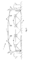
- Fig. 1 is a diagrammatic side view of an image processing apparatus of the invention;
- Fig. 2 is a cross-sectional view of a light seal of the apparatus;
- Fig. 3 is a diagrammatic front view of the apparatus;
- Fig. 4 is a flow diagram illustrating operation of a controller of the apparatus; and
- Figs. 5 and 6 are plots of reflected light for image processing.
-
- Referring to Figs. 1 to 3, an image processing apparatus 1 of the invention is illustrated. The apparatus 1 comprises an
enclosure 2 to create an environment free of ambient light for image processing to take place. The apparatus 1 is hauled to the left as viewed in Fig. 1 by use of afront frame 3 having a towing point 4, the height of which is adjustable by a spindle mechanism. Thefront frame 3 also supports arubber skirt 5 extending transversely across theenclosure 2. - A
cylindrical roller 6 is mounted within theenclosure 2 at the front. A pair ofwheels 7 are mounted at the rear of theenclosure 2 on the outside of it. Height of thewheels 7 is adjustable by operation of aspindle mechanism 8. A rear frame of the apparatus 1 also supports arubber skirt 9 extending transversely at the rear wall of theenclosure 2. It also supports anoutrigger 11, in turn supportingfurther skirts 10 extending transversely. - The apparatus 1 also comprises a pair of
lateral light seals 15, each comprising arubber tube 16 and anupper steel guide 17 as shown in Fig. 2. Thelight seals 15 extend upwardly at the front in a sleigh-like configuration. - The
enclosure 2 supports fourlaser emitters 20 mounted in a line extending transversely across at the rear of theenclosure 2. Eachlaser emitter 20 comprises means for generating a fanned-out laser beam covering a transverse distance of approximately 0.6m and they are mounted so that together they illuminate the ground in a continuous line across the width of theenclosure 2. - A
camera 21 is mounted directly above eachlaser emitter 20 and is directed downwardly to the area of impingement of the associated laser light on the ground. The angle of incidence of the laser beams is in the range of 3° to 60° and is preferably in therange 5° to 30°. In this embodiment the angle is approximately 20°. The camera angle is approximately 45°. The image processing circuits include a dedicated image processor for each camera/laser pair. - A
controller 25 comprises image processing circuits connected to thelaser emitters 20 and to thecameras 21. Thecontroller 25 also comprises control circuits for aweedkiller spray boom 30 and aseed dispenser 35. Thespray boom 30 comprises eight spray nozzles, each individually controlled by a solenoid value. Theseed dispenser 35 comprises eight discrete dispensers, each also individually controlled by a solenoid value. The discrete spray areas and seed dispensing areas are defined as zones in thecontroller 25. - In operation, the apparatus 1 is hauled to a site on the
towing wheels 7. The site may, for example, be a grazing pasture in which there are weeds such as docks and couch grass. Thewheels 7 are then raised using themechanisms 8. The extent of raising determines the pressure exerted by thelight seals 15 on the ground. This is selected according to the ground and vegetation conditions. Also, the towing height is selected according to the ground conditions. - The apparatus 1 is then pulled so that it slides on the light seals 15, which act like a sleigh. Because of this they very effectively seal the enclosure by preventing entry of ambient light. The
front skirt 5 and therear skirts - The
laser emitters 20 are activated to illuminate a line of light on the vegetation extending transversely across the enclosure. The vegetation which is illuminated is conditioned by being pressed down to a relatively flat orientation by theroller 6. This is very important for the image processing. - Referring to Figs 4 to 6, a
method 60 is performed by thecontroller 25 for each laser/camera pair. This includes the following steps, in which thenumerals 61 to 69 correspond to those of Fig. 4.(Preconditions) Laser beam integrity verified Imaging enclosure security verified Spray system pressure verified Intensity normalisation array updated 61 Wait for Interrupt/or Clock/or Loop Process has three modes of operation - external interrupt, internal clock, and free running. External interrupt is from machine encoder, and is the mode used during field operation. 62 Acquire image from camera Reset encoder interrupt counter 63 Extract laser line from image Normalise intensity levels 64 - 67 Process laser line as eight separate zones: For each zone: Divide into n segments (n <= 10) Measure and store depth of each segment Measure intensities of each segment Quantize and store segment intensity levels (n <= 128) Measure and store granularity of each segment Decide what the zone contains by applying the following rules to each segment: Docks - small depth, high average intensity, low quantization range, low granularity. Couch Grass - medium depth, medium average intensity, high quantization range, medium granularity. Hybrid Grass - large depth, low average intensity, low quantization range, high granularity. Clover - large depth, high average intensity, low quantization range, low granularity. Compute the percentage occupancy in the zone for each weed or by counting the results for each contiguous segment. Apply occupancy rules to avoid false positives. 68, 69 When each spray zone has been processed, assemble all the spray control bits into a spray byte, and write it to the bottom of the Spray Control Shift Register (SCSR). Shift the SCSR up one. Read the top byte of the SCSR and write it to the Spray Boom Control Hardward. Write the same byte to the bottom of the Reseed Control Shift Register RCSR) Shift the RCSR up one. Read the top byte of the RCSR and write it to the Reseed Boom Control Hardware. Loop back to line 61. - In this way, the
controller 25 recognises weeds as theimaging enclosure 2 passes over them. It also activates the spray boom and the seed boom at exactly the right moment because it takes into account the speed of movement of the apparatus 1. The weedkiller which is sprayed from theboom 30 kills the weed and therefore prevents it from seeding if it has not already done so. The weedkiller does not affect the grass or other desired vegetation seed which are sown immediately afterwards and this allows grass or other desired vegetation to very quickly take over the area in which the weed was growing. - As described above, the captured image provides sufficient information to make a determination as to the types of vegetation in the pasture. The
controller 25 extracts from the image data relating to vegetation height, vegetation density, and the leaf and/or stem size of the vegetation. The desired image is achieved by enclosing the area of pasture to be imaged in the lightproof enclosure and illuminating the pasture with thin laser line across the full width of the imaged area. In order to provide height and texture information, the angle of incidence of the laser light is generally low - most preferably in the region of 15 to 20 degrees to the ground. Eachcamera 21 is an area scan CCD camera positioned at a height above the laser, and generally at an angle of 45 degrees to the ground. The laser frequency is chosen to provide its peak output at a frequency at which the camera array is most sensitive. Additionally, the camera lens is fitted with a filter which allows light at the laser frequency to pass, but obstructs other frequencies. The signal from the camera is passed to an image frame store which captures a complete image frame and makes it available for subsequent processing by thecontroller 25. The resultant image, as it would appear when the machine is positioned on bare ground, is shown in Fig. 5. If the ground were perfectly level then the line in the image would be completely straight. The undulating nature of the line is caused by natural variations in ground height. - When another image is taken with the machine positioned over pasture with a representative vegetation sample, the shape of the laser line is modulated by the vegetation to provide a laser image which contains information about the pasture that can be extracted by the image processing techniques above. A sample image, such as would be obtained under these conditions is shown in Fig. 6.
- It is to be noted that:-
- (i) the height of the vegetation is determined by measuring the deflection of the laser line from a nominal base line, and
- (ii) the texture of the vegetation, and subsequently its leaf and stem size and its growth density, is determined by examining the texture of the laser line.
-
- When the image is read into a computer for processing the following operations are performed upon it in order to extract the information that is required to identify the various plant types:
- The area occupied by the laser line is determined by a search for the upper and lower limits of the laser line. Then this is defined as the region of interest (ROI) for further processing.
- The ROI is divided into eight horizontal zones corresponding in size on the image to the area of action of the spray and/or reseed mechanisms at the rear of the machine. The image is processed to remove noise.
- The average height of the vegetation in each zone is measured by measuring the deflection of the laser line in the Y direction from a nominal base line. A number of measurements are taken for each zone, and these are used to define the "envelope" for each zone.
- The number of discrete image objects in each zone is ascertained.
- The size, position and shape of each object in each zone is determined.
- Using the height, size and shape data for each object, and the distribution of these objects within each zone, a determination of the nature of each object is made.
- The following general rules are applied in order to allow the system to apply
voting techniques as to the possible outcome:
- Clusters of small sized objects at a low height with a high population density exhibiting small height variation:- couch grass.
- Clusters of small sized objects at medium to high height with a medium population density exhibiting large height variation:- rye grass.
- Clusters of medium sized objects at medium height with a medium to high population density and significant object overlap, and medium to high height variation:- clover.
- Medium objects of medium height exhibiting heightened intensity values, of varying shape and below a given size limit:- dandelion.
- Large objects of medium height exhibiting height intensity values, of varying shape and above a certain size limit:- dock.
- Large object of low height exhibiting high intensity values, of regular shape, with little variation in the Y direction, and above a certain size limit:- bare ground.
- When the entire signal has been processed, the result for each zone is analysed to determine whether a process should be applied to this zone. The result for all of the zones is assembled into a "spray byte" which is stored in a shift register. The shift register is clocked with input from the encoder to activate the process mechanism at the rear of the machine when it is aligned with the segment of pasture to which the spray byte relates.
- It will be appreciated that the invention provides for very effective weed removal. Weeds are killed selectively before they reach the stage of seeding. Also, the weed is replaced within a short period by grass or other desired vegetation without the need to spread the seed over a large area. The apparatus 1 allows very effective and efficient user of weedkiller and seed without adversely affecting yield of the desired crop.
- The invention is not limited to the embodiments described but may be varied in construction and detail within the scope of the claims. For example, the apparatus need not include a roller as the frame and light skirt may sufficiently condition the vegetation. Also, the apparatus may include a weedkilling device which operates to physically remove weeds instead of spraying them. The apparatus may operate to detect beneficial plants and selectively apply nutrients. Also, the light seals may comprise steel tubes.
Claims (15)
- An image processing apparatus comprising means for moving over vegetation, means for capturing images of the vegetation, and means for processing said images and for generating an output signal for treatment of the vegetation, characterised in that:-
the apparatus further comprises means (20) for illuminating the vegetation at a target area, and a camera (21) directed to capture images from the target area. - An apparatus as claimed in claim 1, wherein the illumination means comprises means (20) for illuminating a linear target area.
- An apparatus as claimed in claim 2, wherein the target area extends transversely with respect to the direction of travel of the apparatus.
- An apparatus as claimed in any preceding claim, wherein the illumination means comprises means for emitting a light beam at an acute angle in the range of 3° to 60°, and preferably 5° to 30° with respect to the horizontal.
- An apparatus as claimed in any preceding claim, wherein the camera comprises a filter mounted to allow only light of an emitted wavelength to be captured.
- An apparatus as claimed in any preceding claim, wherein the apparatus further comprises a ground-contacting enclosure to prevent entry of ambient light, and the illumination mean is mounted within the enclosure.
- An apparatus as claimed in claim 6, wherein the enclosure comprises lateral light seals extending in a longitudinal direction and comprising means for sliding on the ground.
- An apparatus as claimed in claim 7, wherein the light seals are tubular.
- An apparatus as claimed in any of claims 6 to 8, wherein the enclosure further comprises ground-contacting skirts extending transversely with respect to the direction of travel.
- An apparatus as claimed in any preceding claim, wherein the apparatus further comprises means for pressing down vegetation in the target area.
- An apparatus as claimed in claim 10, wherein said pressing means comprises a roller mounted forwardly of the target area.
- An apparatus as claimed in any preceding claim, wherein the image processing means comprises means for identifying plant varieties according to height and texture.
- An apparatus as claimed in claim 12, wherein the image processing means comprises means for dividing an image area into a plurality of zones corresponding to zones of an output device for treatment of vegetation.
- An apparatus as claimed in any preceding claim, wherein the apparatus comprises a weedkiller applicator and a controller for controlling the applicator for selective application of weedkiller according to identification of weeds by the image processing means.
- An apparatus as claimed in claim 14, wherein the apparatus further comprises a seed dispenser and the controller comprises means for controlling selective seed dispensing.
Applications Claiming Priority (2)
| Application Number | Priority Date | Filing Date | Title |
|---|---|---|---|
| IE980940 | 1998-11-16 | ||
| IE980940 | 1998-11-16 |
Publications (1)
| Publication Number | Publication Date |
|---|---|
| EP1000540A1 true EP1000540A1 (en) | 2000-05-17 |
Family
ID=11041925
Family Applications (1)
| Application Number | Title | Priority Date | Filing Date |
|---|---|---|---|
| EP99650107A Withdrawn EP1000540A1 (en) | 1998-11-16 | 1999-11-15 | Image processing |
Country Status (1)
| Country | Link |
|---|---|
| EP (1) | EP1000540A1 (en) |
Cited By (14)
| Publication number | Priority date | Publication date | Assignee | Title |
|---|---|---|---|---|
| WO2006117581A1 (en) * | 2005-04-29 | 2006-11-09 | G & G Növényvédelmi és Kereskedelmi Kft. | Setup for constructing a weed map |
| NO325927B1 (en) * | 2005-07-08 | 2008-08-18 | Dimensions Agri Technologies As | System for controlled herbicide feeding |
| WO2010126879A1 (en) * | 2009-04-29 | 2010-11-04 | Monsanto Technology Llc | Biometric measurement systems and methods |
| CN103940465A (en) * | 2014-01-28 | 2014-07-23 | 安徽大学 | Weed information acquisition method and system |
| AU2013203361B2 (en) * | 2012-04-11 | 2015-05-21 | Capstan Ag Systems, Inc. | System for spraying plants and/or plant precursors |
| CN105045302A (en) * | 2015-07-27 | 2015-11-11 | 北京农业智能装备技术研究中心 | Soil application device based on laser positioning and method |
| WO2016125198A1 (en) * | 2015-02-02 | 2016-08-11 | Casini Diego | Harvester for leafy vegetables perfected with electronic sorter |
| WO2017178666A1 (en) * | 2016-04-12 | 2017-10-19 | Diego Hernan Perez Roca | Autonomous set of devices and method for detecting and identifying plant species in an agricultural crop for the selective application of agrochemicals |
| WO2019129333A1 (en) * | 2017-12-29 | 2019-07-04 | Agro Intelligence Aps | Apparatus and method for improving the yield of grass and clover harvested from an agricultural field |
| CN110754458A (en) * | 2019-09-26 | 2020-02-07 | 浙江海洋大学 | Automatic laser imaging pesticide spraying robot |
| CN111225855A (en) * | 2017-10-17 | 2020-06-02 | 巴斯夫欧洲公司 | Unmanned plane |
| WO2021009710A1 (en) * | 2019-07-16 | 2021-01-21 | Bilberry Sas | System for treating plants for use in agriculture |
| US11832609B2 (en) | 2020-12-21 | 2023-12-05 | Deere & Company | Agricultural sprayer with real-time, on-machine target sensor |
| US11944087B2 (en) | 2020-12-21 | 2024-04-02 | Deere & Company | Agricultural sprayer with real-time, on-machine target sensor |
Citations (5)
| Publication number | Priority date | Publication date | Assignee | Title |
|---|---|---|---|---|
| WO1991003148A1 (en) * | 1989-08-30 | 1991-03-21 | Knudsen Joergen Elkjaer | Method and device for dosing for instance fertilizers, chemicals and/or seed grain in a field |
| DE4446481A1 (en) * | 1994-12-23 | 1996-06-27 | Ortloff Peter | Measurement and control system for identifying plants for contaminant free weeding and treatment of field |
| US5621460A (en) * | 1994-10-11 | 1997-04-15 | Lockheed Martin Corporation | Optical differentiation between plants and background utilizing a single CCD camera |
| WO1997037372A1 (en) * | 1996-04-03 | 1997-10-09 | Patchen, Inc. | Apparatus and method for spraying herbicide on weeds in a cotton field |
| DE19723770A1 (en) * | 1997-06-06 | 1998-12-10 | Hydro Agri Deutschland Gmbh | Plant condition measuring device |
-
1999
- 1999-11-15 EP EP99650107A patent/EP1000540A1/en not_active Withdrawn
Patent Citations (5)
| Publication number | Priority date | Publication date | Assignee | Title |
|---|---|---|---|---|
| WO1991003148A1 (en) * | 1989-08-30 | 1991-03-21 | Knudsen Joergen Elkjaer | Method and device for dosing for instance fertilizers, chemicals and/or seed grain in a field |
| US5621460A (en) * | 1994-10-11 | 1997-04-15 | Lockheed Martin Corporation | Optical differentiation between plants and background utilizing a single CCD camera |
| DE4446481A1 (en) * | 1994-12-23 | 1996-06-27 | Ortloff Peter | Measurement and control system for identifying plants for contaminant free weeding and treatment of field |
| WO1997037372A1 (en) * | 1996-04-03 | 1997-10-09 | Patchen, Inc. | Apparatus and method for spraying herbicide on weeds in a cotton field |
| DE19723770A1 (en) * | 1997-06-06 | 1998-12-10 | Hydro Agri Deutschland Gmbh | Plant condition measuring device |
Cited By (23)
| Publication number | Priority date | Publication date | Assignee | Title |
|---|---|---|---|---|
| US8107681B2 (en) | 2005-04-29 | 2012-01-31 | G & G Növényvédelmi és Kereskedelmi K ft. | Setup for constructing a weed map |
| WO2006117581A1 (en) * | 2005-04-29 | 2006-11-09 | G & G Növényvédelmi és Kereskedelmi Kft. | Setup for constructing a weed map |
| NO325927B1 (en) * | 2005-07-08 | 2008-08-18 | Dimensions Agri Technologies As | System for controlled herbicide feeding |
| US8454245B2 (en) | 2005-07-08 | 2013-06-04 | Dimensions Agri Technologies As | System for controlled application of herbicides |
| US9423249B2 (en) | 2009-04-29 | 2016-08-23 | Monsanto Technology Llc | Biometric measurement systems and methods |
| WO2010126879A1 (en) * | 2009-04-29 | 2010-11-04 | Monsanto Technology Llc | Biometric measurement systems and methods |
| EP2424344A1 (en) * | 2009-04-29 | 2012-03-07 | Monsanto Technology LLC | Biometric measurement systems and methods |
| US20120113225A1 (en) * | 2009-04-29 | 2012-05-10 | Monsanto Technology Llc | Biometric measurement systems and methods |
| AU2013203361B2 (en) * | 2012-04-11 | 2015-05-21 | Capstan Ag Systems, Inc. | System for spraying plants and/or plant precursors |
| US10925206B2 (en) | 2012-04-11 | 2021-02-23 | Capstan Ag Systems, Inc. | System for spraying plants and/or plant precursors |
| CN103940465A (en) * | 2014-01-28 | 2014-07-23 | 安徽大学 | Weed information acquisition method and system |
| WO2016125198A1 (en) * | 2015-02-02 | 2016-08-11 | Casini Diego | Harvester for leafy vegetables perfected with electronic sorter |
| CN105045302B (en) * | 2015-07-27 | 2017-07-25 | 北京农业智能装备技术研究中心 | Soil pesticide device and method based on laser positioning |
| CN105045302A (en) * | 2015-07-27 | 2015-11-11 | 北京农业智能装备技术研究中心 | Soil application device based on laser positioning and method |
| WO2017178666A1 (en) * | 2016-04-12 | 2017-10-19 | Diego Hernan Perez Roca | Autonomous set of devices and method for detecting and identifying plant species in an agricultural crop for the selective application of agrochemicals |
| CN111225855A (en) * | 2017-10-17 | 2020-06-02 | 巴斯夫欧洲公司 | Unmanned plane |
| US20200241568A1 (en) * | 2017-10-17 | 2020-07-30 | Basf Se | Unmanned aerial vehicle |
| WO2019129333A1 (en) * | 2017-12-29 | 2019-07-04 | Agro Intelligence Aps | Apparatus and method for improving the yield of grass and clover harvested from an agricultural field |
| WO2021009710A1 (en) * | 2019-07-16 | 2021-01-21 | Bilberry Sas | System for treating plants for use in agriculture |
| FR3098684A1 (en) * | 2019-07-16 | 2021-01-22 | Bilberry Sas | Plant treatment system in agriculture |
| CN110754458A (en) * | 2019-09-26 | 2020-02-07 | 浙江海洋大学 | Automatic laser imaging pesticide spraying robot |
| US11832609B2 (en) | 2020-12-21 | 2023-12-05 | Deere & Company | Agricultural sprayer with real-time, on-machine target sensor |
| US11944087B2 (en) | 2020-12-21 | 2024-04-02 | Deere & Company | Agricultural sprayer with real-time, on-machine target sensor |
Similar Documents
| Publication | Publication Date | Title |
|---|---|---|
| EP1000540A1 (en) | Image processing | |
| US20220022360A1 (en) | Method and Apparatus for Automated Plant Necrosis | |
| RU2767347C2 (en) | Method of applying a spraying agent on a field | |
| US7417731B1 (en) | Scanning sensor-identifier and standard set-up | |
| US6601341B2 (en) | Process for in-season fertilizer nitrogen application based on predicted yield potential | |
| Tian et al. | Development of a precision sprayer for site-specific weed management | |
| US20210329906A1 (en) | Apparatus for spraying insecticides | |
| CN112839511B (en) | Method for applying a spray to a field | |
| EP3298385B1 (en) | Plant matter sensor | |
| AU2020103332A4 (en) | IMLS-Weed Recognition/Classification: Intelligent Weed Recognition /Classification using Machine Learning System | |
| BR102019027103A2 (en) | process for distributing a spray medicine over an agricultural area | |
| Steward et al. | Machine-vision weed density estimation for real-time, outdoor lighting conditions | |
| IE990949A1 (en) | Image Processing | |
| Doruchowski et al. | Target detection as a tool of selective spray application on trees and weeds in orchards | |
| Giles et al. | Development of a machine vision system for weed control using precision chemical application | |
| CN113971759A (en) | Device and method for automatically identifying weeds among soybean plants based on computer vision | |
| CN113418509A (en) | Automatic target-aiming detection device and detection method for agriculture | |
| BE1027164A1 (en) | PLANTING MACHINE | |
| Esau et al. | Supplementary light source development for camera-based smart spraying in low light conditions | |
| Lamm | Robotic weed control for cotton | |
| RU2795590C2 (en) | Insecticide sprayer | |
| Sadjadi | Applications of image understanding technology in precision agriculture: Weed classification, and crop row guidance | |
| EP4358710A1 (en) | Apperatus and method for measuring insect activity | |
| DE102023127962A1 (en) | System and procedure for using agronomic data | |
| AU2020481684A1 (en) | Systems and methods for using backscatter imaging in precision agriculture |
Legal Events
| Date | Code | Title | Description |
|---|---|---|---|
| PUAI | Public reference made under article 153(3) epc to a published international application that has entered the european phase |
Free format text: ORIGINAL CODE: 0009012 |
|
| AK | Designated contracting states |
Kind code of ref document: A1 Designated state(s): AT BE CH CY DE DK ES FI FR GB GR IE IT LI LU MC NL PT SE |
|
| AX | Request for extension of the european patent |
Free format text: AL;LT;LV;MK;RO;SI |
|
| 17P | Request for examination filed |
Effective date: 20001113 |
|
| AKX | Designation fees paid |
Free format text: AT BE CH CY DE DK ES FI FR GB GR IE IT LI LU MC NL PT SE |
|
| STAA | Information on the status of an ep patent application or granted ep patent |
Free format text: STATUS: THE APPLICATION IS DEEMED TO BE WITHDRAWN |
|
| 18D | Application deemed to be withdrawn |
Effective date: 20020601 |