EP1000819B1 - Method and apparatus for determining time to fire an occupant restraint system using occupant sensor inputs - Google Patents
Method and apparatus for determining time to fire an occupant restraint system using occupant sensor inputs Download PDFInfo
- Publication number
- EP1000819B1 EP1000819B1 EP99308842A EP99308842A EP1000819B1 EP 1000819 B1 EP1000819 B1 EP 1000819B1 EP 99308842 A EP99308842 A EP 99308842A EP 99308842 A EP99308842 A EP 99308842A EP 1000819 B1 EP1000819 B1 EP 1000819B1
- Authority
- EP
- European Patent Office
- Prior art keywords
- occupant
- crash
- position signal
- displacement
- signal
- Prior art date
- Legal status (The legal status is an assumption and is not a legal conclusion. Google has not performed a legal analysis and makes no representation as to the accuracy of the status listed.)
- Expired - Lifetime
Links
Images


Classifications
-
- B—PERFORMING OPERATIONS; TRANSPORTING
- B60—VEHICLES IN GENERAL
- B60R—VEHICLES, VEHICLE FITTINGS, OR VEHICLE PARTS, NOT OTHERWISE PROVIDED FOR
- B60R21/00—Arrangements or fittings on vehicles for protecting or preventing injuries to occupants or pedestrians in case of accidents or other traffic risks
- B60R21/01—Electrical circuits for triggering passive safety arrangements, e.g. airbags, safety belt tighteners, in case of vehicle accidents or impending vehicle accidents
- B60R21/013—Electrical circuits for triggering passive safety arrangements, e.g. airbags, safety belt tighteners, in case of vehicle accidents or impending vehicle accidents including means for detecting collisions, impending collisions or roll-over
- B60R21/0132—Electrical circuits for triggering passive safety arrangements, e.g. airbags, safety belt tighteners, in case of vehicle accidents or impending vehicle accidents including means for detecting collisions, impending collisions or roll-over responsive to vehicle motion parameters, e.g. to vehicle longitudinal or transversal deceleration or speed value
- B60R21/01332—Electrical circuits for triggering passive safety arrangements, e.g. airbags, safety belt tighteners, in case of vehicle accidents or impending vehicle accidents including means for detecting collisions, impending collisions or roll-over responsive to vehicle motion parameters, e.g. to vehicle longitudinal or transversal deceleration or speed value by frequency or waveform analysis
- B60R21/01336—Electrical circuits for triggering passive safety arrangements, e.g. airbags, safety belt tighteners, in case of vehicle accidents or impending vehicle accidents including means for detecting collisions, impending collisions or roll-over responsive to vehicle motion parameters, e.g. to vehicle longitudinal or transversal deceleration or speed value by frequency or waveform analysis using filtering
-
- B—PERFORMING OPERATIONS; TRANSPORTING
- B60—VEHICLES IN GENERAL
- B60R—VEHICLES, VEHICLE FITTINGS, OR VEHICLE PARTS, NOT OTHERWISE PROVIDED FOR
- B60R21/00—Arrangements or fittings on vehicles for protecting or preventing injuries to occupants or pedestrians in case of accidents or other traffic risks
- B60R21/01—Electrical circuits for triggering passive safety arrangements, e.g. airbags, safety belt tighteners, in case of vehicle accidents or impending vehicle accidents
- B60R21/013—Electrical circuits for triggering passive safety arrangements, e.g. airbags, safety belt tighteners, in case of vehicle accidents or impending vehicle accidents including means for detecting collisions, impending collisions or roll-over
- B60R21/0132—Electrical circuits for triggering passive safety arrangements, e.g. airbags, safety belt tighteners, in case of vehicle accidents or impending vehicle accidents including means for detecting collisions, impending collisions or roll-over responsive to vehicle motion parameters, e.g. to vehicle longitudinal or transversal deceleration or speed value
- B60R21/0133—Electrical circuits for triggering passive safety arrangements, e.g. airbags, safety belt tighteners, in case of vehicle accidents or impending vehicle accidents including means for detecting collisions, impending collisions or roll-over responsive to vehicle motion parameters, e.g. to vehicle longitudinal or transversal deceleration or speed value by integrating the amplitude of the input signal
-
- B—PERFORMING OPERATIONS; TRANSPORTING
- B60—VEHICLES IN GENERAL
- B60R—VEHICLES, VEHICLE FITTINGS, OR VEHICLE PARTS, NOT OTHERWISE PROVIDED FOR
- B60R21/00—Arrangements or fittings on vehicles for protecting or preventing injuries to occupants or pedestrians in case of accidents or other traffic risks
- B60R21/01—Electrical circuits for triggering passive safety arrangements, e.g. airbags, safety belt tighteners, in case of vehicle accidents or impending vehicle accidents
- B60R21/015—Electrical circuits for triggering passive safety arrangements, e.g. airbags, safety belt tighteners, in case of vehicle accidents or impending vehicle accidents including means for detecting the presence or position of passengers, passenger seats or child seats, and the related safety parameters therefor, e.g. speed or timing of airbag inflation in relation to occupant position or seat belt use
- B60R21/01512—Passenger detection systems
- B60R21/0153—Passenger detection systems using field detection presence sensors
-
- B—PERFORMING OPERATIONS; TRANSPORTING
- B60—VEHICLES IN GENERAL
- B60R—VEHICLES, VEHICLE FITTINGS, OR VEHICLE PARTS, NOT OTHERWISE PROVIDED FOR
- B60R21/00—Arrangements or fittings on vehicles for protecting or preventing injuries to occupants or pedestrians in case of accidents or other traffic risks
- B60R21/01—Electrical circuits for triggering passive safety arrangements, e.g. airbags, safety belt tighteners, in case of vehicle accidents or impending vehicle accidents
- B60R21/015—Electrical circuits for triggering passive safety arrangements, e.g. airbags, safety belt tighteners, in case of vehicle accidents or impending vehicle accidents including means for detecting the presence or position of passengers, passenger seats or child seats, and the related safety parameters therefor, e.g. speed or timing of airbag inflation in relation to occupant position or seat belt use
- B60R21/01512—Passenger detection systems
- B60R21/01544—Passenger detection systems detecting seat belt parameters, e.g. length, tension or height-adjustment
- B60R21/01546—Passenger detection systems detecting seat belt parameters, e.g. length, tension or height-adjustment using belt buckle sensors
-
- B—PERFORMING OPERATIONS; TRANSPORTING
- B60—VEHICLES IN GENERAL
- B60R—VEHICLES, VEHICLE FITTINGS, OR VEHICLE PARTS, NOT OTHERWISE PROVIDED FOR
- B60R21/00—Arrangements or fittings on vehicles for protecting or preventing injuries to occupants or pedestrians in case of accidents or other traffic risks
- B60R21/01—Electrical circuits for triggering passive safety arrangements, e.g. airbags, safety belt tighteners, in case of vehicle accidents or impending vehicle accidents
- B60R21/015—Electrical circuits for triggering passive safety arrangements, e.g. airbags, safety belt tighteners, in case of vehicle accidents or impending vehicle accidents including means for detecting the presence or position of passengers, passenger seats or child seats, and the related safety parameters therefor, e.g. speed or timing of airbag inflation in relation to occupant position or seat belt use
- B60R21/01512—Passenger detection systems
- B60R21/01544—Passenger detection systems detecting seat belt parameters, e.g. length, tension or height-adjustment
- B60R21/01548—Passenger detection systems detecting seat belt parameters, e.g. length, tension or height-adjustment sensing the amount of belt winded on retractor
-
- B—PERFORMING OPERATIONS; TRANSPORTING
- B60—VEHICLES IN GENERAL
- B60R—VEHICLES, VEHICLE FITTINGS, OR VEHICLE PARTS, NOT OTHERWISE PROVIDED FOR
- B60R21/00—Arrangements or fittings on vehicles for protecting or preventing injuries to occupants or pedestrians in case of accidents or other traffic risks
- B60R21/01—Electrical circuits for triggering passive safety arrangements, e.g. airbags, safety belt tighteners, in case of vehicle accidents or impending vehicle accidents
- B60R21/015—Electrical circuits for triggering passive safety arrangements, e.g. airbags, safety belt tighteners, in case of vehicle accidents or impending vehicle accidents including means for detecting the presence or position of passengers, passenger seats or child seats, and the related safety parameters therefor, e.g. speed or timing of airbag inflation in relation to occupant position or seat belt use
- B60R21/01554—Seat position sensors
-
- B—PERFORMING OPERATIONS; TRANSPORTING
- B60—VEHICLES IN GENERAL
- B60R—VEHICLES, VEHICLE FITTINGS, OR VEHICLE PARTS, NOT OTHERWISE PROVIDED FOR
- B60R21/00—Arrangements or fittings on vehicles for protecting or preventing injuries to occupants or pedestrians in case of accidents or other traffic risks
- B60R21/01—Electrical circuits for triggering passive safety arrangements, e.g. airbags, safety belt tighteners, in case of vehicle accidents or impending vehicle accidents
- B60R2021/01013—Means for detecting collision, impending collision or roll-over
- B60R2021/0102—Means for detecting collision, impending collision or roll-over the monitored value being used for calculating occupant displacement
Definitions
- the present invention relates to a method and apparatus for optimising firing time of an occupant restraint system, and more particularly to an advanced restraint system algorithm using occupant sensor inputs to modify firing time of an air bag.
- An advanced restraint system is to provide an optimal protection system for an occupant involved in a vehicle impact.
- the systems involved in the task of restraining an occupant have all. worked independently without any feedback between systems.
- a popular design uses a seat belt system that is designed to do the majority of the work of restraining an occupant.
- An air bag is deployed based on a vehicle crash pulse generated during a crash, which is sensed by a crash sensor. Deployment occurs at 30ms prior to the point at which a properly seated, properly positioned occupant is expected to have moved five inches (or 500mm).
- the air bag provides a restraining force that supplements the seat belt restraint.
- the ideal system would have the seat belt start restraining the occupant until a certain load limit is reached. At that point, the air bag would have been deployed by the crash sensor and be ready to provide a supplemental restraining force.
- occupant sensors have been proposed that provide feedback to a control system independently of the crash sensor and prevent or augment deployment of the air bag restraint if the occupant is out of position.
- this does not incorporate the crash sensor into a control loop, but rather the control algorithms still fire the air bag based upon the vehicle-specific 5-30 rule for time to fire (TTF), as explained above, so the crash sensor and occupant sensor work independently.
- TTF time to fire
- crash sensor accelerometer does not always provide an accurate estimate of the occupant's "free body motion". Also, it is well known that crash algorithms use various integral methods to estimate occupant movement, but these estimates do not incorporate real time feedback of occupant position.
- the invention provides apparatus for controlling an occupant restraint system including an air bag, the apparatus comprising: a crash sensor having an accelerometer for producing a crash signal and including an adjustable filter; an occupant position sensing system for measuring occupant position and producing a position signal; and a controller operatively connected to said crash sensor and occupant position sensing system, wherein the controller incorporates an algorithm for determining an appropriate time to fire the air bag based upon said crash signal and position signal, characterised in that: the algorithm is operative to perform the steps of: calculating an estimated occupant displacement by integrating the crash signal twice; comparing said estimated occupant displacement to the position signal; and adjusting the adjustable filter based upon said comparing step to determine the appropriate time to fire the air bag.
- the present invention also provides a method for determining time to fire an occupant restraint system using a crash sensor having an accelerometer which produces an accelerometer signal, and with an occupant position sensor which produces a position signal, wherein the crash sensor includes an adjustable filter, the method characterised by: calculating an estimated occupant displacement by integrating the accelerometer signal twice; comparing the estimated occupant displacement to the position signal; and adjusting the adjustable filter based upon the comparing step so that the estimated occupant displacement closely correlates with the position signal, thereby optimising control of the occupant restraint system.
- the step of adjusting the adjustable filter is performed such that lower frequencies of acceleration are twice integrated, which provides optimal firing of the air bag.
- the adjustment comprises using lower frequency high pass filter coefficients if the position signal leads the estimated occupant displacement, and using higher frequency high pass filter coefficients if the position signal lags the estimated occupant displacement.
- Embodiments of the invention use the occupant position sensor in conjunction with a crash sensor accelerometer to augment the occupant restraint firing system.
- embodiments of the invention provide an adaptive, closed loop control system which adjusts a crash sensor filter based upon a comparison between the double integral of the crash sensor accelerometer and the occupant position sensor signal.
- a vehicle 10 is shown schematically incorporating an advanced restraint system in accordance with the present invention.
- the system shown in Figure 1 is for illustrative purposes only, and is not intended to be limiting. It is understood that the present invention may be used with a wide variety of occupant restraining systems.
- the vehicle 10 includes a seat 12 having a seat back 14 and a lower seat 16.
- a seat belt 18 is attached to a belt buckle 20 including a switch 22 operatively connected to a main controller 24.
- the seat belt 18 is also connected to a floor mount 26, which incorporates a belt payout sensor 28 and a belt controller 30, which are each electrically connected to the main controller 24.
- the seat 12 also includes a seat position sensor 32, and a seat back angle sensor 34, each of which are connected to the main controller 24. Any variety of sensors may be used with the present invention, such as infrared sensors, etc.
- the vehicle 10 also includes an instrument panel 38 having an inflatable air bag 40 mounted within a housing 42, and deployable by an inflator 44 for deploying the air bag to the inflated position 40', shown in phantom in Figure 1.
- a venting device 46 is provided in communication with the housing 44 for venting a desired amount of inflation fluid away from the air bag 40 to facilitate a desired inflation amount.
- the instrument panel 36 also includes an occupant position sensor 48 which is in electrical communication with the controller 24, and a crash sensor 50 including an accelerometer, which is also electrically connected with the controller 24.
- a crash sensor 50 including an accelerometer, which is also electrically connected with the controller 24.
- an occupant position sensor may be used for sensing a driver or passenger position.
- the crash sensor 50 also includes an adjustable filter 52 associated with the accelerometer.
- the present invention is particularly characterised in the algorithm of the controller 24 which uses signals from the occupant position sensors 36,48 and the crash sensor 50 to improve timeliness of air bag deployment.
- a dynamic occupant position sensing system in accordance with the present invention determines the occupant's instantaneous position and continuously compares this measured signal with the second integral of the crash sensor accelerometer 50 signal, which estimates the free body position of the occupant.
- the term "second integral" may refer to an appropriate analogue or digital calculation, or may be determined by a mathematical model of any kind.
- Figure 2 shows a displacement versus time graphical illustration of actual head position (line A) with the second integral of the acceleration signal from a crash sensor (line B). It is apparent from this illustration that, for a 35 mph barrier crash, the two measurements track each other almost identically throughout the crash event.
- Figure 3 shows the same two curves, but for a more "real world” event, namely a 45 mph car-to-car crash.
- the head position A leads the second integral B by as much as one inch, or 20% at the time to fire (TTF).
- TTF time to fire
- a high pass filter may be analogous to a magnet which pulls a ball back to its original position within a tube of a "ball and tube" crash sensor, which prevents a small event such as curb hop, from firing the air bag. The magnetic force is strong enough to pull the ball back into its original position.
- a high pass filter does the same to accelerometer data.
- the same curb hop event causes a pulse of acceleration, and without a high pass filter it would take only a few hundred milliseconds to reach a threshold to fire the air bag. Therefore, the data must be continuously reset to avoid such an inadvertent air bag firing.
- curb hop situation is an illustration of a condition in which implementation of the crash sensor technology cannot match the real world. Also, all such integration-type sensing must operate with the limitation that the integration data must be continuously reset.
- the cut-off frequency for high pass filtering is the critical choice. If a frequency is selected too high, one runs the risk of not being sensitive enough to long duration velocity change crashes because these lower frequency signals are attenuated by the filter. Conversely, if a cut-off frequency is selected which is too low, one runs the risk of easily reaching deployment thresholds due to inadvertent events, such as curb hop followed by a braking event.
- the present invention contemplates the combination of examining the occupant's position and always comparing it to the second integral of the electronic crash sensor accelerometer 50.
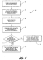
- the control algorithm 60 for this strategy is shown in Figure 4.
- the crash sensor accelerometer data is sampled, and an estimated occupant displacement is calculated from the accelerometer data at step 64 by calculating the double integral of the accelerometer signal.
- the occupant position sensor data is sampled, and this data is compared to the estimated displacement at step 68.
- a determination is made whether the occupant position sensor data is greater than or equal to the accelerometer estimated displacement value.
- the occupant position sensor lags the estimated accelerometer displacement data, and higher frequency high pass filter coefficients are selected for the adjustable filter 52, as illustrated at step 72. If the answer to decision block 70 is "yes”, then the occupant position leads the estimated accelerometer displacement data, and lower frequency high pass filter coefficients are selected for the adjustable filter 52 at step 74.
- the high pass filter is shown as component 52 in. Figure 1.
- the high pass filter frequency is adjusted, for example, from 3 Hz down to 0.3 Hz.
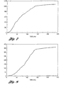
- the .3 Hz and 3 Hz high pass frequency situations are illustrated graphically as force versus time in Figures 5 and 6, respectively.
- Figures 7 and 8 are integrations of Figures 5 and 6, respectively. These graphs demonstrate the effect the different filters have on the velocity calculations, which are commonly used as crash sensor firing metrics. An overlay of Figures 7 and 8 would illustrate that the 3 Hz high pass filter frequency has more content removed from the signal in the mid-range than the 0.3 Hz high pass filter frequency, which is desirable when the occupant position lags the accelerometer displacement data.
- the above-described algorithm improves the accuracy in predicting and measuring the occupant's pre-crash position in the vehicle, which optimises an advanced restraint system by optimising the time at which the air bag is deployed.
Description
- The present invention relates to a method and apparatus for optimising firing time of an occupant restraint system, and more particularly to an advanced restraint system algorithm using occupant sensor inputs to modify firing time of an air bag.
- The objective of an advanced restraint system is to provide an optimal protection system for an occupant involved in a vehicle impact. Until now, the systems involved in the task of restraining an occupant have all. worked independently without any feedback between systems. A popular design uses a seat belt system that is designed to do the majority of the work of restraining an occupant. An air bag is deployed based on a vehicle crash pulse generated during a crash, which is sensed by a crash sensor. Deployment occurs at 30ms prior to the point at which a properly seated, properly positioned occupant is expected to have moved five inches (or 500mm). The air bag provides a restraining force that supplements the seat belt restraint.
- The ideal system would have the seat belt start restraining the occupant until a certain load limit is reached. At that point, the air bag would have been deployed by the crash sensor and be ready to provide a supplemental restraining force.
- To accomplish this system objective, occupant sensors have been proposed that provide feedback to a control system independently of the crash sensor and prevent or augment deployment of the air bag restraint if the occupant is out of position. However, this does not incorporate the crash sensor into a control loop, but rather the control algorithms still fire the air bag based upon the vehicle-specific 5-30 rule for time to fire (TTF), as explained above, so the crash sensor and occupant sensor work independently.
- The crash sensor accelerometer does not always provide an accurate estimate of the occupant's "free body motion". Also, it is well known that crash algorithms use various integral methods to estimate occupant movement, but these estimates do not incorporate real time feedback of occupant position.
- It is desirable to provide a system which more accurately determines the "free body motion" of the vehicle occupant so that the optimal firing time of the air bag can be more accurately determined.
- The invention provides apparatus for controlling an occupant restraint system including an air bag, the apparatus comprising: a crash sensor having an accelerometer for producing a crash signal and including an adjustable filter; an occupant position sensing system for measuring occupant position and producing a position signal; and a controller operatively connected to said crash sensor and occupant position sensing system, wherein the controller incorporates an algorithm for determining an appropriate time to fire the air bag based upon said crash signal and position signal, characterised in that: the algorithm is operative to perform the steps of: calculating an estimated occupant displacement by integrating the crash signal twice; comparing said estimated occupant displacement to the position signal; and adjusting the adjustable filter based upon said comparing step to determine the appropriate time to fire the air bag.
- The present invention also provides a method for determining time to fire an occupant restraint system using a crash sensor having an accelerometer which produces an accelerometer signal, and with an occupant position sensor which produces a position signal, wherein the crash sensor includes an adjustable filter, the method characterised by: calculating an estimated occupant displacement by integrating the accelerometer signal twice; comparing the estimated occupant displacement to the position signal; and adjusting the adjustable filter based upon the comparing step so that the estimated occupant displacement closely correlates with the position signal, thereby optimising control of the occupant restraint system.
- Preferably, the step of adjusting the adjustable filter is performed such that lower frequencies of acceleration are twice integrated, which provides optimal firing of the air bag. In other words, the adjustment comprises using lower frequency high pass filter coefficients if the position signal leads the estimated occupant displacement, and using higher frequency high pass filter coefficients if the position signal lags the estimated occupant displacement.
- Embodiments of the invention use the occupant position sensor in conjunction with a crash sensor accelerometer to augment the occupant restraint firing system.
- Furthermore, embodiments of the invention provide an adaptive, closed loop control system which adjusts a crash sensor filter based upon a comparison between the double integral of the crash sensor accelerometer and the occupant position sensor signal.
- The invention will now be described further, by way of example, with reference to the accompanying drawings, in which:
- Figure 1 shows a schematic side view of a vehicle incorporating an advanced restraint system in accordance with the present invention;
- Figure 2 shows a graphical illustration of displacement vs. time for a 35 mph barrier test;
- Figure 3 shows a graphical illustration of displacement vs. time for a 45 mph car-to-car crash;
- Figure 4 shows a flow chart of a control algorithm for an advanced restraint system in accordance with the present invention;
- Figure 5 shows a graphical illustration of force vs. time in an advanced restraint system implementing a .3 Hz high pass filter in accordance with the present invention;
- Figure 6 shows a graphical illustration of force vs. time in an advanced restraint system implementing a 3 Hz high pass filter in accordance with the present invention;
- Figure 7 illustrates velocity vs. time integrated from the data of Figure 5; and
- Figure 8 shows velocity vs. time integrated from the data of Figure 6.
-
- Referring to Figure 1, a
vehicle 10 is shown schematically incorporating an advanced restraint system in accordance with the present invention. The system shown in Figure 1 is for illustrative purposes only, and is not intended to be limiting. It is understood that the present invention may be used with a wide variety of occupant restraining systems. - As shown, the
vehicle 10 includes aseat 12 having a seat back 14 and alower seat 16. Aseat belt 18 is attached to abelt buckle 20 including aswitch 22 operatively connected to amain controller 24. Theseat belt 18 is also connected to afloor mount 26, which incorporates abelt payout sensor 28 and abelt controller 30, which are each electrically connected to themain controller 24. Theseat 12 also includes aseat position sensor 32, and a seatback angle sensor 34, each of which are connected to themain controller 24. Any variety of sensors may be used with the present invention, such as infrared sensors, etc. - The
vehicle 10 also includes an instrument panel 38 having aninflatable air bag 40 mounted within ahousing 42, and deployable by aninflator 44 for deploying the air bag to the inflated position 40', shown in phantom in Figure 1. Aventing device 46 is provided in communication with thehousing 44 for venting a desired amount of inflation fluid away from theair bag 40 to facilitate a desired inflation amount. - The
instrument panel 36 also includes anoccupant position sensor 48 which is in electrical communication with thecontroller 24, and acrash sensor 50 including an accelerometer, which is also electrically connected with thecontroller 24. Of course, an occupant position sensor may be used for sensing a driver or passenger position. Thecrash sensor 50 also includes anadjustable filter 52 associated with the accelerometer. - Details regarding the structure and function of the various components listed above, as well as additional supporting background disclosure, may be found in U.S. Patent Nos. 5,413,378, 5,439,249, 5,546,307, 5,537,422, and 5,626,359 (preambles of
claims 1 and 4). - The present invention is particularly characterised in the algorithm of the
controller 24 which uses signals from theoccupant position sensors crash sensor 50 to improve timeliness of air bag deployment. In particular, a dynamic occupant position sensing system in accordance with the present invention determines the occupant's instantaneous position and continuously compares this measured signal with the second integral of thecrash sensor accelerometer 50 signal, which estimates the free body position of the occupant. As used herein, the term "second integral" may refer to an appropriate analogue or digital calculation, or may be determined by a mathematical model of any kind. - By way of background information, Figure 2 shows a displacement versus time graphical illustration of actual head position (line A) with the second integral of the acceleration signal from a crash sensor (line B). It is apparent from this illustration that, for a 35 mph barrier crash, the two measurements track each other almost identically throughout the crash event.
- Figure 3 shows the same two curves, but for a more "real world" event, namely a 45 mph car-to-car crash. In this event, the head position A leads the second integral B by as much as one inch, or 20% at the time to fire (TTF). One reason that this "lead" occurs is that the velocity change of the vehicle takes place over a longer period of time, which is more representative of a real-world crash as compared to a barrier crash. Other factors, such as whether the occupant is properly belted, in proper position, or not belted at all, will affect the lead or lag. This long velocity pulse allows for increased displacement of the occupant at lower deceleration values. In this situation, air bag deployment would be later than desired.
- Another issue that exacerbates the above scenario is that in a single point electronic crash sensor, high pass filtering is required to reset or re-establish the integral and other algorithm calculations, which would further separate the two curves. This filtering is needed so that saturation does not occur due to the constants developed from integration. There exists no physical representation of a high pass filter in the real world. A high pass filter may be analogous to a magnet which pulls a ball back to its original position within a tube of a "ball and tube" crash sensor, which prevents a small event such as curb hop, from firing the air bag. The magnetic force is strong enough to pull the ball back into its original position. A high pass filter does the same to accelerometer data. For instance, the same curb hop event causes a pulse of acceleration, and without a high pass filter it would take only a few hundred milliseconds to reach a threshold to fire the air bag. Therefore, the data must be continuously reset to avoid such an inadvertent air bag firing.
- The curb hop situation is an illustration of a condition in which implementation of the crash sensor technology cannot match the real world. Also, all such integration-type sensing must operate with the limitation that the integration data must be continuously reset.
- The method by which continuous algorithmic systems, such as electronic crash sensors, implement high pass filtering is the major consideration. The cut-off frequency for high pass filtering is the critical choice. If a frequency is selected too high, one runs the risk of not being sensitive enough to long duration velocity change crashes because these lower frequency signals are attenuated by the filter. Conversely, if a cut-off frequency is selected which is too low, one runs the risk of easily reaching deployment thresholds due to inadvertent events, such as curb hop followed by a braking event.
- The present invention contemplates the combination of examining the occupant's position and always comparing it to the second integral of the electronic
crash sensor accelerometer 50. Thecontrol algorithm 60 for this strategy is shown in Figure 4. Atstep 62, the crash sensor accelerometer data is sampled, and an estimated occupant displacement is calculated from the accelerometer data atstep 64 by calculating the double integral of the accelerometer signal. Atstep 66, the occupant position sensor data is sampled, and this data is compared to the estimated displacement atstep 68. Atstep 70, a determination is made whether the occupant position sensor data is greater than or equal to the accelerometer estimated displacement value. If the answer is "no", then the occupant position sensor lags the estimated accelerometer displacement data, and higher frequency high pass filter coefficients are selected for theadjustable filter 52, as illustrated atstep 72. If the answer todecision block 70 is "yes", then the occupant position leads the estimated accelerometer displacement data, and lower frequency high pass filter coefficients are selected for theadjustable filter 52 atstep 74. - For example, when the occupant position leads the second integral of the crash sensor accelerometer, one would employ an adaptive filtering method to adjust the value of the adjustable high pass filter frequency from its initial value. The high pass filter is shown as
component 52 in. Figure 1. In this situation, with the occupant position leading the second integral of the crash sensor accelerometer signal, the high pass filter frequency is adjusted, for example, from 3 Hz down to 0.3 Hz. The .3 Hz and 3 Hz high pass frequency situations are illustrated graphically as force versus time in Figures 5 and 6, respectively. By adjusting from 3 Hz down to 0.3 Hz, a more sensitive algorithm is provided for sensing a long velocity duration crash, which is the type of crash that is more common in the field. - Figures 7 and 8 are integrations of Figures 5 and 6, respectively. These graphs demonstrate the effect the different filters have on the velocity calculations, which are commonly used as crash sensor firing metrics. An overlay of Figures 7 and 8 would illustrate that the 3 Hz high pass filter frequency has more content removed from the signal in the mid-range than the 0.3 Hz high pass filter frequency, which is desirable when the occupant position lags the accelerometer displacement data.
- The above-described algorithm improves the accuracy in predicting and measuring the occupant's pre-crash position in the vehicle, which optimises an advanced restraint system by optimising the time at which the air bag is deployed.
Claims (7)
- An apparatus for controlling an occupant restraint system including an air bag (40), the apparatus comprising:wherein the controller (24) incorporates an algorithm for determining an appropriate time to fire the air bag (40) based upon said crash signal and position signal,a crash sensor (50) having an accelerometer for producing a crash signal and including an adjustable filter; an occupant position sensing system (48) for measuring occupant position and producing a position signal; anda controller (24) operatively connected to said crash sensor (50) and occupant position sensing system (48),
characterised in that:the algorithm is operative to perform the following steps:calculating an estimated occupant displacement by integrating the crash signal twice;comparing said estimated occupant displacement to the position signal; andadjusting the adjustable filter based upon said comparing step to determine the appropriate time to fire the air bag. - An apparatus as claimed in claim 1, wherein said algorithm operation of adjusting the adjustable filter comprises using lower frequency high pass filter coefficients if the position signal leads the estimated occupant displacement.
- An apparatus as claimed in claim 1, wherein said algorithm operation of adjusting the adjustable filter comprises using higher frequency high pass filter coefficients if the position signal lags the estimated occupant displacement.
- A method for determining time to fire an occupant restraint system operatively connected with a crash sensor having an accelerometer which produces an accelerometer signal, and with an occupant position sensor which produces a position signal, wherein the crash sensor includes an adjustable filter, the method characterised by:calculating an estimated occupant displacement by integrating the accelerometer signal twice;comparing said estimated occupant displacement to the position signal; andadjusting the adjustable filter based upon said comparing step so that said estimated occupant displacement closely correlates with the position signal, thereby optimising control of the occupant restraint system.
- A method as claimed in claim 4, wherein said step of adjusting the adjustable filter comprises using lower frequency high pass filter coefficients if the position signal leads the estimated occupant displacement.
- A method as claimed in claim 4, wherein said step of adjusting the adjustable filter comprises using higher frequency high pass filter coefficients if the position signal lags the estimated occupant displacement.
- A method as claimed in claim 4, wherein said comparing step comprises:comparing said estimated occupant displacement to the position signal to determine whether a particular crash event is of long duration; andadjusting the adjustable filter to optimise early firing time of the occupant restraint system.
Applications Claiming Priority (2)
| Application Number | Priority Date | Filing Date | Title |
|---|---|---|---|
| US09/190,595 US6188940B1 (en) | 1998-11-12 | 1998-11-12 | Method and apparatus for determining time to fire an occupant restraint system using occupant sensor inputs |
| US190595 | 1998-11-12 |
Publications (3)
| Publication Number | Publication Date |
|---|---|
| EP1000819A2 EP1000819A2 (en) | 2000-05-17 |
| EP1000819A3 EP1000819A3 (en) | 2001-01-31 |
| EP1000819B1 true EP1000819B1 (en) | 2004-05-26 |
Family
ID=22701993
Family Applications (1)
| Application Number | Title | Priority Date | Filing Date |
|---|---|---|---|
| EP99308842A Expired - Lifetime EP1000819B1 (en) | 1998-11-12 | 1999-11-05 | Method and apparatus for determining time to fire an occupant restraint system using occupant sensor inputs |
Country Status (4)
| Country | Link |
|---|---|
| US (1) | US6188940B1 (en) |
| EP (1) | EP1000819B1 (en) |
| JP (1) | JP4342052B2 (en) |
| DE (1) | DE69917562T2 (en) |
Families Citing this family (25)
| Publication number | Priority date | Publication date | Assignee | Title |
|---|---|---|---|---|
| US6581961B1 (en) * | 1999-12-17 | 2003-06-24 | Trw Vehicle Safety Systems Inc. | Deactivation of second stage of air bag inflator |
| US6550806B1 (en) * | 2000-04-19 | 2003-04-22 | Trw Inc. | Apparatus and method for determining distance utilizing a continuously variable rate sensor for vehicle occupant position sensing |
| US6370461B1 (en) * | 2000-06-27 | 2002-04-09 | Ford Global Technologies, Inc. | Crash control system for vehicles employing predictive pre-crash signals |
| JP2002357476A (en) * | 2001-03-26 | 2002-12-13 | Takata Corp | Seat weight measurement device |
| DE60209238T2 (en) * | 2001-07-18 | 2006-11-16 | Intier Automotive Inc., Aurora | SEAT RAIL WITH BUILT-IN POSITION SENSOR FOR A MOTOR VEHICLE |
| DE10246055A1 (en) * | 2002-10-02 | 2004-04-15 | Robert Bosch Gmbh | Protection device for a vehicle occupant |
| DE102004017066A1 (en) * | 2004-04-07 | 2005-10-27 | Daimlerchrysler Ag | Motor vehicle with positioning means for vehicle occupants |
| US7322605B2 (en) * | 2004-07-09 | 2008-01-29 | Intier Automotive Inc. | Seat track assembly for a motor vehicle having an integrated position sensor |
| GB2416896B (en) * | 2004-07-22 | 2009-03-11 | Autoliv Dev | Improvements in or relating to a safety arrangement |
| DE102005026775A1 (en) * | 2005-06-10 | 2006-12-28 | Bayerische Motoren Werke Ag | Vehicle has restraining device, sensor device, and electronics which is a control electronics, which controls a control variable (F(t), A(t)) of restraining device depending on one measured variable |
| DE102005050505A1 (en) * | 2005-10-21 | 2007-04-26 | Bayerische Motoren Werke Ag | Passenger restraining system with airbag in motor vehicle has control unit designed to decide about triggering airbag depending on signals of crash sensor, seat position recognition system and belt length detector |
| US8478488B2 (en) * | 2006-03-28 | 2013-07-02 | Ford Global Technologies | Impact event countermeasure control method and system for automotive vehicle |
| JP2008247277A (en) * | 2007-03-30 | 2008-10-16 | Takata Corp | Control method for occupant constraint system, and occupant constraint system |
| JP5166779B2 (en) * | 2007-06-18 | 2013-03-21 | タカタ株式会社 | Air bag, air bag device, and air bag exhaust method |
| US7991552B2 (en) | 2008-11-06 | 2011-08-02 | Ford Global Technologies, Llc | System and method for determining a side-impact collision status of a nearby vehicle |
| US7991551B2 (en) | 2008-11-06 | 2011-08-02 | Ford Global Technologies, Llc | System and method for determining a collision status of a nearby vehicle |
| KR101486022B1 (en) * | 2008-12-15 | 2015-01-23 | 현대모비스 주식회사 | Restriction device's control method for the front of passenger |
| DE102009037619A1 (en) | 2009-08-14 | 2011-02-17 | Continental Automotive Gmbh | Method for signal processing of structure-borne sound signals, in particular in motor vehicles, and occupant protection system with corresponding signal processing unit |
| KR101305896B1 (en) * | 2011-07-19 | 2013-09-06 | 서강대학교산학협력단 | Active safety apparatus for vehicle |
| US9849852B1 (en) | 2015-09-04 | 2017-12-26 | Waymo Llc | Intelligent deployment of safety mechanisms for autonomous vehicles |
| US9802568B1 (en) | 2015-09-04 | 2017-10-31 | Waymo Llc | Interlocking vehicle airbags |
| US9817397B1 (en) | 2015-09-04 | 2017-11-14 | Waymo Llc | Active safety mechanisms for an autonomous vehicle |
| US11203318B2 (en) | 2018-06-18 | 2021-12-21 | Waymo Llc | Airbag extension system |
| EP4297999A1 (en) * | 2021-02-26 | 2024-01-03 | ZF Friedrichshafen AG | System and method for estimating occupant movement in response to automatic emergency braking |
| EP4349662A1 (en) * | 2022-10-06 | 2024-04-10 | Veoneer Sweden Safety Systems AB | Method for occupant restraint control on board of a vehicle |
Family Cites Families (12)
| Publication number | Priority date | Publication date | Assignee | Title |
|---|---|---|---|---|
| US5546307A (en) | 1989-05-30 | 1996-08-13 | Trw Vehicle Safety Systems Inc. | Method and apparatus for discriminating vehicle crash conditions |
| DE4212421A1 (en) * | 1992-04-14 | 1993-10-28 | Bosch Gmbh Robert | Method and device for protecting vehicle occupants |
| JP3428039B2 (en) | 1992-06-30 | 2003-07-22 | ソニー株式会社 | Synchronous signal detector, synchronous signal detecting method and decoding device |
| US5626359A (en) | 1993-12-02 | 1997-05-06 | Trw Vehicle Safety Systems, Inc. | Method and apparatus for controlling an actuatable restraining device in response to discrete control zones |
| US5439249A (en) | 1993-12-02 | 1995-08-08 | Trw Vehicle Safety Systems Inc. | Vehicle occupant restraint system including occupant position sensor mounted in seat back |
| US5413378A (en) | 1993-12-02 | 1995-05-09 | Trw Vehicle Safety Systems Inc. | Method and apparatus for controlling an actuatable restraining device in response to discrete control zones |
| US5770997A (en) * | 1995-06-26 | 1998-06-23 | Alliedsignal Inc. | Vehicle occupant sensing system |
| US5935182A (en) * | 1996-09-24 | 1999-08-10 | Trw Inc. | Method and apparatus for discriminating a vehicle crash using virtual sensing |
| US6056079A (en) * | 1996-12-19 | 2000-05-02 | Automotive Systems Laboratory, Inc. | Automotive seat weight sensing system |
| US5928300A (en) * | 1997-10-30 | 1999-07-27 | Simula Inc. | Three-axis aircraft crash sensing system |
| US5991234A (en) * | 1998-06-11 | 1999-11-23 | Trw Inc. | Ultrasonic sensor system and method having automatic excitation frequency adjustment |
| US6036225A (en) * | 1998-07-01 | 2000-03-14 | Trw Inc. | Method and apparatus for controlling an actuatable restraint device using crash severity indexing |
-
1998
- 1998-11-12 US US09/190,595 patent/US6188940B1/en not_active Expired - Fee Related
-
1999
- 1999-10-25 JP JP30294799A patent/JP4342052B2/en not_active Expired - Fee Related
- 1999-11-05 EP EP99308842A patent/EP1000819B1/en not_active Expired - Lifetime
- 1999-11-05 DE DE69917562T patent/DE69917562T2/en not_active Expired - Lifetime
Also Published As
| Publication number | Publication date |
|---|---|
| EP1000819A3 (en) | 2001-01-31 |
| DE69917562D1 (en) | 2004-07-01 |
| US6188940B1 (en) | 2001-02-13 |
| EP1000819A2 (en) | 2000-05-17 |
| JP2000142309A (en) | 2000-05-23 |
| JP4342052B2 (en) | 2009-10-14 |
| DE69917562T2 (en) | 2005-08-04 |
Similar Documents
| Publication | Publication Date | Title |
|---|---|---|
| EP1000819B1 (en) | Method and apparatus for determining time to fire an occupant restraint system using occupant sensor inputs | |
| US6529810B2 (en) | Method and apparatus for controlling an actuatable restraining device using switched thresholds based on transverse acceleration | |
| US5997033A (en) | Adaptive airbag inflation method and apparatus | |
| JP3481429B2 (en) | Vehicle collision determination method and apparatus using virtual sensing | |
| US5967548A (en) | Safety arrangement | |
| JP3217791B2 (en) | How to distinguish long-term low-speed collisions | |
| US6282474B1 (en) | Method and apparatus for detecting rollover of an automotive vehicle | |
| US5906393A (en) | Occupant restraint system and control method with variable sense, sample, and determination rates | |
| US6776435B2 (en) | Method and apparatus for controlling an actuatable restraining device using switched thresholds based on crush zone sensors | |
| US6882914B2 (en) | Vehicle occupant safety system | |
| US7076353B2 (en) | Apparatus and method for activating occupant restraint device | |
| JPH04506647A (en) | accelerometer device | |
| US20070005207A1 (en) | Method and apparatus for controlling a front actuatable restraining device using side satellite safing sensors | |
| US7625006B2 (en) | Method and apparatus for controlling an actuatable restraining device using crush zone sensors for safing function | |
| US6986529B2 (en) | Air bag module with vent | |
| US6249730B1 (en) | Vehicle occupant protection system and method utilizing Z-axis central safing | |
| EP1140565B1 (en) | Air bag actuation event discrimination system | |
| US6459366B1 (en) | System and method for controlling an actuatable occupant protection device | |
| US6311112B1 (en) | Occupant restraint system and method having smart process initiation control | |
| US6578869B2 (en) | Vehicle occupant position sensor utilizing image focus attributes | |
| EP1557323B1 (en) | Vehicle behavior judgement system and vehicle occupant-protecting system | |
| JPH1178772A (en) | Airbag system for vehicle | |
| US6550806B1 (en) | Apparatus and method for determining distance utilizing a continuously variable rate sensor for vehicle occupant position sensing | |
| KR20150025608A (en) | A crash sensing appliance and control method of a vehicle | |
| JPH07112804B2 (en) | Vehicle occupant protection device |
Legal Events
| Date | Code | Title | Description |
|---|---|---|---|
| PUAI | Public reference made under article 153(3) epc to a published international application that has entered the european phase |
Free format text: ORIGINAL CODE: 0009012 |
|
| AK | Designated contracting states |
Kind code of ref document: A2 Designated state(s): DE FR GB |
|
| AX | Request for extension of the european patent |
Free format text: AL;LT;LV;MK;RO;SI |
|
| PUAL | Search report despatched |
Free format text: ORIGINAL CODE: 0009013 |
|
| AK | Designated contracting states |
Kind code of ref document: A3 Designated state(s): AT BE CH CY DE DK ES FI FR GB GR IE IT LI LU MC NL PT SE |
|
| AX | Request for extension of the european patent |
Free format text: AL;LT;LV;MK;RO;SI |
|
| RIC1 | Information provided on ipc code assigned before grant |
Free format text: 7B 60R 21/32 A, 7B 60R 21/01 B |
|
| 17P | Request for examination filed |
Effective date: 20010618 |
|
| AKX | Designation fees paid |
Free format text: DE FR GB |
|
| 17Q | First examination report despatched |
Effective date: 20020906 |
|
| GRAP | Despatch of communication of intention to grant a patent |
Free format text: ORIGINAL CODE: EPIDOSNIGR1 |
|
| GRAS | Grant fee paid |
Free format text: ORIGINAL CODE: EPIDOSNIGR3 |
|
| RAP1 | Party data changed (applicant data changed or rights of an application transferred) |
Owner name: FORD GLOBAL TECHNOLOGIES, LLC |
|
| GRAA | (expected) grant |
Free format text: ORIGINAL CODE: 0009210 |
|
| AK | Designated contracting states |
Kind code of ref document: B1 Designated state(s): DE FR GB |
|
| REG | Reference to a national code |
Ref country code: GB Ref legal event code: FG4D |
|
| REF | Corresponds to: |
Ref document number: 69917562 Country of ref document: DE Date of ref document: 20040701 Kind code of ref document: P |
|
| ET | Fr: translation filed | ||
| PLBE | No opposition filed within time limit |
Free format text: ORIGINAL CODE: 0009261 |
|
| STAA | Information on the status of an ep patent application or granted ep patent |
Free format text: STATUS: NO OPPOSITION FILED WITHIN TIME LIMIT |
|
| 26N | No opposition filed |
Effective date: 20050301 |
|
| PGFP | Annual fee paid to national office [announced via postgrant information from national office to epo] |
Ref country code: FR Payment date: 20121113 Year of fee payment: 14 |
|
| PGFP | Annual fee paid to national office [announced via postgrant information from national office to epo] |
Ref country code: GB Payment date: 20121025 Year of fee payment: 14 |
|
| GBPC | Gb: european patent ceased through non-payment of renewal fee |
Effective date: 20131105 |
|
| REG | Reference to a national code |
Ref country code: FR Ref legal event code: ST Effective date: 20140731 |
|
| PG25 | Lapsed in a contracting state [announced via postgrant information from national office to epo] |
Ref country code: FR Free format text: LAPSE BECAUSE OF NON-PAYMENT OF DUE FEES Effective date: 20131202 Ref country code: GB Free format text: LAPSE BECAUSE OF NON-PAYMENT OF DUE FEES Effective date: 20131105 |
|
| PGFP | Annual fee paid to national office [announced via postgrant information from national office to epo] |
Ref country code: DE Payment date: 20181015 Year of fee payment: 20 |
|
| REG | Reference to a national code |
Ref country code: DE Ref legal event code: R071 Ref document number: 69917562 Country of ref document: DE |