EP1001671A2 - Device for uninterruptible power supply - Google Patents
Device for uninterruptible power supply Download PDFInfo
- Publication number
- EP1001671A2 EP1001671A2 EP99121365A EP99121365A EP1001671A2 EP 1001671 A2 EP1001671 A2 EP 1001671A2 EP 99121365 A EP99121365 A EP 99121365A EP 99121365 A EP99121365 A EP 99121365A EP 1001671 A2 EP1001671 A2 EP 1001671A2
- Authority
- EP
- European Patent Office
- Prior art keywords
- cooling liquid
- double wall
- coolant
- cooling
- electrical
- Prior art date
- Legal status (The legal status is an assumption and is not a legal conclusion. Google has not performed a legal analysis and makes no representation as to the accuracy of the status listed.)
- Granted
Links
Images


Classifications
-
- H—ELECTRICITY
- H01—ELECTRIC ELEMENTS
- H01F—MAGNETS; INDUCTANCES; TRANSFORMERS; SELECTION OF MATERIALS FOR THEIR MAGNETIC PROPERTIES
- H01F27/00—Details of transformers or inductances, in general
- H01F27/08—Cooling; Ventilating
- H01F27/10—Liquid cooling
-
- H—ELECTRICITY
- H02—GENERATION; CONVERSION OR DISTRIBUTION OF ELECTRIC POWER
- H02J—CIRCUIT ARRANGEMENTS OR SYSTEMS FOR SUPPLYING OR DISTRIBUTING ELECTRIC POWER; SYSTEMS FOR STORING ELECTRIC ENERGY
- H02J9/00—Circuit arrangements for emergency or stand-by power supply, e.g. for emergency lighting
- H02J9/04—Circuit arrangements for emergency or stand-by power supply, e.g. for emergency lighting in which the distribution system is disconnected from the normal source and connected to a standby source
- H02J9/06—Circuit arrangements for emergency or stand-by power supply, e.g. for emergency lighting in which the distribution system is disconnected from the normal source and connected to a standby source with automatic change-over, e.g. UPS systems
Definitions
- the invention relates to a device for uninterrupted Power supply, the device between an AC or three-phase source whose interruptions too are bridged, and one or more with exchange or Three-phase consumer (s) to be switched, with at least one rectifier for the incoming alternating current, with accumulators for the temporary storage of electrical Energy, with at least one inverter for the battery voltage the accumulators and with control electronics, where electric bobbins, in particular coils and chokes, and Electronic semiconductor modules are provided, which are Power flow can be flowed through.
- the electrical winding bodies through which a power current flows and electronic semiconductor components of a UPS be cooled.
- the power losses of these components are also with a relatively high efficiency of the UPS of typically 95 up to 97% in absolute terms so large that they are without cooling would heat up very quickly until self-destruction.
- the heated by the winding body and the semiconductor components Air typically has to be cooled again by an air conditioning system because a UPS is often located in enclosed spaces located, which would otherwise be heated in an uncontrolled manner.
- a device for the uninterruptible power supply of the The type described at the outset is known from US Pat. No. 5,801,937. It also describes that not the entire power flow to the consumer via the rectifiers and inverters must flow, but sometimes also led past this can be. Furthermore, liquid cooling for semiconductor devices, for example, solid-state switches in the form So-called MOSFETs or IGBTs proposed. The cooling serves the thermal excitation of the semiconductor devices very much greatly reduce. Accordingly, as cooling liquids Cryogenic liquids or liquid nitrogen can be used. The technical effort required for this is considerable.
- the invention has for its object a device To demonstrate the type described above, which is a reliable Cooling of the winding bodies and the semiconductor components by flow through a power current, even over very large ones Ensures periods of time.
- the new device is said to be particularly suitable in different overall cooling concepts to be integrated.
- the new device for uninterruptible power supply has liquid cooling for by a power stream flowed through winding body and semiconductor devices.
- the new device for uninterrupted Power supply is a first cooling liquid for the winding body provided that is located only in a pool. This is advantageous because this liquid has special insulating properties must have, which they for a constant pumping in a larger pipe system with the associated risk of contamination make unsuitable.
- there are Liquids are generally environmentally hazardous, even if they are nowadays not necessarily around PCB-containing substances must act.
- the second coolant that of the first coolant the one taken up in the pool by the winding bodies Extracts heat again and that also removes the semiconductor components cools, does not have to meet any special electrical requirements. Your selection is therefore less critical. Likewise, it is through certain contaminants do not function as soon robbed.
- the cooling of the winding body is ensured because they are immersed in the first coolant and thus over all of their surfaces can be dissipated heat.
- the sufficient Cooling of the semiconductor components is done by their direct Connection to the pipe system for the generally colder second coolant ensured.
- the heating of the winding body is thus everyone other components of the UPS are essentially shielded.
- the semiconductor device is the outer part of the double wall Particularly well suited as an installation location because there is plenty of space here a good connection to the line system for the second Coolant is available.
- the inner part of the double wall can be enlarged with heat exchange surfaces, especially in the form of in the first Ribs protruding coolant.
- heat exchange surfaces especially in the form of in the first Ribs protruding coolant.
- Amount of heat that can be transferred between the two cooling liquids increased.
- Another possibility to increase is at least the second cooling liquid in the area of the heat exchange surfaces to circulate strongly or even to create turbulence. Circulation of the first cooling liquid can, however be disadvantageous for the service life of the first coolant, if this could potentially contaminate the first Coolant comes.
- the outer part of the double wall can have openings be provided with the interposition of circulating Seals are sealed by the semiconductor components.
- the intermediate arrangement of the seals means that this in the edge area of the openings between the outer Part of the double wall and the rear part of the semiconductor components are located. So the second coolant is enough directly to the semiconductor devices, which the Effectiveness whose cooling is increased.
- any pressure compensation device must be provided.
- pressure compensation means can be, for example, a compressible one Have gas volume. If the size of the Gas volume does not lead to an increase in temperature or its Compression to a significant increase in pressure in the closed basin.
- a closed housing for all electronic and electrical components of the device be from or into which only power lines and lines for lead the second coolant out or in.
- a Heat exchangers may be provided.
- This heat exchanger can be in a region of the device may be arranged which is connected to the closed housing for all electrical and electronic Components of the device are adjacent. But it is also possible the heat exchanger further away from the remaining components to arrange the device, for example in a a UPS located somewhere outdoors. This is particularly useful when the heat exchanger is used as a cooler is formed with an air blower. Basically, one such cooler with an air blower but also directly to the remaining components of the device can be grown.
- the heat exchanger for the second coolant can a liquid-liquid heat exchanger with a third Act coolant.
- a heat exchanger is preferred in one to the closed housing for all electronic and electrical components of the device adjacent Compartment of the device housed.
- the third coolant can be in a suitable place in a cooler Ambient air to be cooled.
- the third coolant it can also be a central water cycle Act air conditioning.
- the second coolant can be simple Be water to which corrosion-preventing additives have been added can.
- Figure 1 shows a device 1 which is used for uninterrupted Power supply is used.
- One from an AC power source 2 incoming alternating current, which is indicated by an arrow 3, is rectified in the device 1.
- the rectified Voltage is applied to batteries 4.
- the battery voltage the accumulators are reversed again and the arrow 5 indicated output alternating current reaches a consumer 6.
- the rectifier and inverter of device 1 and one associated control electronics for example also for this can ensure that only part of the incoming alternating current rectified and alternating again includes, among others electrical and electronic components 7 different electric bobbins 8 and various electronic Semiconductor modules 9, each of a power current be flowed through.
- the resulting heat loss must be dissipated in order to overheat the winding body 8 or of the semiconductor devices 9 to prevent self-destruction would lead.
- the winding bodies 8 can be Trade coils, chokes and windings of transformers.
- the Semiconductor modules 9 can, for example, solid-state switches in the form of IGBTs.
- the cooling of the winding body 8 and Semiconductor components 9 are effected in the device 1 by the winding body 8 arranged in a closed basin 10 are, which is filled with a first cooling liquid 11. Thermal expansion of the first cooling liquid 11 are compensated by a gas-filled balloon 12.
- the wall 13 the basin 10 is at least partially as a double wall 14 formed, the double wall 14 part of a line system 15 for a second cooling liquid 16.
- the second cooling liquid 16 is Water.
- the wall 13 is opposite the winding former 8 isolated.
- insulating bushings 17 for the electrical supply and discharge lines 18 to the winding bodies 8 intended.
- the second cooling liquid 16 is used via heat exchange surfaces 34 simultaneously for cooling the first cooling liquid 11 and the semiconductor modules 9, which in one Area of the double wall 14 arranged on the outer part are.
- the winding bodies are through the first cooling liquid 11 8 protected against external contamination.
- the basin 10 protects the first cooling liquid 11 in turn from contamination.
- the semiconductor devices 9 are less sensitive to contamination and are protected because they do not like otherwise it is common for cooling air to constantly flow around it potentially entailing contamination.
- a pump 30 is for pumping around the second cooling liquid 16 by a Radiator 29 provided by an air blower 28 with air is applied.
- the cooler 29 can be removed as indicated be arranged by the rest of the device 1. If the device for example in an inner basement the cooler 29 is preferably located somewhere outside.
- Figure 3 shows the arrangement of ribs 23 on the inner side Part of the double wall 14, that of the first cooling liquid is facing.
- the ribs 23 protrude into the first cooling liquid 11 and enlarge the heat exchange surfaces 34 of the first cooling liquid 11 on the inner part of the double wall 14 and thus between the first cooling liquid 11 and the second cooling liquid 16.
- Further ribs 35 can be from the Double wall protrude into the second cooling liquid 16 in order to to enlarge the heat exchange surfaces here too.
- the absolute Heat transfer to the second cooling liquid 16 can also can be improved by pumping them around.
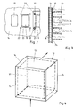
- FIG 4 outlines an embodiment of the basin 10 in which the wall 13 formed on all sides as a double wall 14 is.
- the wall 13 is on the top of the Basin 10 formed as a double wall 14, causing convection the first cooling liquid 11 is used particularly well can be.
- the double-sided wall brings Training the pelvis 10 a higher effort in the here Bushings 17, not shown, for the electrical Feed lines 18 of the winding body, also not shown here 8 with himself. So it can be useful to have the wall 13 not as at least on one side surface of the pool 10 Form double wall 14.
- FIG. 5 shows a housing 24 for everyone beyond FIG electrical and electronic shown in Figure 1 Components of the device 1.
- This housing is up on Bushings 25 for the supply and discharge of the alternating current and bushings 26 for the pipe system 15 of the second Cooling liquid 16 formed closed. So everyone will Pollution of the electrical and electronic components the device 1 avoided.
- Such a housing can also the embodiment of the device 1 according to Figure 1 provided his.
- Above the housing 24 there is an air-permeable one Compartment 27 provided in which the cooler 29 for the cooling liquid 16 acting air blower 28 is arranged. That is, the cooling liquid 16 with the ambient air Device 1 cooled. If the device 1 according to FIG is arranged in a closed room, the room air in as a rule in addition, for example by air conditioning, be cooled.
Abstract
Description
Die Erfindung bezieht sich auf eine Vorrichtung zur unterbrechungsfreien Stromversorgung, wobei die Vorrichtung zwischen eine Wechsel- oder Drehstromquelle, deren Unterbrechungen zu überbrücken sind, und einen oder mehrere mit Wechsel- oder Drehstrom zu versorgende(n) Verbraucher zu schalten ist, mit mindestens einem Gleichrichter für den ankommenden Wechselstrom, mit Akkumulatoren für das Zwischenspeichern elektrischer Energie, mit mindestens einem Wechselrichter für die Batteriespannung der Akkumulatoren und mit einer Steuerelektronik, wobei elektrische Wickelkörper, insbesondere Spulen und Drosseln, und elektronische Halbleiterbausteine vorgesehen sind, die von einem Leistungsstrom durchflossen werden.The invention relates to a device for uninterrupted Power supply, the device between an AC or three-phase source whose interruptions too are bridged, and one or more with exchange or Three-phase consumer (s) to be switched, with at least one rectifier for the incoming alternating current, with accumulators for the temporary storage of electrical Energy, with at least one inverter for the battery voltage the accumulators and with control electronics, where electric bobbins, in particular coils and chokes, and Electronic semiconductor modules are provided, which are Power flow can be flowed through.
Vorrichtungen zur unterbrechungsfreien Stromversorgung, die Unterbrechungen einer Wechsel- oder Drehstromquelle mit Hilfe von in Akkumulatoren gespeicherter elektrischer Energie überbrücken, werden auch als statische USV's (USV = unterbrechungsfreie Stromversorgung) bezeichnet.Uninterruptible power supply devices which Interruptions of an AC or three-phase source with the help bridge electrical energy stored in accumulators, are also called static UPSs (UPS = uninterruptible Power supply).
Die von einem Leistungsstrom durchflossenen elektrischen Wickelkörper und elektronischen Halbleiterbausteine einer USV müssen gekühlt werden. Die Verlustleistungen dieser Bauteile sind auch bei relativ hohen Wirkungsgraden der USV's von typischerweise 95 bis 97 % absolut gesehen so groß, daß sie sich ohne eine Kühlung sehr schnell bis zur Selbstzerstörung aufheizen würden. Die durch die Wickelkörper und die Halbleiterbausteine aufgeheizte Luft muß typischerweise durch eine Klimaanlage wieder abgekühlt werden, da sich eine USV häufig in abgeschlossenen Räumen befindet, die sonst ihrerseits unkontrolliert aufgeheizt würden. The electrical winding bodies through which a power current flows and electronic semiconductor components of a UPS be cooled. The power losses of these components are also with a relatively high efficiency of the UPS of typically 95 up to 97% in absolute terms so large that they are without cooling would heat up very quickly until self-destruction. The heated by the winding body and the semiconductor components Air typically has to be cooled again by an air conditioning system because a UPS is often located in enclosed spaces located, which would otherwise be heated in an uncontrolled manner.
Eine Vorrichtung zur unterbrechungsfreien Stromversorgung der eingangs beschriebenen Art ist aus der US 5 801 937 bekannt. Dort ist auch beschrieben, daß nicht der gesamte Leistungsstrom zu dem Verbraucher hin über die Gleich- und Wechselrichter fließen muß, sondern teilweise auch an diesen vorbeigeführt werden kann. Weiterhin wird eine Flüssigkeitskühlung für Halbleiterbausteine, beispielsweise von Festkörperschaltern in Form sogenannter MOSFET's oder IGBT's vorgeschlagen. Die Kühlung dient dazu, die thermische Anregung der Halbleiterbausteine sehr stark zu reduzieren. Entsprechend sollen als Kühlflüssigkeiten Kryoflüssigkeiten oder flüssiger Stickstoff verwendet werden. Der hierzu erforderliche technische Aufwand ist erheblich.A device for the uninterruptible power supply of the The type described at the outset is known from US Pat. No. 5,801,937. It also describes that not the entire power flow to the consumer via the rectifiers and inverters must flow, but sometimes also led past this can be. Furthermore, liquid cooling for semiconductor devices, for example, solid-state switches in the form So-called MOSFETs or IGBTs proposed. The cooling serves the thermal excitation of the semiconductor devices very much greatly reduce. Accordingly, as cooling liquids Cryogenic liquids or liquid nitrogen can be used. The technical effort required for this is considerable.
Aus der FR 13 577 702 ist es bekannt, einen Trafo in einer
ersten Kühlflüssigkeit anzuordnen, während zugehörige Dioden in
thermischem Kontakt mit einer zweiten Kühlflüssigkeit stehen.
Die Kühlflüssigkeiten sind durch eine Gehäusewandung räumlich
voneinander getrennt, die aber einen Wärmeübergang zuläßt. In
einem jeweils eigenen Leitungssystem mit einer separaten Pumpe
und einem separaten Kühler werden die Kühl flüssigkeiten
umgepumpt, bei denen es sich jeweils um Öl handelt. Dabei
besteht die grundsätzliche Gefahr von Verunreinigungen der
ersten Kühlflüssigkeit, in der sich der Trafo befindet.From
Aus dem Transformatorenbau ist es bekannt, elektrische Wickelkörper, die von einem Leistungsstrom durchflossen werden, in eine Kühlflüssigkeit einzutauchen. Hierfür sind spezielle hochisolierende Kühlflüssigkeiten bekannt. Die Kühlflüssigkeiten reichen dabei an Wärmeaustauschflächen heran, über die sie die aufgenommene Wärme an die Umgebungsluft abgeben. Die Kühlflüssigkeiten können zur Verbesserung ihres Wirkungsgrads auch umgepumpt werden.From the construction of transformers it is known to use electrical winding bodies, through which a power current flows, in to immerse a coolant. For this there are special highly insulating Coolants known. The coolants reach up to the heat exchange surfaces over which they Release the absorbed heat into the ambient air. The coolants can also improve their efficiency be pumped around.
Der Erfindung liegt die Aufgabe zugrunde, eine Vorrichtung der Eingangs beschriebenen Art aufzuzeigen, die eine zuverlässige Kühlung der Wickelkörper und der Halbleiterbausteine, die von einem Leistungsstrom durchflossen werden, auch über sehr große Zeiträume hinweg sicherstellt. Die neue Vorrichtung soll in besonderer Weise dazu geeignet sein, in verschiedene Gesamtkühlkonzepte integriert zu werden.The invention has for its object a device To demonstrate the type described above, which is a reliable Cooling of the winding bodies and the semiconductor components by flow through a power current, even over very large ones Ensures periods of time. The new device is said to be particularly suitable in different overall cooling concepts to be integrated.
Erfindungsgemäß wird diese Aufgabe durch die Merkmale des Anspruchs 1 gelöst.According to the invention, this object is achieved through the features of Claim 1 solved.
Die neue Vorrichtung zur unterbrechungsfreien Stromversorgung weist eine Flüssigkeitskühlung für die von einem Leistungsstrom durchflossenen Wickelkörper und Halbleiterbausteine auf. Hiermit ist bereits der grundsätzliche Vorteil verbunden, daß keine Kühlluft von außen durch die Vorrichtung hindurchgeführt werden muß, die zum Aufbau von Verschmutzungen führen kann, die unter den in einer typischen USV auftretenden hohen Spannungen langfristig die Ursache von Durchschlägen und Kurzschlüssen sein können. Bei der neuen Vorrichtung zur unterbrechungsfreien Stromversorgung ist für die Wickelkörper eine erste Kühlflüssigkeit vorgesehen, die sich nur in einem Becken befindet. Dies ist von Vorteil, weil diese Flüssigkeit besondere isolierende Eigenschaften aufweisen muß, die sie für ein stetiges Umpumpen in einem größeren Leitungssystem mit der damit verbundenen Verschmutzungsgefahr ungeeignet machen. Außerdem sind derartige Flüssigkeiten in aller Regel umweltgefährdend, auch wenn es sich heutzutage nicht mehr unbedingt um PCB-enthaltende Stoffe handeln muß. Die zweite Kühlflüssigkeit, die der ersten Kühlflüssigkeit die in dem Becken von den Wickelkörpern aufgenommene Wärme wieder entzieht und die auch die Halbleiterbausteine kühlt, muß keine besonderen elektrischen Anforderungen erfüllen. Ihre Auswahl ist damit weniger kritisch. Ebenso wird sie durch gewisse Verunreinigungen nicht so bald ihrer Funktionsfähigkeit beraubt. Die Kühlung der Wickelkörper ist sichergestellt, weil sie in die erste Kühlflüssigkeit eingetaucht sind und damit über alle ihre Oberflächen Wärme abgeführt werden kann. Die ausreichende Kühlung der Halbleiterbausteine wird durch ihre direkte Anbindung an das Leitungssystem für die grundsätzlich kältere zweite Kühlflüssigkeit sichergestellt.The new device for uninterruptible power supply has liquid cooling for by a power stream flowed through winding body and semiconductor devices. Herewith there is already the fundamental advantage that none Cooling air can be passed through the device from the outside must, which can lead to the build-up of dirt under the high voltages that occur in a typical UPS in the long term the cause of breakdowns and short circuits can. With the new device for uninterrupted Power supply is a first cooling liquid for the winding body provided that is located only in a pool. This is advantageous because this liquid has special insulating properties must have, which they for a constant pumping in a larger pipe system with the associated risk of contamination make unsuitable. In addition, there are Liquids are generally environmentally hazardous, even if they are nowadays not necessarily around PCB-containing substances must act. The second coolant, that of the first coolant the one taken up in the pool by the winding bodies Extracts heat again and that also removes the semiconductor components cools, does not have to meet any special electrical requirements. Your selection is therefore less critical. Likewise, it is through certain contaminants do not function as soon robbed. The cooling of the winding body is ensured because they are immersed in the first coolant and thus over all of their surfaces can be dissipated heat. The sufficient Cooling of the semiconductor components is done by their direct Connection to the pipe system for the generally colder second coolant ensured.
In der bevorzugten Ausführungsform der neuen Vorrichtung ist das Becken für die erste Kühlflüssigkeit zumindest partiell mit einer Doppelwandung ausgebildet, wobei die Doppelwandung Teil des Leitungssystems für die zweite Kühlflüssigkeit ist und wobei die Halbleiterbausteine an dem äußeren Teil der Doppelwandung angeordnet sind. Zumindest in dem doppelwandigen Bereich des Beckens wird verhindert, daß irgendwelche Wärme aus dem Inneren des Beckens über die Wandung direkt auf weitere Bauteile der Vorrichtung zur unterbrechungsfreien Stromversorgung übertragen wird. Die Erwärmung der Wickelkörper wird damit von allen weiteren Bestandteilen der USV im wesentlichen abgeschirmt. Für die Halbleiterbausteine ist der äußere Teil der Doppelwandung als Montageort besonders gut geeignet, weil hier viel Platz mit einer guten Anbindung an das Leitungssystem für die zweite Kühlflüssigkeit zur Verfügung steht.In the preferred embodiment of the new device this is Basin for the first coolant at least partially formed a double wall, the double wall part of the line system for the second cooling liquid and where the semiconductor components on the outer part of the double wall are arranged. At least in the double-walled area of the Basin prevents any heat from inside the basin over the wall directly to other components of the Transfer device for uninterruptible power supply becomes. The heating of the winding body is thus everyone other components of the UPS are essentially shielded. For the semiconductor device is the outer part of the double wall Particularly well suited as an installation location because there is plenty of space here a good connection to the line system for the second Coolant is available.
Der innere Teil der Doppelwandung kann mit Wärmeaustauschflächenvergrößerungen, insbesondere in Form von in die erst Kühlflüssigkeit hineinragenden Rippen versehen sein. Hierdurch wird die pro Zeiteinheit bei einer festen Temperaturdifferenz zwischen den beiden Kühlflüssigkeiten übertragbare Wärmemenge gesteigert. Eine weitere Steigerungsmöglichkeit besteht darin, zumindest die zweite Kühlflüssigkeit im Bereich der Wärmeaustauschflächen stark umzuwälzen oder gar in Turbulenz zu versetzen. Eine Umwälzung der ersten Kühlflüssigkeit kann jedoch nachteilig für die Standzeit der ersten Kühlflüssigkeit sein, wenn es hierdurch potentiell zu Verunreinigungen der ersten Kühlflüssigkeit kommt.The inner part of the double wall can be enlarged with heat exchange surfaces, especially in the form of in the first Ribs protruding coolant. Hereby is the per time unit at a fixed temperature difference Amount of heat that can be transferred between the two cooling liquids increased. Another possibility to increase is at least the second cooling liquid in the area of the heat exchange surfaces to circulate strongly or even to create turbulence. Circulation of the first cooling liquid can, however be disadvantageous for the service life of the first coolant, if this could potentially contaminate the first Coolant comes.
Der äußere Teil der Doppelwandung kann mit Durchbrechungen versehen sein, die unter Zwischenordnung von umlaufenden Dichtungen von den Halbleiterbausteinen verschlossen werden. Dabei bedeutet die Zwischenordnung der Dichtungen, daß sich diese im Randbereich der Durchbrechungen zwischen dem äußeren Teil der Doppelwandung und dem rückwärtigen Teil der Halbleiterbausteine befinden. So reicht die zweite Kühlflüssigkeit unmittelbar an die Halbleiterbausteine heran, wodurch die Effektivität deren Kühlung gesteigert wird.The outer part of the double wall can have openings be provided with the interposition of circulating Seals are sealed by the semiconductor components. The intermediate arrangement of the seals means that this in the edge area of the openings between the outer Part of the double wall and the rear part of the semiconductor components are located. So the second coolant is enough directly to the semiconductor devices, which the Effectiveness whose cooling is increased.
Um Verunreinigungen der ersten Kühlflüssigkeit zu vermeiden, ist das Becken allseitig geschlossen auszubilden. Um dabei thermischen Ausdehnungen der ersten Kühlflüssigkeit Rechnung zu tragen, muß irgendein Druckausgleichsmittel vorgesehen sein. Ein solches Druckausgleichsmittel kann beispielsweise ein komprimierbares Gasvolumen aufweisen. Bei ausreichender Größe des Gasvolumens führt weder eine Temperatursteigerung noch seine Kompression zu einer nennenswerten Drucksteigerung in dem geschlossenen Becken.To avoid contamination of the first coolant design the pool to be closed on all sides. To do thermal Expansions of the first coolant any pressure compensation device must be provided. On such pressure compensation means can be, for example, a compressible one Have gas volume. If the size of the Gas volume does not lead to an increase in temperature or its Compression to a significant increase in pressure in the closed basin.
Um jegliche Verunreinigungen der neuen Vorrichtung von außen zu verhindern, kann ein geschlossenes Gehäuse für alle elektronischen und elektrischen Bestandteile der Vorrichtung vorgesehen sein, aus dem bzw. in das nur Stromleitungen und Leitungen für die zweite Kühlflüssigkeit heraus- bzw. hereinführen.To prevent any contamination of the new device from the outside can prevent a closed housing for all electronic and electrical components of the device are provided be from or into which only power lines and lines for lead the second coolant out or in.
Um der zweiten Kühlflüssigkeit Wärme zu entziehen, kann ein Wärmetauscher vorgesehen sein. Dieser Wärmetauscher kann in einem Bereich der Vorrichtung angeordnet sein, der an das geschlossene Gehäuse für alle elektrischen und elektronischen Bestandteile der Vorrichtung angrenzt. Es ist aber auch möglich, den Wärmetauscher weiter entfernt von den restlichen Bestandteilen der Vorrichtung anzuordnen, beispielsweise bei einer in einem Kellerraum angeordneten USV irgendwo im Freien. Dies bietet sich insbesondere an, wenn der Wärmetauscher als Kühler mit einem Luftgebläse ausgebildet ist. Grundsätzlich kann ein solcher Kühler mit einem Luftgebläse aber auch direkt an die restlichen Bestandteile der Vorrichtung angebaut sein.To extract heat from the second coolant, a Heat exchangers may be provided. This heat exchanger can be in a region of the device may be arranged which is connected to the closed housing for all electrical and electronic Components of the device are adjacent. But it is also possible the heat exchanger further away from the remaining components to arrange the device, for example in a a UPS located somewhere outdoors. This is particularly useful when the heat exchanger is used as a cooler is formed with an air blower. Basically, one such cooler with an air blower but also directly to the remaining components of the device can be grown.
Bei dem Wärmetauscher für die zweite Kühlflüssigkeit kann es sich um eine Flüssig-Flüssig-Wärmetauscher mit einer dritten Kühlflüssigkeit handeln. Ein solcher Wärmetauscher ist vorzugsweise in einem an das geschlossene Gehäuse für alle elektronischen und elektrischen Bestandteile der Vorrichtung angrenzenden Abteil der Vorrichtung untergebracht. Die dritte Kühlflüssigkeit kann an einem geeigneten Ort in einem Kühler mit Umgebungsluft gekühlt werden. Bei der dritten Kühlflüssigkeit kann es sich auch um den Wasserkreislauf einer zentralen Klimaanlage handeln.The heat exchanger for the second coolant can a liquid-liquid heat exchanger with a third Act coolant. Such a heat exchanger is preferred in one to the closed housing for all electronic and electrical components of the device adjacent Compartment of the device housed. The third coolant can be in a suitable place in a cooler Ambient air to be cooled. The third coolant it can also be a central water cycle Act air conditioning.
Während die erste Kühlflüssigkeit vorzugsweise eine aus dem Transformatorenbau bekannte Kühlflüssigkeit mit hoher Isolationswirkung ist, kann die zweite Kühlflüssigkeit einfaches Wasser sein, dem korrosionshindernde Zusätze zugegeben sein können.While the first coolant is preferably one from the Transformer construction known coolant with a high insulation effect is, the second coolant can be simple Be water to which corrosion-preventing additives have been added can.
Die Erfindung wird im folgenden anhand von Ausführungsbeispielen näher erläutert und beschrieben. Dabei sind in den beigefügten Zeichnungen die verschiedenen Ausführungsformen in Form von Prinzipschaubildern wiedergegeben. Die elektrischen und elektronischen Details von USV's sind dem Fachmann bekannt. Auf sie wird hier nicht näher eingegangen werden. In den Zeichnungen zeigt
- Figur 1
- die für die Erfindung wesentlichen Bestandteile der neuen Vorrichtung zur unterbrechungsfreien Stromversorgung in einer ersten Ausführungsform,
Figur 2- ein erstes Detail eines Beckens für eine erste Kühlflüssigkeit bei der Vorrichtung zur unterbrechungsfreien Stromversorgung gemäß Figur 1,
Figur 3- ein zweites Detail des Beckens,
Figur 4- eine abgewandelte Ausführungsform des Beckens,
Figur 5- die neue Vorrichtung zur unterbrechungsfreien Stromversorgung in einer gegenüber Figur 1 weiterentwickelten Ausführungsform und
Figur 6- die Vorrichtung zur unterbrechungsfreien Stromversorgung in einer gegenüber Figur 5 alternativen Ausführungsform.
- Figure 1
- the components of the new device for uninterruptible power supply essential for the invention in a first embodiment,
- Figure 2
- 1 shows a first detail of a basin for a first cooling liquid in the device for uninterruptible power supply according to FIG. 1,
- Figure 3
- a second detail of the pelvis,
- Figure 4
- a modified embodiment of the basin,
- Figure 5
- the new device for uninterruptible power supply in an embodiment compared to Figure 1 and
- Figure 6
- the device for uninterruptible power supply in an alternative to Figure 5 embodiment.
Figur 1 zeigt eine Vorrichtung 1, die zur unterbrechungsfreien
Stromversorgung dient. Ein von einer Wechselstromquelle 2
kommender Wechselstrom, der durch einen Pfeil 3 angedeutet ist,
wird in der Vorrichtung 1 gleichgerichtet. Die gleichgerichtete
Spannung wird an Akkumulatoren 4 angelegt. Die Batteriespannung
der Akkumulatoren wird wieder wechselgerichtet und der als Pfeil
5 angedeutete Ausgangswechselstrom gelangt zu einem Verbraucher
6. Die Gleich- und Wechselrichter der Vorrichtung 1 sowie eine
zugehörige Steuerelektronik, die beispielsweise auch dafür
sorgen kann, daß nur ein Teil des ankommenden Wechselstroms
gleich- und wieder wechselgerichtet wird, umfaßt neben anderen
elektrischen und elektronischen Bestandteilen 7 verschiedene
elektrische Wickelkörper 8 und verschiedene elektronische
Halbleiterbausteine 9, die jeweils von einem Leistungsstrom
durchflossen werden. Die dabei anfallende Verlustwärme muß
abgeführt werden, um eine Überhitzung der Wickelkörper 8 bzw.
der Halbleiterbausteine 9 zu verhindern, die zu einer Selbstzerstörung
führen würde. Bei den Wickelkörpern 8 kann es sich um
Spulen, Drosseln und Wicklungen von Transformatoren handeln. Die
Halbleiterbausteine 9 können beispielsweise Festkörperschalter
in Form von IGBT's sein. Die Kühlung der Wickelkörper 8 und der
Halbleiterbausteine 9 wird bei der Vorrichtung 1 bewirkt, indem
die Wickelkörper 8 in einem geschlossenen Becken 10 angeordnet
sind, das mit einer ersten Kühlflüssigkeit 11 befüllt ist.
Thermische Ausdehnungen der ersten Kühlflüssigkeit 11 werden
durch einen gasbefüllten Ballon 12 ausgeglichen. Die Wandung 13
des Beckens 10 ist zumindest partiell als Doppelwandung 14
ausgebildet, wobei die Doppelwandung 14 Teil eines Leitungssystems
15 für eine zweite Kühlflüssigkeit 16 ist. Während die
erste Kühlflüssigkeit 11 besondere isolierende Eigenschaften
aufweist, handelt es sich bei der zweiten Kühlflüssigkeit 16 um
Wasser. Die Wandung 13 ist gegenüber den Wickelkörpern 8
isoliert. Hierzu sind isolierende Durchführungen 17 für die
elektrischen Zu- und Ableitungen 18 zu den Wickelkörpern 8
vorgesehen. Die zweite Kühlflüssigkeit 16 dient über Wärmeaustauschflächen
34 gleichzeitig zur Kühlung der ersten Kühlflüssigkeit
11 und der Halbleiterbausteine 9, die in einem
Bereich der Doppelwandung 14 an deren äußeren Teil angeordnet
sind. Durch die erste Kühlflüssigkeit 11 sind die Wickelkörper
8 vor äußeren Verunreinigungen geschützt. Das Becken 10 schützt
die erste Kühlflüssigkeit 11 ihrerseits vor Verunreinigungen.
Die Halbleiterbausteine 9 sind weniger verunreingungsempflindlich
und sind allein schon deshalb geschützt, weil sie nicht wie
sonst üblich ständig von Kühlluft umströmt werden, die sich
potentiell ablagernde Verunreinigung mit sich führt. Eine Pumpe
30 ist zum Umpumpen der zweiten Kühlflüssigkeit 16 durch einen
Kühler 29 vorgesehen, der von einem Luftgebläse 28 mit Luft
beeaufschlagt wird. Der Kühler 29 kann wie angedeutet entfernt
von der restlichen Vorrichtung 1 angeordnet sein. Wenn die Vorrichtung
beispielsweise in einem inneren Kellerraum steht, ist
der Kühler 29 vorzugsweise irgendwo im Außenbereich angeordnet.Figure 1 shows a device 1 which is used for uninterrupted
Power supply is used. One from an
Die Anordnung der Halbleiterbausteine 9 an dem äußeren Teil der
Doppelwandung 14 geht näher aus Figur 2 hervor. In dem äußeren
Teil der Doppelwandung 14 sind Durchbrechungen 19 vorgesehen. Um
diese Durchbrechungen 19 herum sind ringförmige Dichtungen 20
angeordnet. Über die Dichtungen 20 sind die Halbleiterbausteine
9 an die Doppelwandung 4 angedrückt. Dabei wird eine Andrückkraft
durch Muttern 21 aufgebracht, die auf an die Doppelwandung
14 angeschweißte Gewindestangen 22 aufgeschraubt sind. In Figur
2 ist im linken Teil nur die reine Durchbrechung 19, in der
Mitte die Durchbrechung 19 mit der Dichtung 20 und den Gewindestangen
22 und rechts ein Teil eines die Durchbrechung 19 unter
Zwischenordnung der Dichtung 20 und unter Befestigung mit den
Muttern 21 abdichtenden Halbleiterbausteins 9 wiedergegeben.The arrangement of the
Figur 3 zeigt die Anordnung von Rippen 23 an der Seite des inneren
Teils der Doppelwandung 14, der der ersten Kühlflüssigkeit
zugewandt ist. Die Rippen 23 ragen in die erste Kühlflüssigkeit
11 hinein und vergrößern die Wärmeaustauschflächen 34 von der
ersten Kühlflüssigkeit 11 auf den inneren Teil der Doppelwandung
14 und damit zwischen der ersten Kühlflüssigkeit 11 und der
zweiten Kühlflüssigkeit 16. Weitere Rippen 35 können von der
Doppelwandung in die zweite Kühlflüssigkeit 16 hineinragen, um
auch hier die Wärmeaustauschflächen zu vergrößern. Der absolute
Wärmeübertrag auf die zweite Kühlflüssigkeit 16 kann aber auch
durch deren Umpumpen verbessert werden.Figure 3 shows the arrangement of
Figur 4 skizziert eine Ausführungsform des Beckens 10, in der
dessen Wandung 13 allseitig als Doppelwandung 14 ausgebildet
ist. Insbesondere ist die Wandung 13 an der Oberseite des
Beckens 10 als Doppelwandung 14 ausgebildet, wodurch Konvektionen
der ersten Kühlflüssigkeit 11 besonders gut ausgenutzt
werden können. Allerdings bringt die allseitig doppelwandige
Ausbildung des Beckens 10 einen höheren Aufwand bei den hier
nicht dargestellten Durchführungen 17 für die elektrischen
Zuleitungen 18 der hier ebenfalls nicht dargestellten Wickelkörper
8 mit sich. So kann es sinnvoll sein, die Wandung 13
zumindest an einer Seitenfläche des Beckens 10 nicht als
Doppelwandung 14 auszubilden.Figure 4 outlines an embodiment of the
Figur 5 zeigt über Figur 1 hinausgehend ein Gehäuse 24 für alle
in Figur 1 dargestellten elektrischen und elektronischen
Bestandteile der Vorrichtung 1. Dieses Gehäuse ist bis auf
Durchführungen 25 für die Zufuhr und Abfuhr des Wechselstroms
und Durchführungen 26 für das Leitungssystem 15 der zweiten
Kühlflüssigkeit 16 geschlossen ausgebildet. So wird jede
Verschmutzung der elektrischen und elektronischen Bestandteile
der Vorrichtung 1 vermieden. Ein solches Gehäuse kann auch bei
der Ausführungsform der Vorrichtung 1 gemäß Figur 1 vorgesehen
sein. Oberhalb des Gehäuses 24 ist hier ein luftdurchlässiges
Abteil 27 vorgesehen, in dem das den Kühler 29 für die Kühlflüssigkeit
16 beaufschlagende Luftgebläse 28 angeordnet ist.
Das heißt, die Kühlflüssigkeit 16 wird mit Umgebungsluft der
Vorrichtung 1 gekühlt. Wenn die Vorrichtung 1 gemäß Figur 5 in
einem geschlossenen Raum angeordnet wird, muß die Raumluft in
aller Regel zusätzlich, beispielsweise durch eine Klimaanlage,
gekühlt werden.FIG. 5 shows a
Eine unmittelbare Abfuhr der Wärme aus einem solchen Raum ist
wieder bei der Ausführungsform der Vorrichtung 1 gemäß Figur 6
gegeben. Hier ist in dem oberen Abteil 27, das hier nicht
luftdurchlässig sein muß, ein Flüssig-Flüssig-Wärmetauscher 31
vorgesehen, indem der zweiten Kühlflüssigkeit 16 die Wärme durch
eine dritte Kühlflüssigkeit 32 entzogen wird, die in einem Leitungssystem
33 zirkuliert. Das Leitungssystem 33 kann zu einem
externen luftgekühlten Kühler führen. Es kann sich auch um das
Leitungssystem einer zentralen Klimaanlage handeln, wie sie in
vielen Großgebäuden vorhanden ist. Insbesondere in diesem Fall
und entsprechenden Fällen macht die Verwendung einer im
Vergleich zu der Ausführungsform gemäß Figur 1 zusätzlichen
Kühlflüssigkeit Sinn, um das zentrale Leitungssystem von dem
durch das Gehäuse 24 führenden Leitungssystem aus Sicherheitsgründen
zu trennen. Auffällig ist, daß der Aufbau der Vorrichtung
1 innerhalb des Gehäuses 24 in beiden Ausführungsformen
gemäß den Figuren 5 und 6 vollständig identisch ist. Auch bei
der Ausführungsform der Vorrichtung 1 gemäß Figur 1 kann dieser
Aufbau verwirklicht werden, so daß eine universelle Baueinheit
die verschiedenen Einsatzvarianten abdeckt. There is an immediate dissipation of heat from such a room
again in the embodiment of the device 1 according to FIG. 6
given. Here is in the
- 1 -1 -
- Vorrichtung (USV)Device (UPS)
- 2 -2 -
- StromquellePower source
- 3 -3 -
- Pfeilarrow
- 4 -4 -
- Akkumulatoraccumulator
- 5 -5 -
- Pfeilarrow
- 6 -6 -
- Verbraucherconsumer
- 7 -7 -
- Bestandteilcomponent
- 8 -8th -
- WickelkörperBobbin
- 9 -9 -
- HalbleiterbausteinSemiconductor device
- 10 -10 -
- Beckenpool
- 11 -11 -
- erste Kühlflüssigkeitfirst coolant
- 12 -12 -
- Ballonballoon
- 13 -13 -
- WandungWall
- 14 -14 -
- DoppelwandungDouble wall
- 15 -15 -
- LeitungssystemPipe system
- 16 -16 -
- zweite Kühlflüssigkeitsecond coolant
- 17 -17 -
- Durchführungexecution
- 18 -18 -
- Leitungmanagement
- 19 -19 -
- DurchbrechungBreakthrough
- 20 -20 -
- Dichtungpoetry
- 21 -21 -
- Muttermother
- 22 -22 -
- GewindestangeThreaded rod
- 23 -23 -
- Ripperib
- 24 -24 -
- Gehäusecasing
- 25 -25 -
- Durchführungexecution
- 26 -26 -
- Durchführungexecution
- 27 -27 -
- Abteilcompartment
- 28 -28 -
- LuftgebläseAir blower
- 29 -29 -
- Kühlercooler
- 30 -30 -
- Pumpepump
- 31 -31 -
- WärmetauscherHeat exchanger
- 32 -32 -
- dritte Kühlflüssigkeitthird coolant
- 33 -33 -
- LeitungssystemPipe system
- 34 -34 -
- WärmeaustauschflächeHeat exchange surface
- 35 -35 -
- Ripperib
Claims (10)
Applications Claiming Priority (2)
| Application Number | Priority Date | Filing Date | Title |
|---|---|---|---|
| DE19852125 | 1998-11-12 | ||
| DE19852125A DE19852125C1 (en) | 1998-11-12 | 1998-11-12 | Back-up current supply for electrical load has electrical coils contained within cooling fluid bath and second cooling fluid passed between heat exchange surfaces for cooling fluid bath and power semiconductors |
Publications (3)
| Publication Number | Publication Date |
|---|---|
| EP1001671A2 true EP1001671A2 (en) | 2000-05-17 |
| EP1001671A3 EP1001671A3 (en) | 2001-01-03 |
| EP1001671B1 EP1001671B1 (en) | 2005-01-19 |
Family
ID=7887512
Family Applications (1)
| Application Number | Title | Priority Date | Filing Date |
|---|---|---|---|
| EP99121365A Expired - Lifetime EP1001671B1 (en) | 1998-11-12 | 1999-10-27 | Device for uninterruptible power supply |
Country Status (3)
| Country | Link |
|---|---|
| EP (1) | EP1001671B1 (en) |
| AT (1) | ATE287631T1 (en) |
| DE (2) | DE19852125C1 (en) |
Families Citing this family (10)
| Publication number | Priority date | Publication date | Assignee | Title |
|---|---|---|---|---|
| DE102004004624B3 (en) * | 2004-01-29 | 2005-07-28 | Siemens Ag | Submarine fuel cell device, for retro-fitting, has switchboard in the same segment and at least one fuel cell control board with automatic safety system |
| ITPD20060006A1 (en) * | 2006-01-05 | 2007-07-06 | Liebert Hiross Spa | UPS' |
| US8011421B2 (en) * | 2006-12-12 | 2011-09-06 | Honeywell International Inc. | System and method that dissipate heat from an electronic device |
| DE102007003941B3 (en) * | 2007-01-23 | 2008-06-19 | Meuleman, André | Power transformer has compression-proof boiler and container-integrated cooling system, in which corrugated sheet walls or radiators are arranged on both sides of boiler or container wall at boiler or container |
| DE102009010256A1 (en) * | 2009-02-24 | 2010-08-26 | Jungheinrich Aktiengesellschaft | Printed circuit board with heat sink |
| ITBO20090684A1 (en) * | 2009-10-22 | 2011-04-23 | Stilrossi S A S Di Lino Rossi & C Servizi Per | UPS' |
| DE102011076986A1 (en) * | 2011-06-06 | 2012-12-06 | Schneider Electric Sachsenwerk Gmbh | Cooling device for a switchgear for an electrical power supply network and such a switchgear |
| EP3367768A1 (en) | 2017-02-28 | 2018-08-29 | Piller Group GmbH | Online ups installation with combined air and water cooling |
| PL3917300T3 (en) | 2020-05-29 | 2023-03-06 | Ovh | Uninterruptible power supply having a liquid cooling device |
| PL3917299T3 (en) | 2020-05-29 | 2023-12-04 | Ovh | Uninterruptible power supply having a liquid cooling device |
Citations (5)
| Publication number | Priority date | Publication date | Assignee | Title |
|---|---|---|---|---|
| FR1357702A (en) * | 1963-02-25 | 1964-04-10 | Comp Generale Electricite | Advanced Straightener Set |
| US3596711A (en) * | 1968-06-28 | 1971-08-03 | Licentia Gmbh | Cooling apparatus |
| US3851221A (en) * | 1972-11-30 | 1974-11-26 | P Beaulieu | Integrated circuit package |
| US4449580A (en) * | 1981-06-30 | 1984-05-22 | International Business Machines Corporation | Vertical wall elevated pressure heat dissipation system |
| US5801937A (en) * | 1996-10-16 | 1998-09-01 | American Superconductor Corporation | Uninterruptible power supplies having cooled components |
Family Cites Families (1)
| Publication number | Priority date | Publication date | Assignee | Title |
|---|---|---|---|---|
| DE2027621A1 (en) * | 1970-06-05 | 1971-12-09 | Transformatoren Union Ag | Device for cooling electronic devices |
-
1998
- 1998-11-12 DE DE19852125A patent/DE19852125C1/en not_active Expired - Fee Related
-
1999
- 1999-10-27 EP EP99121365A patent/EP1001671B1/en not_active Expired - Lifetime
- 1999-10-27 DE DE59911479T patent/DE59911479D1/en not_active Expired - Lifetime
- 1999-10-27 AT AT99121365T patent/ATE287631T1/en active
Patent Citations (5)
| Publication number | Priority date | Publication date | Assignee | Title |
|---|---|---|---|---|
| FR1357702A (en) * | 1963-02-25 | 1964-04-10 | Comp Generale Electricite | Advanced Straightener Set |
| US3596711A (en) * | 1968-06-28 | 1971-08-03 | Licentia Gmbh | Cooling apparatus |
| US3851221A (en) * | 1972-11-30 | 1974-11-26 | P Beaulieu | Integrated circuit package |
| US4449580A (en) * | 1981-06-30 | 1984-05-22 | International Business Machines Corporation | Vertical wall elevated pressure heat dissipation system |
| US5801937A (en) * | 1996-10-16 | 1998-09-01 | American Superconductor Corporation | Uninterruptible power supplies having cooled components |
Also Published As
| Publication number | Publication date |
|---|---|
| ATE287631T1 (en) | 2005-02-15 |
| EP1001671B1 (en) | 2005-01-19 |
| DE19852125C1 (en) | 2000-04-20 |
| DE59911479D1 (en) | 2005-02-24 |
| EP1001671A3 (en) | 2001-01-03 |
Similar Documents
| Publication | Publication Date | Title |
|---|---|---|
| RU2412523C2 (en) | Design system for modular power cells | |
| EP1848260B1 (en) | Inverter | |
| DE69916038T2 (en) | METHOD AND DEVICE FOR COOLING A TRANSFORMER | |
| EP1001671B1 (en) | Device for uninterruptible power supply | |
| DE102013100607A1 (en) | Inverter with two-part housing | |
| EP3428000A1 (en) | Device for charging at least one battery | |
| DE102019216970A1 (en) | Stationary induction charging station | |
| EP3590315B1 (en) | Online ups installation with combined air and water cooling | |
| EP2567424A1 (en) | Electrical energy store and cooling device | |
| DE212016000296U1 (en) | power converters | |
| EP3401956A1 (en) | Power semiconductor module for a motor vehicle and motor vehicle | |
| DE19545448A1 (en) | Multi-function housing for static converter of motor vehicle | |
| DE19815645C1 (en) | Electronic converter arrangement with cooling system | |
| DE102018100394A1 (en) | battery module | |
| WO2014131738A1 (en) | Activatable battery module | |
| DE102020205236A1 (en) | Power converter | |
| DE102004054060B3 (en) | Energy storage for e.g. streetcar, has sets of double-layer capacitors forming modules, respectively, and liquid medium as cooling medium, where liquid medium flows through modules and removes heat that is produced in modules | |
| DE3309724C2 (en) | ||
| DE102004030457A1 (en) | Inverter for currents, e.g. for converting direct/alternating current voltages, has a casing with a cooling unit for cooling the electric/electronic components in the inverter | |
| DE102009031370A1 (en) | Cooling device for power converter, has element with material and another element with another material, where latter material has higher heat storage capacity than former material | |
| DE102018204588A1 (en) | Arrangement for cooling components and use of an electrolyte of an electrochemical storage as a coolant in such an arrangement | |
| EP1065782B1 (en) | Device for supplying uninterrupted power with air cooling | |
| DE102004013719A1 (en) | Electrodynamic motor to act as a synchronous, asynchronous or direct current motor, e.g. in a motor vehicle, has electric power of 20 kilowatts and more | |
| DE102020105788A1 (en) | Cooling concept for direct fluid cooling of vertically installed electrical machines using a phase change material (PCM) | |
| DE10147094A1 (en) | Cooling device with magnetic thermal fluid |
Legal Events
| Date | Code | Title | Description |
|---|---|---|---|
| PUAI | Public reference made under article 153(3) epc to a published international application that has entered the european phase |
Free format text: ORIGINAL CODE: 0009012 |
|
| AK | Designated contracting states |
Kind code of ref document: A2 Designated state(s): AT BE CH CY DE DK ES FI FR GB GR IE IT LI LU MC NL PT SE |
|
| AX | Request for extension of the european patent |
Free format text: AL;LT;LV;MK;RO;SI |
|
| PUAL | Search report despatched |
Free format text: ORIGINAL CODE: 0009013 |
|
| AK | Designated contracting states |
Kind code of ref document: A3 Designated state(s): AT BE CH CY DE DK ES FI FR GB GR IE IT LI LU MC NL PT SE |
|
| AX | Request for extension of the european patent |
Free format text: AL;LT;LV;MK;RO;SI |
|
| 17P | Request for examination filed |
Effective date: 20001219 |
|
| AKX | Designation fees paid |
Free format text: AT BE CH CY DE DK ES FI FR GB GR IE IT LI LU MC NL PT SE |
|
| RAP1 | Party data changed (applicant data changed or rights of an application transferred) |
Owner name: RWE PILLER GMBH |
|
| GRAP | Despatch of communication of intention to grant a patent |
Free format text: ORIGINAL CODE: EPIDOSNIGR1 |
|
| GRAS | Grant fee paid |
Free format text: ORIGINAL CODE: EPIDOSNIGR3 |
|
| GRAA | (expected) grant |
Free format text: ORIGINAL CODE: 0009210 |
|
| AK | Designated contracting states |
Kind code of ref document: B1 Designated state(s): AT BE CH CY DE DK ES FI FR GB GR IE IT LI LU MC NL PT SE |
|
| PG25 | Lapsed in a contracting state [announced via postgrant information from national office to epo] |
Ref country code: NL Free format text: LAPSE BECAUSE OF FAILURE TO SUBMIT A TRANSLATION OF THE DESCRIPTION OR TO PAY THE FEE WITHIN THE PRESCRIBED TIME-LIMIT Effective date: 20050119 Ref country code: IT Free format text: LAPSE BECAUSE OF FAILURE TO SUBMIT A TRANSLATION OF THE DESCRIPTION OR TO PAY THE FEE WITHIN THE PRESCRIBED TIME-LIMIT;WARNING: LAPSES OF ITALIAN PATENTS WITH EFFECTIVE DATE BEFORE 2007 MAY HAVE OCCURRED AT ANY TIME BEFORE 2007. THE CORRECT EFFECTIVE DATE MAY BE DIFFERENT FROM THE ONE RECORDED. Effective date: 20050119 Ref country code: FI Free format text: LAPSE BECAUSE OF FAILURE TO SUBMIT A TRANSLATION OF THE DESCRIPTION OR TO PAY THE FEE WITHIN THE PRESCRIBED TIME-LIMIT Effective date: 20050119 |
|
| REG | Reference to a national code |
Ref country code: GB Ref legal event code: FG4D Free format text: NOT ENGLISH |
|
| REG | Reference to a national code |
Ref country code: CH Ref legal event code: EP |
|
| REG | Reference to a national code |
Ref country code: IE Ref legal event code: FG4D Free format text: GERMAN |
|
| REF | Corresponds to: |
Ref document number: 59911479 Country of ref document: DE Date of ref document: 20050224 Kind code of ref document: P |
|
| REG | Reference to a national code |
Ref country code: CH Ref legal event code: NV Representative=s name: RIEDERER HASLER & PARTNER PATENTANWAELTE AG |
|
| PG25 | Lapsed in a contracting state [announced via postgrant information from national office to epo] |
Ref country code: SE Free format text: LAPSE BECAUSE OF FAILURE TO SUBMIT A TRANSLATION OF THE DESCRIPTION OR TO PAY THE FEE WITHIN THE PRESCRIBED TIME-LIMIT Effective date: 20050419 Ref country code: GR Free format text: LAPSE BECAUSE OF FAILURE TO SUBMIT A TRANSLATION OF THE DESCRIPTION OR TO PAY THE FEE WITHIN THE PRESCRIBED TIME-LIMIT Effective date: 20050419 Ref country code: DK Free format text: LAPSE BECAUSE OF FAILURE TO SUBMIT A TRANSLATION OF THE DESCRIPTION OR TO PAY THE FEE WITHIN THE PRESCRIBED TIME-LIMIT Effective date: 20050419 |
|
| PG25 | Lapsed in a contracting state [announced via postgrant information from national office to epo] |
Ref country code: ES Free format text: LAPSE BECAUSE OF FAILURE TO SUBMIT A TRANSLATION OF THE DESCRIPTION OR TO PAY THE FEE WITHIN THE PRESCRIBED TIME-LIMIT Effective date: 20050430 |
|
| GBT | Gb: translation of ep patent filed (gb section 77(6)(a)/1977) |
Effective date: 20050425 |
|
| NLV1 | Nl: lapsed or annulled due to failure to fulfill the requirements of art. 29p and 29m of the patents act | ||
| PG25 | Lapsed in a contracting state [announced via postgrant information from national office to epo] |
Ref country code: CY Free format text: LAPSE BECAUSE OF FAILURE TO SUBMIT A TRANSLATION OF THE DESCRIPTION OR TO PAY THE FEE WITHIN THE PRESCRIBED TIME-LIMIT Effective date: 20051027 |
|
| PG25 | Lapsed in a contracting state [announced via postgrant information from national office to epo] |
Ref country code: MC Free format text: LAPSE BECAUSE OF NON-PAYMENT OF DUE FEES Effective date: 20051031 Ref country code: BE Free format text: LAPSE BECAUSE OF NON-PAYMENT OF DUE FEES Effective date: 20051031 |
|
| PLBE | No opposition filed within time limit |
Free format text: ORIGINAL CODE: 0009261 |
|
| STAA | Information on the status of an ep patent application or granted ep patent |
Free format text: STATUS: NO OPPOSITION FILED WITHIN TIME LIMIT |
|
| ET | Fr: translation filed | ||
| 26N | No opposition filed |
Effective date: 20051020 |
|
| BERE | Be: lapsed |
Owner name: RWE PILLER G.M.B.H. Effective date: 20051031 |
|
| PG25 | Lapsed in a contracting state [announced via postgrant information from national office to epo] |
Ref country code: PT Free format text: LAPSE BECAUSE OF NON-PAYMENT OF DUE FEES Effective date: 20050619 |
|
| REG | Reference to a national code |
Ref country code: FR Ref legal event code: PLFP Year of fee payment: 17 |
|
| REG | Reference to a national code |
Ref country code: FR Ref legal event code: PLFP Year of fee payment: 18 |
|
| REG | Reference to a national code |
Ref country code: FR Ref legal event code: PLFP Year of fee payment: 19 |
|
| REG | Reference to a national code |
Ref country code: FR Ref legal event code: PLFP Year of fee payment: 20 |
|
| PGFP | Annual fee paid to national office [announced via postgrant information from national office to epo] |
Ref country code: LU Payment date: 20181022 Year of fee payment: 20 |
|
| PGFP | Annual fee paid to national office [announced via postgrant information from national office to epo] |
Ref country code: IE Payment date: 20181022 Year of fee payment: 20 Ref country code: DE Payment date: 20180718 Year of fee payment: 20 Ref country code: AT Payment date: 20181019 Year of fee payment: 20 |
|
| PGFP | Annual fee paid to national office [announced via postgrant information from national office to epo] |
Ref country code: CH Payment date: 20181025 Year of fee payment: 20 Ref country code: FR Payment date: 20181023 Year of fee payment: 20 Ref country code: GB Payment date: 20181025 Year of fee payment: 20 |
|
| REG | Reference to a national code |
Ref country code: DE Ref legal event code: R071 Ref document number: 59911479 Country of ref document: DE |
|
| REG | Reference to a national code |
Ref country code: CH Ref legal event code: PL |
|
| REG | Reference to a national code |
Ref country code: GB Ref legal event code: PE20 Expiry date: 20191026 |
|
| REG | Reference to a national code |
Ref country code: IE Ref legal event code: MK9A |
|
| REG | Reference to a national code |
Ref country code: AT Ref legal event code: MK07 Ref document number: 287631 Country of ref document: AT Kind code of ref document: T Effective date: 20191027 |
|
| PG25 | Lapsed in a contracting state [announced via postgrant information from national office to epo] |
Ref country code: GB Free format text: LAPSE BECAUSE OF EXPIRATION OF PROTECTION Effective date: 20191026 Ref country code: IE Free format text: LAPSE BECAUSE OF EXPIRATION OF PROTECTION Effective date: 20191027 |