EP1002379B1 - Method and apparatus for predictive parameter control with loop delay - Google Patents
Method and apparatus for predictive parameter control with loop delay Download PDFInfo
- Publication number
- EP1002379B1 EP1002379B1 EP98939306A EP98939306A EP1002379B1 EP 1002379 B1 EP1002379 B1 EP 1002379B1 EP 98939306 A EP98939306 A EP 98939306A EP 98939306 A EP98939306 A EP 98939306A EP 1002379 B1 EP1002379 B1 EP 1002379B1
- Authority
- EP
- European Patent Office
- Prior art keywords
- station
- control command
- power
- signal
- power control
- Prior art date
- Legal status (The legal status is an assumption and is not a legal conclusion. Google has not performed a legal analysis and makes no representation as to the accuracy of the status listed.)
- Expired - Lifetime
Links
Images


Classifications
-
- H—ELECTRICITY
- H04—ELECTRIC COMMUNICATION TECHNIQUE
- H04W—WIRELESS COMMUNICATION NETWORKS
- H04W52/00—Power management, e.g. TPC [Transmission Power Control], power saving or power classes
- H04W52/04—TPC
- H04W52/18—TPC being performed according to specific parameters
- H04W52/24—TPC being performed according to specific parameters using SIR [Signal to Interference Ratio] or other wireless path parameters
-
- H—ELECTRICITY
- H04—ELECTRIC COMMUNICATION TECHNIQUE
- H04W—WIRELESS COMMUNICATION NETWORKS
- H04W84/00—Network topologies
- H04W84/02—Hierarchically pre-organised networks, e.g. paging networks, cellular networks, WLAN [Wireless Local Area Network] or WLL [Wireless Local Loop]
- H04W84/04—Large scale networks; Deep hierarchical networks
- H04W84/06—Airborne or Satellite Networks
Definitions
- the present invention relates generally to spread spectrum communication systems, and more particularly, to a method and apparatus for adjusting signal parameters in such systems in the presence of control loop or path delay in detecting signal status and using a controllable element to effect changes in the detected status.
- the invention further relates to using transmit power as a parameter that is controlled to minimize interference among simultaneously operating transmitters and to maximize the quality of individual communications.
- CDMA code division multiple access
- mobile units employ at least one transceiver to communicate with other mobile units, or users of other connected systems, such as a public telephone switching network.
- Communication signals are transferred either through satellite repeaters and gateways, or directly to terrestrial base stations (also sometimes referred to as cell-sites or cells).
- the frequency spectrum can be reused multiple times, thereby permitting an increase in the number of mobile units.
- the use of CDMA results in a much higher spectral efficiency than can be achieved using other multiple access techniques.
- the transmitted power of signals within the system must be controlled so as to maintain, at a minimum level, the amount of power required for any given communication link. By controlling the transmitted signal power at or near the minimum level, interference with other mobile units is reduced.
- the communication signals typically experience fading that is characterized as Rician.
- the received signal consists of a direct component summed with multiple reflected components having Rayleigh fading statistics.
- the power ratio between the direct component and the reflected components is typically on the order of 6-10 dB, depending upon the characteristics of the mobile unit antenna and the environment in which the mobile unit operates.
- communication signals in terrestrial communication systems typically experience signal fading that typically consists only of the reflected, or Rayleigh, components, without a direct component.
- the terrestrial communication signals experience a more severe fading environment than the satellite communication signals where Rician fading is the dominant fading characteristic.
- the Rayleigh fading in the terrestrial communication system is caused by the communication signals being reflected from many different features of the physical environment. As a result, a signal arrives almost simultaneously at a mobile unit receiver from many directions with different transmission delays.
- UHF frequency bands usually employed by mobile radio communications including those of cellular mobile telephone systems significant phase differences in signals traveling on different paths may occur. The possibility for destructive summation of the signals may result in occasional deep fades.
- one frequency band is used for an outbound or forward link, (i.e. transmission from the gateway or cell-site transmitter to the mobile unit receiver), and a different frequency band is utilized for the inbound or reverse link, (i.e. transmission from the mobile unit transmitter to the gateway or cell-site receiver).
- This frequency band separation allows a mobile unit transmitter and receiver to be active simultaneously without feedback or interference from the transmitter into the receiver.
- the mobile phone is capable of communications through multiple cell-sites as disclosed in US Patent No 5 101 501 , entitled “Method And System For Providing A Soft Handoff In Communications In A CDMA Cellular Telephone System” .
- the mobile unit and cell-sites include a multiple receiver scheme as disclosed in the just mentioned application and further detailed in US Patent No 5 109 390 , entitled "Diversity Receiver in a CDMA Cellular Telephone System”.
- One method of power control is to have either the mobile unit or the gateway first measure the power level of a received signal. This power measurement is used, along with a knowledge of transponder downlink transmit power levels for each satellite being used and knowledge of mobile unit and gateway receiver sensitivity, to estimate path loss for each channel of the mobile unit. Either the base station or the mobile unit transceiver can then determine the appropriate power to be used for signal transmissions to the mobile unit, taking into account the path loss estimate, a transmitted data rate, and a satellite receiver sensitivity. In the case of the mobile unit, a request can be made for more or less power in response to such measurements and determinations. At the same time, the gateway can increase or decrease power in response to such requests, or in response to its own measurements.
- the signals transmitted by the mobile unit to the satellite are relayed by the satellite to the gateway and generally on to a communication system control system.
- the gateway or the control system measures the received signal power from the transmitted signals.
- the gateway determines the deviation in the received power level from a minimum which is necessary to maintain the desired level of communications.
- the minimum desired power level is that power level necessary to maintain quality communications while reducing system interference.
- the gateway transmits a power control command signal to the mobile unit so as to adjust or "fine tune” the transmit power of the mobile unit.
- This command signal is used by the mobile unit to change the transmit power level closer to the minimum level required to maintain the desired communications.
- the mobile unit responds to the control commands from the gateway to continually adjust the transmit power level so as to maintain a proper power level.
- the control commands from the gateway are referred to as power control feedback.
- the power control feedback from the gateway is generally quite slow due to round trip propagation delays through the satellites.
- a one way propagation delay employing a typical LEO satellite orbit (879 miles) is on the order of 9-26 ms.
- a power control command from the gateway can reach the mobile unit up to 26 ms after it was sent.
- a change in the transmitted power made by the mobile unit in response to the power control command is detected by the gateway up to 26 ms after the change was made.
- the total round-trip propagation delay in this system is on the order of 18-53 ms.
- up to 53 ms of delay may elapse between the time a power control command is sent by the gateway and the time the response (i.e., the change in the power level caused by that power control command) is detected back at the gateway.
- a transmit power control command experiences the round trip propagation delay, as well as typical processing delays, before the results of that command can be detected by the measuring unit.
- an adjustment to the transmit power in response to the power control command made by the mobile unit will not occur and be detected by the gateway before the next time the received power is measured at the gateway.
- several power control commands may be pending or "propagating" before the first power control command is responded to by the mobile unit and the results detected by the gateway.
- the transmit power oscillates about a set point in what is referred to as a "limit cycle.” That is, the transmit power over- or undershoots from a desired amount due to delays in arrival and implementation of commands.
- XP-000736745 describes predictive control loop power control for mobile CDMA systems.
- the transmitter power is set at the mobile station using a function of a power control multiplier (which is calculated at the mobile station according to the previous power control multiplier) and a power control bit (which has been transmitted from a base station).
- US-A-5 542 111 describes a method for transmission power control of a mobile station.
- Embodiments of the present invention are directed toward a method and apparatus useful for adjusting signal parameters, preferably transmit signal power, in a communication system.
- they are directed toward an apparatus and method for adjusting transmit power, or other operating conditions, in communications systems, such as those employing satellites, that experience significant signal propagation delays.
- Embodiments of the present invention counteract the impact of the propagation delays associated with power control commands sent by a gateway to a mobile unit by keeping track of the power control commands that have been previously sent to the mobile unit and whose effect on the transmit signal power has not yet been detected at the gateway.
- a power control loop located at the gateway determines a received power level of a signal transmitted from the mobile unit.
- the power control loop compares the received power level with a desired power level. If the received power level is less than the desired power level, a power control command is sent instructing the mobile unit to increase its transmit power. If the received power level is greater than the desired power level, a power control command is sent instructing the mobile unit to decrease its transmit power. ;
- a first set of power control commands includes power control commands that are propagating along a forward link of the communication system and have not yet reached the mobile unit.
- the mobile unit has not responded to the first set of power control commands by adjusting its transmit power because the power control commands have not been received.
- a second set of power control commands includes power control commands whose effects (i.e., signals with adjusted power levels) are propagating along a reverse link of the communication system and have not yet reached a gateway.
- the mobile unit has received and responded to these power control commands, but their corresponding adjustments in the transmit power level have not reached the gateway for detection.
- One of the features of the present invention is to keep track of both the first set of power control commands (i.e., those propagating along the forward link that have not reached the mobile user) and the second set of power control commands (i.e., those whose adjustments are propagating along the reverse link and whose adjustments have not yet been detected by the gateway) as a set of "pending" power control commands.
- the pending power control commands are used by the power control loop to determine new power control commands. Specifically, the pending power control commands are added to the received power level prior to comparing it with the desired power level. In this way, the pending power control commands are accounted for in subsequent determinations of new power control commands. This reduces the oscillations, referred to as "limit cycles," of the transmit power about the desired power level.
- embodiments of the invention do not require additional complexity, additional control structure, or changes in the power control command protocol of conventional communication systems. Furthermore, this technique provides similar improvements for systems that employ a multi-bit power control command protocol. Thus, changes to the power control command protocol are not required. Furthermore, embodiments of the invention can be incorporated into conventional power control loops with only minor alterations.
- Embodiments of the invention are particularly suited for use in communications systems employing Low Earth Orbit (LEO) satellites.
- LEO Low Earth Orbit
- the concept of the present invention can also be applied to satellite systems that are not utilized for communications purposes.
- Embodiments are also applicable to satellite systems in which the satellites travel in non-LEO orbits, or to non-satellite repeater systems, if there is sufficiently large propagation delay of the signals.
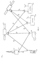
- FIG 1 An exemplary wireless communication system in which embodiments of the invention are useful, is illustrated in FIG 1 . It is contemplated that this communication system uses CDMA type communication signals, but this is not required.
- one base station 112 two satellites 116 and 118, and two associated gateways or hubs 120 and 122 are shown for effecting communications with two remote mobile units 124 and 126.
- the base stations and satellites/gateways are components of separate communication systems, referred to as being terrestrial and satellite based, although this is not necessary.
- the total number of base stations, gateways, and satellites in such systems depend on desired system capacity and other factors well understood in the art.
- Mobile units 124 and 126 each include a wireless communication device such as, but not limited to, a cellular telephone, a data transceiver or transfer device (e.g., computers, personal data assistants, facsimile), or a paging or position determination receiver, and can be hand-held or vehicle-mounted as desired.
- a wireless communication device such as, but not limited to, a cellular telephone, a data transceiver or transfer device (e.g., computers, personal data assistants, facsimile), or a paging or position determination receiver, and can be hand-held or vehicle-mounted as desired.
- the mobile units are illustrated as hand-held telephones.
- teachings of the invention are applicable to fixed units or other types of terminals were remote wireless service is desired, including 'indoor' as well as 'open air' locations.
- base station gateway, hub, and fixed station are sometimes used interchangeably in the art, with gateways generally understood as comprising specialized base stations that direct communications through satellites.
- Mobile units are also referred to as subscriber units, user terminals, mobile stations, or simply “users,” “mobiles,” or “subscribers” in some communication systems, depending on preference.
- beams from satellites 116 and 118 cover different geographical areas in predefined patterns. Beams at different frequencies, also referred to as CDMA channels or 'sub-beams,' can be directed to overlap the same region. It is also readily understood by those skilled in the art that beam coverage or service areas for multiple satellites, or cellular base stations, might be designed to overlap completely or partially in a given region depending on the communication system design and the type of service being offered, and whether space diversity is being achieved. For example, each may provide service to different sets of users with different features at different frequencies, or a given mobile unit may use multiple frequencies and/or multiple service providers, each with overlapping geophysical coverage.
- a variety of multi-satellite communication systems have been proposed with an exemplary system employing on the order of 48 or more satellites, traveling in eight different orbital planes in LEO orbits for servicing a large number of mobile units.
- teachings of the present invention are applicable to a variety of satellite system and gateway configurations, including other orbital distances and constellations.
- the embodiments are equally applicable to terrestrial-based systems of various base station configurations.
- FIG. 1 some possible signal paths are illustrated for communications being established between mobile units 124 and 126 and base station 112, or through satellites 116 and 118, with gateways 120 and 122.
- the base station-mobile unit communication links are illustrated by lines 130 and 132.
- the satellite-mobile unit communication links between satellites 116 and 118, and mobile units 124 and 126 are illustrated by lines 140, 142, and 144.
- the gateway-satellite communication links, between gateways 120 and 122 and satellites 116 and 118, are illustrated by lines 146, 148, 150, and 152.
- Gateways 120 and 122, and base station 112 may be used as part of one or two-way communication systems or simply to transfer messages or date to mobile units 124 and 126.
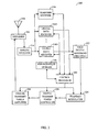
- Transceiver 200 uses at least one antenna 210 for receiving communication signals which are transferred to an analog receiver 214, where they are downconverted, amplified, and digitized.
- a duplexer element 212 is typically used to allow the same antenna to serve both transmit and receive functions. However, some systems employ separate antennas for operating at different transmit and receive frequencies.
- the digital communication signals output by analog receiver 214 are transferred to at least one digital data receiver 216 A and at least one digital searcher receiver 218. Additional digital data receivers 216 B -216 N can be used to obtain desired levels of signal diversity, depending on the acceptable level of unit complexity, as would be apparent to one skilled in the relevant art.
- At least one mobile unit control processor 220 is coupled to digital data receivers 216 A -216 N and searcher receiver 218.
- Control processor 220 provides, among other functions, basic signal processing, timing, power and handoff control or coordination, and selection of frequency used for signal carriers. Another basic control function often performed by control processor 220 is the selection or manipulation of PN code sequences or orthogonal functions to be used for processing communication signal waveforms.
- Signal processing by control processor 220 can include a determination of relative signal strength and computation of various related signal parameters. Such computations of signal parameters, such as timing and frequency may include the use of additional or separate dedicated circuitry to provide increased efficiency or speed in measurements or improved allocation of control processing resources.
- the outputs of digital data receivers 216 A -216 N are coupled to digital baseband circuitry 222 within the mobile unit.
- User digital baseband circuitry 222 comprises processing and presentation elements used to transfer information to and from a mobile unit user. That is, signal or data storage elements, such as transient or long term digital memory; input and output devices such as display screens, speakers, keypad terminals, and handsets; A/D elements, vocoders and other voice and analog signal processing elements; etc., all form parts of the user digital baseband circuitry 222 using elements well known in the art. If diversity signal processing is employed, user digital baseband circuitry 222 can comprise a diversity combiner and decoder. Some of these elements may also operate under the control of, or in communication with, control processor 220.
- user digital baseband circuitry 222 When voice or other data is prepared as an output message or communications signal originating with the mobile unit, user digital baseband circuitry 222 is used to receive, store, process, and otherwise prepare the desired data for transmission. User digital baseband circuitry 222 provides this data to a transmit modulator 226 operating under the control of control processor 220. The output of transmit modulator 226 is transferred to a power controller 228 which provides output power control to a transmit power amplifier 230 for final transmission of the output signal from antenna 210 to a gateway.
- Mobile unit 124,126 can also employ one or more precorrection elements (not shown), as desired, in the transmission path to adjust the frequency of outgoing signals. This can be accomplished using one or a variety of well known techniques. Mobile unit 200 can also employ a precorrection element in the transmission path to adjust the timing of outgoing signals, using well known techniques of adding or subtracting delay in the transmission waveform.
- Information or data corresponding to one or more measured signal parameters for received communication signals, or one or more shared resource signals can be sent to the gateway using a variety of techniques known in the art.
- the information can be transferred as a separate information signal or be appended to other messages prepared by user digital baseband circuitry 222.
- the information can be inserted as predetermined control bits by transmit modulator 226 or transmit power controller 228 under control of control processor 220. See for example U. S. Patent Nos.
- Digital receivers 216A- N and searcher receiver 218 are configured with signal correlation elements to demodulate and track specific signals.
- Searcher receiver 218 is used to search for pilot signals, or other relatively fixed pattern strong signals, while digital receivers 216A- N are used to demodulate other signals associated with detected pilot signals. Therefore, the outputs of these units can be monitored to determine the energy in, or frequency of, the pilot signal or other signals.
- These receivers also employ frequency tracking elements that can be monitored to provide current frequency and timing information to control processor 220 for signals being demodulated.
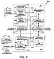
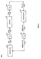
- FIG. 3 An exemplary transmission and reception apparatus 300 for use in gateways 120 and 122 is illustrated in FIG. 3 .
- the portion of gateway 120, 122 illustrated in FIG. 3 has one or more analog receivers 314 connected to an antenna 310 for receiving communication signals which are then downconverted, amplified, and digitized using various schemes well known in the art. Multiple antennas 310 are used in some communication systems. Digitized signals output by analog receiver 314 are provided as inputs to at least one digital receiver module, indicated by dashed lines generally at 324.
- Each digital receiver module 324 corresponds to signal processing elements used to manage communications between a gateway 120, 122 and one mobile unit 124,126, although certain variations are known in the art.
- One analog receiver 314 can provide inputs for many digital receiver modules 324, and a number of such modules are typically used in gateways 120, 122 to accommodate all of the satellite beams and possible diversity mode signals being handled at any given time.
- Each digital receiver module 324 has one or more digital data receivers 316 and a searcher receiver 318. Searcher receiver 318 generally searches for appropriate diversity modes of signals other than pilot signals. Where implemented in the communication system, multiple digital data receivers 316 A -316 N are used for diversity signal reception.
- the outputs of digital data receivers 316 are provided to subsequent baseband processing elements 322 comprising apparatus well known in the art and not illustrated in further detail here.
- Exemplary baseband apparatus includes diversity combiners and decoders to combine multipath signals into one output for each subscriber.
- Exemplary baseband apparatus also includes interface circuits for providing output data, typically to a digital switch or network.
- a variety of other known elements such as, but not limited to, vocoders, data modems, and digital data switching and storage components may form a part of baseband processing elements 322. These elements operate to process, control, or direct the transfer of voice and data signals to one or more transmit modules 334.
- Signals to be transmitted to mobile units are each coupled to one or more appropriate transmit modules 334.
- a typical gateway uses a number of such transmit modules 334 to provide service to many mobile units 124, 126 at a time, and for several satellites and beams at a time.
- the number of transmission modules 334 used by gateway 120, 122 is determined by factors well known in the art, including system complexity, number of satellites in view, subscriber capacity, degree of diversity chosen, and the like.
- Each transmit module 334 includes a transmit modulator 326 which spread spectrum modulates data for transmission.
- Transmit modulator 326 has an output coupled to a digital transmit power controller 328, which controls the transmission power used for the outgoing digital signal.
- Digital transmit power controller 328 applies a minimum level of power for purposes of interference reduction and resource allocation, but applies appropriate levels of power when needed to compensate for attenuation in the transmission path and other path transfer characteristics.
- At least one PN generator 332 is used by transmit modulator 326 in spreading the signals. This code generation can also form a functional part of one or more control processors or storage elements used in gateway 120,122.
- the output of transmit power controller 328 is transferred to a summer 336 where it is summed with the outputs from other transmit power control circuits. Those outputs are signals for transmission to other mobile units 124, 126 at the same frequency and within the same beam as the output of transmit power controller 328.
- the output of summer 336 is provided to an analog transmitter 338 for digital-to-analog conversion, conversion to the appropriate RF carrier frequency, further amplification and output to one or more antennas 340 for radiating to mobile units 124, 126.
- Antennas 310 and 340 may be the same antennas depending on the complexity and configuration of the system.
- one or more precorrection elements or precorrectors can be disposed in the transmission path to adjust the output frequency based on known Doppler for the link through which communication is established. Techniques or elements used to adjust the frequency of signals prior to transmission are well known in the art. In addition, the same or another precorrector can operate to adjust the output timing based on known propagation delay and code Doppler for the link through which communication is established. Techniques or elements used to adjust the timing of signals prior to transmission are also well known in the art.
- At least one gateway control processor 320 is coupled to receiver modules 324, transmit modules 334, and baseband circuitry 322; these units may be physically separated from each other.
- Control processor 320 provides command and control signals to effect functions such as, but not limited to, signal processing, timing signal generation, power control, handoff control, diversity combining, and system interfacing.
- control processor 320 assigns PN spreading codes, orthogonal code sequences, and specific transmitters and receivers for use in subscriber communications.
- Control processor 320 also controls the generation and power of pilot, synchronization, and paging channel signals and their coupling to transmit power controller 328.
- the pilot channel is simply a signal that is not modulated by data, and may use a repetitive unchanging pattern or non-varying frame structure type input to transmit modulator 326, effectively transmitting only the PN spreading codes applied from PN generator 332.
- control processor 320 can be coupled directly to the elements of a module, such as transmit module 324 or receive module 334, each module generally comprises a module-specific processor, such as transmit processor 330 or receive processor 321, which controls the elements of that module.
- control processor 320 is coupled to transmit processor 330 and receive processor 321, as shown in FIG. 3 .
- Transmit processor 330 controls generation of, and signal power for, pilot, synchronization, paging signals, and traffic channel signals, and their respective coupling to power controller 328.
- Receiver processor 321 controls searching, PN spreading codes for demodulation and monitoring received power.
- a received power detector 323 can be used to detect the power in the signal as determined by the analog receiver 314, or by monitoring the energy in the outputs of digital receivers 316. This information is provided to transmit power controller 328 to adjust the output power as part of a power control loop as is discussed in further detail below. This information can also be provided to receiver processor 321 or control processor 320 as desired. This information can also incorporated as a function in receive processor 321.
- gateways 120 and 122 receive information such as received signal strength, frequency measurements, or other received signal parameters from mobile units in communication signals. This information can be derived from the demodulated outputs of data receivers 316 by receive processors 321. Alternatively, this information can be detected as occurring at predefined locations in the signals being monitored by control processor 320, or receive processors 321, and transferred to control processor 320. Control processor 320 may use this information to control the timing and frequency, as well as output power, of signals being transmitted and processed using transmit power controllers 328 and analog transmitter 338.
- a communication signal s(t) is transmitted by a gateway ( 120, 122 ) to a mobile unit ( 124, 126 ) using a gateway generated carrier frequency of A 0 .
- the forward link signal experiences time delays, a propagation delay, frequency shifts due to Doppler, and other effects.
- the forward link signal experiences these effects first, while transmitting from a gateway to the satellites (i.e., on an uplink portion of the forward link signal), and second, when transmitting from satellites to mobile units (i.e., on a downlink portion of the forward link signal).
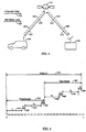
- FIG. 4 illustrates the various signals transmitted in communication system 100 employing one or more satellite repeaters 116.
- Gateway 120 transmits a forward link signal 410 to mobile unit 124 via satellite repeater 116.
- Forward link signal 410 is comprised of an uplink portion 412 from gateway 120 to satellite repeater 116 and a downlink portion 414 from satellite repeater 116 to mobile unit 124.
- Mobile unit 124 transmits a reverse link signal 420 to gateway 120 via satellite repeater 116.
- Reverse link signal 420 is comprised of an uplink portion 422 from mobile unit 124 to satellite repeater 116 and a downlink portion 424 from satellite repeater 116 to gateway 120.
- FIG. 5 is an illustration of timing of a power control command transferred over forward link 410 and of the response (i.e., corresponding change in transmit power level) of the power control command over reverse link 420. Timing of the power control command sent by gateway 120 to mobile unit 124 will now be discussed with respect to FIG. 4 and FIG. 5 .
- gateway 120 transmits the power control command over forward link signal 410 to satellite repeater 116
- the power control command experiences a propagation delay 510 (t 1 ) on uplink portion 412 as a result of a distance between gateway 120 and satellite repeater 116.
- the power control command experiences a processing delay 520 (t s ) as satellite repeater 116 processes uplink portion 412 in order to transmit downlink portion 414 to mobile unit 124. That is, the power control command experiences processing delay 520 when, for example, the satellite performs frequency conversion or beam forming.
- the power control command experiences a propagation delay 530 (t 2 ) on downlink portion 414 as a result of a distance between satellite repeater 116 and mobile unit 124.
- the power control command is processed by control processor 220 and digital transmit power controller 228. As a result of this processing, mobile unit 124 adjusts a transmit power of reverse link signal 420. During this processing, the power control command experiences a processing delay 540 (t m ).
- Forward link delay 545 represents the amount of delay between a time when the power control command is sent by gateway 120 and when an adjustment to the transmit power of reverse link signal 420 occurs.
- Timing of a response to the power control command performed by mobile unit 124 on reverse link signal 420 will also be discussed with respect to FIG. 4 and FIG. 5 .
- mobile unit 124 adjusts the transmit power of reverse link signal 420
- mobile unit 124 transmits uplink portion 422 to satellite repeater 116.
- the response to the power control command (i.e., change in the transmit power level for reverse link signal) experiences a propagation delay 550 (t 3 ) on uplink portion 422 as a result of a (current) distance between mobile unit 124 and satellite repeater 116.
- the response to the power control command experiences a processing delay 560 (t s ) as satellite repeater 116 processes uplink portion 422 in order to transmit downlink portion 424 to gateway 120.
- the response to the power control command experiences a propagation delay 570 (t 4 ) on downlink portion 424 as a result of a distance between satellite repeater 116 and gateway 120.
- the response to the power control command is processed by receivers 314, 316 and 318 and by control processor 320.
- gateway 120 detects a received power level of reverse link signal 420 and determines a new power control command based on the received power level and a desired power level as discussed above.
- the response to the power control command i.e., detected power level in reverse link signal
- t reverse t 3 + t s + t 4 + t g .
- Reverse link delay 585 represents the amount of delay between a time when the response to the power control command is sent by mobile unit 124 and when the response is detected by gateway 120.
- t 1 , t 2 , t 3 , and t 4 comprise the majority of delay 590.
- each of the propagation delays 545, 585 is on the order of 9-26 ms.
- Total delay 590 is on the order of 18-53 ms.
- Total delay 590 is also referred to as round-trip propagation delay 590.
- gateways 120 In satellite communication systems, gateways 120 generally have a fairly accurate estimation of delays imposed on signals traversing between gateways 120 and satellites 116 (i.e., t 1 and t 4 ) at any given time because of the well defined orbital patterns used by satellites 116, and known locations of gateways 120 relative to those orbits.
- FIG. 6 shows a power control loop 600.
- Power control loop 600 includes a controller 610, a first delay block 620, a process 630, a second delay block 640, a compensator 650, and a third delay block 660.
- controller 610 located in mobile unit 124, represents the power control loop functions in transceiver 200, particularly those of control processor 220 and digital transmit power controller 228, as shown in FIG. 2 .
- compensator 650 located in gateway 120, represents the power control loop functions in control processor 320, as shown in FIG. 3 .
- Controller 610 outputs a signal 615 (shown as x(t) in FIG. 6 ) at a particular transmit power level.
- signal 615 represents uplink portion 422 ,of reverse link signal 420 from mobile unit 124 to gateway 120.
- Signal 615 experiences a delay through delay block 620 of ⁇ 1 .
- ⁇ 1 corresponds to an estimate of propagation delay 550 (shown as t 3 in FIG. 5 ), as discussed above.
- delay block 620 signal 615 is transformed into a signal 625 (shown as x(t- ⁇ 1 ) in FIG. 6 ).
- Signal 625 corresponds to signal 615 delayed in time by ⁇ 1 .
- propagation delays 510, 530, 550, and 570 dominate processing delays 520, 540, 560, and 580 and, thus, processing delays 520, 540, 560, and 580 are ignored.
- accurate estimates of such processing delays could be used, when known.
- ⁇ 1 is approximated as t 3 .
- ⁇ 2 is approximated as t 4
- ⁇ 3 is approximated as t 1 +t 2 .
- processing delays 520, 540, 560, and 580 are significant in comparison to propagation delays 510, 530, 550, and 570, they may be accounted for in ⁇ 1 , ⁇ 2 , and ⁇ 3 as well.
- propagation delay includes any processing delays as well.
- Process 630 represents attenuation and other effects such as fading, as signal 625 is propagated from mobile unit 124 to gateway 120.
- process 630 represents a transfer function of the atmosphere/environment through which signal 625 passes as it propagates from mobile unit 124 to gateway 120 via satellite 116.
- a signal 635 (shown as y(t- ⁇ 1 ) in FIG. 6 ) results from process 630.
- Signal 635 represents attenuated and faded signal 625 as would be apparent.
- signal 635 is delayed by delay block 640.
- Signal 635 experiences a delay through delay block 640 of ⁇ 2 .
- ⁇ 2 corresponds to an estimate of propagation delay 570 (shown as t 4 in FIG. 5 ) as discussed above.
- signal 635 is transformed into a signal 645 (shown as y(t- ⁇ 1 - ⁇ 2 ) in FIG. 6 ).
- Signal 645 corresponds to signal 635 delayed in time by ⁇ 2 .
- the delay ⁇ 2 represents the propagation delay of downlink portion 424 of reverse link signal 420 as discussed above.
- Signal 645 represents the signal received by gateway 120 as transmitted from mobile unit 124.
- signal 645 represents the signal transmitted by mobile unit 124 after it has been delayed by ⁇ 1 and ⁇ 2 , and attenuated and faded according to process 630.
- Compensator 650 receives signal 645 and determines a power level of signal 645 according to well-known methods. As discussed above, it is desirable that the power level of signal 645 match a minimum desired power level. For example, if the power level of signal 645 is less than the desired power level, then compensator 650 issues a power control command that instructs controller 610 to increase the transmit power of signal 615. On the other hand, if the power level of signal 645 is greater than the desired power level, then compensator 650 issues a power control command that instructs controller 610 to reduce the transmit power level of signal 615.
- compensator 650 issues a single-bit power control command.
- compensator 650 either issues a power-up command or a power-down command.
- a general discussion of such a power control system is disclosed in U. S. Patent No. 5,396,516, which issued March 7, 1995 , entitled "Method And Apparatus For The Dynamic Modification Of Control Parameters In A Transmitter Power Control System," which is assigned to the assignee of the present invention .
- a power-up command instructs controller 610 to increase the transmit power of signal 615 by a fixed amount, e.g., 1 dB.
- a power-down command instructs controller 610 to decrease the transmit power of signal 615 by a fixed amount, e.g., 1 dB. As would be apparent, different fixed amounts could be used. As would also be apparent, more bits of power control commands could be implemented which would provide varying levels of power control adjustments.
- compensator 650 issues a power-up command when the power level of signal 645 is less than a desired power level. At all other times, compensator 650 issues a power-down command. As would be apparent, additional levels could be implemented that would provide for a zero power command when the received power level of signal 645 is within a specific range of desired power levels.
- a power-up command would increase the power level of signal 615 by a first fixed amount and a power-down command would decrease the power level of signal 615 by a second fixed amount, where the first fixed amount is less than the second fixed amount.
- power control loop 600 would reduce the power level of signal 615 much quicker than it would increase the power level of signal 615. This embodiment responds quicker to reduce the power levels of signals in the CDMA communication system, which, as discussed above, reduces an amount of interference any one particular signal experiences.
- Compensator 650 outputs a command 655 (shown as CMD r (t- ⁇ 1 - ⁇ 2 ) in FIG. 6 ).
- power control command 655 is either a power-up command or a power-down command.
- Power control command 655 is output by compensator 650 in response to signal 615 which has been delayed due to propagation on reverse link 420 by an amount equal to ⁇ 1 + ⁇ 2 (i.e., the one way propagation delay).
- Power control command 655 is transmitted from gateway 120 to mobile unit 124 via forward link 410. As power control command 655 propagates over forward link 410, power control command 655 experiences another propagation delay represented by delay block 660. Delay block 660 delays power control command 655 by an amount ⁇ 3 which corresponds to the propagation delays on both uplink portion 412 and downlink portion 414 of forward link 410. In this embodiment of the present invention, ⁇ 3 corresponds to the sum of delay 510 and delay 530 (shown in FIG. 5 as t 1 and t 2 ).
- the output of delay block 660 is a signal 665 (shown as CMD r (t- ⁇ 1 - ⁇ 2 - ⁇ 3 ) in FIG. 6 ).
- Signal 665 represents power control command 655 delayed by the propagation delay between gateway 120 and mobile unit 124.
- Signal 665 is received by controller 610.
- Signal 665 represents a power control command to controller 610.
- signal 665 instructs controller 610 to either increase the transmit power of signal 615 by a fixed amount or to decrease the transmit power of signal 61 by a fixed amount.
- a total delay of ⁇ 1 + ⁇ 2 + ⁇ 3 seconds has been experienced by signal 615 in power control loop 600.
- ⁇ 1 + ⁇ 2 + ⁇ 3 seconds have passed between a time when a signal 615 was transmitted from mobile unit 124 and when a power control command sent by compensator 650 to change a power level of that signal 615 is received by mobile unit 124.
- ⁇ 1 + ⁇ 2 + ⁇ 3 is significantly large (e.g., exceeds the loop iteration time of controller 610 ), the delay poses a significant problem in controlling the power level of signal 615.
- compensator 650 will not detect a change in the power level of signal 615 in response to a command until an amount of time equal to ⁇ 1 + ⁇ 2 + ⁇ 3 has passed. If the iteration time of compensator 650 is small in comparison to ⁇ 1 + ⁇ 2 + ⁇ 3 , compensator 650 will have issued multiple power control commands 655 before any of the responses to those power control commands 655 are detected as signal 645. This introduces a phenomenon in power control loop 600 referred to as a limit cycle.
- FIG. 7 illustrates an operation of a conventional compensator 650 in further detail.
- Conventional compensator 650 includes a desired power level (or other corresponding parameter) threshold 710, a power level (corresponding parameter) detector 730, and a comparator 720.
- Power level detector 730 determines a power level of signal 645 according to well-known techniques in communication systems.
- Comparator 720 determines a difference between the power level of signal 645 from power level detector 730 and desired power level threshold 710. Comparator 720 outputs a power-up command when the power level of signal 645 is less than desired power level threshold 710.
- Comparator 720 issues a power-down command when the power level of signal 645 is greater than desired power level threshold 710.
- FIG. 8 illustrates the operation of conventional compensator 650.
- FIG. 8 includes two plots: a received power plot 810 and a power control command plot 830.
- Received power plot 810 represents an exemplary received power level 820 of signal 645 received by conventional compensator 650 over time.
- Power control command plot 830 represents a power control command 840 output by conventional compensator 650 in response to received power level 820 over time. The following is a discussion of the operation of conventional compensator 650 in response to receive power level 820.
- received power level 820 is -88.5 dB.
- desired power level threshold 710 is set at -88 dB, with this level being chosen in each communication system according to known principles.
- received power level 820 is less than desired power level 710.
- conventional compensator 650 issues a power-up command to controller 610 indicating that controller 610 should increase the transmit power of signal 615.
- power-up commands are indicated as +1 and power-down commands are indicated as -1 in power control command plot 830 .
- a first assumption is that the loop iteration time of conventional compensator 650 is arbitrarily selected as one-fourth of the total delay ⁇ 1 + ⁇ 2 + ⁇ 3 as a result of propagation delays.
- four power control commands 655 are issued from conventional compensator 650 before the first power control command 655 is detected as received power level 820 by conventional compensator 650.
- a second assumption is that a power-up command instructs controller 610 to increase the power level of signal 615 by 1 dB and that a power-down command instructs controller 610 to decrease the power level of signal 615 by 1 dB.
- received power level 820 has increased by 1 dB to -87.5 dB.
- conventional compensator 650 determines that received power level 820 exceeds desired power level threshold 710 and, therefore, issues a power-down command. As discussed above, the power-down command indicates to controller 610 to decrease the transmit power of signal 615.
- received power level 820 overshoots desired power level threshold 710 by 3.5 dB.
- This limit cycle represents the best operation of which conventional compensator 650 is capable. That is, the limit cycle represents how well or how closely compensator 650 can hold signals to a specific desired power level. This represents a waste in power which reduces system capacity and mobile unit operating time.
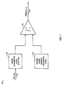
- FIG. 9 illustrates an improved compensator 900
- Compensator 900 replaces conventional compensator 650 in FIG. 6 .
- Compensator 900 accounts for power control commands 655 that had been issued by compensator 900 whose responses have not had time to propagate back to compensator 900.
- compensator 900 includes desired power level threshold 710, power level detector 730, comparator 720, a pending command accumulator 910, and a summer 920.
- Power level detector 730 and desired power level threshold 710 operate as described above with respect to conventional compensator 650.
- the number of power control commands that are accumulated depends on the propagation delays experienced in forward link signal 410 and reverse link signal 420, and the iteration time of control loop 600. For example, if the total propagation delay is 50 ms and the iteration period of control loop 600 is 12.5 ms, four power control commands 655 are accumulated by pending command accumulator 910.
- Pending command accumulator 910 outputs a power level corresponding to the sum 915 of power control commands whose responses have not been detected to summer 920.
- Summer 920 adds the output of pending command accumulator 910 to received power level 645.
- Summer 920 outputs the sum of these signals to comparator 720.
- Comparator 720 issues a power-up command if the output of summer 920 is less than desired power level threshold 710. Comparator 720 issues a power-down command when the output of summer 920 is greater than desired power level threshold 710.
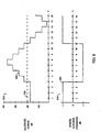
- FIG. 10 An operation of compensator 900 is illustrated in FIG. 10 .
- the same assumptions are made here as were made above with respect to FIG. 8 , solely for purposes of illustration. Those assumptions are that four power control commands are issued before the effect of the first is detected and that the power-up and power-down commands change the transmit power level of signal 615 by 1 dB.
- FIG. 10 includes a received power level plot 1010, showing received power level 1020 versus time; a pending command accumulator output plot 1030, showing a pending command accumulator output 1040 versus time; and a power control command plot 1050, showing a power control command or commands 1060 versus time.
- received power level 1020 is -88.5 dB.
- a desired power level threshold 710 is set at -88 dB.
- received power level 1020 is less than desired power level threshold 710.
- power control command 1060 oscillates between +1 and -1 as received power level 1020 oscillates about desired power level threshold 710. This represents the limit cycle of compensator 900. Compared with the limit cycle of received power level 820 in FIG. 8 , compensator 900 dramatically improves the performance of power control loop 600.
- received power level 1020 is added to pending command accumulator output 1040 and input to comparator 720.
- received power level 1020 oscillates about -86 dB. That is, a control loop with a loop delay (e.g., propagation delay) that is large with respect to the loop iteration time (i.e., sample rate or update rate of the loop) has some oscillatory behavior which is also affected by the level of quantization.
- a loop delay e.g., propagation delay
- the loop iteration time i.e., sample rate or update rate of the loop
- compensator 900 accounts for commands that have not yet propagated through power control loop 600.
- Pending command accumulator 910 accounts for these power control commands so that future power control commands are based on their pending, but not yet detected, changes in received power level 1020.
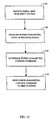
- FIG. 11 is a flowchart illustrating the operation of the present invention.
- signal 645 is received at compensator 900 located at a first station.
- the first station corresponds to gateway 120.
- compensator 900 is located in mobile unit 124.
- power level detector 730 measures a power level of signal 645 according to well-known techniques.
- compensator 900 determines a power control command 655 based on the measured power of signal 645, desired power level 710, and a sum 915 of pending power control commands 655.
- power control command 655 is sent to the first station so that the power of signal 645 can be increased or decreased as appropriate.
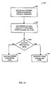
- FIG. 12 is a flowchart illustrating the operation of compensator 900 in further detail. Specifically, FIG. 12 illustrates the operation of step 1130 discussed above with reference to FIG. 11 .
- pending command accumulator 910 accumulates pending power control commands 655. As discussed above, pending control commands 655 are those control commands whose responses have not had time to propagate back to compensator 900.
- a power level corresponding to pending control commands 655 is added to the power level of received signal 645.
- a decision step 1230 the sum of the pending control commands 655 and the power of the received signal 645 is compared with desired power level 710.
- a power command is issued to increase the power level of signal 645. If the sum of the pending control commands 655 and the power of the received signal 645 is not less than desired power level 710, in a step 1240, a power command is issued to decrease the power level of signal 645. As discussed above, in a preferred embodiment of the present invention, a power-up command is issued to increase the power level of signal 645 and a power-down command is issued to decrease the power level of signal 645.
- the same or additional compensator elements 900 could be used to detect other operating parameters of communication signals such as frequency, code timing, and so forth. Commands, such as up and down or advance and retard commands, can then be generated as appropriate, which mobile unit 124 uses to implement changes in such parameters. For example, mobile unit 124 can be told to adjust the operating frequency for return link signals to counter drift in mobile unit's 124 local oscillator center frequency, or code timing cold be changed to compensate for Doppler effects, and so forth. Many parameters and processes are well known for which compensation could be effected using commands, but which also suffer from the same time or transfer delays experienced by the power control commands discussed above.
- measurement of power or power relative to a threshold can occur at mobile unit 124, with that information being transmitted back to gateway 120 where compensation processing occurs to adjust the power of the gateway signals.
- This approach may be preferred because it minimizes resource requirements and complexity in mobile unit 124, and uses the greater computation resources of gateways 120.
- commands are not transmitted as signals 655 and 665 which are delayed, but as information signals which are delayed. The delay values are the same otherwise.
- Embodiments have also been described in terms of a single-bit system wherein a power-up command or a power-down command was issued by compensator 900 instructing controller 610 to increase or decrease transmit power by a fixed amount.
- compensator 900 instructing controller 610 to increase or decrease transmit power by a fixed amount.
- different schemes could be implemented wherein power control command is quantized depending on a difference between desired power level 710 and received power level 645 as would be apparent.
Description
- The present invention relates generally to spread spectrum communication systems, and more particularly, to a method and apparatus for adjusting signal parameters in such systems in the presence of control loop or path delay in detecting signal status and using a controllable element to effect changes in the detected status. The invention further relates to using transmit power as a parameter that is controlled to minimize interference among simultaneously operating transmitters and to maximize the quality of individual communications.
- A variety of multiple access communication systems and techniques have been developed for transferring information among a large number of system users. However, spread spectrum modulation techniques, such as code division multiple access (CDMA) spread spectrum techniques, provide significant advantages over other modulation schemes, especially when providing service for a large number of communication system users. The use of CDMA techniques in multiple access communication systems is disclosed in
U. S. Patent No. 4,901,307, which issued February 13, 1990 , entitled "Spread Spectrum Multiple Access Communication System Using Satellite Or Terrestrial Repeaters," andU. S. Patent No 5691974 , entitled "Method And Apparatus For Using Full Spectrum Transmitted Power In A Spread Spectrum Communication System For Tracking Individual Recipient Phase Time And Energy," both of which are assigned to the assignee of the present invention . - These patents disclose communication systems in which a large number of generally mobile or remote system users or subscriber units ("mobile units") employ at least one transceiver to communicate with other mobile units, or users of other connected systems, such as a public telephone switching network. Communication signals are transferred either through satellite repeaters and gateways, or directly to terrestrial base stations (also sometimes referred to as cell-sites or cells).
- In CDMA communications, the frequency spectrum can be reused multiple times, thereby permitting an increase in the number of mobile units. The use of CDMA results in a much higher spectral efficiency than can be achieved using other multiple access techniques. However, in order to maximize overall communication system capacity and maintain acceptable levels of mutual interference and signal quality, the transmitted power of signals within the system must be controlled so as to maintain, at a minimum level, the amount of power required for any given communication link. By controlling the transmitted signal power at or near the minimum level, interference with other mobile units is reduced.
- In communication systems employing satellites, the communication signals typically experience fading that is characterized as Rician. Accordingly, the received signal consists of a direct component summed with multiple reflected components having Rayleigh fading statistics. The power ratio between the direct component and the reflected components is typically on the order of 6-10 dB, depending upon the characteristics of the mobile unit antenna and the environment in which the mobile unit operates.
- In contrast to satellite communication systems, communication signals in terrestrial communication systems typically experience signal fading that typically consists only of the reflected, or Rayleigh, components, without a direct component. Thus, the terrestrial communication signals experience a more severe fading environment than the satellite communication signals where Rician fading is the dominant fading characteristic.
- The Rayleigh fading in the terrestrial communication system is caused by the communication signals being reflected from many different features of the physical environment. As a result, a signal arrives almost simultaneously at a mobile unit receiver from many directions with different transmission delays. At the UHF frequency bands usually employed by mobile radio communications including those of cellular mobile telephone systems, significant phase differences in signals traveling on different paths may occur. The possibility for destructive summation of the signals may result in occasional deep fades.
- In order to provide a full-duplex channel to allow both directions of a conversation to be simultaneously active, such as provided by the conventional wired telephone system, one frequency band is used for an outbound or forward link, (i.e. transmission from the gateway or cell-site transmitter to the mobile unit receiver), and a different frequency band is utilized for the inbound or reverse link, (i.e. transmission from the mobile unit transmitter to the gateway or cell-site receiver). This frequency band separation allows a mobile unit transmitter and receiver to be active simultaneously without feedback or interference from the transmitter into the receiver.
- However, using different frequency bands has significant implications for power control. Using different frequency bands causes multipath fading to be independent processes for the forward and reverse links. Forward link path loss cannot simply be measured and have it assumed that the same path loss is present on the reverse link.
- Furthermore, in a cellular mobile telephone system the mobile phone is capable of communications through multiple cell-sites as disclosed in
US , entitled "Method And System For Providing A Soft Handoff In Communications In A CDMA Cellular Telephone System". In communications with multiple cell-sites, the mobile unit and cell-sites include a multiple receiver scheme as disclosed in the just mentioned application and further detailed inPatent No 5 101 501US , entitled "Diversity Receiver in a CDMA Cellular Telephone System".Patent No 5 109 390 - One method of power control is to have either the mobile unit or the gateway first measure the power level of a received signal. This power measurement is used, along with a knowledge of transponder downlink transmit power levels for each satellite being used and knowledge of mobile unit and gateway receiver sensitivity, to estimate path loss for each channel of the mobile unit. Either the base station or the mobile unit transceiver can then determine the appropriate power to be used for signal transmissions to the mobile unit, taking into account the path loss estimate, a transmitted data rate, and a satellite receiver sensitivity. In the case of the mobile unit, a request can be made for more or less power in response to such measurements and determinations. At the same time, the gateway can increase or decrease power in response to such requests, or in response to its own measurements.
- The signals transmitted by the mobile unit to the satellite are relayed by the satellite to the gateway and generally on to a communication system control system. The gateway or the control system measures the received signal power from the transmitted signals. The gateway then determines the deviation in the received power level from a minimum which is necessary to maintain the desired level of communications. Preferably, the minimum desired power level is that power level necessary to maintain quality communications while reducing system interference.
- The gateway then transmits a power control command signal to the mobile unit so as to adjust or "fine tune" the transmit power of the mobile unit. This command signal is used by the mobile unit to change the transmit power level closer to the minimum level required to maintain the desired communications. As channel conditions change, typically due to motion of the mobile unit, or satellite, the mobile unit responds to the control commands from the gateway to continually adjust the transmit power level so as to maintain a proper power level.
- In this configuration, the control commands from the gateway are referred to as power control feedback. The power control feedback from the gateway is generally quite slow due to round trip propagation delays through the satellites. A one way propagation delay employing a typical LEO satellite orbit (879 miles) is on the order of 9-26 ms. Thus, a power control command from the gateway can reach the mobile unit up to 26 ms after it was sent. Likewise, a change in the transmitted power made by the mobile unit in response to the power control command is detected by the gateway up to 26 ms after the change was made. The total round-trip propagation delay in this system is on the order of 18-53 ms. Thus, up to 53 ms of delay may elapse between the time a power control command is sent by the gateway and the time the response (i.e., the change in the power level caused by that power control command) is detected back at the gateway.
- Thus, a transmit power control command experiences the round trip propagation delay, as well as typical processing delays, before the results of that command can be detected by the measuring unit. Unfortunately, particularly where the propagation delay is large, an adjustment to the transmit power in response to the power control command made by the mobile unit will not occur and be detected by the gateway before the next time the received power is measured at the gateway. This results in another power control command being sent to adjust the transmit power without the benefit of the previous power control command having been implemented. In fact, depending on the propagation delay and the iteration time of the power control loop, several power control commands may be pending or "propagating" before the first power control command is responded to by the mobile unit and the results detected by the gateway. As a result, the transmit power oscillates about a set point in what is referred to as a "limit cycle." That is, the transmit power over- or undershoots from a desired amount due to delays in arrival and implementation of commands.
- One possible solution to this problem is to simply increase the iteration time of the power control loop so that it more closely resembles the propagation and processing delays. However, the impact of rapid fading and sudden signal blockages experienced by the communication signals require short iteration times to prevent sudden signal loss. As a result, the transmit power may suddenly, and unnecessarily, be increased, resulting in wasted power and increased system interference.
- XP-000736745 describes predictive control loop power control for mobile CDMA systems. The transmitter power is set at the mobile station using a function of a power control multiplier (which is calculated at the mobile station according to the previous power control multiplier) and a power control bit (which has been transmitted from a base station).
-
US-A-5 542 111 describes a method for transmission power control of a mobile station. - What is needed is a method and an apparatus that quickly responds to changes in transmit signal power, or other signal parameters, requirements, and counteracts the impact of propagation and processing delays associated with corresponding control commands. It is desirable that such a method and apparatus require little additional complexity, control structure, or protocol changes in the gateways.
- Embodiments of the present invention are directed toward a method and apparatus useful for adjusting signal parameters, preferably transmit signal power, in a communication system. In particular, they are directed toward an apparatus and method for adjusting transmit power, or other operating conditions, in communications systems, such as those employing satellites, that experience significant signal propagation delays. Embodiments of the present invention counteract the impact of the propagation delays associated with power control commands sent by a gateway to a mobile unit by keeping track of the power control commands that have been previously sent to the mobile unit and whose effect on the transmit signal power has not yet been detected at the gateway.
- In one embodiment of the present invention, a power control loop located at the gateway determines a received power level of a signal transmitted from the mobile unit. The power control loop compares the received power level with a desired power level. If the received power level is less than the desired power level, a power control command is sent instructing the mobile unit to increase its transmit power. If the received power level is greater than the desired power level, a power control command is sent instructing the mobile unit to decrease its transmit power. ;
- Due to propagation delays arising from distance between the gateway and the mobile, especially in satellite-based communication systems, several power control commands, or their associated responses, may be in transit between the gateway and the mobile unit. A first set of power control commands includes power control commands that are propagating along a forward link of the communication system and have not yet reached the mobile unit. The mobile unit has not responded to the first set of power control commands by adjusting its transmit power because the power control commands have not been received.
- A second set of power control commands includes power control commands whose effects (i.e., signals with adjusted power levels) are propagating along a reverse link of the communication system and have not yet reached a gateway. The mobile unit has received and responded to these power control commands, but their corresponding adjustments in the transmit power level have not reached the gateway for detection.
- One of the features of the present invention is to keep track of both the first set of power control commands (i.e., those propagating along the forward link that have not reached the mobile user) and the second set of power control commands (i.e., those whose adjustments are propagating along the reverse link and whose adjustments have not yet been detected by the gateway) as a set of "pending" power control commands. The pending power control commands are used by the power control loop to determine new power control commands. Specifically, the pending power control commands are added to the received power level prior to comparing it with the desired power level. In this way, the pending power control commands are accounted for in subsequent determinations of new power control commands. This reduces the oscillations, referred to as "limit cycles," of the transmit power about the desired power level.
- Another feature of embodiments of the invention is that they do not require additional complexity, additional control structure, or changes in the power control command protocol of conventional communication systems. Furthermore, this technique provides similar improvements for systems that employ a multi-bit power control command protocol. Thus, changes to the power control command protocol are not required. Furthermore, embodiments of the invention can be incorporated into conventional power control loops with only minor alterations.
- The features, objects, and advantages of embodiments of the invention will become more apparent from the detailed description set forth below when taken in conjunction with the drawings in which like reference characters identify correspondingly throughout and wherein:
-
FIG.1 illustrates a typical wireless communication system in which embodiments of the present invention may be used; -
FIG. 2 illustrates an exemplary transceiver apparatus for use by a Mobile user; -
FIG. 3 illustrates an exemplary transmission and reception apparatus for use in a gateway; -
FIG. 4 illustrates a forward link and a reverse link transmission between a gateway and a mobile user; -
FIG. 5 illustrates timing of a power control command along a forward link and a reverse link of a communication system; -
FIG. 6 illustrates a power control loop; -
FIG. 7 illustrates a conventional compensator used in power control loops; -
FIG.8 illustrates a limit cycle problem of the conventional compensator; -
FIG. 9 illustrates a compensator for use in power control loops; -
FIG. 10 illustrates an improved response of the compensator including a reduction in the limit cycle; -
FIG. 11 is a flowchart illustrating the operation of the present invention; and -
FIG. 12 is a flowchart illustrating the operation of the compensator in further detail. - Embodiments of the invention are particularly suited for use in communications systems employing Low Earth Orbit (LEO) satellites. However, as would be apparent to one skilled in the relevant art, the concept of the present invention can also be applied to satellite systems that are not utilized for communications purposes. Embodiments are also applicable to satellite systems in which the satellites travel in non-LEO orbits, or to non-satellite repeater systems, if there is sufficiently large propagation delay of the signals.
- The preferred embodiment of the invention is discussed in detail below. While specific steps, configurations and arrangements are discussed, it should be understood that this is done for illustrative purposes only. A person skilled in the relevant art will recognize that other steps, configurations and arrangements can be used Embodiments could find use in a variety of wireless information and communication systems, including those intended for position determination, and satellite and terrestrial cellular telephone systems. A preferred application is in CDMA wireless spread spectrum communication systems for mobile or portable telephone service.
- An exemplary wireless communication system in which embodiments of the invention are useful, is illustrated in
FIG 1 . It is contemplated that this communication system uses CDMA type communication signals, but this is not required. In a portion of acommunication system 100 illustrated inFIG. 1 , onebase station 112, twosatellites hubs mobile units -
Mobile units - The terms base station, gateway, hub, and fixed station are sometimes used interchangeably in the art, with gateways generally understood as comprising specialized base stations that direct communications through satellites. Mobile units are also referred to as subscriber units, user terminals, mobile stations, or simply "users," "mobiles," or "subscribers" in some communication systems, depending on preference.
- Generally, beams from
satellites - A variety of multi-satellite communication systems have been proposed with an exemplary system employing on the order of 48 or more satellites, traveling in eight different orbital planes in LEO orbits for servicing a large number of mobile units. However, those skilled in the art will readily understand how the teachings of the present invention are applicable to a variety of satellite system and gateway configurations, including other orbital distances and constellations. At the same time, the embodiments are equally applicable to terrestrial-based systems of various base station configurations.
- In
FIG. 1 , some possible signal paths are illustrated for communications being established betweenmobile units base station 112, or throughsatellites gateways lines satellites mobile units lines gateways satellites lines Gateways base station 112, may be used as part of one or two-way communication systems or simply to transfer messages or date tomobile units - An
exemplary transceiver 200 for use in a mobile unit 124,126 is illustrated inFIG. 2 .Transceiver 200 uses at least oneantenna 210 for receiving communication signals which are transferred to ananalog receiver 214, where they are downconverted, amplified, and digitized. Aduplexer element 212 is typically used to allow the same antenna to serve both transmit and receive functions. However, some systems employ separate antennas for operating at different transmit and receive frequencies. - The digital communication signals output by
analog receiver 214 are transferred to at least onedigital data receiver 216A and at least onedigital searcher receiver 218. Additional digital data receivers 216B-216N can be used to obtain desired levels of signal diversity, depending on the acceptable level of unit complexity, as would be apparent to one skilled in the relevant art. - At least one mobile
unit control processor 220 is coupled todigital data receivers 216A-216N andsearcher receiver 218.Control processor 220 provides, among other functions, basic signal processing, timing, power and handoff control or coordination, and selection of frequency used for signal carriers. Another basic control function often performed bycontrol processor 220 is the selection or manipulation of PN code sequences or orthogonal functions to be used for processing communication signal waveforms. Signal processing bycontrol processor 220 can include a determination of relative signal strength and computation of various related signal parameters. Such computations of signal parameters, such as timing and frequency may include the use of additional or separate dedicated circuitry to provide increased efficiency or speed in measurements or improved allocation of control processing resources. - The outputs of
digital data receivers 216A-216N are coupled todigital baseband circuitry 222 within the mobile unit. Userdigital baseband circuitry 222 comprises processing and presentation elements used to transfer information to and from a mobile unit user. That is, signal or data storage elements, such as transient or long term digital memory; input and output devices such as display screens, speakers, keypad terminals, and handsets; A/D elements, vocoders and other voice and analog signal processing elements; etc., all form parts of the userdigital baseband circuitry 222 using elements well known in the art. If diversity signal processing is employed, userdigital baseband circuitry 222 can comprise a diversity combiner and decoder. Some of these elements may also operate under the control of, or in communication with,control processor 220. - When voice or other data is prepared as an output message or communications signal originating with the mobile unit, user
digital baseband circuitry 222 is used to receive, store, process, and otherwise prepare the desired data for transmission. Userdigital baseband circuitry 222 provides this data to a transmitmodulator 226 operating under the control ofcontrol processor 220. The output of transmitmodulator 226 is transferred to apower controller 228 which provides output power control to a transmitpower amplifier 230 for final transmission of the output signal fromantenna 210 to a gateway. - Mobile unit 124,126 can also employ one or more precorrection elements (not shown), as desired, in the transmission path to adjust the frequency of outgoing signals. This can be accomplished using one or a variety of well known techniques.
Mobile unit 200 can also employ a precorrection element in the transmission path to adjust the timing of outgoing signals, using well known techniques of adding or subtracting delay in the transmission waveform. - Information or data corresponding to one or more measured signal parameters for received communication signals, or one or more shared resource signals, can be sent to the gateway using a variety of techniques known in the art. For example, the information can be transferred as a separate information signal or be appended to other messages prepared by user
digital baseband circuitry 222. Alternatively, the information can be inserted as predetermined control bits by transmitmodulator 226 or transmitpower controller 228 under control ofcontrol processor 220. See for exampleU. S. Patent Nos. 5,383,219 , entitled "Fast Forward Link Power Control In A Code Division Multiple Access System," issued January 17, 1995;5,396,516 , entitled "Method And System For The Dynamic Modification Of Control Parameters In A Transmitter Power Control System," issued March 7, 1995; and5,267,262 , entitled "Transmitter Power Control System," issued November 30, 1993. -
Digital receivers 216A-N andsearcher receiver 218 are configured with signal correlation elements to demodulate and track specific signals.Searcher receiver 218 is used to search for pilot signals, or other relatively fixed pattern strong signals, whiledigital receivers 216A-N are used to demodulate other signals associated with detected pilot signals. Therefore, the outputs of these units can be monitored to determine the energy in, or frequency of, the pilot signal or other signals. These receivers also employ frequency tracking elements that can be monitored to provide current frequency and timing information to controlprocessor 220 for signals being demodulated. - An exemplary transmission and
reception apparatus 300 for use ingateways FIG. 3 . The portion ofgateway FIG. 3 has one or moreanalog receivers 314 connected to anantenna 310 for receiving communication signals which are then downconverted, amplified, and digitized using various schemes well known in the art.Multiple antennas 310 are used in some communication systems. Digitized signals output byanalog receiver 314 are provided as inputs to at least one digital receiver module, indicated by dashed lines generally at 324. - Each
digital receiver module 324 corresponds to signal processing elements used to manage communications between agateway analog receiver 314 can provide inputs for manydigital receiver modules 324, and a number of such modules are typically used ingateways digital receiver module 324 has one or more digital data receivers 316 and asearcher receiver 318.Searcher receiver 318 generally searches for appropriate diversity modes of signals other than pilot signals. Where implemented in the communication system, multipledigital data receivers 316A-316N are used for diversity signal reception. - The outputs of digital data receivers 316 are provided to subsequent
baseband processing elements 322 comprising apparatus well known in the art and not illustrated in further detail here. Exemplary baseband apparatus includes diversity combiners and decoders to combine multipath signals into one output for each subscriber. Exemplary baseband apparatus also includes interface circuits for providing output data, typically to a digital switch or network. - On the input side, a variety of other known elements such as, but not limited to, vocoders, data modems, and digital data switching and storage components may form a part of
baseband processing elements 322. These elements operate to process, control, or direct the transfer of voice and data signals to one or more transmitmodules 334. - Signals to be transmitted to mobile units are each coupled to one or more appropriate transmit
modules 334. A typical gateway uses a number of such transmitmodules 334 to provide service to manymobile units transmission modules 334 used bygateway - Each transmit
module 334 includes a transmitmodulator 326 which spread spectrum modulates data for transmission. Transmitmodulator 326 has an output coupled to a digital transmitpower controller 328, which controls the transmission power used for the outgoing digital signal. Digital transmitpower controller 328 applies a minimum level of power for purposes of interference reduction and resource allocation, but applies appropriate levels of power when needed to compensate for attenuation in the transmission path and other path transfer characteristics. At least onePN generator 332 is used by transmitmodulator 326 in spreading the signals. This code generation can also form a functional part of one or more control processors or storage elements used in gateway 120,122. - The output of transmit
power controller 328 is transferred to asummer 336 where it is summed with the outputs from other transmit power control circuits. Those outputs are signals for transmission to othermobile units power controller 328. The output ofsummer 336 is provided to ananalog transmitter 338 for digital-to-analog conversion, conversion to the appropriate RF carrier frequency, further amplification and output to one ormore antennas 340 for radiating tomobile units Antennas - As in the case of mobile unit 124,126, one or more precorrection elements or precorrectors can be disposed in the transmission path to adjust the output frequency based on known Doppler for the link through which communication is established. Techniques or elements used to adjust the frequency of signals prior to transmission are well known in the art. In addition, the same or another precorrector can operate to adjust the output timing based on known propagation delay and code Doppler for the link through which communication is established. Techniques or elements used to adjust the timing of signals prior to transmission are also well known in the art.
- At least one
gateway control processor 320 is coupled toreceiver modules 324, transmitmodules 334, andbaseband circuitry 322; these units may be physically separated from each other.Control processor 320 provides command and control signals to effect functions such as, but not limited to, signal processing, timing signal generation, power control, handoff control, diversity combining, and system interfacing. In addition,control processor 320 assigns PN spreading codes, orthogonal code sequences, and specific transmitters and receivers for use in subscriber communications. -
Control processor 320 also controls the generation and power of pilot, synchronization, and paging channel signals and their coupling to transmitpower controller 328. The pilot channel is simply a signal that is not modulated by data, and may use a repetitive unchanging pattern or non-varying frame structure type input to transmitmodulator 326, effectively transmitting only the PN spreading codes applied fromPN generator 332. - While
control processor 320 can be coupled directly to the elements of a module, such as transmitmodule 324 or receivemodule 334, each module generally comprises a module-specific processor, such as transmitprocessor 330 or receiveprocessor 321, which controls the elements of that module. Thus, in a preferred embodiment,control processor 320 is coupled to transmitprocessor 330 and receiveprocessor 321, as shown inFIG. 3 . In this manner asingle control processor 320 can control the operations of a large number of modules and resources more efficiently. Transmitprocessor 330 controls generation of, and signal power for, pilot, synchronization, paging signals, and traffic channel signals, and their respective coupling topower controller 328.Receiver processor 321 controls searching, PN spreading codes for demodulation and monitoring received power. - As discussed above for the user terminal, a received
power detector 323 can be used to detect the power in the signal as determined by theanalog receiver 314, or by monitoring the energy in the outputs of digital receivers 316. This information is provided to transmitpower controller 328 to adjust the output power as part of a power control loop as is discussed in further detail below. This information can also be provided toreceiver processor 321 orcontrol processor 320 as desired. This information can also incorporated as a function in receiveprocessor 321. - For certain operations, such as shared resource power control,
gateways processors 321. Alternatively, this information can be detected as occurring at predefined locations in the signals being monitored bycontrol processor 320, or receiveprocessors 321, and transferred to controlprocessor 320.Control processor 320 may use this information to control the timing and frequency, as well as output power, of signals being transmitted and processed using transmitpower controllers 328 andanalog transmitter 338. - During operation of the portion of a
communication system 100, a communication signal s(t), referred to as a forward link signal, is transmitted by a gateway (120, 122) to a mobile unit (124, 126) using a gateway generated carrier frequency of A0. The forward link signal experiences time delays, a propagation delay, frequency shifts due to Doppler, and other effects. The forward link signal experiences these effects first, while transmitting from a gateway to the satellites (i.e., on an uplink portion of the forward link signal), and second, when transmitting from satellites to mobile units (i.e., on a downlink portion of the forward link signal). Once the signal is received, there is a further delay in sending a return or reverse link signal, a propagation delay, and Doppler in the transmit from the mobile unit to the satellite (i.e., on an uplink portion of the reverse link signal) and again from the satellite to the gateway (i.e., on a downlink portion of the reverse link signal). -
FIG. 4 illustrates the various signals transmitted incommunication system 100 employing one ormore satellite repeaters 116.Gateway 120 transmits a forward link signal 410 tomobile unit 124 viasatellite repeater 116.Forward link signal 410 is comprised of anuplink portion 412 fromgateway 120 tosatellite repeater 116 and adownlink portion 414 fromsatellite repeater 116 tomobile unit 124.Mobile unit 124 transmits areverse link signal 420 togateway 120 viasatellite repeater 116.Reverse link signal 420 is comprised of an uplink portion 422 frommobile unit 124 tosatellite repeater 116 and adownlink portion 424 fromsatellite repeater 116 togateway 120. -
FIG. 5 is an illustration of timing of a power control command transferred overforward link 410 and of the response (i.e., corresponding change in transmit power level) of the power control command overreverse link 420. Timing of the power control command sent bygateway 120 tomobile unit 124 will now be discussed with respect toFIG. 4 and FIG. 5 . Whengateway 120 transmits the power control command over forward link signal 410 tosatellite repeater 116, the power control command experiences a propagation delay 510 (t1) onuplink portion 412 as a result of a distance betweengateway 120 andsatellite repeater 116. Atsatellite repeater 116, the power control command experiences a processing delay 520 (ts) assatellite repeater 116 processes uplinkportion 412 in order to transmitdownlink portion 414 tomobile unit 124. That is, the power control commandexperiences processing delay 520 when, for example, the satellite performs frequency conversion or beam forming. Next, the power control command experiences a propagation delay 530 (t2) ondownlink portion 414 as a result of a distance betweensatellite repeater 116 andmobile unit 124. - At
mobile unit 124, the power control command is processed bycontrol processor 220 and digital transmitpower controller 228. As a result of this processing,mobile unit 124 adjusts a transmit power ofreverse link signal 420. During this processing, the power control command experiences a processing delay 540 (tm). - In summation, the power control command experiences a forward link delay 545 (tforward), before
mobile unit 124 adjusts the transmit power level, that can be expressed as:
-
Forward link delay 545 represents the amount of delay between a time when the power control command is sent bygateway 120 and when an adjustment to the transmit power ofreverse link signal 420 occurs. - Timing of a response to the power control command performed by
mobile unit 124 onreverse link signal 420 will also be discussed with respect toFIG. 4 and FIG. 5 . Aftermobile unit 124 adjusts the transmit power ofreverse link signal 420,mobile unit 124 transmits uplink portion 422 tosatellite repeater 116. The response to the power control command (i.e., change in the transmit power level for reverse link signal) experiences a propagation delay 550 (t3) on uplink portion 422 as a result of a (current) distance betweenmobile unit 124 andsatellite repeater 116. Atsatellite repeater 116, the response to the power control command experiences a processing delay 560 (ts) assatellite repeater 116 processes uplink portion 422 in order to transmitdownlink portion 424 togateway 120. Next, the response to the power control command experiences a propagation delay 570 (t4) ondownlink portion 424 as a result of a distance betweensatellite repeater 116 andgateway 120. - At
gateway 120, the response to the power control command is processed byreceivers control processor 320. As a result of this processing,gateway 120 detects a received power level ofreverse link signal 420 and determines a new power control command based on the received power level and a desired power level as discussed above. During this processing, the response to the power control command (i.e., detected power level in reverse link signal) experiences a small processing delay 580 (tg). - In summation, the response to the power control command experiences a reverse link delay 585 (treverse) expressed as:

-
Reverse link delay 585 represents the amount of delay between a time when the response to the power control command is sent bymobile unit 124 and when the response is detected bygateway 120. - A total delay 590 (tdelay) experienced between a time when the power control command is sent by
gateway 120 and when the response to the power control command is detected bygateway 120 is defined as:
- As a practical matter, t1, t2, t3, and t4 comprise the majority of
delay 590. In a typical LEO satellite application , each of the propagation delays 545, 585 is on the order of 9-26 ms.Total delay 590 is on the order of 18-53 ms.Total delay 590 is also referred to as round-trip propagation delay 590. - In satellite communication systems,
gateways 120 generally have a fairly accurate estimation of delays imposed on signals traversing betweengateways 120 and satellites 116 (i.e., t1 and t4) at any given time because of the well defined orbital patterns used bysatellites 116, and known locations ofgateways 120 relative to those orbits. -
FIG. 6 shows apower control loop 600.Power control loop 600 includes acontroller 610, afirst delay block 620, aprocess 630, asecond delay block 640, acompensator 650, and athird delay block 660. In one embodiment of the present invention,controller 610, located inmobile unit 124, represents the power control loop functions intransceiver 200, particularly those ofcontrol processor 220 and digital transmitpower controller 228, as shown inFIG. 2 . Further, with respect to this embodiment of the present invention,compensator 650, located ingateway 120, represents the power control loop functions incontrol processor 320, as shown inFIG. 3 . - The operation of
power control loop 600 will now be discussed primarily with reference toFIG. 6 , and secondarily with respect toFIG. 4 and FIG. 5 .Controller 610 outputs a signal 615 (shown as x(t) inFIG. 6 ) at a particular transmit power level. In a preferred embodiment of the present invention, signal 615 represents uplink portion 422,of reverse link signal 420 frommobile unit 124 togateway 120.Signal 615 experiences a delay through delay block 620 of τ1. In this embodiment, τ1 corresponds to an estimate of propagation delay 550 (shown as t3 inFIG. 5 ), as discussed above. As a result ofdelay block 620, signal 615 is transformed into a signal 625 (shown as x(t-τ1) inFIG. 6 ).Signal 625 corresponds to signal 615 delayed in time by τ1. - In a typical LEO satellite application,
propagation delays dominate processing delays propagation delays -
Signal 625 is received byprocess 630.Process 630 represents attenuation and other effects such as fading, assignal 625 is propagated frommobile unit 124 togateway 120. In other words,process 630 represents a transfer function of the atmosphere/environment through which signal 625 passes as it propagates frommobile unit 124 togateway 120 viasatellite 116. A signal 635 (shown as y(t-τ1) inFIG. 6 ) results fromprocess 630. Signal 635 represents attenuated and fadedsignal 625 as would be apparent. - Next, signal 635 is delayed by
delay block 640. Signal 635 experiences a delay through delay block 640 of τ2. In this embodiment, τ2 corresponds to an estimate of propagation delay 570 (shown as t4 inFIG. 5 ) as discussed above. As a result ofdelay block 640, signal 635 is transformed into a signal 645 (shown as y(t-τ1-τ2) inFIG. 6 ).Signal 645 corresponds to signal 635 delayed in time by τ2. The delay τ2 represents the propagation delay ofdownlink portion 424 ofreverse link signal 420 as discussed above. -
Signal 645 represents the signal received bygateway 120 as transmitted frommobile unit 124. In particular, signal 645 represents the signal transmitted bymobile unit 124 after it has been delayed by τ1 and τ2, and attenuated and faded according toprocess 630. -
Compensator 650 receivessignal 645 and determines a power level ofsignal 645 according to well-known methods. As discussed above, it is desirable that the power level ofsignal 645 match a minimum desired power level. For example, if the power level ofsignal 645 is less than the desired power level, then compensator 650 issues a power control command that instructscontroller 610 to increase the transmit power ofsignal 615. On the other hand, if the power level ofsignal 645 is greater than the desired power level, then compensator 650 issues a power control command that instructscontroller 610 to reduce the transmit power level ofsignal 615. - In a preferred embodiment of the present invention, compensator 650 issues a single-bit power control command. In other words,
compensator 650 either issues a power-up command or a power-down command. A general discussion of such a power control system is disclosed inU. S. Patent No. 5,396,516, which issued March 7, 1995 , entitled "Method And Apparatus For The Dynamic Modification Of Control Parameters In A Transmitter Power Control System," which is assigned to the assignee of the present invention . In a preferred embodiment of the present invention, a power-up command instructscontroller 610 to increase the transmit power ofsignal 615 by a fixed amount, e.g., 1 dB. A power-down command instructscontroller 610 to decrease the transmit power ofsignal 615 by a fixed amount, e.g., 1 dB. As would be apparent, different fixed amounts could be used. As would also be apparent, more bits of power control commands could be implemented which would provide varying levels of power control adjustments. - Furthermore, in a preferred embodiment of the present invention, compensator 650 issues a power-up command when the power level of
signal 645 is less than a desired power level. At all other times, compensator 650 issues a power-down command. As would be apparent, additional levels could be implemented that would provide for a zero power command when the received power level ofsignal 645 is within a specific range of desired power levels. - In another embodiment of the present invention, a power-up command would increase the power level of
signal 615 by a first fixed amount and a power-down command would decrease the power level ofsignal 615 by a second fixed amount, where the first fixed amount is less than the second fixed amount. In this embodiment,power control loop 600 would reduce the power level ofsignal 615 much quicker than it would increase the power level ofsignal 615. This embodiment responds quicker to reduce the power levels of signals in the CDMA communication system, which, as discussed above, reduces an amount of interference any one particular signal experiences. -
Compensator 650 outputs a command 655 (shown as CMDr (t-τ1-τ2) inFIG. 6 ). As described above with respect to the preferred embodiment of the present invention,power control command 655 is either a power-up command or a power-down command.Power control command 655 is output bycompensator 650 in response to signal 615 which has been delayed due to propagation onreverse link 420 by an amount equal to τ1+τ2 (i.e., the one way propagation delay). -
Power control command 655 is transmitted fromgateway 120 tomobile unit 124 viaforward link 410. Aspower control command 655 propagates overforward link 410,power control command 655 experiences another propagation delay represented bydelay block 660. Delay block 660 delayspower control command 655 by an amount τ3 which corresponds to the propagation delays on bothuplink portion 412 anddownlink portion 414 offorward link 410. In this embodiment of the present invention, τ3 corresponds to the sum ofdelay 510 and delay 530 (shown inFIG. 5 as t1 and t2). - The output of
delay block 660 is a signal 665 (shown as CMDr(t-τ1-τ2-τ3) inFIG. 6 ).Signal 665 representspower control command 655 delayed by the propagation delay betweengateway 120 andmobile unit 124.Signal 665 is received bycontroller 610.Signal 665 represents a power control command tocontroller 610. In a preferred embodiment of the present invention, signal 665 instructscontroller 610 to either increase the transmit power ofsignal 615 by a fixed amount or to decrease the transmit power of signal 61 by a fixed amount. However, as described above, a total delay of τ1+τ2+τ3 seconds has been experienced bysignal 615 inpower control loop 600. In other words, τ1+τ2+τ3 seconds have passed between a time when asignal 615 was transmitted frommobile unit 124 and when a power control command sent bycompensator 650 to change a power level of thatsignal 615 is received bymobile unit 124. When τ1+τ2+τ3 is significantly large (e.g., exceeds the loop iteration time of controller 610), the delay poses a significant problem in controlling the power level ofsignal 615. - In particular,
compensator 650 will not detect a change in the power level ofsignal 615 in response to a command until an amount of time equal to τ1+τ2+τ3 has passed. If the iteration time ofcompensator 650 is small in comparison to τ1+τ2+τ3,compensator 650 will have issued multiple power control commands 655 before any of the responses to those power control commands 655 are detected assignal 645. This introduces a phenomenon inpower control loop 600 referred to as a limit cycle. -
FIG. 7 illustrates an operation of aconventional compensator 650 in further detail.Conventional compensator 650 includes a desired power level (or other corresponding parameter)threshold 710, a power level (corresponding parameter)detector 730, and acomparator 720.Power level detector 730 determines a power level ofsignal 645 according to well-known techniques in communication systems.Comparator 720 determines a difference between the power level ofsignal 645 frompower level detector 730 and desiredpower level threshold 710.Comparator 720 outputs a power-up command when the power level ofsignal 645 is less than desiredpower level threshold 710.Comparator 720 issues a power-down command when the power level ofsignal 645 is greater than desiredpower level threshold 710. -
FIG. 8 illustrates the operation ofconventional compensator 650.FIG. 8 includes two plots: a receivedpower plot 810 and a powercontrol command plot 830.Received power plot 810 represents an exemplary receivedpower level 820 ofsignal 645 received byconventional compensator 650 over time. Powercontrol command plot 830 represents apower control command 840 output byconventional compensator 650 in response to receivedpower level 820 over time. The following is a discussion of the operation ofconventional compensator 650 in response to receivepower level 820. - As shown in
FIG. 8 , at time t=0, receivedpower level 820 is -88.5 dB. In this particular example, desiredpower level threshold 710 is set at -88 dB, with this level being chosen in each communication system according to known principles. Hence, receivedpower level 820 is less than desiredpower level 710. In response,conventional compensator 650 issues a power-up command tocontroller 610 indicating thatcontroller 610 should increase the transmit power ofsignal 615. Thus,power control command 840 at time t=0 is +1. (In this example, power-up commands are indicated as +1 and power-down commands are indicated as -1 in powercontrol command plot 830.) - The following assumptions are made for purposes of illustration only and are made merely to demonstrate the operation of
conventional compensator 650. A first assumption is that the loop iteration time ofconventional compensator 650 is arbitrarily selected as one-fourth of the total delay τ1+τ2+τ3 as a result of propagation delays. In other words, four power control commands 655 are issued fromconventional compensator 650 before the firstpower control command 655 is detected as receivedpower level 820 byconventional compensator 650. A second assumption is that a power-up command instructscontroller 610 to increase the power level ofsignal 615 by 1 dB and that a power-down command instructscontroller 610 to decrease the power level ofsignal 615 by 1 dB. These assumptions are made solely for purposes of illustration, and are reasonable for typical communication systems. However, each system has its own iteration times and known command levels. - Reference is now made to
FIG. 8 . As a result of the propagation delays, at time t=1, a response topower control command 840 issued at time t=0 has not yet been detected bycompensator 650. Thus, receivedpower level 820 is still less than desiredpower level threshold 710. Hence, compensator 650 issues another power-up command at time t=1. The same occurs at time t=2 and at time t=3. - However, at a time t=4, the power-up command issued at time t=0 has been received by
controller 610 and its effect propagated back toconventional compensator 650. In other words, at time t=4,conventional compensator 650 detects a change in receivedpower level 820 as a result ofpower control command 840 issued at time t=0. Thus, at time t=4, receivedpower level 820 has increased by 1 dB to -87.5 dB. At time t=4,conventional compensator 650 determines that receivedpower level 820 exceeds desiredpower level threshold 710 and, therefore, issues a power-down command. As discussed above, the power-down command indicates tocontroller 610 to decrease the transmit power ofsignal 615. - At time t=5, a further increase in received
power level 820 is detected atconventional compensator 650 because ofpower control command 840 issued at time t=1. Thus, because of the delay between issuing power control commands 840 and detecting the response, receivedpower level 820 increases for each of the four power-up commands issued at times t=0, t=1, t=2 and t=3. As a result, receivedpower level 820 overshoots desiredpower level threshold 710 by 3.5 dB. - This illustrates the problem of limit cycle described above. Because of the delay τ1+τ2+τ3,
conventional compensator 650 issues power-up commands from time t=0 to time t=3. Each of these power-up commands will be received bycontroller 610 resulting in an increase of the transmit power ofsignal 615. However, at a time t=4, when receivedpower level 820 exceeds desiredpower level threshold 710,compensator 650 begins issuing power-down commands and continues issuing power-down commands until time t=11. At time t=11, receivedpower level 820 will fall below desiredpower level 710 andconventional compensator 650 will begin issuing power-up commands again. This process continues indefinitely with receivedpower level 820 oscillating about desiredpower level threshold 710. Because of the propagation delay τ1+τ2+τ3, receivedpower level 820 will generally never match desiredpower level threshold 710. This limit cycle represents the best operation of whichconventional compensator 650 is capable. That is, the limit cycle represents how well or how closely compensator 650 can hold signals to a specific desired power level. This represents a waste in power which reduces system capacity and mobile unit operating time. -
FIG. 9 illustrates animproved compensator 900Compensator 900 replacesconventional compensator 650 inFIG. 6 .Compensator 900 accounts for power control commands 655 that had been issued bycompensator 900 whose responses have not had time to propagate back tocompensator 900. - In particular,
compensator 900 includes desiredpower level threshold 710,power level detector 730,comparator 720, a pendingcommand accumulator 910, and asummer 920.Power level detector 730 and desiredpower level threshold 710 operate as described above with respect toconventional compensator 650. - Pending
command accumulator 910 accumulates asum 915 of pending power control commands 655 that have been issued bycompensator 900 but that have not propagated throughcontrol loop 600 so that their response has been detected bycompensator 900. In one embodiment,accumulator 910 accumulates adjustments commanded in terms of up or down steps to arrive at a net step change which is then converted into a net change in power. In another embodiment,accumulator 910 accumulates a power value (i.e., in dB) associated with each command as issued. Pendingcommand accumulator 910 determines pending power control commands 655 at iteration N according to the following relationship:
where: - PCMDN
- is the sum of the pending commands at iteration N;
- τ1+τ2+τ3
- is the total, round-trip propagation delay; and
- T
- is the loop iteration period.
- As a practical matter, the number of power control commands that are accumulated depends on the propagation delays experienced in
forward link signal 410 andreverse link signal 420, and the iteration time ofcontrol loop 600. For example, if the total propagation delay is 50 ms and the iteration period ofcontrol loop 600 is 12.5 ms, four power control commands 655 are accumulated by pendingcommand accumulator 910. - Pending
command accumulator 910 outputs a power level corresponding to thesum 915 of power control commands whose responses have not been detected tosummer 920.Summer 920 adds the output of pendingcommand accumulator 910 to receivedpower level 645.Summer 920 outputs the sum of these signals tocomparator 720. -
Comparator 720 issues a power-up command if the output ofsummer 920 is less than desiredpower level threshold 710.Comparator 720 issues a power-down command when the output ofsummer 920 is greater than desiredpower level threshold 710. - An operation of
compensator 900 is illustrated inFIG. 10 . The same assumptions are made here as were made above with respect toFIG. 8 , solely for purposes of illustration. Those assumptions are that four power control commands are issued before the effect of the first is detected and that the power-up and power-down commands change the transmit power level ofsignal 615 by 1 dB. -
FIG.10 includes a receivedpower level plot 1010, showing receivedpower level 1020 versus time; a pending commandaccumulator output plot 1030, showing a pendingcommand accumulator output 1040 versus time; and a powercontrol command plot 1050, showing a power control command or commands 1060 versus time. - Referring to
FIG. 10 , at a time t=0, receivedpower level 1020 is -88.5 dB. A desiredpower level threshold 710 is set at -88 dB. Thus, at time=0, receivedpower level 1020 is less than desiredpower level threshold 710. Assuming no previous power level control commands have been issued (i.e., no power control commands are pending),compensator 900 outputs a power-up command at time t= 0. - At time t=1, because the response to the power-up command has not propagated through
power control loop 600, receivedpower level 1020 remains less than desiredpower level threshold 710. In this case, however, pendingcommand accumulator output 1040 at time t=1 is equal to 1 dB representing the first power control command that has been issued and whose response has not yet been detected. - When pending
command accumulator output 1040 is added to receivedpower level 1020, desiredpower level threshold 710 is exceeded. Thus, in this case,comparator 720 would indicate a power-down command reflecting receivedpower level 1020 at time t=1, as well aspower control command 1060 at time t=0. - At time t=2,
compensator 900 still has not detected a response to eitherpower control command 1060 at time t=0 or at time t=1. Pending powercommand accumulator output 1040 at time t=2 represents the sum of power control commands at time t=0 and at time t=1, which is 0. Adding pendingcommand accumulator output 1040 at time t=2 to receivedpower level 1020 at time t=2 indicates that the sum is less than desiredpower level threshold 710. Thus,comparator 720 issues a power-up command at time t=2. A similar process is followed at time t=3 to issue a power-down command. - At time t=4, the response to
power control command 1060 issued at time t=0 is detected bycompensator 900. As a result, receivedpower level 1020 at time t=4 has increased by 1 dB. At time t=4, receivedpower level 1020 exceeds desiredpower level 710. However, all pending power control commands 1060 have not yet been detected bycompensator 900. In fact, at time t=4,accumulator output 1040 indicates a sum of -1 dB change in receivedpower level 1020. Adding receivedpower level 1020 and pendingcommand accumulator output 1040 at time t=4 indicates that a power-up command should be issued at time t=4 because the sum of pendingcommand accumulator output 1040 and receivedpower level 1020 is less than desiredpower level threshold 710. - Between times t=4 and t=8,
power control command 1060 oscillates between +1 and -1 as receivedpower level 1020 oscillates about desiredpower level threshold 710. This represents the limit cycle ofcompensator 900. Compared with the limit cycle of receivedpower level 820 inFIG. 8 ,compensator 900 dramatically improves the performance ofpower control loop 600. - For purposes of further illustration at time t=8, a fade occurs in
process 630 producing an uncommanded change in receivedpower level 1020 of +2 dB (in addition to the +1 dB commanded change from the power-up command at time t=4) resulting in a receivedpower level 1020 of - 85.5 dB. Thus, at time t=8, receivedpower level 1020 is added to pendingcommand accumulator output 1040 and input tocomparator 720.Comparator 720 outputs a power-down command. Due to the propagation delays τ1+τ2+τ3, this power-down command at t=8 will not be detected bycompensator 900 until time t=12. Thus, between times t=8 and t=12, receivedpower level 1020 oscillates about -86 dB. That is, a control loop with a loop delay (e.g., propagation delay) that is large with respect to the loop iteration time (i.e., sample rate or update rate of the loop) has some oscillatory behavior which is also affected by the level of quantization. - However, consecutive power-down commands at time t=9 and at time t=10 followed by a power-up command at time t=11 demonstrate the effectiveness of pending
command accumulator output 1040 in bringing receivedpower level 1020 back down into a limit cycle about desiredpower level threshold 710 at time t=13 in response to the fade at time t=8. - In effect,
compensator 900 accounts for commands that have not yet propagated throughpower control loop 600. Pendingcommand accumulator 910 accounts for these power control commands so that future power control commands are based on their pending, but not yet detected, changes in receivedpower level 1020. -
FIG.11 is a flowchart illustrating the operation of the present invention. In astep 1110, signal 645 is received atcompensator 900 located at a first station. In a preferred embodiment of the present invention, the first station corresponds togateway 120. However, in alternate embodiments of the present invention,compensator 900 is located inmobile unit 124. - In a
step 1120,power level detector 730 measures a power level ofsignal 645 according to well-known techniques. In astep 1130,compensator 900 determines apower control command 655 based on the measured power ofsignal 645, desiredpower level 710, and asum 915 of pending power control commands 655. In astep 1140,power control command 655 is sent to the first station so that the power ofsignal 645 can be increased or decreased as appropriate. -
FIG. 12 is a flowchart illustrating the operation ofcompensator 900 in further detail. Specifically,FIG. 12 illustrates the operation ofstep 1130 discussed above with reference toFIG. 11 . In astep 1210, pendingcommand accumulator 910 accumulates pending power control commands 655. As discussed above, pending control commands 655 are those control commands whose responses have not had time to propagate back tocompensator 900. - In a
step 1220, a power level corresponding to pending control commands 655 is added to the power level of receivedsignal 645. In adecision step 1230, the sum of the pending control commands 655 and the power of the receivedsignal 645 is compared with desiredpower level 710. - If the sum of the pending control commands 655 and the power of the received
signal 645 is less than desiredpower level 710, in astep 1250, a power command is issued to increase the power level ofsignal 645. If the sum of the pending control commands 655 and the power of the receivedsignal 645 is not less than desiredpower level 710, in astep 1240, a power command is issued to decrease the power level ofsignal 645. As discussed above, in a preferred embodiment of the present invention, a power-up command is issued to increase the power level ofsignal 645 and a power-down command is issued to decrease the power level ofsignal 645. - In some communication systems, the same or additional
compensator elements 900 could be used to detect other operating parameters of communication signals such as frequency, code timing, and so forth. Commands, such as up and down or advance and retard commands, can then be generated as appropriate, whichmobile unit 124 uses to implement changes in such parameters. For example,mobile unit 124 can be told to adjust the operating frequency for return link signals to counter drift in mobile unit's 124 local oscillator center frequency, or code timing cold be changed to compensate for Doppler effects, and so forth. Many parameters and processes are well known for which compensation could be effected using commands, but which also suffer from the same time or transfer delays experienced by the power control commands discussed above. - While embodiments have been described in terms of a satellite based
communication system 100, they could also be implemented in systems not employing satellites. For example, in terrestrial systems, a similar problem with limit cycles might occur if propagation between a cell-site and amobile unit 124 is large in comparison to the loop iteration time ofpower control loop 600. - In addition, embodiments have been described as adjusting the transmit power of a
mobile unit 124 whereincompensator 900 was located atgateway 120 andcontroller 610 is located atmobile unit 124. As would be apparent, a similar control loop could be set up wherecompensator 900 is located atmobile unit 124 andcontroller 610 is located atgateway 120 so that the power transmitted fromgateway 120 can be controlled. - Alternatively, measurement of power or power relative to a threshold can occur at
mobile unit 124, with that information being transmitted back togateway 120 where compensation processing occurs to adjust the power of the gateway signals. This approach may be preferred because it minimizes resource requirements and complexity inmobile unit 124, and uses the greater computation resources ofgateways 120. In this situation, commands are not transmitted assignals - Embodiments have also been described in terms of a single-bit system wherein a power-up command or a power-down command was issued by
compensator 900 instructingcontroller 610 to increase or decrease transmit power by a fixed amount. However, different schemes could be implemented wherein power control command is quantized depending on a difference between desiredpower level 710 and receivedpower level 645 as would be apparent. - The previous description of the preferred embodiments is provided to enable any person skilled in the art to make or use embodiments of the present invention. The various modifications to these embodiments will be readily apparent to those skilled in the art, and the generic principles defined herein may be applied to other embodiments without the use of the inventive faculty. Thus, the present invention is not intended to be limited to the embodiments shown herein but is to be accorded the widest scope as defined by the claims.
Claims (30)
- A method for controlling a parameter associated with a signal in a communication system (100) having a first station (120,122), a second station (124,126) and a satellite link (116,118) coupling the first station (120,122) and the second station (124,126), the communication system (100) having a significant propagation delay between the first station (120,122) and the second station (124,126), the method comprising:measuring (730) the parameter of the signal, wherein the signal is transmitted from the second station (124,126) to the first station (120,122) via the satellite link (116,118);generating (650, 710 to 730, 900, 910, 920) a control command at the first station (120,122); andsending said control command from the first station (120,122) to the second station (124,126),wherein said generating (650, 710 to 730, 900, 910, 920) a control command generates said control command as a function of said measured (730) parameter and a desired level (710) for the parameter;
said control command is also a function of at least one previous control command sent from the first station (120,122) to the second station (124,126); and
characterised in that: each said at least one previous control command is a pending control command, said pending control commands being control commands that have been sent by the first station (120,122) but have not yet reached the second station (124,126) or control commands whose adjustments are propagating to the first station (120,122) but have not yet been detected by the first station (120,122). - The method of claim 1, wherein said function comprises adding (920) pending control commands (910) to the measured parameter and comparing (720) the sum with the desired level for the parameter.
- The method of claim 1, further comprising:receiving (200 to 222), at the second station (124,126), said control command from the first station (120,122).
- The method of claim 1, wherein said at least one previous control command has been received by the second station (124,126).
- The method of claim 3, further comprising:adjusting (220 to 230) the parameter of the signal in response to said control command to produce an adjusted signal at the second station (124,126).
- The method of claim 5, wherein said at least one previous control command has not produced said adjusted signal at the second station (124,126).
- The method of claim 5, further comprising:transmitting (200, 210, 212, 220 to 230) said adjusted signal from the second station (124,126) to the first station (120,122).
- The method of claim 7, wherein said at least one previous control command has produced said adjusted signal that has not been received by the first station (120,122).
- The method of claim 5, wherein said adjusting (220 to 230) comprises:adjusting a level of the parameter by a fixed amount in response to said control command.
- The method of claim 5, wherein said adjusting (220 to 230) comprises:increasing a level of the parameter by a first fixed amount in response to a control command that directs the second station (124,126) to increase said level of the parameter; anddecreasing said level of the parameter by a second fixed amount in response to a control command that directs the second station (124,126) to decrease said level of the parameter.
- The method of claim 10, wherein said first fixed amount and said second fixed amount are equal.
- The method of any preceding claim, wherein said parameter is a power level of said signal and said control command is a power control command.
- The method of claim 1, wherein the signal is a communication signal in a spread spectrum communication system.
- A system (100) for controlling a parameter of a signal in a satellite communications system having a first station (120,122), a second station (124,126), and a satellite link (116,118) coupling the first station (120,122) and the second station (124,126), the system (100) comprising:means (730) for measuring a received parameter of the signal, wherein the signal is transmitted from the second station (124,126) and received by the first station (120,122);means (650, 710 to 730, 900, 910, 920) for generating a control command at the first station (120,122); andmeans (300, 320, 326 to 340) for sending said control command from the first station (120,122) to the second station (124,126),wherein said means (650, 710 to 730, 900, 910, 920) for generating a control command generates said control command as a function of said received (730) parameter and a desired (710) level for the parameter;
said control command is also a function of at least one previous control command sent from the first station (120,122) to the second station (124,126); and
characterised in that: each said at least one previous control command is a pending control command, said pending control commands being control commands that have been sent by the first station (120,122) but have not yet reached the second station (124,126) or control commands whose adjustments are propagating to the first station (120,122) but have not yet been detected by the first station (120,122). - The system of claim 14, wherein said parameter is a power level of said signal and said control command is a power control command.
- The system of claim 15, wherein said means (650, 710 to 730, 900, 910, 920) for generating a power control command comprises:means (920) for adding pending power control commands (910) to the received power level; andmeans (720) for comparing the sum with the desired power level.
- The system of claim 15, further comprising:means (200 to 222) for receiving, at the second station (124,126), said power control command from the first station (120,122).
- The system of claim 15, wherein said at least one previous power control command has been received by the second station (124,126).
- The system of claim 17, further comprising:means (220 to 230) for adjusting a transmitted power level of the signal in response to said power control command to produce an adjusted signal at the second station (124,126).
- The system of claim 19, wherein said at least one previous power control command has not produced said adjusted signal at the second station (124,126).
- The system of claim 19, further comprising:means (200, 210, 212, 220 to 230) for transmitting said adjusted signal from the second station (124,126) to the first station (120,122).
- The system of claim 19, wherein said means (220 to 230) for adjusting comprises:means for adjusting said transmitted power level by a fixed amount in response to said power control command.
- The system of claim 19, wherein said means (220 to 230) for adjusting comprises:means for increasing said transmitted power level by a first fixed amount in response to a power control command that directs the second station (124,126) to increase said transmitted power level; andmeans for decreasing said transmitted power level by a second fixed amount in response to a power control command that directs the second station (124,126) to decrease said transmitted power level.
- The system of claim 23, wherein said first fixed amount and said second fixed amount are equal.
- The system of claim 15, wherein:the transmitted signal experiences a propagation delay between the first station (120,122) and the second station (124,126);said means (730) for measuring comprises a power level detector, located in the first station (120,122);said means (650, 710 to 730, 900, 910, 920) for generating a power control command comprises a compensator (900) for generating said power control command that instructs the second station (124,126) to adjust its transmit power;said means (300, 320, 326 to 340) for sending comprises a transmitter.
- The system of claim 25, wherein said compensator (900) comprises:a pending command accumulator (910) that accumulates pending power control commands sent from the first station (120,122) to the second station (124,126); anda comparator (720) that compares said received power level (730) adjusted by an output of said pending command accumulator (910) with said desired power level (710) to determine said power control command.
- The system of claim 26, wherein said accumulated pending power control commands have not been received by the second station (124,126).
- The system of claim 26, wherein said accumulated pending power control commands have not produced an adjusted signal sent from the second station (124,126).
- The system of claim 26, wherein said accumulated pending power control commands have produced an adjusted signal sent from the second station (124,126) to the first station (120,122) that has not been received by the first station (120,122).
- The system of claim 26, wherein said pending command accumulator (910) accumulates a number of said pending power control commands, based on the propagation delay and a loop iteration time associated with said compensator.
Applications Claiming Priority (3)
| Application Number | Priority Date | Filing Date | Title |
|---|---|---|---|
| US908525 | 1997-08-07 | ||
| US08/908,525 US6147981A (en) | 1997-08-07 | 1997-08-07 | Method and apparatus for predictive parameter control with loop delay |
| PCT/US1998/016571 WO1999008397A2 (en) | 1997-08-07 | 1998-08-07 | Method and apparatus for predictive power control with loop delay |
Publications (2)
| Publication Number | Publication Date |
|---|---|
| EP1002379A2 EP1002379A2 (en) | 2000-05-24 |
| EP1002379B1 true EP1002379B1 (en) | 2008-11-12 |
Family
ID=25425930
Family Applications (1)
| Application Number | Title | Priority Date | Filing Date |
|---|---|---|---|
| EP98939306A Expired - Lifetime EP1002379B1 (en) | 1997-08-07 | 1998-08-07 | Method and apparatus for predictive parameter control with loop delay |
Country Status (17)
| Country | Link |
|---|---|
| US (1) | US6147981A (en) |
| EP (1) | EP1002379B1 (en) |
| JP (3) | JP4739514B2 (en) |
| KR (1) | KR100685689B1 (en) |
| CN (1) | CN1135732C (en) |
| AR (1) | AR013938A1 (en) |
| AT (1) | ATE414352T1 (en) |
| AU (1) | AU740092B2 (en) |
| BR (1) | BR9812274B1 (en) |
| CA (1) | CA2301152C (en) |
| DE (1) | DE69840210D1 (en) |
| ES (1) | ES2317669T3 (en) |
| HK (1) | HK1028850A1 (en) |
| MY (1) | MY116603A (en) |
| RU (1) | RU2216857C2 (en) |
| WO (1) | WO1999008397A2 (en) |
| ZA (1) | ZA987151B (en) |
Families Citing this family (39)
| Publication number | Priority date | Publication date | Assignee | Title |
|---|---|---|---|---|
| TW347616B (en) * | 1995-03-31 | 1998-12-11 | Qualcomm Inc | Method and apparatus for performing fast power control in a mobile communication system a method and apparatus for controlling transmission power in a mobile communication system is disclosed. |
| US6977967B1 (en) | 1995-03-31 | 2005-12-20 | Qualcomm Incorporated | Method and apparatus for performing fast power control in a mobile communication system |
| JP3475037B2 (en) * | 1997-03-14 | 2003-12-08 | 株式会社東芝 | transceiver |
| EP0954121B1 (en) * | 1997-12-10 | 2013-04-10 | Research In Motion Limited | Mobile communication system |
| EP0967739A1 (en) * | 1998-06-24 | 1999-12-29 | ICO Services Ltd. | Measurement of cellular environment in idle mode and transmission to central at beginning of call |
| KR20000013025A (en) * | 1998-08-01 | 2000-03-06 | 윤종용 | Forward initial transmitting power control device of telecommunication system and method therefor |
| US6597705B1 (en) * | 1998-09-10 | 2003-07-22 | Qualcomm Incorporated | Method and apparatus for distributed optimal reverse link scheduling of resources, such as a rate and power in a wireless communication system |
| US6788685B1 (en) * | 1999-01-28 | 2004-09-07 | Qualcomm, Incorporated | Method and apparatus for controlling transmission power in a CDMA communication system |
| FI991351A (en) * | 1999-06-11 | 2000-12-12 | Nokia Networks Oy | Performing transmitter power control of the radio system network component |
| US7020436B2 (en) * | 1999-12-29 | 2006-03-28 | Airnet Communications Corporation | Discrete power level coding for indicating uplink mobile receive level in a wireless repeater system |
| US6628922B1 (en) * | 2000-03-21 | 2003-09-30 | Harvey L. Berger | Communication system utilizing multiple satellites without intersatellite crosslinks |
| US6636734B1 (en) | 2000-05-17 | 2003-10-21 | Northrop Grumman Corporation | Dual receive ground terminal for use in communication systems utilizing multiple satellites |
| US8099122B1 (en) * | 2000-06-05 | 2012-01-17 | Qualcomm Incorporated | Method and apparatus for improved forward link power control while in soft handoff |
| US6430418B1 (en) * | 2000-06-19 | 2002-08-06 | Trw Inc. | Method and system for controlling uplink power in a satellite communication system using error leveling |
| US6498937B1 (en) * | 2000-07-14 | 2002-12-24 | Trw Inc. | Asymmetric bandwidth wireless communication techniques |
| US20020078184A1 (en) * | 2000-12-18 | 2002-06-20 | Eiji Ujyo | Record medium, multicast delivery method and multicast receiving method |
| US8199696B2 (en) | 2001-03-29 | 2012-06-12 | Qualcomm Incorporated | Method and apparatus for power control in a wireless communication system |
| US7254117B2 (en) * | 2001-10-20 | 2007-08-07 | Electronics And Telecommunications Research Institute | Closed-loop power control apparatus for mobile satellite communication system and method thereof |
| WO2003044970A2 (en) * | 2001-11-20 | 2003-05-30 | Qualcomm Incorporated | Reverse link power controlled repeater |
| US7941172B2 (en) * | 2002-07-23 | 2011-05-10 | Qualcomm Incorporated | History based measured power control response |
| US7831263B2 (en) * | 2002-11-08 | 2010-11-09 | Qualcomm Incorporated | Apparatus and method for determining the location of a repeater |
| RU2005121147A (en) * | 2002-12-05 | 2006-01-20 | Квэлкомм Инкорпорейтед (US) | SYSTEM AND METHOD FOR INSTALLING REINFORCEMENT FEEDBACK REINFORCEMENT LINK IN WIRELESS COMMUNICATION SYSTEMS |
| CN100586044C (en) * | 2004-03-01 | 2010-01-27 | 日本电气株式会社 | Wireless base station unit and transmission power control method |
| US9118380B2 (en) * | 2004-04-05 | 2015-08-25 | Qualcomm Incorporated | Repeater with positioning capabilities |
| JP2007532079A (en) * | 2004-04-05 | 2007-11-08 | クゥアルコム・インコーポレイテッド | A repeater that reports detected neighbors |
| US7606590B2 (en) * | 2004-04-07 | 2009-10-20 | Atc Technologies, Llc | Satellite/hands-free interlock systems and/or companion devices for radioterminals and related methods |
| US7778596B2 (en) | 2004-07-29 | 2010-08-17 | Qualcomm Incorporated | Airlink sensing watermarking repeater |
| JP4487768B2 (en) * | 2004-12-27 | 2010-06-23 | 日本電気株式会社 | Radio transmission apparatus and transmission power adjustment method thereof |
| US8509853B1 (en) | 2006-08-14 | 2013-08-13 | At&T Mobility Ii Llc | Dynamic scrolling-ticker for initiating telecommunications services |
| WO2007021155A1 (en) * | 2005-08-19 | 2007-02-22 | Electronics And Telecommunications Research Institute | Apparatus and method for environment adaptation type downlink closed loop control |
| US20080039128A1 (en) * | 2006-08-09 | 2008-02-14 | Telefonaktiebolaget Lm Ericsson (Publ) | Propagation delay based transmit power control |
| US8340574B2 (en) * | 2009-08-14 | 2012-12-25 | Emc Satcom Technologies, Llc | System and method for enabling ultra small aperture communication antenna using spectral replication and coherent frequency and phase combining |
| US8285203B2 (en) * | 2009-08-14 | 2012-10-09 | Emc Satcom Technologies, Llc | System and method for enabling ultra small aperture communication antenna using spectral replication and coherent frequency and phase combining |
| KR101444845B1 (en) | 2009-09-22 | 2014-09-26 | 삼성테크윈 주식회사 | Monitoring system wherein level of communication signal is regulated |
| US8532566B2 (en) | 2011-06-08 | 2013-09-10 | Andrew Llc | System and method for reducing desensitization of a base station transceiver for mobile wireless repeater systems |
| KR101881847B1 (en) * | 2012-02-21 | 2018-08-24 | 삼성전자주식회사 | Method and apparatus for transmitting and receiving signal in a communication system |
| CN104023382B (en) * | 2013-03-01 | 2017-12-01 | 中国移动通信集团公司 | Poewr control method and base station in co-channel full duplex system |
| US9176213B2 (en) * | 2013-03-13 | 2015-11-03 | Northrop Grumman Systems Corporation | Adaptive coded modulation in low earth orbit satellite communication system |
| SG10201912685SA (en) | 2015-07-31 | 2020-02-27 | Viasat Inc | Flexible capacity satellite constellation |
Family Cites Families (36)
| Publication number | Priority date | Publication date | Assignee | Title |
|---|---|---|---|---|
| DE2048056C1 (en) * | 1970-09-30 | 1978-10-19 | Siemens Ag, 1000 Berlin Und 8000 Muenchen | Receiver for electrical oscillations modulated in SSMA technology |
| US3925782A (en) * | 1975-02-28 | 1975-12-09 | Us Army | Adaptive RF power output control for net radios |
| US4112257A (en) * | 1977-03-24 | 1978-09-05 | Frost Edward G | Comprehensive automatic mobile radio telephone system |
| US4868795A (en) * | 1985-08-05 | 1989-09-19 | Terra Marine Engineering, Inc. | Power leveling telemetry system |
| US4752967A (en) * | 1985-11-29 | 1988-06-21 | Tandem Computers Incorporated | Power control system for satellite communications |
| FR2592256B1 (en) * | 1985-12-20 | 1988-02-12 | Trt Telecom Radio Electr | DEVICE FOR CONTROLLING THE TRANSMIT POWER OF A RADIO BEAM |
| DE3607687A1 (en) * | 1986-03-08 | 1987-09-10 | Philips Patentverwaltung | METHOD AND CIRCUIT ARRANGEMENT FOR SWITCHING A RADIO CONNECTION INTO ANOTHER RADIO CELL OF A DIGITAL RADIO TRANSMISSION SYSTEM |
| FR2595889B1 (en) * | 1986-03-14 | 1988-05-06 | Havel Christophe | TRANSMISSION POWER CONTROL DEVICE IN A RADIO COMMUNICATION TRANSCEIVER STATION |
| US4901307A (en) * | 1986-10-17 | 1990-02-13 | Qualcomm, Inc. | Spread spectrum multiple access communication system using satellite or terrestrial repeaters |
| US4870689A (en) * | 1987-04-13 | 1989-09-26 | Beltone Electronics Corporation | Ear wax barrier for a hearing aid |
| US5267262A (en) * | 1989-11-07 | 1993-11-30 | Qualcomm Incorporated | Transmitter power control system |
| US5056109A (en) * | 1989-11-07 | 1991-10-08 | Qualcomm, Inc. | Method and apparatus for controlling transmission power in a cdma cellular mobile telephone system |
| US5265119A (en) * | 1989-11-07 | 1993-11-23 | Qualcomm Incorporated | Method and apparatus for controlling transmission power in a CDMA cellular mobile telephone system |
| US5101501A (en) * | 1989-11-07 | 1992-03-31 | Qualcomm Incorporated | Method and system for providing a soft handoff in communications in a cdma cellular telephone system |
| US5257283A (en) * | 1989-11-07 | 1993-10-26 | Qualcomm Incorporated | Spread spectrum transmitter power control method and system |
| FI86352C (en) * | 1989-11-14 | 1992-08-10 | Nokia Oy Ab | DIGITALISKT RADIOLAENKSYSTEM OCH FOERFARANDE FOER REGLERING AV EN SAENDINGSEFFEKT I ETT DIGITALISKT RADIOLAENKSYSTEM. |
| US5103459B1 (en) * | 1990-06-25 | 1999-07-06 | Qualcomm Inc | System and method for generating signal waveforms in a cdma cellular telephone system |
| SE467386B (en) * | 1990-10-05 | 1992-07-06 | Ericsson Telefon Ab L M | PROCEDURE CONTROLS OUTPUTS IN MOBILE RADIO SYSTEM |
| US5093840A (en) * | 1990-11-16 | 1992-03-03 | Scs Mobilecom, Inc. | Adaptive power control for a spread spectrum transmitter |
| US5204876A (en) * | 1991-03-13 | 1993-04-20 | Motorola, Inc. | Method and apparatus for providing high data rate traffic channels in a spread spectrum communication system |
| US5107487A (en) * | 1991-05-28 | 1992-04-21 | Motorola, Inc. | Power control of a direct sequence CDMA radio |
| US5220678A (en) * | 1991-08-12 | 1993-06-15 | Motorola, Inc. | Method and apparatus for adjusting the power of a transmitter |
| US5245629A (en) * | 1991-10-28 | 1993-09-14 | Motorola, Inc. | Method for compensating for capacity overload in a spread spectrum communication system |
| US5305468A (en) * | 1992-03-18 | 1994-04-19 | Motorola, Inc. | Power control method for use in a communication system |
| KR100289630B1 (en) * | 1992-07-13 | 2001-05-02 | 리패치 | Wireless LAN output control method and device |
| US5465399A (en) * | 1992-08-19 | 1995-11-07 | The Boeing Company | Apparatus and method for controlling transmitted power in a radio network |
| NZ255617A (en) * | 1992-09-04 | 1996-11-26 | Ericsson Telefon Ab L M | Tdma digital radio: measuring path loss and setting transmission power accordingly |
| DE59408295D1 (en) * | 1993-03-19 | 1999-07-01 | Siemens Ag | Method for regulating the transmission power of a mobile station in a cellular mobile radio network |
| JP3192839B2 (en) * | 1993-09-20 | 2001-07-30 | 富士通株式会社 | How to determine initial transmit power |
| US5383219A (en) * | 1993-11-22 | 1995-01-17 | Qualcomm Incorporated | Fast forward link power control in a code division multiple access system |
| JPH07283783A (en) * | 1994-04-12 | 1995-10-27 | Matsushita Electric Ind Co Ltd | Radio communication system |
| JP2877248B2 (en) * | 1994-05-20 | 1999-03-31 | エヌ・ティ・ティ移動通信網株式会社 | Transmission power control method and apparatus in CDMA system |
| JP2988617B2 (en) * | 1994-12-13 | 1999-12-13 | エヌ・ティ・ティ移動通信網株式会社 | Mobile satellite communication system and transmission power control method in the system |
| JPH08167872A (en) * | 1994-12-14 | 1996-06-25 | Hitachi Ltd | Mobile radio communication system and power controlling method |
| FR2737361B1 (en) * | 1995-07-25 | 1997-08-22 | Alcatel Espace | METHOD FOR REGULATING A POWER OF A SIGNAL TRANSMITTED BY A FIRST STATION TO A SECOND STATION IN A SATELLITE TELECOMMUNICATIONS NETWORK |
| JP2773721B2 (en) * | 1995-12-28 | 1998-07-09 | 日本電気株式会社 | Transmission power control method |
-
1997
- 1997-08-07 US US08/908,525 patent/US6147981A/en not_active Expired - Lifetime
-
1998
- 1998-08-07 WO PCT/US1998/016571 patent/WO1999008397A2/en not_active Application Discontinuation
- 1998-08-07 EP EP98939306A patent/EP1002379B1/en not_active Expired - Lifetime
- 1998-08-07 ZA ZA9807151A patent/ZA987151B/en unknown
- 1998-08-07 JP JP2000506734A patent/JP4739514B2/en not_active Expired - Fee Related
- 1998-08-07 BR BRPI9812274-6A patent/BR9812274B1/en not_active IP Right Cessation
- 1998-08-07 CN CNB988097885A patent/CN1135732C/en not_active Expired - Lifetime
- 1998-08-07 DE DE69840210T patent/DE69840210D1/en not_active Expired - Lifetime
- 1998-08-07 KR KR1020007001295A patent/KR100685689B1/en not_active IP Right Cessation
- 1998-08-07 MY MYPI98003613A patent/MY116603A/en unknown
- 1998-08-07 AU AU87766/98A patent/AU740092B2/en not_active Ceased
- 1998-08-07 CA CA002301152A patent/CA2301152C/en not_active Expired - Lifetime
- 1998-08-07 RU RU2000105890/09A patent/RU2216857C2/en active
- 1998-08-07 ES ES98939306T patent/ES2317669T3/en not_active Expired - Lifetime
- 1998-08-07 AT AT98939306T patent/ATE414352T1/en not_active IP Right Cessation
- 1998-08-10 AR ARP980103933A patent/AR013938A1/en active IP Right Grant
-
2000
- 2000-11-08 HK HK00107115.5A patent/HK1028850A1/en not_active IP Right Cessation
-
2010
- 2010-04-15 JP JP2010094030A patent/JP2010213311A/en not_active Withdrawn
-
2011
- 2011-07-01 JP JP2011147433A patent/JP5032689B2/en not_active Expired - Lifetime
Also Published As
| Publication number | Publication date |
|---|---|
| AR013938A1 (en) | 2001-01-31 |
| CA2301152C (en) | 2007-05-29 |
| JP2011250438A (en) | 2011-12-08 |
| ES2317669T3 (en) | 2009-04-16 |
| KR20010022699A (en) | 2001-03-26 |
| KR100685689B1 (en) | 2007-02-23 |
| JP4739514B2 (en) | 2011-08-03 |
| BR9812274B1 (en) | 2012-12-11 |
| WO1999008397A3 (en) | 1999-06-17 |
| ATE414352T1 (en) | 2008-11-15 |
| US6147981A (en) | 2000-11-14 |
| JP2010213311A (en) | 2010-09-24 |
| AU8776698A (en) | 1999-03-01 |
| AU740092B2 (en) | 2001-11-01 |
| JP2001512950A (en) | 2001-08-28 |
| CA2301152A1 (en) | 1999-02-18 |
| WO1999008397A2 (en) | 1999-02-18 |
| CN1272984A (en) | 2000-11-08 |
| BR9812274A (en) | 2002-01-02 |
| DE69840210D1 (en) | 2008-12-24 |
| RU2216857C2 (en) | 2003-11-20 |
| CN1135732C (en) | 2004-01-21 |
| JP5032689B2 (en) | 2012-09-26 |
| HK1028850A1 (en) | 2001-03-02 |
| ZA987151B (en) | 2000-11-07 |
| MY116603A (en) | 2004-02-28 |
| EP1002379A2 (en) | 2000-05-24 |
Similar Documents
| Publication | Publication Date | Title |
|---|---|---|
| EP1002379B1 (en) | Method and apparatus for predictive parameter control with loop delay | |
| EP1057283B1 (en) | Method and apparatus for adaptive closed loop power control using open loop measurements | |
| EP1094644B1 (en) | Method and apparatus for controlling transmission power in a CDMA cellular mobile telephone system | |
| US5267262A (en) | Transmitter power control system | |
| JP4750275B2 (en) | System and method for reducing call drop rate in a multi-beam communication system | |
| US5485486A (en) | Method and apparatus for controlling transmission power in a CDMA cellular mobile telephone system | |
| US5056109A (en) | Method and apparatus for controlling transmission power in a cdma cellular mobile telephone system | |
| KR100791824B1 (en) | Method for precorrecting timing and frequency in communication systems | |
| WO1998015071A9 (en) | Method and apparatus for precorrecting timing and frequency in communication systems |
Legal Events
| Date | Code | Title | Description |
|---|---|---|---|
| PUAI | Public reference made under article 153(3) epc to a published international application that has entered the european phase |
Free format text: ORIGINAL CODE: 0009012 |
|
| 17P | Request for examination filed |
Effective date: 20000303 |
|
| AK | Designated contracting states |
Kind code of ref document: A2 Designated state(s): AT BE CH CY DE DK ES FI FR GB GR IE IT LI LU MC NL PT SE |
|
| RAP1 | Party data changed (applicant data changed or rights of an application transferred) |
Owner name: QUALCOMM INCORPORATED |
|
| 17Q | First examination report despatched |
Effective date: 20030430 |
|
| GRAP | Despatch of communication of intention to grant a patent |
Free format text: ORIGINAL CODE: EPIDOSNIGR1 |
|
| GRAS | Grant fee paid |
Free format text: ORIGINAL CODE: EPIDOSNIGR3 |
|
| GRAA | (expected) grant |
Free format text: ORIGINAL CODE: 0009210 |
|
| AK | Designated contracting states |
Kind code of ref document: B1 Designated state(s): AT BE CH CY DE DK ES FI FR GB GR IE IT LI LU MC NL PT SE |
|
| REG | Reference to a national code |
Ref country code: GB Ref legal event code: FG4D |
|
| REG | Reference to a national code |
Ref country code: CH Ref legal event code: EP |
|
| REG | Reference to a national code |
Ref country code: IE Ref legal event code: FG4D |
|
| REF | Corresponds to: |
Ref document number: 69840210 Country of ref document: DE Date of ref document: 20081224 Kind code of ref document: P |
|
| REG | Reference to a national code |
Ref country code: SE Ref legal event code: TRGR |
|
| REG | Reference to a national code |
Ref country code: ES Ref legal event code: FG2A Ref document number: 2317669 Country of ref document: ES Kind code of ref document: T3 |
|
| PG25 | Lapsed in a contracting state [announced via postgrant information from national office to epo] |
Ref country code: AT Free format text: LAPSE BECAUSE OF FAILURE TO SUBMIT A TRANSLATION OF THE DESCRIPTION OR TO PAY THE FEE WITHIN THE PRESCRIBED TIME-LIMIT Effective date: 20081112 |
|
| REG | Reference to a national code |
Ref country code: HK Ref legal event code: GR Ref document number: 1028850 Country of ref document: HK |
|
| PG25 | Lapsed in a contracting state [announced via postgrant information from national office to epo] |
Ref country code: DK Free format text: LAPSE BECAUSE OF FAILURE TO SUBMIT A TRANSLATION OF THE DESCRIPTION OR TO PAY THE FEE WITHIN THE PRESCRIBED TIME-LIMIT Effective date: 20081112 Ref country code: BE Free format text: LAPSE BECAUSE OF FAILURE TO SUBMIT A TRANSLATION OF THE DESCRIPTION OR TO PAY THE FEE WITHIN THE PRESCRIBED TIME-LIMIT Effective date: 20081112 |
|
| PG25 | Lapsed in a contracting state [announced via postgrant information from national office to epo] |
Ref country code: PT Free format text: LAPSE BECAUSE OF FAILURE TO SUBMIT A TRANSLATION OF THE DESCRIPTION OR TO PAY THE FEE WITHIN THE PRESCRIBED TIME-LIMIT Effective date: 20090413 |
|
| PLBE | No opposition filed within time limit |
Free format text: ORIGINAL CODE: 0009261 |
|
| STAA | Information on the status of an ep patent application or granted ep patent |
Free format text: STATUS: NO OPPOSITION FILED WITHIN TIME LIMIT |
|
| 26N | No opposition filed |
Effective date: 20090813 |
|
| PG25 | Lapsed in a contracting state [announced via postgrant information from national office to epo] |
Ref country code: MC Free format text: LAPSE BECAUSE OF NON-PAYMENT OF DUE FEES Effective date: 20090831 |
|
| REG | Reference to a national code |
Ref country code: CH Ref legal event code: PL |
|
| PG25 | Lapsed in a contracting state [announced via postgrant information from national office to epo] |
Ref country code: LI Free format text: LAPSE BECAUSE OF NON-PAYMENT OF DUE FEES Effective date: 20090831 Ref country code: CH Free format text: LAPSE BECAUSE OF NON-PAYMENT OF DUE FEES Effective date: 20090831 |
|
| PG25 | Lapsed in a contracting state [announced via postgrant information from national office to epo] |
Ref country code: IE Free format text: LAPSE BECAUSE OF NON-PAYMENT OF DUE FEES Effective date: 20090807 |
|
| PG25 | Lapsed in a contracting state [announced via postgrant information from national office to epo] |
Ref country code: GR Free format text: LAPSE BECAUSE OF FAILURE TO SUBMIT A TRANSLATION OF THE DESCRIPTION OR TO PAY THE FEE WITHIN THE PRESCRIBED TIME-LIMIT Effective date: 20090213 |
|
| PGFP | Annual fee paid to national office [announced via postgrant information from national office to epo] |
Ref country code: NL Payment date: 20100809 Year of fee payment: 13 |
|
| PGFP | Annual fee paid to national office [announced via postgrant information from national office to epo] |
Ref country code: SE Payment date: 20100809 Year of fee payment: 13 Ref country code: FI Payment date: 20100812 Year of fee payment: 13 |
|
| PG25 | Lapsed in a contracting state [announced via postgrant information from national office to epo] |
Ref country code: LU Free format text: LAPSE BECAUSE OF NON-PAYMENT OF DUE FEES Effective date: 20090807 |
|
| PG25 | Lapsed in a contracting state [announced via postgrant information from national office to epo] |
Ref country code: CY Free format text: LAPSE BECAUSE OF FAILURE TO SUBMIT A TRANSLATION OF THE DESCRIPTION OR TO PAY THE FEE WITHIN THE PRESCRIBED TIME-LIMIT Effective date: 20081112 |
|
| REG | Reference to a national code |
Ref country code: NL Ref legal event code: V1 Effective date: 20120301 |
|
| REG | Reference to a national code |
Ref country code: SE Ref legal event code: EUG |
|
| PG25 | Lapsed in a contracting state [announced via postgrant information from national office to epo] |
Ref country code: FI Free format text: LAPSE BECAUSE OF NON-PAYMENT OF DUE FEES Effective date: 20110807 Ref country code: NL Free format text: LAPSE BECAUSE OF NON-PAYMENT OF DUE FEES Effective date: 20120301 |
|
| PG25 | Lapsed in a contracting state [announced via postgrant information from national office to epo] |
Ref country code: SE Free format text: LAPSE BECAUSE OF NON-PAYMENT OF DUE FEES Effective date: 20110808 |
|
| REG | Reference to a national code |
Ref country code: FR Ref legal event code: PLFP Year of fee payment: 19 |
|
| REG | Reference to a national code |
Ref country code: FR Ref legal event code: PLFP Year of fee payment: 20 |
|
| REG | Reference to a national code |
Ref country code: DE Ref legal event code: R082 Ref document number: 69840210 Country of ref document: DE Representative=s name: MAUCHER JENKINS PATENTANWAELTE & RECHTSANWAELT, DE Ref country code: DE Ref legal event code: R082 Ref document number: 69840210 Country of ref document: DE Representative=s name: MAUCHER JENKINS, DE |
|
| PGFP | Annual fee paid to national office [announced via postgrant information from national office to epo] |
Ref country code: FR Payment date: 20170707 Year of fee payment: 20 Ref country code: GB Payment date: 20170725 Year of fee payment: 20 Ref country code: ES Payment date: 20170905 Year of fee payment: 20 Ref country code: IT Payment date: 20170712 Year of fee payment: 20 Ref country code: DE Payment date: 20170711 Year of fee payment: 20 |
|
| REG | Reference to a national code |
Ref country code: DE Ref legal event code: R071 Ref document number: 69840210 Country of ref document: DE |
|
| REG | Reference to a national code |
Ref country code: GB Ref legal event code: PE20 Expiry date: 20180806 |
|
| PG25 | Lapsed in a contracting state [announced via postgrant information from national office to epo] |
Ref country code: GB Free format text: LAPSE BECAUSE OF EXPIRATION OF PROTECTION Effective date: 20180806 |
|
| REG | Reference to a national code |
Ref country code: ES Ref legal event code: FD2A Effective date: 20200804 |
|
| PG25 | Lapsed in a contracting state [announced via postgrant information from national office to epo] |
Ref country code: ES Free format text: LAPSE BECAUSE OF EXPIRATION OF PROTECTION Effective date: 20180808 |