EP1002503A2 - Brush element for an electric toothbrush - Google Patents
Brush element for an electric toothbrush Download PDFInfo
- Publication number
- EP1002503A2 EP1002503A2 EP99120930A EP99120930A EP1002503A2 EP 1002503 A2 EP1002503 A2 EP 1002503A2 EP 99120930 A EP99120930 A EP 99120930A EP 99120930 A EP99120930 A EP 99120930A EP 1002503 A2 EP1002503 A2 EP 1002503A2
- Authority
- EP
- European Patent Office
- Prior art keywords
- brush
- part according
- brush part
- axis
- clamping
- Prior art date
- Legal status (The legal status is an assumption and is not a legal conclusion. Google has not performed a legal analysis and makes no representation as to the accuracy of the status listed.)
- Withdrawn
Links
- MPWVKPLGBOYMGR-UHFFFAOYSA-N CCC1(CC2)C2C#CCC1 Chemical compound CCC1(CC2)C2C#CCC1 MPWVKPLGBOYMGR-UHFFFAOYSA-N 0.000 description 1
Images


Classifications
-
- A—HUMAN NECESSITIES
- A61—MEDICAL OR VETERINARY SCIENCE; HYGIENE
- A61C—DENTISTRY; APPARATUS OR METHODS FOR ORAL OR DENTAL HYGIENE
- A61C17/00—Devices for cleaning, polishing, rinsing or drying teeth, teeth cavities or prostheses; Saliva removers; Dental appliances for receiving spittle
- A61C17/16—Power-driven cleaning or polishing devices
- A61C17/22—Power-driven cleaning or polishing devices with brushes, cushions, cups, or the like
- A61C17/32—Power-driven cleaning or polishing devices with brushes, cushions, cups, or the like reciprocating or oscillating
- A61C17/34—Power-driven cleaning or polishing devices with brushes, cushions, cups, or the like reciprocating or oscillating driven by electric motor
- A61C17/3409—Power-driven cleaning or polishing devices with brushes, cushions, cups, or the like reciprocating or oscillating driven by electric motor characterized by the movement of the brush body
- A61C17/3436—Rotation around the axis perpendicular to the plane defined by the bristle holder
-
- A—HUMAN NECESSITIES
- A61—MEDICAL OR VETERINARY SCIENCE; HYGIENE
- A61C—DENTISTRY; APPARATUS OR METHODS FOR ORAL OR DENTAL HYGIENE
- A61C17/00—Devices for cleaning, polishing, rinsing or drying teeth, teeth cavities or prostheses; Saliva removers; Dental appliances for receiving spittle
- A61C17/16—Power-driven cleaning or polishing devices
- A61C17/22—Power-driven cleaning or polishing devices with brushes, cushions, cups, or the like
- A61C17/24—Power-driven cleaning or polishing devices with brushes, cushions, cups, or the like rotating continuously
- A61C17/26—Power-driven cleaning or polishing devices with brushes, cushions, cups, or the like rotating continuously driven by electric motor
-
- B—PERFORMING OPERATIONS; TRANSPORTING
- B29—WORKING OF PLASTICS; WORKING OF SUBSTANCES IN A PLASTIC STATE IN GENERAL
- B29L—INDEXING SCHEME ASSOCIATED WITH SUBCLASS B29C, RELATING TO PARTICULAR ARTICLES
- B29L2031/00—Other particular articles
- B29L2031/42—Brushes
- B29L2031/425—Toothbrush
Definitions
- the present invention relates to a brush part for a electric toothbrush with a connectable with a handle Shank, which has a longitudinal bore and a transverse bore having; one connectable with a shaft of the "handle part Axis, which can be rotatably received in the longitudinal bore is; a brush head, which is in the cross hole is rotatably mountable; Transmission means for transmission the rotational movement of the axis on the brush head.
- the known brush parts are specifically respective Handle parts assigned and adjusted. This means that the brush parts manufactured by the various manufacturers are not interchangeable, but each only fit to a special handle part.
- the usual brush parts consist of several different ones Individual parts, which are made of different materials are made. In particular, one usually finds Injection molded parts and metal parts. This variety of parts increases on the one hand the manufacturing costs and complicates the Assembly. In addition, the known brush parts are such designed that they do not defective one component can be repaired, but replaced as a whole Need to become.
- Toothbrushes still have the property. in your Damp areas favor the growth of germs. To that to counteract, one sets in the area of the bristles oligodynamic Materials, usually in the form of galvanic coatings or clamping means.
- An electric toothbrush is known from DE 39 37 853 A1, which is a handle part with an electromotive Drive and a drive shaft and a brush part with has an axle mounted in a housing or shaft, the brush part with the handle part via coupling means for fixing the brush part on the handle part and connectable for coupling the drive shaft to the axis is.
- DE 3937853 A1 discloses a definition the brush part on the handle part in the axial and radial direction each by separate coupling means, one hand Coupling means of the drive shaft and the axle and on the other hand coupling means of the shaft of the brush part and the handle part interact.
- the axial locking takes place by means of locking means of the axis, which in an abutment engage the drive shaft.
- the radial locking takes place about a specific profile of the shaft and head of the Handle part.
- Complicated rocker bar constructions are also common on the market to transfer the rotary motion of the axis to the Brush head. These constructions are not only difficult to assemble, but also have many individual parts.
- An object of the present invention is to provide a simplified brush part for an electric toothbrush to create which in a simplified manufacturing process can be assembled and which one is improved Has cleaning effect.
- the invention provides a brush part according to claim 1.
- the brush head in the cross hole by means a lockable plain bearing is mounted, which a corresponding axial fixation causes, the plain bearing has such a roughened surface that a axial pendulum movement is enabled.
- a major advantage of the brush part according to the invention is that the number of parts through integration is reduced.
- the use of one or more Lockable slide bearing simplifies assembly.
- the distance of the plaque is due to the axial pendulum movement, which overlaps the radial movement of the brush head is effectively supported.
- the bristles are thus set in a movement on the dental plaque, whereby the plaque is torn open and easier to remove is.
- Brush part can be designed interchangeably, so that for example the brush head can be replaced without the whole Brush part must be replaced.
- Another idea of the present invention is to push the brush part by means of a hollow axis, clampingly over the drive shaft of the handle part, and to clamp it in the axial direction on a projecting housing or housing part by means of a clamping plug which can be displaced in the axial direction and deformable by latching elements.
- the rotational movements of the metal axis of the handle part are transmitted by the clamping of the brush axis, the radial and axial fixing of the brush part is achieved by clamping by means of the elastic, deformable plug.
- An advantage of this invention is that when the brush part needs to be replaced, the consumer only changes individual parts and does not have to change the entire brush part.
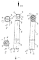
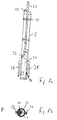
- Fig. 1 shows a schematic representation of the shaft of a Embodiment of the brush part according to the invention in Top view in the direction of the transverse bore
- Fig. 2 shows is a schematic representation of the shaft of the embodiment of the brush part according to the invention in plan view in Direction perpendicular to the transverse bore
- Fig. 2a a corresponding Top view in the direction of arrow D
- Fig. 2b a corresponding plan view in the direction of arrow E.
- 40 denote a shaft or a housing, 41 a annular recess for a bead 78 (see FIG. 3), 42 Holes, 43 a pin, 44 a snug fit for a bead 35 (cf. FIG. 4), 45 a groove and / or bore; 46 a transverse bore, 47 a front area, 48 a recess for a Flag 75 (see FIG. 3) and 49 a longitudinal bore.
- the shaft 40 used is a one-piece injection-molded housing part, which inside is that of the rear end Longitudinal bore 49 through to the front region 47 having.
- the annular groove 41 is provided in the rear area, which to lock a later to be described Clamping ring is used.
- the fit designated with 44 is used for locking with a corresponding bead, the one to be inserted into the shaft 40 Axis. At this point the cross section narrows the longitudinal bore.
- the fit 44 has a circular shape Edge, which locks the bead of the axis in guaranteed radial direction, with an axial rotation the axis remains unrestricted.
- transverse bore 46 Arranged essentially perpendicular to the longitudinal bore 49 is the transverse bore 46.
- the bottom region of the bore has the holes 42 so that toothpaste and water fill this area of the shaft 40 can rinse well and no residues remain, which could impair the function or could require nucleation.
- the cross hole 46 is used to accommodate the brush head to be described later.
- Pin 43 At the bottom of the transverse bore 46 is provided Pin 43, which in a corresponding bearing bush Brush head fits.
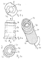
- FIG. 3 shows a schematic representation of the clamping ring the embodiment of the brush part according to the invention, and FIG. 3a in section, FIG. 3b a corresponding top view a corresponding in the direction of arrow I, Fig. 3c Top view in the direction of arrow J and Fig. 3d a corresponding perspective view.
- a clamping ring 71 an elastic ring-shaped and / or segmented molded part, 72 an interior or an inner bore, 73 a flat, 74 a bearing bush, 75 a flag and 78 a bead.
- FIG. 3 Shown in Figure 3 is the clamping ring 70, which in the The rear region of the shaft 40 can be inserted and locked there is.
- the radial circumferential bead is used for locking 78, which engages in the groove 41 of the shaft 40.
- Articulated on the back of the clamp ring are the two flags 75, which in corresponding recesses 48 of the shaft a form fit.
- the bearing bush 74 is provided in the rear end fits the axis described below.
- an elastic molded part 71 is provided on the clamping ring, which with the handle part head 30 one to be introduced there Handle part engages. Furthermore, the inner bore 72 a flattened portion 73, which has a positive fit a corresponding flattening of the head 30 sits so that mutual radial rotation is prevented.
- the flags 75 have a different from the rest of the clamping ring 70 Color on, so that when in use Shank 40 color-coded for different users is.
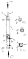
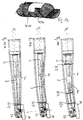
- Fig. 4 shows a schematic representation of the axis of the Embodiment of the brush part according to the invention
- Fig. 4a a corresponding plan view in the direction of arrow G
- Fig. 4b is a section in the direction of arrow A
- Fig. 4c a corresponding plan view in the direction of arrow F.
- the axis 3 shown in Figure 4 is also in this Example, a one-piece injection molded part, wherein however, for the elastic formations 33, 34 different plastic is used.
- the bead 35 locked in the inserted state in the snug fit 44 of the shaft 40, whereby a latched plain bearing is formed.
- the Racks 17 located at the front end act with corresponding ones Racks together, which will be described later Brush head are provided.
- axis 3 is provided with a recess or bore 31, in which a motor shaft of a corresponding handle part is importable.
- the recess 31 has a bevel in its front area 39, which corresponds to the transition of the motor shaft from corresponds to a full circle profile to a semicircle profile.
- the front of the motor shaft is therefore axially positive storable.
- the front ring 33 is provided such that it fits into the customary notch of the motor shaft 2 can intervene.
- the elasticity of the molded Parts differ from that of axis 3 in that than to allow flexible adjustment is bigger.
- axis 3 is essentially one has circular symmetry.
- the pin 37 is in one piece in this embodiment is made with the axis 3, it can be act a metal pin in the form of an insert, and for reasons of greater strength, because this pin 37 is intended to fix the brush head in the assembled state 80 cause in the axial direction of the transverse bore 46.
- Fig. 5 shows a schematic representation of the brush head the embodiment of the brush part according to the invention, 5a in a side view of the bridge, FIG. 5b in top view of the bridge and Fig. 5c in side view parallel to the bridge.
- a brush head Describe in addition to the elements already introduced 80 a brush head, 81 bristles, 82 a bearing bush for the pin 43, 83 stops, 84 a bridge part, 85 a hole for pin 37, 86 racks, 88 a groove and 89 a semicircular rib.
- the brush head 80 shown in Figure 5 has on it one side of bristles 81 with a corresponding one Glues are glued in the usual way or mechanically are woven in.
- a bridge part 84 is provided which has a hole 85 to carry out the pin 37 of the axis 3 in the assembled Condition forms.
- the stops 83 serve to limit the rotary movement and are formed in one piece with a rib 89, the one has semicircular shape.
- the stops 83 encounter in their end positions on the pin-like extension 87 of Axis 3.
- a bearing bushing 82 is provided on the top of the bridge 84, into which the pin 43 of the front part 47 of the shaft 40 engages.
- the racks 86 act with the racks 17 of the axis 3 together.
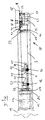
- Fig. 6 shows a schematic representation of the assembled State of the embodiment of the invention Brush part, placed on a corresponding handle part.
- the brush head 80 is in the front area 47 of the shaft 40 inserted and via the groove 88 with the Lock the upper edge area, not shown. So that's the Head 80 rotatably mounted in a slide bearing in the front area.
- axis 3 is from the rear end of the Shaft 40 inserted so that the bead 35 is snug 44 locked and the pin 37 through the hole 85 of the bridge part 84 runs to the groove 45.
- the two stops 83 are now end positions for the rotation of the brush head 80 in the front area 47 of the shaft 40 defined.
- the two racks 17 in the front area of axis 3 in engagement with the two Racks 86, which are integrated in the head. So it will Rotary movement of axis 3 in a perpendicular rotational movement of the head 80 transmitted.
- The is introduced into the rear region of the shaft 40 Clamping ring 70.
- the rear end of axis 3 gets into the Bearing bush 74 of the clamping ring and is also rotatable there stored.
- the head of the grip part 30 together with the one protruding therefrom motor-driven shaft 2 is then in the clamping ring 70 introduced, the orientation by flattening 73 of the clamping ring is specified.
- the motor shaft gets caught 2 in the recess 31 of the axis 3 and is from the elastic Ring inserts 33, 34 held in the axial direction.
- the semicircular profile lies above the bevel 39 Area of shaft 2 form-fitting on the Recess, so that an exact transmission of the rotary movement on axis 3 is guaranteed.
- the front ring 33 engages into the notch 22 of the shaft 2.
- This structure enables an adaptation of different Thicknesses and lengths of the motor shaft as well as various geometric To form.
- the head 30 of the handle part is additional against axial displacement due to the elastic ring 71 fixed.
- FIG. 7 shows a greatly enlarged schematic illustration the brush head of the embodiment of the invention Brush part, namely Fig. 7a in side view the bridge and Fig. 7b a simplified representation Illustration of the effectiveness of the roughened surface of the plain bearing.
- the roughened surfaces protruding elements especially teeth or bulges, have, which are arranged regularly.
- the order the above elements is designed such that the frequency of the pendulum movements in the ultrasonic range lies.
- the roughening can also or instead in the area 90 in Fig. 7a, namely on the bearing bush for the pin 43.
- FIG. 8 is a schematic representation of the axis of a another embodiment of the brush part according to the invention, 8a a side view and FIG. 8b a corresponding top view in the direction of arrow O.
- the plug is on the motor shaft 2 relieved. Namely, it can in the above embodiment occur that the brush head 80 to attach must be rotated relative to the motor axis 2, since the Chamfer 21 does not exactly match chamfer 39.
- the axis 3 has on the side two opposite, one-sided wings 38.
- Fig. 9 is a schematic representation of the clamping ring a further embodiment of the brush part according to the invention, 9a in section, Fig. 3b a corresponding Top view in the direction of arrow P and Fig. 9c a corresponding perspective view.
- FIGS. 10a to 10h show embodiments of the invention Brush part shown with such a bend.
- the brush head 80 according to Figure 10a and b with the front part 47 was angled overall, while according to Figure 10c only the head 80 was angled with the bristles. After figure 10d, the shape of the shaft 40 was bent like a banana.
- the shaft 40 has in the transition area to the Front part 47 an elastic region 200, which makes it possible that the front part 47 with the brush head 80 through the contact pressure can be angled into different positions.
- Figure 10f is between the shaft 40 and the front part 47 a uniaxial ball joint 250 instead of the elastic Area 200 provided.
- Figure 10g is the brush part shown rotated by 90 ° from FIG. 10f.
- the brush part according to FIG. 10d is on the side shown with a ball joint 250 rotatable in any direction.
- the same function could also be achieved by appropriate Design of the brush part according to Figure 10e can be achieved.
- FIG. 11a corresponds to the brush head according to FIG. 10c
- the representation according to FIG. 11b the brush head according to FIG. 10d
- the representation according to FIG. 11c Brush head according to Figure 10d with a more banana-shaped bend and one-piece axle, soak in the front area has single or multiple universal joint 400.
- FIG 12 shows a detailed representation of the universal joint 400.
- This universal joint 400 is made of a cylindrical Base body made, which parallel, twisted arranged Has slots 450.
- the slot area can be one different number of slots with different Have depth. Several slot areas arranged one behind the other, result in a greater angle adjustment option or a lower material bending stress of the gimbal area 400.
- the angular movements of the brush front part can thus without difficulty for the shaft 2 of the drive of the electrical Toothbrush can be traced.
- the universal joint 400 which consists of the multi-offset slotted angular area is the same as Axis misalignment due to bending.
- the bend takes place in the individual slots 450 and / or the cylindrical regions instead, being the material stretch, which is a bending without permanent deformation, must not be exceeded may.
- Suitable plastics are on the market known, e.g. Polypropylene.
- the elastic region 200 not shown in FIG. 11c, was measured Figure 10e is conveniently arranged so that the Universal joint 400 sits in its center. The axis compensation can thus easily go to one or more pages through the Cardan joint 400.
- the universal joint consisting of a cylindrical body is twisted through the parallel slots, however arranged are formed.
- the slot depth is included material-related.
- the slot bottom becomes very careful be rounded to prevent stress cracks.
- the central pin 37 is aligned the axis 3, which holds the head 80, not.
- This axis offset causes both pin 37 and head 80 in the hole area 85 are more heavily loaded.
- This axis offset but is according to the life of the brush heads tolerable.
- the axis offset can be by Avoid universal joint 400.
- Alternatively to the one-piece Axis 3 with the cardan joint 400 would also be possible multi-part axle with single or multi-part universal joint train.
- the clamping ring is not at the end of the shaft absolutely necessary, but a molded in the shaft elastic part could take over its function. In this case it is advisable to face the shaft End the axle with little play in the longitudinal bore.
- the axle snaps into the Fits in the shaft and is axially fixed.
- To the plain bearing can improve the bead of the axle from a Be made of material that is different from the base material the axis differs.
- the pen-like extension the axis through a hole from the face of the cross hole can be inserted through the bridge and into the axis.
- This type of import is known per se, but is used in State of the art only used to set a stop.
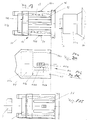
- FIG. 13 shows a schematic illustration of the clamping plug 70 of the brush part 10 with latching clamping means which are attached at the top and bottom and act in the radial direction in contact with the inner edge of the recess 41a with the grip piece 30, metal axis 2 and housing pin 30a;
- 70 denote a clamping plug, 71 deforming annular or segmented clamping means, 72 an interior space, 72b an incline, 72c a bead or groove, 74 a bearing bush, 76 an annular extension, 77 one or more recesses or slots, 78 a bead
- FIG. 14 shows a schematic illustration of the housing 40 of the preferred embodiment of the brush part according to the invention in FIG. 2a in a vertical section and in FIG. 2b in a horizontal section; 40 designate a shaft or housing, 41 a widened, annular recess for a bead 78 (see FIG. 1), 41a deforming, annular or segmented clamping means, 42b a bevel, 42c a groove or bead, 49 a longitudinal bore
- FIG. 15 shows a schematic illustration of the clamping plug 70 of the brush part 10 with the Clamping means 71 in plan view offset to the right up to the inner edge of the recess 41b Housing sleeve 40, 3 an axis of the brush part 10.
- the clamping plug 70 is inserted into the housing 40.
- the clamping plug 70 is slidable within the widened, annular recess 41 between the inner edges 41a and 41b. If the clamping plug 70 is with its bead edge 78b on the inner edge 41b of the housing 40, the clamping means 71 and 41a are not in engagement.
- the inner space 72 is thus open and the clamping plug 70 can easily be pushed on or pulled off from or onto the housing 30 or the housing pin 30a. If the clamping plug 70 stands with its bead edge 78a on the inner edge 41a of the housing 40, the clamping means 71 and 41a are in engagement.
- the interior 72 is thus clamped and reduced in size, and the clamping plug 70 can only be pushed on or pulled off from or onto the housing 30 or the housing pin 30a under the action of force.
- the clamping means 41a, 71 it is possible to precisely adjust the pulling force of the brush part 10 from the handle 30, 30a.
- the bevels 42b of the housing 40 and the bevels 72b of the clamping plug 70 are matched in such a way that the clamping plug 70 is easily displaceable in the recess 41 within the housing 70 and the interior 72 is reduced when the clamping plug 70 is inserted into the housing 40, thus reducing the size the brush part 10 is clamped on the housing 30, 30a.
- the housing 40 is provided on the clamping means 41a and the clamping plug 70 on the clamping means 71 has a groove or corresponding bead 42c and 72c, which at Installation of the inner edge 41 a on the bead edge 78 a locking the housing 40 against the Effect clamping plug 70.
- the brush part can be easily pulled off the handle part by adjusting the resistance of the Locking of tongue and groove 42c and 72c is overcome by pulling on the brush part, the housing 40 of subtracts the housing 30, 30a and thus removes the clamping by the clamping means 41a and 71.
- the clamping plug 70 can receive one or more ribs or segments 79 in the interior 72 for better clamping on the housing 30,30a.
- Analogous to oscillating axes there are those with lifting and / or oscillating movements.
- To the oscillating To achieve movement of the preferred embodiment can be a corresponding adapter that is identical the housing 30, 30a is fastened and in turn the brush part 10 with corresponding fastening its housing, which corresponds to the housing 30,30a, are used.
- the Clamping plug 70 Against an unintentional rotation of the clamping plug 70 in the bore 49 of the housing 40, the Clamping plug 70 one or more ribs 70a, which in corresponding recesses 40a of the housing 40 in the hole 49 engage.
Abstract
Description
Die vorliegende Erfindung betrifft ein Bürstenteil für eine elektrische Zahnbürste mit einem mit einem Griffteil verbindbaren Schaft, welcher eine Längsbohrung und eine Querbohrung aufweist; einer mit einer Welle des "Griffteils verbindbaren Achse, welche in der Längsbohrung drehfähig aufnehmbar ist; einem Bürstenkopf, welcher in der Querbohrung drehfähig aufnehmbar ist; Übertragungsmitteln zum Übertragen der Drehbewegung der Achse auf den Bürstenkopf.The present invention relates to a brush part for a electric toothbrush with a connectable with a handle Shank, which has a longitudinal bore and a transverse bore having; one connectable with a shaft of the "handle part Axis, which can be rotatably received in the longitudinal bore is; a brush head, which is in the cross hole is rotatably mountable; Transmission means for transmission the rotational movement of the axis on the brush head.
Solche Bürstenteile für elektrische Zahnbürsten werden heutzutage in großer Vielzahl auf dem Markt angeboten. Die bekannten Bürstenteile sind dabei speziell jeweiligen Griffteilen zugeordnet und angepaßt. Damit ergibt sich, daß die von den verschiedenen Herstellern gefertigten Bürstenteile nicht untereinander austauschbar sind, sondern jeweils nur zu einem speziellen Griffteil passen.Such brush parts for electric toothbrushes offered in large numbers on the market today. The known brush parts are specifically respective Handle parts assigned and adjusted. This means that the brush parts manufactured by the various manufacturers are not interchangeable, but each only fit to a special handle part.
Die marktüblichen Bürstenteile bestehen aus mehreren unterschiedlichen Einzelteilen, welche aus verschiedenen Materialien gefertigt sind. Insbesondere findet man in der Regel Spritzgußteile und Metallteile. Diese Teilevielfalt erhöht einerseits die Herstellungskosten und kompliziert den Zusammenbau. Außerdem sind die bekannten Bürstenteile derart gestaltet, daß sie bei Defekt eines Bestandteils nicht repariert werden können, sondern als Ganzes ausgetauscht werden müssen.The usual brush parts consist of several different ones Individual parts, which are made of different materials are made. In particular, one usually finds Injection molded parts and metal parts. This variety of parts increases on the one hand the manufacturing costs and complicates the Assembly. In addition, the known brush parts are such designed that they do not defective one component can be repaired, but replaced as a whole Need to become.
Zahnbürsten haben weiterhin die Eigenschaft. in ihren Feuchtraumen das Wachsen von Keimen zu begünstigen. Um dem zu begegnen, setzt man im Bereich der Borsten oligodynamische Materialien ein, und zwar ublicherweise in Form von galvanischen Überzügen oder Klemmitteln.Toothbrushes still have the property. in your Damp areas favor the growth of germs. To that to counteract, one sets in the area of the bristles oligodynamic Materials, usually in the form of galvanic coatings or clamping means.
Aus der DE 39 37 853 A1 ist eine elektrische Zahnbürste bekannt, welche ein Griffteil mit einem elektromotorischen Antrieb und einer Antriebswelle sowie ein Bürstenteil mit einer in einem Gehäuse bzw. Schaft gelagerten Achse aufweist, wobei das Bürstenteil mit dem Griffteil über Kupplungsmittel zur Festlegung des Bürstenteils am Griffteil und zur Kopplung der Antriebswelle mit der Achse verbindbar ist.An electric toothbrush is known from DE 39 37 853 A1, which is a handle part with an electromotive Drive and a drive shaft and a brush part with has an axle mounted in a housing or shaft, the brush part with the handle part via coupling means for fixing the brush part on the handle part and connectable for coupling the drive shaft to the axis is.
Insbesondere offenbart die DE 3937853 A1 eine Festlegung das Bürstenteils am Griffteil in axialer und radialer Richtung jeweils durch separate Kupplungsmittel, wobei einerseits Kupplungsmittel der Antriebswelle und der Achse und andererseits Kupplungsmittel des Schaftes des Bürstenteils und des Griffteils zusammenwirken. Die Axialsicherung erfolgt mittels Rastmittel der Achse, welche in ein Widerlager der Antriebswelle eingreifen. Die Radialsicherung erfolgt über ein bestimmtes Profil von Schaft und Kopf des Griffteils.In particular, DE 3937853 A1 discloses a definition the brush part on the handle part in the axial and radial direction each by separate coupling means, one hand Coupling means of the drive shaft and the axle and on the other hand coupling means of the shaft of the brush part and the handle part interact. The axial locking takes place by means of locking means of the axis, which in an abutment engage the drive shaft. The radial locking takes place about a specific profile of the shaft and head of the Handle part.
Aus der DE 33 46 758 A1 ist es bekannt, eine Kegelradverbindung bzw. Zahnszangenverbindung zwischen dem Bürstenkopf und der Achse des Bürstenteils vorzusehen. From DE 33 46 758 A1 it is known a bevel gear connection or forceps connection between the brush head and to provide the axis of the brush part.
Marktüblich sind auch komplizierte Kippstangen-Konstruktionen zur Übertragung der Drehbewegung der Achse auf den Bürstenkopf. Diese Konstruktionen sind nicht nur schwer zusammenfügbar, sondern weisen auch viele Einzelteile auf.Complicated rocker bar constructions are also common on the market to transfer the rotary motion of the axis to the Brush head. These constructions are not only difficult to assemble, but also have many individual parts.
Ein weiterer Nachteil der bekannten Bürstenkopfe liegt darin, daß der Zahnbelag mit Hilfe von rotierenden Borsten nur schwer entfernbar ist.Another disadvantage of the known brush heads is that that the plaque with the help of rotating bristles only is difficult to remove.
Eine Aufgabe der vorliegenden Erfindung besteht darin, ein vereinfachtes Bürstenteil für eine elektrische Zahnbürste zu schaffen, welches in einem vereinfachten Fertigungsprozeß zusammengebaut werden kann und welches eine verbesserte Reinigungswirkung aufweist.An object of the present invention is to provide a simplified brush part for an electric toothbrush to create which in a simplified manufacturing process can be assembled and which one is improved Has cleaning effect.
Insbesondere soll die Anzahl der Einzelteile verringert werden. Weiterhin soll ein Bürstenteil geschaffen werden, das auf verschiedenen Griffteilen unterschiedlicher Hersteller ohne einen zusätzlichen Adapter befestigbar ist. In particular, the number of individual parts should be reduced become. Furthermore, a brush part is to be created on different handle parts from different manufacturers can be attached without an additional adapter.
Die Erfindung schafft ein Bürstenteil nach Anspruch 1.The invention provides a brush part according to claim 1.
Eine der vorliegenden Erfindung zugrundeliegende Idee besteht darin, daß der Bürstenkopf in der Querbohrung mittels eines verrastbaren Gleitlagers gelagert ist, welches eine entsprechende axiale Fixierung bewirkt, wobei das Gleitlager eine derart aufgerauhte Oberflache aufweist, daß eine axiale Pendelbewegung ermöglicht ist.One idea on which the present invention is based exists in that the brush head in the cross hole by means a lockable plain bearing is mounted, which a corresponding axial fixation causes, the plain bearing has such a roughened surface that a axial pendulum movement is enabled.
Ein wesentlicher Vorteil des erfindungsgemäßen Bürstenteils besteht darin, daß die Anzahl der Einzelteile durch Integration verringert ist. Die Verwendung eines oder mehrerer rastbarer Gleitlager vereinfacht den Zusammenbau. Die Entfernung des Zahnbelags wird durch die axiale Pendelbewegung, welche der radialen Bewegung des Bürstenkopfes überlagert ist, wirksam unterstützt. Die Borsten werden somit in eine auf den Zahnbelag stoßende Bewegung versetzt, wodurch der Zahnbelag aufgerissen wird und leichter entfernbar ist.A major advantage of the brush part according to the invention is that the number of parts through integration is reduced. The use of one or more Lockable slide bearing simplifies assembly. The distance of the plaque is due to the axial pendulum movement, which overlaps the radial movement of the brush head is effectively supported. The bristles are thus set in a movement on the dental plaque, whereby the plaque is torn open and easier to remove is.
Weiterhin können die Bestandteile des erfindungsgemäßen Bürstenteils austauschbar gestaltet werden, so daß beispielsweise der Bürstenkopf ersetzbar ist, ohne daß das gesamte Bürstenteil ausgetauscht werden muß.Furthermore, the components of the invention Brush part can be designed interchangeably, so that for example the brush head can be replaced without the whole Brush part must be replaced.
In den Unteransprüchen finden sich vorteilhafte Weiterbildungen und Verbesserungen des in Anspruch 1 angegebenen Bürstenteils. Advantageous further developments can be found in the subclaims and improvements to that specified in claim 1 Brush part.
Eine weitere Idee der vorliegenden Erfindung besteht darin, das Bürstenteil mittels einer
hohlen Achse klemmend über die Antriebswelle des Griffteils zu schieben und in axialer
Richtung mittels eines in axialer Richtung verschiebbaren, über Rastelemente verformbaren
Klemmstopfen auf einem vorstehenden Gehäuse oder Gehäuseteil festzuklemmen.
Die Rotationsbewegungen der Metallachse des Griffteils werden durch die Klemmung der
Bürstenachse übertragen, die radiale und axiale Festlegung des Bürstenteils wird durch die
Festklemmung mittels des elastischen, verfornbaren Stopfen erreicht.
Damit entfallen sonst notwendige Kupplungsmittel zwischen Metallachse des Griffteils und
Achse des Bürstenteils.
Ein Vorteil dieser Erfindung ist, dass bei einem notwendigen Austausch des Bürstenteils der
Verbraucher nur Einzelteile wechselt und nicht das gesamte Bürstenteil wechseln muss. Another idea of the present invention is to push the brush part by means of a hollow axis, clampingly over the drive shaft of the handle part, and to clamp it in the axial direction on a projecting housing or housing part by means of a clamping plug which can be displaced in the axial direction and deformable by latching elements.
The rotational movements of the metal axis of the handle part are transmitted by the clamping of the brush axis, the radial and axial fixing of the brush part is achieved by clamping by means of the elastic, deformable plug.
This eliminates the otherwise necessary coupling means between the metal axis of the handle part and the axis of the brush part.
An advantage of this invention is that when the brush part needs to be replaced, the consumer only changes individual parts and does not have to change the entire brush part.
Ausführungsbeispiele der Erfindung sind in den Zeichnungen dargestellt und in der nachfolgenden Beschreibung naher erläutert.Embodiments of the invention are in the drawings shown and explained in more detail in the following description.
Es zeigen:
- Fig. 1
- eine schematische Darstellung des Schafts einer Ausführungsform des erfindungsgemäßen Bürstenteils in Draufsicht in Richtung der Querbohrung;
- Fig. 2
- eine schematische Darstellung des Schafts der Ausführungsform des erfindungsgemäßen Bürstenteils in Draufsicht in Richtung senkrecht zu der Querbohrung, Fig. 2a eine entsprechende Draufsicht in Richtung des Pfeils D und Fig. 2b eine entsprechende Draufsicht in Richtung des Pfeils E;
- Fig. 3
- eine schematische Darstellung des Klemmringes der Ausführungsform des erfindungsgemäßen Bürstenteils, und zwar Fig. 3a im Schnitt, Fig. 3b eine entsprechende Draufsicht in Richtung des Pfeils I, Fig. 3c eine entsprechende Draufsicht in Richtung des Pfeils J und Fig. 3d eine entsprechende perspektivische Ansicht;
- Fig. 4
- eine schematische Darstellung der Achse der Ausführungsform des erfindungsgemäßen Bürstenteils, Fig. 4a eine entsprechende Draufsicht in Richtung des Pfeils G, Fig. 4b ein Schnitt in Richtung des Pfeils A und Fig. 4c eine entsprechende Draufsieht in Richtung des. Pfeils F;
- Fig. 5
- eine schematische Darstellung des Bürstenkopfes der Ausführungsform des erfindungsgemäßen Bürstenteils, und zwar Fig. 5a in Seitenansicht auf die Brücke, Fig. 5b in Oberansicht auf die Brücke und Fig. 5c in Seitenansicht parallel zur Brücke;
- Fig. 6
- eine schematische Darstellung des zusammengebauten Zustandes der Ausführungsform des erfindungsgemäßen Bürstenteils, aufgesetzt auf ein entsprechendes Griffteil;
- Fig. 7
- eine stark vergrößerte schematische Darstellung des Bürstenkopfes der Ausführungsform des erfindungsgemäßen Bürstenteils, und zwar Fig. 7a in Seitenansicht auf die Brücke und Fig. 7b eine vereinfachte Darstellung zur Illustration der Wirksamkeit der aufgerauhten Oberflache des Gleitlagers;
- Fig. 8
- eine schematische Darstellung der Achse einer weiteren Ausführungsform des erfindungsgemäßen Bürstenteils, und zwar Fig. 8a eine Seitenansicht und Fig. 8b eine entsprechende Draufsicht in Richtung des Pfeils O;
- Fig. 9
- eine schematische Darstellung des Klemmringes einer weiteren Ausführungsform des erfindungsgemäßen Bürstenteils, und zwar Fig. 9a im Schnitt, Fig. 9b eine entsprechende Draufsicht in Richtung des Pfeils P und Fig. 9c eine entsprechende perspektivische Ansicht;
- Fig. 10a-h
- Beispiele für verschiedene Bürstenteil-Formen;
- Fig. 11a-c
- eine schematische Darstellung des zusammengebauten Zustandes einer weiteren Ausführungsform des erfindungsgemäßen Bürstenteils; und
- Fig. 12
- eine Draufsicht auf das Kardangelenk nach Fig. 11c.
- Fig. 13
- eine schematische Darstellung des Klemmstopfens des Bürstenteils mit oben und unten angelängten rastenden Klemmitteln und Rippen, die in radialer Richtung wirken;
- Fig. 14
- eine schematische Darstellung der Gehäusehülse der Ausführungsform des erfindungsgemäßen
Bürstenteils im Schnitt,
Fig. 2a einen senkrecht Schnitt und
Fig. 2b einen waagrechten Schnitt zum Klemmstopfen; - Fig. 15
- eine schematische Darstellung des Klemmstopfens des Bürstenteils mit den angelängten rastenden Klemmmmitteln in Draufsicht versetzt nach rechts bis zur Innenkante der Aussparung der Gehäusehülse.,
- Fig. 1
- a schematic representation of the shaft of an embodiment of the brush part according to the invention in plan view in the direction of the transverse bore;
- Fig. 2
- a schematic representation of the shaft of the embodiment of the brush part according to the invention in plan view in the direction perpendicular to the transverse bore, FIG. 2a a corresponding plan view in the direction of arrow D and FIG. 2b a corresponding plan view in the direction of arrow E;
- Fig. 3
- a schematic representation of the clamping ring of the embodiment of the brush part according to the invention, namely Fig. 3a in section, Fig. 3b a corresponding top view in the direction of arrow I, Fig. 3c a corresponding top view in the direction of arrow J and Fig. 3d a corresponding perspective view ;
- Fig. 4
- 4a shows a corresponding plan view in the direction of arrow G, FIG. 4b shows a section in the direction of arrow A and FIG. 4c shows a corresponding top view in the direction of arrow F;
- Fig. 5
- a schematic representation of the brush head of the embodiment of the brush part according to the invention, namely FIG. 5a in side view of the bridge, FIG. 5b in top view of the bridge and FIG. 5c in side view parallel to the bridge;
- Fig. 6
- a schematic representation of the assembled state of the embodiment of the brush part according to the invention, placed on a corresponding handle part;
- Fig. 7
- a greatly enlarged schematic representation of the brush head of the embodiment of the brush part according to the invention, namely Fig. 7a in side view of the bridge and Fig. 7b a simplified representation to illustrate the effectiveness of the roughened surface of the plain bearing;
- Fig. 8
- a schematic representation of the axis of a further embodiment of the brush part according to the invention, namely FIG. 8a a side view and FIG. 8b a corresponding top view in the direction of arrow O;
- Fig. 9
- a schematic representation of the clamping ring of a further embodiment of the brush part according to the invention, namely FIG. 9a in section, FIG. 9b a corresponding top view in the direction of arrow P and FIG. 9c a corresponding perspective view;
- 10a-h
- Examples of different brush part shapes;
- Figures 11a-c
- a schematic representation of the assembled state of a further embodiment of the brush part according to the invention; and
- Fig. 12
- a plan view of the universal joint according to Fig. 11c.
- Fig. 13
- is a schematic representation of the clamping plug of the brush part with locking clips and ribs at the top and bottom, which act in the radial direction;
- Fig. 14
- 2 shows a schematic illustration of the housing sleeve of the embodiment of the brush part according to the invention in section,
Fig. 2a is a vertical section and
2b shows a horizontal section for the clamping plug; - Fig. 15
- is a schematic representation of the clamping plug of the brush part with the extended locking means in plan view offset to the right up to the inner edge of the recess of the housing sleeve.
In den Figuren bezeichnen gleiche Bezugszeichen gleiche oder funktionsgleiche Elemente.In the figures, the same reference symbols designate the same or functionally equivalent elements.
Fig. 1 zeigt eine schematische Darstellung des Schafts einer Ausführungsform des erfindungsgemäßen Bürstenteils in Draufsicht in Richtung der Querbohrung, und Fig. 2 zeigt eine schematische Darstellung des Schafts der Ausführungsform des erfindungsgemäßen Bürstenteils in Draufsicht in Richtung senkrecht zu der Querbohrung, Fig. 2a eine entsprechende Draufsicht in Richtung des Pfeils D und Fig. 2b eine entsprechende Draufsicht in Richtung des Pfeils E.Fig. 1 shows a schematic representation of the shaft of a Embodiment of the brush part according to the invention in Top view in the direction of the transverse bore, and Fig. 2 shows is a schematic representation of the shaft of the embodiment of the brush part according to the invention in plan view in Direction perpendicular to the transverse bore, Fig. 2a a corresponding Top view in the direction of arrow D and Fig. 2b a corresponding plan view in the direction of arrow E.
Es bezeichnen 40 einen Schaft bzw. ein Gehäuse, 41 eine ringförmige Aussparung für eine Wulst 78 (vgl. Fig. 3), 42 Löcher, 43 einen Stift, 44 einen Paßsitz für eine Wulst 35 (vgl. Fig. 4), 45 eine Nut und/oder- Bohrung; 46 eine Querbohrung, 47 einen Vorderbereich, 48 eine Ausnehmung für eine Fahne 75 (vgl Fig. 3) und 49 eine Längebohrung.40 denote a shaft or a housing, 41 a annular recess for a bead 78 (see FIG. 3), 42 Holes, 43 a pin, 44 a snug fit for a bead 35 (cf. FIG. 4), 45 a groove and / or bore; 46 a transverse bore, 47 a front area, 48 a recess for a Flag 75 (see FIG. 3) and 49 a longitudinal bore.
Der bei dieser Ausführungsform des erfindungsgemäßen Bürstenteils
verwendete Schaft 40 ist ein einteiliges Spritzguß-Gehauseteil,
welches in seinem Inneren die vom Hinterende
bis zum Vorderbereich 47 durchgehende Längsbohrung 49
aufweist. Im Hinterbereich ist die ringförmige Nut 41 vorgesehen,
welche zur Verrastung eines später zu beschreibenden
Klemmrings verwendet wird. The in this embodiment of the brush part according to the invention
the
Der mit 44 bezeichnete Paßsitz dient zur Verrastung mit einer
entsprechenden Wulst, der in den Schaft 40 einzufuhrenden
Achse. An dieser Stelle verengt sich der Querschnitt
der Längsbohrung. Der Paßsitz 44 hat einen kreisformig verlaufenden
Rand, was eine Verrastung der Wulst der Achse in
radialer Richtung gewährleistet, wobei eine axiale Drehung
der Achse uneingeschrankt möglich bleibt.The fit designated with 44 is used for locking with a
corresponding bead, the one to be inserted into the
Im wesentlichen senkrecht zur Langsbohrung 49 angeordnet
ist die Querbohrung 46. Der Bodenbereich der Bohrung weist
die Löcher 42 auf, damit Zahnpasta und Wasser diesen Bereich
des Schaftes 40 gut spülen können und keine Rückstände
zurückbleiben, welche die Funktion beeinträchtigen konnten
oder die Keimbildung fordern konnten. Die Querbohrung
46 dient zur Aufnahme des später zu beschreibenden Bürstenkopfes.
Am Boden der Querbohrung 46 vorgesehen ist der
Stift 43, welcher in eine entsprechende Lagerbuchse des
Bürstenkopfes paßt.Arranged essentially perpendicular to the
Eingearbeitet in den Vorderbereich 47 des Schaftes 40 in
die Wand der Querbohrung 46 ist weiterhin die Nut 45, welche
zur Aufnahme einer stiftartigen Verlängerung der Achse
dient.Machined into the
Fig. 3 zeigt eine schematische Darstellung des Klemmringes der Ausführungsform des erfindungsgemäßen Bürstenteils, und zwar Fig. 3a im Schnitt, Fig. 3b eine entsprechende Draufsicht in Richtung des Pfeils I, Fig. 3c eine entsprechende Draufsicht in Richtung des Pfeils J und Fig. 3d eine entsprechende perspektivische Ansicht.Fig. 3 shows a schematic representation of the clamping ring the embodiment of the brush part according to the invention, and FIG. 3a in section, FIG. 3b a corresponding top view a corresponding in the direction of arrow I, Fig. 3c Top view in the direction of arrow J and Fig. 3d a corresponding perspective view.
Zusätzlich zu den bereits eingeführten Elementen bezeichnen 70 einen Klemmring, 71 ein elastisches ringförmiges und/oder segmentiertes Anformungsteil, 72 einen Innenraum bzw. eine Innenbohrung, 73 eine Abflachung, 74 eine Lagerbuchse, 75 eine Fahne und 78 eine Wulst.Describe in addition to the elements already introduced 70 a clamping ring, 71 an elastic ring-shaped and / or segmented molded part, 72 an interior or an inner bore, 73 a flat, 74 a bearing bush, 75 a flag and 78 a bead.
Dargestellt in Figur 3 ist der Klemmring 70, welcher in den
Hinterbereich des Schaftes 40 einführbar und dort verrastbar
ist. Zur Verrastung dient die radial umlaufende Wulst
78, welche in die Nut 41 des Schaftes 40 eingreift. Angelenkt
an der Hinterseite des Klemmrings sind die zwei Fahnen
75, welche in entsprechende Ausnehmungen 48 des Schaftes
formschlussig passen. Auf der Vorderseite des Klemmrings
70 ist die Lagerbuchse 74 vorgesehen, in die das Hinterende
der weiter unten beschriebenen Achse paßt.Shown in Figure 3 is the clamping
Wie aus Figur 3a ersichtlich, ist im hohlen Innenraum 72
des Klemmrings ein elastisches Anformteil 71 vorgesehen,
welches mit dem Griffteil-Kopf 30 eines dort einzuführenden
Griffteils in Eingriff tritt. Des weiteren weist die Innenbohrung
72 eine Abflachung 73 auf, welche formschlüssig auf
einer entsprechenden Abflachung des Kopfes 30 sitzt, so daß
eine gegenseitige radiale Verdrehung verhindert ist.As can be seen from FIG. 3a, 72 is in the hollow interior
an elastic molded
Die Fahnen 75 weisen eine vom Rest des Klemmrings 70 abweichende
Farbe auf, so daß im eingesetzten Zustand der
Schaft 40 farblich für unterschiedliche Benutzer gekennzeichnet
ist.The
Fig. 4 zeigt eine schematische Darstellung der Achse der Ausführungsform des erfindungsgemäßen Bürstenteils, Fig. 4a eine entsprechende Draufsicht in Richtung des Pfeils G, Fig. 4b ein Schnitt in Richtung des Pfeils A und Fig. 4c eine entsprechende Draufsicht in Richtung des Pfeils F.Fig. 4 shows a schematic representation of the axis of the Embodiment of the brush part according to the invention, Fig. 4a a corresponding plan view in the direction of arrow G, Fig. 4b is a section in the direction of arrow A and Fig. 4c a corresponding plan view in the direction of arrow F.
Zusätzlich zu den bereits eingeführten Elementen bezeichnen 3 eine Achse, 33 und 34 ein elastisches Anformteil in Form zweier Klemmringe und/oder Klemmsegmente, 35 eine Wulst, 37 einen Stift, 17 Zahnstangen, 31 eine Ausnehmung und 39 eine Anschrägung.Describe in addition to the elements already introduced 3 an axis, 33 and 34 an elastic molded part in shape two clamping rings and / or clamping segments, 35 a bead, 37 a pin, 17 racks, 31 a recess and 39 a Bevel.
Die in Figur 4 dargestellte Achse 3 ist ebenfalls bei diesem
Beispiel ein einteilig hergestelltes Spritzgußteil, wobei
allerdings für die elastischen Anformungen 33, 34 ein
unterschiedlicher Kunststoff verwendet wird. Die Wulst 35
verrastet im eingeführten Zustand im Paßsitz 44 des Schafts
40, wodurch ein verrastetes Gleitlager gebildet wird. Die
am Vorderende befindlichen Zahnstangen 17 wirken mit entsprechenden
Zahnstangen zusammen, welche am später zu beschreibenden
Bürstenkopf vorgesehen sind. Im Hinterbereich
der Achse 3 ist eine Ausnehmung bzw. Bohrung 31 vorgesehen,
in welche eine Motorwelle eines entsprechenden Griffteils
einfuhrbar ist. The
Die Ausnehmung 31 weist in ihrem Vorderbereich eine Anschrägung
39 auf, welche dem Übergang der Motorwelle von
einem Vollkreisprofil zu einem Halbkreisprofil entspricht.
Somit ist die Motorwelle in ihrem Vorderbereich axial formschlussig
lagerbar. Angeformt im Hinterbereich der Achse,
nämlich in einem zweikomponentigen Spritzgußverfahren, sind
elastische Ringe 33, 34, welche eine elastische Klemmwirkung
auf die Motorwelle ausüben, so daß eine axiale Fixierung
ermöglicht ist. Insbesondere der vordere Ring 33 ist
derart vorgesehen, daß er in die marktübliche Kerbe der Motorwelle
2 eingreifen kann. Die Elastizität der angeformten
Teile unterscheidet sich von derjenigen der Achse 3 insofern,
als daß sie zur Ermöglichung einer flexiblen Anpassung
größer ist.The
In axialer Richtung betrachtet, nämlich von Punkt F oder
Punkt G, läßt sich erkennen, daß die Achse 3 eine im wesentlichen
kreisformige Symmetrie aufweist.Viewed in the axial direction, namely from point F or
Point G, it can be seen that
Obwohl der Stift 37 bei diesem Ausführungsbeispiel einteilig
mit der Achse 3 hergestellt ist, kann es sich dabei um
einen Metallstift in Form eines Einsetzteils handeln, und
zwar aus Gründen der größeren Festigkeit, denn dieser Stift
37 soll im zusammengebauten Zustand eine Fixierung des Bürstenkopfes
80 in Axialrichtung der Querbohrung 46 bewirken.Although the
Fig. 5 zeigt eine schematische Darstellung des Bürstenkopfes der Ausführungsform des erfindungsgemäßen Bürstenteils, und zwar Fig. 5a in Seitenansicht auf die Brücke, Fig. 5b in Oberansicht auf die Brücke und Fig. 5c in Seitenansicht parallel zur Brücke. Fig. 5 shows a schematic representation of the brush head the embodiment of the brush part according to the invention, 5a in a side view of the bridge, FIG. 5b in top view of the bridge and Fig. 5c in side view parallel to the bridge.
Zusätzlich zu den bereits eingeführten Elementen bezeichnen
80 eine Bürstenkopf, 81 Borsten, 82 eine Lagerbuchse für
den Stift 43, 83 Anschlage, 84 ein Brückenteil, 85 ein Loch
für den Stift 37, 86 Zahnstangen, 88 eine Nut und 89 eine
halbkreisförmige Rippe.Describe in addition to the elements already introduced
80 a brush head, 81 bristles, 82 a bearing bush for
the
Der in Figur 5 dargestellte Bürstenkopf 80 weist an seiner
einen Seite Borsten 81 auf, die mit einem entsprechenden
Kleber in ublicher Art und Weise eingeklebt sind bzw. mechanisch
eingeflochten sind.The
An der den Borsten 81 abgewandten Seite des Bürstenkopfes
80 ist ein Brückenteil 84 vorgesehen, welches ein Loch 85
zur Durchführung des Stiftes 37 der Achse 3 im zusammengebauten
Zustand bildet.On the side of the brush head facing away from the bristles 81
80 a
Die Anschläge 83 dienen zur Begrenzung der Drehbewegung und
sind einteilig mit einer Rippe 89 ausgebildet, die eine
halbkreisförmige Gestalt aufweist. Die Anschlage 83 stoßen
in ihren Endlagen an die stiftartige Verlängerung 87 der
Achse 3.The stops 83 serve to limit the rotary movement and
are formed in one piece with a
An der Oberseite der Brucke 84 ist eine Lagerbuchse 82 vorgesehen,
in die der Stift 43 des Vorderteils 47 des Schaftes
40 eingreift.A bearing
Wie aus Figur 5c ersichtlich, ist in der Rippe 89 eine Nut
88 vorgesehen, in die ein in den Figuren nicht dargestellter
uberstehender Rand der Querbohrung 46 eingreifen
kann, um so ein rastbares Gleitlager zu realisieren. As can be seen from FIG. 5c, there is a groove in the
Die Zahnstangen 86 wirken mit den Zahnstangen 17 der Achse
3 zusammen.The
Fig. 6 zeigt eine schematische Darstellung des zusammengebauten Zustandes der Ausführungsform des erfindungsgemäßen Bürstenteils, aufgesetzt auf ein entsprechendes Griffteil.Fig. 6 shows a schematic representation of the assembled State of the embodiment of the invention Brush part, placed on a corresponding handle part.
Zusätzlich zu den bereits eingeführten Elementen bezeichnen 2 eine Motorwelle, 21 eine Anschrägung, 22 eine Kerbe, 23 eine Vollkreisprofil, 24 ein Halbkreisprofil, 10 das Bürstenteil insgesamt und 30 einen Griffteil-Kopf.Describe in addition to the elements already introduced 2 a motor shaft, 21 a bevel, 22 a notch, 23 a full circle profile, 24 a semicircle profile, 10 the brush part total and 30 a handle part head.
In Fig. 6 sind aus Gründen der Übersichtlichkeit nicht alle vorstehend definierten Elemente gekennzeichnet.6 are not all for the sake of clarity elements defined above.
Im Zusammenhang mit Figur 6 werden insbesondere der Zusammenbau und die Funktion der Ausführungsform des erfindungsgemäßen Bürstenteils beschrieben.In connection with Figure 6 in particular the assembly and the function of the embodiment of the invention Brush part described.
Zunächst wird der Bürstenkopf 80 in den Vorderbereich 47
des Schaftes 40 eingeführt und über die Nut 88 mit dem
nicht gezeigten oberen Randbereich verrasten. Damit ist der
Kopf 80 in einem Gleitlager drehbar im Vorderbereich gelagert.
Als nächstes wird die Achse 3 vom Hinterende des
Schafts 40 derart eingeführt, daß die Wulst 35 im Paßsitz
44 verrastet und der Stift 37 durch das Loch 85 des Brückenteils
84 bis zur Nut 45 verläuft. Im Zusammenwirken mit
den beiden Anschlägen 83 sind nunmehr Endlagen für die Drehung
des Bürstenkopfes 80 im Vorderbereich 47 des Schaftes
40 definiert. Des weiteren treten die beiden Zahnstangen 17
im Vorderbereich der Achse 3 in Eingriff mit den beiden
Zahnstangen 86, welche im Kopf integriert sind. So wird die
Drehbewegung der Achse 3 in eine dazu senkrechte Drehbewegung
des Kopfes 80 übertragen.First, the
Eingeführt in den Hinterbereich des Schaftes 40 wird der
Klemmring 70. Dabei gerät das Hinterende der Achse 3 in die
Lagerbuchse 74 des Klemmrings und ist dort ebenfalls drehbar
gelagert.The is introduced into the rear region of the
Durch diese drei Zusammenbauschritte wird diese Ausführungsform des erfindungsgemäßen Bürstenteils leicht zusammengebaut bzw. auseinandergebaut. Insbesondere ist es prinzipiell ohne Fachkenntnisse möglich, das Bürstenteil auseinanderzubauen, um beispielsweise den Bürstenkopf 80 auszutauschen.These three assembly steps make this embodiment of the brush part according to the invention easily assembled or disassembled. In particular it is in principle possible without specialist knowledge, the brush part disassemble, for example, the brush head 80th exchange.
Der Kopf des Griffteils 30 zusammen mit der daraus vorstehenden
motorgetriebenen Welle 2 wird dann in den Klemmring
70 eingeführt, wobei die Orientierung durch die Abflachung
73 des Klemmrings vorgegeben ist. Dabei gerät die Motorwelle
2 in die Ausnehmung 31 der Achse 3 und wird von den elastischen
Ringeinsätzen 33, 34 in axialer Richtung gehaltert.
Oberhalb der Anschrägung 39 liegt der halbkreisprofilförmige
Bereich der Welle 2 formschlüssig auf der
Ausnehmung, so daß eine exakte Übertragung der Drehbewegung
auf die Achse 3 gewährleistet ist. Der Vorderring 33 greift
in die Kerbe 22 der Welle 2 ein. Wie aus der Figur ersichtlich,
ermöglicht dieser Aufbau eine Anpassung verschiedener
Dicken und Längen der Motorwelle sowie verschiedener geometrischer
Formen. Dar Kopf 30 des Griffteils ist zusätzlich
gegen eine axiale Verschiebung durch den elastischen Ring
71 fixiert. The head of the
Fig. 7 zeigt eine stark vergrößerte schematische Darstellung des Bürstenkopfes der Ausführungsform des erfindungsgemäßen Bürstenteils, und zwar Fig. 7a in Seitenansicht auf die Brücke und Fig. 7b eine vereinfachte Darstellung zur Illustration der Wirksamkeit der aufgerauhten Oberfläche des Gleitlagers.7 shows a greatly enlarged schematic illustration the brush head of the embodiment of the invention Brush part, namely Fig. 7a in side view the bridge and Fig. 7b a simplified representation Illustration of the effectiveness of the roughened surface of the plain bearing.
Aus Fig. 7a ist die Verrastung des Bürstenkopfes (80) in der Querbohrung (46) mittels des verrastbaren Gleitlagers - hier in Form des in die Nut 88 eingreifenden Vorsprunges - deutlich erkennbar, welche eine entsprechende axiale Fixierung bewirkt.From Fig. 7a, the latching of the brush head (80) in the cross bore (46) by means of the lockable slide bearing - here in the form of the projection engaging in the groove 88 - clearly recognizable which a corresponding axial fixation causes.
Wie in Fig. 7b dargestellt, weist das derart gebildete
Gleitlager regelmäßig aufgerauhte zueinander gerichtete
Oberflachen 100 auf, welche bewirken, daß eine axiale Pendelbewegung
des Bürstenkopfes (80) in der Querbohrung (46)
ermöglicht ist.As shown in Fig. 7b, the so formed
Plain bearings regularly roughened towards each
Im vorliegenden Beispiel weisen, wie aus den Ausschnittsvergrößerungen erkenntlich, die aufgerauhten Oberflächen vorstehende Elemente, insbesondere Zähne oder Wölbungen, aufweisen, welche regelmaßig angeordnet sind. Die Anordnung der vorstehenden Elemente ist dabei derart gestaltet, daß die Frequenz der Pendelbewegungen im Ultraschallbereich liegt.In the present example, as shown from the enlargements recognizable, the roughened surfaces protruding elements, especially teeth or bulges, have, which are arranged regularly. The order the above elements is designed such that the frequency of the pendulum movements in the ultrasonic range lies.
Die Aufrauhung kann auch bzw. anstattdessen im Bereich 90
in Fig. 7a liegen, nämlich an der Lagerbuchse für den Stift
43. The roughening can also or instead in the area 90
in Fig. 7a, namely on the bearing bush for the
Fig. 8 ist eine schematische Darstellung der Achse einer weiteren Ausführungsform des erfindungsgemäßen Bürstenteils, und zwar Fig. 8a eine Seitenansicht und Fig. 8b eine entsprechende Draufsicht in Richtung des Pfeils O.8 is a schematic representation of the axis of a another embodiment of the brush part according to the invention, 8a a side view and FIG. 8b a corresponding top view in the direction of arrow O.
Bei dieser Ausführungsform ist das Aufstecken auf die Motorwelle
2 erleichtert. Es kann nämlich bei der obigen Ausführungsform
vorkommen, daß der Bürstenkopf 80 zum Aufstecken
gegenüber der Motorachse 2 gedreht werden muß, da die
Anschrägung 21 nicht genau mit der Anschrägung 39 übereinstimmt.In this embodiment, the plug is on the
Um diese Ausrichtung zu verbessern, hat die Achse 3 seitlich
zwei gegenuberliegende, einseitig angebundene Flügel
38.To improve this alignment, the
Fig. 9 ist eine schematische Darstellung des Klemmringes einer weiteren Ausführungsform des erfindungsgemäßen Bürstenteils, und zwar Fig. 9a im Schnitt, Fig. 3b eine entsprechende Draufsicht in Richtung des Pfeils P und Fig. 9c eine entsprechende perspektivische Ansicht.Fig. 9 is a schematic representation of the clamping ring a further embodiment of the brush part according to the invention, 9a in section, Fig. 3b a corresponding Top view in the direction of arrow P and Fig. 9c a corresponding perspective view.
Am in den Schaft 40 weisenden Ende des Klemmringes 70 sind
zwei Zapfen 79 vorgesehen, die bei Verdrehung aus der Mittellage
eine Rückstellkraft bewirken, da sich die Flügel 38
beim Verdrehen der Achse 3 deformieren. Entfernt man die
Motorachse 2, so wird die eventuell anliegende Spannung
freigegeben, und die Flügel 38 drehen die Achse 3 und damit
den Bürstenkopf 80 in die Mittellage. Damit ist die Motorachse
2 bei einem erneuten Einstecken leichter in die
Achse 3 einführbar. At the end of the clamping
Heutzutage bekannte, handelsübliche Handzahnbürsten weisen teilweise eine Abwinkelung auf, wodurch die Zahnbürste leichter dem Gebiß des Benutzers angepaßt gehalten und geführt werden kann. Oft haben solche Handzahnbürsten einen elastischen, leicht biegbaren Bereich, wodurch die Anpassung noch weiter verbessert werden soll. Eine derartige Ausgestaltung gibt es für Bürstenkopfe von elektrischen Zahnbürsten bisher nicht.Known, commercially available manual toothbrushes today partially angled, causing the toothbrush easier kept and guided adapted to the user's teeth can be. Such manual toothbrushes often have one elastic, easily bendable area, making adjustment should be further improved. Such There is design for brush heads of electrical No toothbrushes yet.
In den Figuren 10a bis 10h sind Ausführungsformen des erfindungsgemäßen Bürstenteils mit solch einer Biegung dargestellt.FIGS. 10a to 10h show embodiments of the invention Brush part shown with such a bend.
Insbesondere sind hier noch die farbigen Fahnen 75, die die
einzelnen Bürstenteile für die unterschiedlichen Benutzer
unterscheidbar machen, verbreitert und asymmetrisch geteilt.
Damit sind die Bürstenteile in jeder Lage leichter
erkennbar bzw. unterscheidbar.In particular, here are the
Der Bürstenkopf 80 nach Figur 10a und b mit dem Vorderteil
47 wurde insgesamt abgewinkelt, während gemäß Figur 10c nur
der Kopf 80 mit den Borsten abgewinkelt wurde. Nach Figur
10d wurde die Form des Schaftes 40 bananenförmig gebogen.The
Gemäß Figur 10e hat der Schaft 40 im Übergangsbereich zum
Vorderteil 47 einen elastischen Bereich 200, der es ermöglicht,
daß der Vorderteil 47 mit dem Bürstenkopf 80 durch
den Anpressdruck in verschiedene Lagen abwinkelbar ist.According to FIG. 10e, the
Gemäß Figur 10f ist zwischen dem Schaft 40 und dem Vorderteil
47 eine einachsiges Kugelgelenk 250 anstelle des elastischen
Bereichs 200 vorgesehen. In Figur 10g ist der Bürstenteil
von Figur 10f um 90° verdreht dargestellt.According to Figure 10f is between the
Gemäß Figur 10h ist der Bürstenteil nach Figur 10d seitlich mit einem Kugelgelenk 250 drehbar in jede Richtung dargestellt. Dieselbe Funktion könnte auch durch entsprechende Gestaltung des Bürstenteils nach Figur 10e erreicht werden.According to FIG. 10h, the brush part according to FIG. 10d is on the side shown with a ball joint 250 rotatable in any direction. The same function could also be achieved by appropriate Design of the brush part according to Figure 10e can be achieved.
Die Darstellung nach Figur 11a entspricht dem Bürstenkopf
nach Figur 10c, die Darstellung nach Figur 11b dem Bürstenkopf
nach Figur 10d und die Darstellung nach Figur 11c dem
Bürstenkopf nach Figur 10d mit stärker bananenförmiger Biegung
und einteiliger Achse, weiche im Vorderbereich ein
einfaches oder mehrfaches Kardangelenk 400 aufweist.The illustration according to FIG. 11a corresponds to the brush head
according to FIG. 10c, the representation according to FIG. 11b the brush head
according to FIG. 10d and the representation according to FIG. 11c
Brush head according to Figure 10d with a more banana-shaped bend
and one-piece axle, soak in the front area
has single or multiple
Figur 12 zeigt eine Detaildarstellung des Kardangelenks
400. Dieses Kardangelenk 400 ist aus einem zylindrischen
Grundkörper hergestellt, welcher parallele, verdreht angeordnete
Schlitze 450 aufweist. Der Schlitzbereich kann eine
unterschiedliche Anzahl von Schlitzen mit unterschiedlicher
Tiefe aufweisen. Mehrere Schlitzbereiche hintereinander angeordnet,
ergeben eine größere Winkelverstellmöglichkeit
bzw. eine geringere Materialbiegebeanspruchung des Kardanbereichs
400.Figure 12 shows a detailed representation of the
Man beachte, daß die Bürstenteile gemäß Figur 11a, b, c eine
verschiedene Anzahl von verrastbaren Gleitlagern 351,
352, 353 aufweisen. Bei dem Bürstenteil gemäß Figur 11c ist
eine starke Biegung vorhanden, welche durch das Kardangelenk
400 ausgeglichen wird, wobei es zweckmäßig ist, vor
und hinter dem Kardangelenk 400 weitere verrastbare Gleitlagen
352 und 353 anzuordnen. Note that the brush parts according to Figure 11a, b, c a
different number of
Die Winkelbewegungen des Bürstenvorderteils können damit
ohne Schwierigkeiten für die Welle 2 des Antriebs der elektrischen
Zahnbürste nachvollzogen werden.The angular movements of the brush front part can thus
without difficulty for the
Das Kardangelenk 400, welches aus dem mehrfach versetzt geschlitzten
winkligen Bereich besteht, gleicht dabei den
Achsversatz durch Verbiegung aus. Die Verbiegung findet in
den einzelnen Schlitzen 450 und/oder den zylindrischen Bereichen
statt, wobei die Materialdehnung, die ein Verbiegen
ohne bleibende Verformung zuläßt, nicht überschritten werden
darf. Dafür geeignete Kunststoffe sind auf dem Markt
bekannt, z.B. Polypropylen.The
Der in Figur 11c nicht gezeigte elastische Bereich 200 gemaß
Figur 10e wird zweckmäßigerweise so angeordnet, daß das
Kardangelenk 400 in seinem Zentrum sitzt. Der Achsausgleich
kann somit leicht nach einer oder mehreren Seiten durch das
Kardangelenk 400 erfolgen.The
Das aus einem zylindrischen Grundkörper bestehende Kardangelenk
wird durch die parallelen Schlitze, die jedoch verdreht
angeordnet sind ausgebildet. Die Schlitztiefe ist dabei
materialbezogen. Der Schlitzgrund wird sehr sorgfältig
gerundet auszubilden sein, um Spannungsrisse zu verhindern.
Für die Montage ist darauf zu achten, daß die Lagergrößen
von der Seite des Kopfes, die die Querbohrung hat, dem
Schaftende zu im Durchmesser größer werden. Der Innenraum
des Schaftes 40 muß so groß sein, daß die einzelnen Lagerelemente
leicht eingeschoben und montiert, werden können.
Seitlich Ausweichbewegungen der Achse 3 sind während der
Montage zwar tolerabel, im Endzustand sollten die Lager jedoch
der Drehbewegung entsprechend fluchtend ausgerichtet
sein.The universal joint consisting of a cylindrical body
is twisted through the parallel slots, however
arranged are formed. The slot depth is included
material-related. The slot bottom becomes very careful
be rounded to prevent stress cracks.
When mounting, make sure that the bearing sizes
from the side of the head that has the cross hole, the
Shank ends to become larger in diameter. The interior
the
Nach Figur 10d bzw. 11c fluchtet der zentrische Stift 37
der Achse 3, welcher den Kopf 80 halt, nicht. Dieser Achsversatz
bewirkt, daß sowohl der Stift 37 als auch der Kopf
80 im Lochbereich 85 stärker belastet werden. Dieser Achsversatz
ist jedoch entsprechend der Lebensdauer der Bürstenköpfe
tolerierbar. Der Achsversatz läßt sich durch das
Kardangelenk 400 vermeiden. Alternativ zu der einteiligen
Achse 3 mit dem Kardangelenk 400 wäre es auch möglich, eine
mehrteilige Achse mit ein- oder mehrteiligem Kardangelenk
auszubilder.10d and 11c, the
Obwohl die vorliegende Erfindung vorstehend anhand eines bevorzugten Ausführungsbeispiels beschrieben wurde, ist sie darauf nicht beschränkt, sondern auf vielfältige Weise modifizierbar.Although the present invention has been described above in terms of preferred embodiment has been described, it is not limited to this, but can be modified in a variety of ways.
Insbesondere ist der Klemmring am Ende des Schaftes nicht unbedingt erforderlich, sondern ein in den Schaft eingeformtes elastisches Teil könnte dessen Funktion übernehmen. In diesem Fall ist es zweckmäßig, das der Welle zugewandte Ende dar Achse mit wenig Spiel in der Längsbohrung zu lagern.In particular, the clamping ring is not at the end of the shaft absolutely necessary, but a molded in the shaft elastic part could take over its function. In this case it is advisable to face the shaft End the axle with little play in the longitudinal bore.
Obwohl im Vorhergehenden von Bohrungen die Rede war, ist selbstverständlich, daß die betreffenden Teile üblicherweise nicht gebohrt werden, sondern die Bohrungen durch entsprechenden Spitzguß gefertigt werden. Although there was talk of drilling in the previous, is of course, that the parts in question are usually not be drilled, but the holes by appropriate Injection molding.
Die Drehbewegung zwischen Achse und Bürstenkopf kann nicht nur mittels der genannten Zahnstangen, sondern auch über Kegelrader oder Schubstangen erzielt werden.The rotation between the axis and the brush head cannot only by means of the racks mentioned, but also via Bevel gear or push rods can be achieved.
Durch das Gleitlager rastet die Achse formschlüssig in den Paßsitz im Schaft ein und ist axial fixiert. Um die Gleitlagerung zu verbessern, kann die Wulst der Achse aus einem Material hergestellt sein, welches sich von dem Grundmaterial der Achse unterscheidet. Möglich ist auch hier eine Anformung eines unterschiedlichen Materials in einem kombinierten Spritzgußverfahren.Due to the plain bearing, the axle snaps into the Fits in the shaft and is axially fixed. To the plain bearing can improve the bead of the axle from a Be made of material that is different from the base material the axis differs. One is also possible here Formation of a different material in a combined Injection molding process.
Es ist ebenfalls möglich, daß die stiftartige Verlangerung der Achse durch eine Bohrung von der Stirnseite der Querbohrung durch die Brücke und in die Achse einführbar ist. Diese Einfuhrungsart ist an sich bekannt, wird aber im Stand der Technik nur dazu verwendet, einen Anschlag fetszulegen.It is also possible that the pen-like extension the axis through a hole from the face of the cross hole can be inserted through the bridge and into the axis. This type of import is known per se, but is used in State of the art only used to set a stop.
Fig. 13 zeigt eine schematische Darstellung des Klemmstopfens 70 des Bürstenteils 10 mit oben und
unten angelängten rastenden Klemmitteln, die in Anlage zur Innenkante der Aussparung 41a in radialer
Richtung wirken mit Griffstück 30, Metallachse 2 und Gehäusezapfen 30a;
Es bezeichnen 70 einen Klemmstopfen, 71 verformende ringförmige oder segmentierte Klemmittel, 72
einen Innenraum, 72b eine Schräge, 72c einen Wulst oder Nut, 74 eine Lagerbuchse, 76 eine
ringförmige Anlängung, 77 eine oder mehrere Ausnehmungen oder Schlitze, 78 einen WulstFIG. 13 shows a schematic illustration of the clamping
70 denote a clamping plug, 71 deforming annular or segmented clamping means, 72 an interior space, 72b an incline, 72c a bead or groove, 74 a bearing bush, 76 an annular extension, 77 one or more recesses or slots, 78 a bead
Fig. 14 zeigt eine schematische Darstellung des Gehäuse 40 der bevorzugten Ausführungsform des
erfindungsgemäßen Bürstenteils in Fig. 2a in einem senkrechten Schnitt und in Fig. 2b in einem
waagrechten Schnitt;
Es bezeichnen 40 einen Schaft oder Gehäuse, 41 eine verbreiterte, ringförmige Aussparung für einen
Wulst 78 (s.Fig.1), 41a verformende, ringförmige oder segmentierte Klemmittel, 42b eine Schräge, 42c
eine Nut oder Wulst, 49 eine LängsbohrungFIG. 14 shows a schematic illustration of the
40 designate a shaft or housing, 41 a widened, annular recess for a bead 78 (see FIG. 1), 41a deforming, annular or segmented clamping means, 42b a bevel, 42c a groove or bead, 49 a longitudinal bore
Fig. 15 zeigt eine schematische Darstellung des Klemmstopfens 70 des Bürstenteils 10 mit den
Klemmmitteln 71 in Draufsicht versetzt nach rechts bis zur Innenkante der Aussparung 41b der
Gehäusehülse 40, 3 eine Achse des Bürstenteils 10. 15 shows a schematic illustration of the clamping
Wie aus den Figuren ersichtlich wird der Klemmstopfen 70 in das Gehäuse 40 eingeführt.
Der Klemmstopfen 70 ist innerhalb der verbreiterten, ringförmigen Aussparung 41 zwischen den
Innenkanten 41a und 41b verschiebbar.
Steht der Klemmstopfen 70 mit seiner Wulstkante 78b an der Innenkante 41b des Gehäuses 40, so sind
die Klemmmittel 71 und 41a nicht im Eingriff. Damit ist der Innenraum 72 offen und der
Klemmstopfen 70 kann leicht aufgeschoben oder abgezogen werden von oder auf Gehäuse 30 oder
Gehäusezapfen 30a.
Steht der Klemmstopfen 70 mit seiner Wulstkante 78a an der Innenkante 41a des Gehäuses 40, so sind
die Klemmmittel 71 und 41a im Eingriff. Damit ist der Innenraum 72 verklemmt und verkleinert und
der Klemmstopfen 70 kann nur noch unter Krafteinwirkung aufgeschoben oder abgezogen werden von
oder auf Gehäuse 30 oder Gehäusezapfen 30a.
Durch entsprechende Gestaltung der Klemmmittel 41a, 71 ist es möglich die Abzugskraft des
Bürstenteils 10 von dem Griffstück 30, 30a genau einzustellen.
Dazu werden die Schrägen 42b des Gehäuses 40 und die Schrägen 72b des Klemmstopfens 70 so
abgestimmt, dass der Klemmstopfen 70 innerhalb des Gehäuses 70 in der Aussparung 41 leicht
verschiebbar ist und beim Einschieben des Klemmstopfens 70 in das Gehäuse 40 der Innenraum 72
verkleinert wird, womit das Bürstenteil 10 auf dem Gehäuse 30, 30a aufgeklemmt wird.As can be seen from the figures, the clamping
The clamping
If the clamping
If the clamping
By appropriately designing the clamping means 41a, 71, it is possible to precisely adjust the pulling force of the
For this purpose, the bevels 42b of the
Gegen eine unbeabsichtigtes Öffnen dieser Klemmung erhalten das Gehäuse 40 am Klemmittel 41a
und der Klemmstopfen 70 am Klemmittel 71 eine Nut oder entsprechenden Wulst 42c und 72c, die bei
Anlage der Innenkante 41 a an der Wulstkante 78a eine Verriegelung des Gehäuses 40 gegen den
Klemmstopfen 70 bewirken.To prevent this clamping from being opened unintentionally, the
Das Bürstenteil kann leicht von dem Griffteil abgezogen werden, indem man den Widerstand der
Verriegelung von Nut und Wulst 42c und 72c durch Ziehen am Bürstenteil überwindet, das Gehäuse 40 von
dem Gehäuse 30, 30a abzieht und damit die Klemmung durch die Klemmittel 41a und 71 aufhebt.The brush part can be easily pulled off the handle part by adjusting the resistance of the
Locking of tongue and groove 42c and 72c is overcome by pulling on the brush part, the
Der Klemmstopfen 70 kann im Innenraum 72 eine oder mehrere Rippen oder -segmente 79 erhalten, zur
besserern Klemmung auf dem Gehäuse 30,30a.The clamping
Analog zu oszilierenden Achsen gibt es solche mit Hub- und/oder Pendelbewegungen. Um die oszilierende
Bewegung der bevorzugten Ausführungsform zu erreichen kann ein entsprechender Adapter, der identisch auf
dem Gehäuse 30,30a befestigt wird und seinerseits das Bürstenteil 10 mit entsprechender Befestigung auf
seinem Gehäuse, das dem Gehäuse 30,30a entspricht, eingesetzt werden.Analogous to oscillating axes, there are those with lifting and / or oscillating movements. To the oscillating
To achieve movement of the preferred embodiment can be a corresponding adapter that is identical
the
Zur leichteren und genaueren Einstellung der Klemmkraft durch die Klemmittel 41a und 71 kann der Klemmstopfen 70 Schlitze 77 erhalten.For easier and more precise adjustment of the clamping force by the clamping means 41a and 71, the Clamping plug 70 slots received 77.
Gegen eine unbeabsichtigte Verdrehung des Klemmstopfens 70 in der Bohrung 49 des Gehäuses 40 erhält der
Klemmstopfen 70 eine oder mehrere Rippen 70a, die in entsprechende Ausnehmungen 40a des Gehäuses 40 in
der Bohrung 49 eingreifen. Against an unintentional rotation of the clamping
- 4040
- Schaft bzw. Gehäuse.Shaft or housing.
- 4141
-
ringförmige Aussparung für Wulst 78annular recess for
bead 78 - 4242
- LocherPerforator
- 4343
- Stiftpen
- 4444
-
Paßsitz für Wulst 35Fit for
bead 35 - 4545
- Nut und/oder BohrungGroove and / or bore
- 4646
- QuerbohrungCross hole
- 4747
- VorderbereichFront area
- 4848
-
Ausnehmung für Fahne 75Recess for
flag 75 - 4949
- LängsbohrungLongitudinal bore
- 7070
- KlemmringClamping ring
- 7171
- elastisches Anformungsteilelastic molded part
- 7272
- Innenrauminner space
- 7373
- AbflachungFlattening
- 7474
- LagerbuchseBearing bush
- 7575
- Fahnebanner
- 7878
- Wulstbead
- 7979
- ZapfenCones
- 1010th
- BurstenteilBurst part
- 33rd
- Achseaxis
- 33, 3433, 34
- elastisches Anformteilelastic molded part
- 3535
- Wulstbead
- 3737
- Stift pen
- 1717th
- ZahnstangenRacks
- 3131
- AusnehmungRecess
- 3838
- FlugelWing
- 3939
- AnschrägungBevel
- 8080
- BürstenkopfBrush head
- 8181
- BorstenBristles
- 8282
-
Lagerbuchse für Stift 43Bearing bush for
pin 43 - 8383
- Anschlägeattacks
- 8484
- BrückenteilBridge part
- 8585
-
Loch für Stift 37Hole for
pin 37 - 8686
- ZahnstangenRacks
- 8888
- NutGroove
- 8989
- Ripperib
- 9090
- BereichArea
- 22nd
- MotorwelleMotor shaft
- 2121
- AnschrägungBevel
- 2222
- Kerbescore
- 2323
- VollkreisprofilFull circle profile
- 2424th
- HalbkreisprofilSemicircular profile
- 3030th
- Griffteil-KopfHandle part head
- 100100
- aufgerauhte Oberflächenroughened surfaces
- 200200
- elastischer Bereichelastic range
- 250250
- KugelgelenkBall joint
- 351, 352, 353351, 352, 353
- verrastbare Gleitlagerlockable plain bearings
- 400400
- Kardangelenkuniversal joint
- 450450
- SchlitzeSlits
Claims (38)
dadurch gekennzeichnet, daß
daß der Bürstenkopf (80) in der Querbohrung (46) mittels eines verrastbaren Gleitlagers gelagert ist, welches eine entsprechende axiale Fixierung bewirkt und/oder die Achse (3) in der Längsbohrung (49) mittels eines verrastbaren Gleitlagers (35, 44; 88) gelagert ist.
characterized in that
that the brush head (80) is mounted in the transverse bore (46) by means of a lockable slide bearing which brings about a corresponding axial fixation and / or the axis (3) in the longitudinal bore (49) by means of a lockable slide bearing (35, 44; 88) is stored.
Applications Claiming Priority (8)
| Application Number | Priority Date | Filing Date | Title |
|---|---|---|---|
| DE29819663 | 1998-11-02 | ||
| DE29819500U | 1998-11-02 | ||
| DE29819500U DE29819500U1 (en) | 1998-11-02 | 1998-11-02 | Brush part for electric toothbrush |
| DE29819663U | 1998-11-02 | ||
| DE19920471A DE19920471B4 (en) | 1998-11-02 | 1999-05-04 | Brush part for electric toothbrush |
| DE19920471 | 1999-05-04 | ||
| DE19927297A DE19927297A1 (en) | 1998-11-02 | 1999-06-15 | Brush part for electric toothbrush has brush head mounted in cross bore with latchable slide bearing effecting axial fixing and/or axle mounted in longitudinal bore with latchable slide bearing |
| DE19927297 | 1999-06-15 |
Publications (2)
| Publication Number | Publication Date |
|---|---|
| EP1002503A2 true EP1002503A2 (en) | 2000-05-24 |
| EP1002503A3 EP1002503A3 (en) | 2002-04-17 |
Family
ID=27438948
Family Applications (1)
| Application Number | Title | Priority Date | Filing Date |
|---|---|---|---|
| EP99120930A Withdrawn EP1002503A3 (en) | 1998-11-02 | 1999-11-02 | Brush element for an electric toothbrush |
Country Status (1)
| Country | Link |
|---|---|
| EP (1) | EP1002503A3 (en) |
Cited By (2)
| Publication number | Priority date | Publication date | Assignee | Title |
|---|---|---|---|---|
| WO2000076420A1 (en) * | 1999-06-10 | 2000-12-21 | Gimelli Produktions Ag | Slip-on brush designed for a hand part of an electric toothbrush |
| CN103269654A (en) * | 2010-12-20 | 2013-08-28 | 皇家飞利浦电子股份有限公司 | Brushhead for a power toothbrush with a wedge and spring handle interface |
Citations (2)
| Publication number | Priority date | Publication date | Assignee | Title |
|---|---|---|---|---|
| DE3346758A1 (en) | 1982-12-24 | 1984-07-05 | Dürr-Dental GmbH & Co KG, 7120 Bietigheim-Bissingen | TOOTH CLEANER |
| DE3937853A1 (en) | 1989-11-14 | 1991-05-16 | Braun Ag | ELECTRIC TOOTHBRUSH WITH DETACHABLE BRUSH PART |
-
1999
- 1999-11-02 EP EP99120930A patent/EP1002503A3/en not_active Withdrawn
Patent Citations (2)
| Publication number | Priority date | Publication date | Assignee | Title |
|---|---|---|---|---|
| DE3346758A1 (en) | 1982-12-24 | 1984-07-05 | Dürr-Dental GmbH & Co KG, 7120 Bietigheim-Bissingen | TOOTH CLEANER |
| DE3937853A1 (en) | 1989-11-14 | 1991-05-16 | Braun Ag | ELECTRIC TOOTHBRUSH WITH DETACHABLE BRUSH PART |
Cited By (3)
| Publication number | Priority date | Publication date | Assignee | Title |
|---|---|---|---|---|
| WO2000076420A1 (en) * | 1999-06-10 | 2000-12-21 | Gimelli Produktions Ag | Slip-on brush designed for a hand part of an electric toothbrush |
| CN103269654A (en) * | 2010-12-20 | 2013-08-28 | 皇家飞利浦电子股份有限公司 | Brushhead for a power toothbrush with a wedge and spring handle interface |
| CN103269654B (en) * | 2010-12-20 | 2016-09-21 | 皇家飞利浦电子股份有限公司 | For electric toothbrush, there is wedge shape and the brush of spring handle interface |
Also Published As
| Publication number | Publication date |
|---|---|
| EP1002503A3 (en) | 2002-04-17 |
Similar Documents
| Publication | Publication Date | Title |
|---|---|---|
| EP0500537B1 (en) | Electric toothbrush with detachable brush part | |
| EP0550818B1 (en) | Handle with fixing means and interdental brush for removable fitting to said fixing means | |
| EP1480579B1 (en) | Electric toothbrush | |
| EP1121034B1 (en) | Brush, especially a toothbrush | |
| EP1023001B1 (en) | Brush piece for an electric toothbrush | |
| DE60206706T2 (en) | Dental instrument | |
| DE102005024082A1 (en) | Brush and method for its manufacture | |
| DE202005016022U1 (en) | Plastic rivet has cup-shaped rivet body with wide head, into which pin fits so that locking ribs on each engage, head having diametrically positioned hooks, into which tines of tool are fitted for driving pin home | |
| WO2006116784A1 (en) | Interdental brush | |
| EP1002503A2 (en) | Brush element for an electric toothbrush | |
| EP3586792B1 (en) | Dental apparatus for probing spaces between teeth | |
| DE102005047340B4 (en) | Dental cleaning device | |
| DE19927297A1 (en) | Brush part for electric toothbrush has brush head mounted in cross bore with latchable slide bearing effecting axial fixing and/or axle mounted in longitudinal bore with latchable slide bearing | |
| DE2804618C2 (en) | Hand shower holder slidable on a slide bar | |
| EP3672446B1 (en) | Interdental brush | |
| DE19920471B4 (en) | Brush part for electric toothbrush | |
| DE10328515B4 (en) | Surgical instrument | |
| DE4409817C1 (en) | Tooth brush with changeable head | |
| WO1999038450A1 (en) | Drill for making bore holes in bone tissue | |
| DE102004011579B4 (en) | Chuck for tool inserts | |
| DE4241468C2 (en) | toothbrush | |
| AT503725B1 (en) | INTERDENTAL BRUSHES DEVICE | |
| DE102004038926B4 (en) | Toothbrush with variable bristle profile | |
| DE602005005833T2 (en) | Adjustable broom | |
| DE3640870A1 (en) | Appliance for making wall recesses |
Legal Events
| Date | Code | Title | Description |
|---|---|---|---|
| PUAI | Public reference made under article 153(3) epc to a published international application that has entered the european phase |
Free format text: ORIGINAL CODE: 0009012 |
|
| AK | Designated contracting states |
Kind code of ref document: A2 Designated state(s): AT BE CH CY DE DK ES FI FR GB GR IE IT LI LU MC NL PT SE |
|
| AX | Request for extension of the european patent |
Free format text: AL;LT;LV;MK;RO;SI |
|
| PUAL | Search report despatched |
Free format text: ORIGINAL CODE: 0009013 |
|
| AK | Designated contracting states |
Kind code of ref document: A3 Designated state(s): AT BE CH CY DE DK ES FI FR GB GR IE IT LI LU MC NL PT SE |
|
| AX | Request for extension of the european patent |
Free format text: AL;LT;LV;MK;RO;SI |
|
| RIC1 | Information provided on ipc code assigned before grant |
Free format text: 7A 61C 17/26 A, 7A 61C 17/22 B |
|
| 17P | Request for examination filed |
Effective date: 20020412 |
|
| 17Q | First examination report despatched |
Effective date: 20020708 |
|
| GRAH | Despatch of communication of intention to grant a patent |
Free format text: ORIGINAL CODE: EPIDOS IGRA |
|
| AKX | Designation fees paid | ||
| RBV | Designated contracting states (corrected) |
Designated state(s): AT BE CH CY DE DK ES FI FR GB GR IE IT LI LU MC NL PT SE |
|
| REG | Reference to a national code |
Ref country code: DE Ref legal event code: 8566 |
|
| STAA | Information on the status of an ep patent application or granted ep patent |
Free format text: STATUS: THE APPLICATION IS DEEMED TO BE WITHDRAWN |
|
| 18D | Application deemed to be withdrawn |
Effective date: 20030501 |