EP1002702A2 - Impact energy absorption structure for a shifting device of vehicular transmission - Google Patents
Impact energy absorption structure for a shifting device of vehicular transmission Download PDFInfo
- Publication number
- EP1002702A2 EP1002702A2 EP99123126A EP99123126A EP1002702A2 EP 1002702 A2 EP1002702 A2 EP 1002702A2 EP 99123126 A EP99123126 A EP 99123126A EP 99123126 A EP99123126 A EP 99123126A EP 1002702 A2 EP1002702 A2 EP 1002702A2
- Authority
- EP
- European Patent Office
- Prior art keywords
- impact energy
- main body
- energy absorption
- impact
- shift lever
- Prior art date
- Legal status (The legal status is an assumption and is not a legal conclusion. Google has not performed a legal analysis and makes no representation as to the accuracy of the status listed.)
- Granted
Links
Images


Classifications
-
- F—MECHANICAL ENGINEERING; LIGHTING; HEATING; WEAPONS; BLASTING
- F16—ENGINEERING ELEMENTS AND UNITS; GENERAL MEASURES FOR PRODUCING AND MAINTAINING EFFECTIVE FUNCTIONING OF MACHINES OR INSTALLATIONS; THERMAL INSULATION IN GENERAL
- F16H—GEARING
- F16H59/00—Control inputs to control units of change-speed-, or reversing-gearings for conveying rotary motion
- F16H59/02—Selector apparatus
-
- B—PERFORMING OPERATIONS; TRANSPORTING
- B60—VEHICLES IN GENERAL
- B60K—ARRANGEMENT OR MOUNTING OF PROPULSION UNITS OR OF TRANSMISSIONS IN VEHICLES; ARRANGEMENT OR MOUNTING OF PLURAL DIVERSE PRIME-MOVERS IN VEHICLES; AUXILIARY DRIVES FOR VEHICLES; INSTRUMENTATION OR DASHBOARDS FOR VEHICLES; ARRANGEMENTS IN CONNECTION WITH COOLING, AIR INTAKE, GAS EXHAUST OR FUEL SUPPLY OF PROPULSION UNITS IN VEHICLES
- B60K20/00—Arrangement or mounting of change-speed gearing control devices in vehicles
- B60K20/02—Arrangement or mounting of change-speed gearing control devices in vehicles of initiating means
-
- B—PERFORMING OPERATIONS; TRANSPORTING
- B60—VEHICLES IN GENERAL
- B60R—VEHICLES, VEHICLE FITTINGS, OR VEHICLE PARTS, NOT OTHERWISE PROVIDED FOR
- B60R21/00—Arrangements or fittings on vehicles for protecting or preventing injuries to occupants or pedestrians in case of accidents or other traffic risks
- B60R21/02—Occupant safety arrangements or fittings, e.g. crash pads
- B60R21/0286—Padded or energy absorbing driving control initiating means, e.g. gear lever, pedals
-
- B—PERFORMING OPERATIONS; TRANSPORTING
- B60—VEHICLES IN GENERAL
- B60R—VEHICLES, VEHICLE FITTINGS, OR VEHICLE PARTS, NOT OTHERWISE PROVIDED FOR
- B60R21/00—Arrangements or fittings on vehicles for protecting or preventing injuries to occupants or pedestrians in case of accidents or other traffic risks
- B60R21/02—Occupant safety arrangements or fittings, e.g. crash pads
- B60R21/09—Control elements or operating handles movable from an operative to an out-of-the way position, e.g. pedals, switch knobs, window cranks
-
- F—MECHANICAL ENGINEERING; LIGHTING; HEATING; WEAPONS; BLASTING
- F16—ENGINEERING ELEMENTS AND UNITS; GENERAL MEASURES FOR PRODUCING AND MAINTAINING EFFECTIVE FUNCTIONING OF MACHINES OR INSTALLATIONS; THERMAL INSULATION IN GENERAL
- F16H—GEARING
- F16H59/00—Control inputs to control units of change-speed-, or reversing-gearings for conveying rotary motion
- F16H59/02—Selector apparatus
- F16H2059/026—Details or special features of the selector casing or lever support
-
- F—MECHANICAL ENGINEERING; LIGHTING; HEATING; WEAPONS; BLASTING
- F16—ENGINEERING ELEMENTS AND UNITS; GENERAL MEASURES FOR PRODUCING AND MAINTAINING EFFECTIVE FUNCTIONING OF MACHINES OR INSTALLATIONS; THERMAL INSULATION IN GENERAL
- F16H—GEARING
- F16H59/00—Control inputs to control units of change-speed-, or reversing-gearings for conveying rotary motion
- F16H59/02—Selector apparatus
- F16H2059/0291—Selector apparatus comprising safety means for preventing injuries in case of accidents
-
- F—MECHANICAL ENGINEERING; LIGHTING; HEATING; WEAPONS; BLASTING
- F16—ENGINEERING ELEMENTS AND UNITS; GENERAL MEASURES FOR PRODUCING AND MAINTAINING EFFECTIVE FUNCTIONING OF MACHINES OR INSTALLATIONS; THERMAL INSULATION IN GENERAL
- F16H—GEARING
- F16H59/00—Control inputs to control units of change-speed-, or reversing-gearings for conveying rotary motion
- F16H59/02—Selector apparatus
- F16H59/08—Range selector apparatus
- F16H59/10—Range selector apparatus comprising levers
Definitions
- the present invention relates to an impact energy absorption structure for a shifting device of vehicular transmission, and more particularly to an impact energy absorption structure for a shifting device of a vehicular transmission which comprises a main body and a shift lever protruding from the main body.
- an impact energy absorption structure of this type is an impact energy absorption structure constructed such that a main body is swingably provided on a vehicle body frame in such a manner as to be constrained with a constraining member against rocking thereof, whereby when an impact energy is applied to a shifting device of the vehicular transmission, the constraint with the constraining member is released so that the device main body is allowed to rock (Japanese Unexamined Patent Publication No. Hei. 10-16597).
- an impact energy absorption structure of this type is an impact energy absorption structure in which a manipulating knob of a shift lever is formed of an elastic material and in which a part of a rod-like lever main body of the shift lever which resides in the manipulating knob is bent to the left of the driver, a notch being formed in the bent portion (Japanese Unexamined Patent Publication No. Hei. 5-246262).
- An object of the present invention is to provide an impact energy absorption structure that is simple in construction and low in cost.
- an impact energy absorption structure for a shifting device of a vehicular transmission comprising:
- an impact energy absorption structure for a shifting device of a vehicular transmission which comprises a main body and a shift lever protruding from the main body, wherein the main body is fixed to a vehicle body via an impact absorption body adapted to be broken by an impact energy applied to the shifting device, whereby the shifting device is allowed to move in an impact energy applied direction.
- the main body is constructed using a fixing system as described above, it is possible to make the construction simpler and the cost lower than as with the rock conventional constraining system.
- an impact energy absorption structure for a shifting device of a vehicular transmission comprising:
- an impact energy absorption structure for a shifting device of vehicular transmission comprising a main body and a shift lever protruding from a shifting gate of the main body, wherein a rod-like lever main body of the shift lever is disposed on the main body such that an axis of the rod-like lever main body intersects with an impact energy applied direction in order that the rod-like lever main body is bent by an edge portion of the shift gate by virtue of an impact energy applied to the shift lever.
- front In a description of a mode of operation of the present invention, "front,” “rear,” “left,” and “right” indicate directions based on an understanding that the "front” represents a direction in which a vehicle advances.
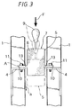
- FIGs. 1 to 3 illustrates a first example.
- a vehicle body of a passenger car as a vehicle has a pair of left and right steel center frames 1 provided on a floor of the vehicle body in such a manner as to erect therefrom, and the respective center frames 1 are connected to each other at upper end portions thereof with a steel cross member 2.
- These center frames 1 and cross member 2 are concealed by an instrument panel 3.
- Both the center frames 1 have a steel bracket 4 on a back thereof, and a shift device 5 is supported between those vehicle side brackets 4.
- This device 5 comprises a device main body 7 and a shift lever 9 protruding from the device main body 7.
- the device main body 7 comprises a manipulating force transmission member connected to the shift lever 9 and accommodated in a synthetic resin box 6, and the shift lever 9 protrudes from a shift gate 8 residing in an upper wall of the box 6.
- a bracket 10 is integrally provided on left and right sides of the box 6, and these device side brackets 10 are placed on two vehicle side brackets 4, respectively, and are fixedly secured to the vehicle side brackets 4 with a plurality of bolts 11.
- a notched groove 13 is formed in a proximal upper surface of the respective device side brackets 10 longitudinally along the full length thereof.
- the device side brackets 10 and those two notched grooves 13 are formed simultaneously with the formation of the box 6.
- Both the device side brackets10 each having the notched groove 13 constitute an impact energy absorption body A, and therefore the device main boy 7 is fixed to the vehicle body via this impact energy absorption body A.
- the impact energy absorption body A and hence both the device side brackets 10 are broken at the notched grooves 13, the device 5 is allowed move in a direction (a) in which the impact energy is applied to a position indicated by two-dot chain lines in Fig. 3.
- the impact energy F is absorbed.
- both the device side brackets 10 may be formed of a steel sheet, while both the vehicle side brackets 4 may be formed of a synthetic resin having the notched groove 13.
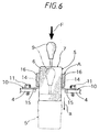
- Figs. 4 to 6 illustrates a second example.
- a bracket 10 is integrally provided on left and right sides of the synthetic resin box 6, and these device side brackets 10 are placed on both the vehicle side brackets 14 and are then fixedly secured to the vehicle body side brackets 4 with a plurality of bolts 11.
- the respective device side brackets 10 are formed of a steel sheet and each comprise an insert portion 14 partially embedded in the box 6 when it is molded and a fixedly securing portion 15 bent at substantially right angles relative to the insert portion 14 and having formed therein a plurality of bolt through holes.
- Front and rear edges of the insert portion 14 each have an inclined portion (b) which is formed as a distance between the front and rear edges gradually increases downwardly from an upper edge of the insert portion 14 and are embedded at both the inclined portions (b) and in the vicinity thereof and both upper end portions contiguous, respectively, with the inclined portions (b) and in the vicinity thereof in a pair of front and rear elongated projections 16 which are integral with the box 6 and extend in parallel with both the inclined portions (b).
- the device side brackets 10 having two sets of left and right insert portion 14 and the pair of front and rear elongated projections 16 constitute an impact energy absorption body A, and therefore the device main body 7 is fixed to the vehicle body via the impact energy absorption body A.
- the insert portion 14 breaks the upper end portions of the front and rear elongated projections 16, expands the elongated projections 16 in fore and aft directions and breaks them entirely, this series of actions by the insert portion 14 being arranged to happen sequentially in that order, and as shown by two-dot chain lines in Fig. 6, the device 5 is allowed to move in the impact energy applied direction.
- the impact energy F is absorbed .
- the insert portion 14 may be provided on the box 6 in a vertically inverted fashion, and both the front and rear elongated projections 16 may be provided on the vehicle side brackets 4, which are formed of a synthetic resin.
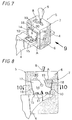
- Figs. 7 to 10 illustrates a third example.
- a bracket 10 is integrally provided on the left and right sides of the synthetic resin box 6, and those device side brackets 10 are placed on the vehicle body side brackets 4, respectively, and fixedly secured to the vehicle body side brackets 4 with a plurality of bolts 11.
- the respective device side brackets 10 are formed from a steel sheet and comprises an insert portion 14 partially embedded in and made integral with the box 6 when it is molded and a fixedly securing portion 15 bent at substantially right angles relative to the insert portion 14 and having formed therein a plurality of bolt through holes.
- the insert portion 14 is constituted by a flat plate portion 17 parallel with both the left and right sides of the box 6 and front and rear hooked portions 18 contiguous with front and rear edges of the flat plate portion 17, respectively.
- the front and rear hooked portions 18 are inclined such that a distance between the front and rear hooked portions 18 gradually decreases downwardly from an upper edge thereof.
- a plate-like protrusion 19 integral with the left and right side walls of the box 6 is molded in a space formed by the flat-plate like portion 17and the front and rear hooked portions 18 so as to be secured to the insert portion 14 tightly and a rivet-like small projection 20 residing on both the projections 19, respectively, is molded by a through hole 21 in the plate-like portion 17 and a mold so as to tightly be secured to the through holes 21.
- the device side brackets 10 having two sets of left and right insert portions 14 and the plate-like projections 19 constitute an impact absorption body A, and therefore the device main body 7 is fixed to the vehicle body via the impact energy absorption body A.
- an impact energy F which is equal to or greater than a predetermined value is applied to the shift lever 9 from above, the impact energy absorption body A is broken.
- both the plate-like portions 19 expands the front and rear hooked portions 18 of in fore and aft directions, as shown by two-dot chain lines in Fig. 9, the device 5 is allowed to move in the direction in which the impact energy applied direction.
- the impact energy F can be absorbed.
- the insert portion 14 may be provided on the box 6 in a vertically inverted fashion, and both the right and both the projections 19 can be provided on the vehicle side brackets 4 if the brackets 4 are molded of a synthetic resin.
- Figs. 11 to 14 illustrates a fourth example.
- the synthetic resin box 6 comprises an upper portion 22 having a wider transverse width, a lower portion 23 having a narrower transverse width and an intermediate portion 24 located between the upper and lower portions 22, 23 and having a transverse width which gradually decreases from an upper side toward a lower side.
- a bracket 10 is integrally provided on left and right inclined sides of the intermediate portion 24, respectively, and these device side brackets 10 are placed on the vehicle body side brackets 4, respectively, whereby the former is fixedly secured to the latter with a plurality of bolts 11.
- the respective device side brackets 10 are formed from a steel sheet and comprises an insert portion 14 partially embedded in the intermediate portion 24 of the box 6 when it is molded and a fixedly securing portion 15 bent at substantially right angles relative to the left and right sides of the upper portion 22 of the insert portion 14 in the vicinity of a boundary between the upper and intermediate portions 22, 24 of the box 6 and having formed therein plurality of bolt through holes 25.
- the front and rear widths of the insert portion 14 is constant and front and rear edge portions and end portions on a lower edge portion thereof are integral with the box 6, and they are embedded in a pair of front and rear elongated projections 16.
- the device side brackets 10 each having a set of left and right bent portions (d) constitute an impact energy absorption body A, and therefore the device main body 7 is fixedly secured to the vehicle body via the impact energy absorption body A.
- the impact energy absorption body A is broken.
- the device side brackets 10 are further bent from the bent portions, and as shown by two-dot chain lines in Fig. 12, the device 5 is allowed to move in the impact energy applied direction.
- the impact energy F is absorbed.
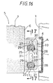
- Figs. 15 to 18 illustrates a fifth example.
- a bracket 10 is integrally provided on left and right sides of the synthetic resin box 6, and those device side brackets 10 are overlapped on rear sides of the vehicle body side brackets 14 and are then fixedly secured to the vehicle body side brackets 4, respectively, with a plurality of bolts 11, in the illustrated example, 2 bolts 11, and nuts 26 screwed thereon, respectively.
- the respective device side brackets 10 each have square bolt through holes at upper and lower portions thereof and thin portions 27 extending upwardly from upper edges of the respective bolt through holes 25.
- a steel collar 28 through which the bolt 11 is put is inserted into the respective bolt through holes 25.
- the respective collar s 28 are molded into a shape having a pentagonal cross-section through a forging process so as to approach the lower side and left and right sides of the bolt through hole 25.
- the collar 28 has an angled surface 29 facing an upper surface of the bolt through hole 25.
- a ridgeline 30 of the angled surface 29 is located close to the thin portion 27, which is a weak portion 30.
- An end face of the respective collars 28 abuts with the vehicle side bracket 4, and the other end face thereof abuts with a washer fitted over the bolt 11.
- the device side brackets 10 having two sets of left and right thin portions 27, bolts 11, nuts 26 and collars 28 constitute an impact energy absorption body A, and therefore the device main body 7 is fixedly secured to the vehicle body via the impact energy absorption body A.
- the impact energy absorption body A is broken.
- the thin portions 27 of the respective device side brackets 10 are broken by the respective collars 28 each having an angled surface 29, the device 5 is allowed to move in the impact energy applied direction (a).
- the impact energy F is absorbed.
- the device side brackets 10 may be formed of a steel sheet, and the vehicle body side brackets 4 may be formed from a synthetic resin, whereby the thin portions of the vehicle side brackets 4 may be broken by the collars 28.
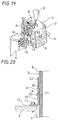
- Figs. 19 and 20 illustrates a sixth example.
- the respective device side brackets 10 are formed of a steel sheet and comprises an insert portion 14 made integral with the box 6 when it is molded and a fixedly securing portion 15 bent substantially at right angles relative to the insert portion 14 and having formed therein a plurality of bolt through holes.
- a rivet-like small projection 20 residing on the left and right sides of the box 6 is formed by a through hole 21 in the respective insert portions 14 and a mold in such a manner as to tightly be secured to the through hole 21.
- the respective insert portions 14 each have an arc-like outer circumferential surface 32, and a plurality of projections 33 residing on the left and right sides of the box 6 and arranged substantially radially thereon are tightly secured to the arc-like outer circumferential surface 32 at inner end portions thereof.
- the device side brackets 10 having two sets of left and right insert portions 14, through holes 21, small projections 20, the plurality of projections 33 constitute an impact energy absorption body A, and therefore the device main body 7 is fixedly secured to the vehicle body via the impact energy absorption body A.
- the impact energy absorption body A is broken.
- the small projections 20 are broken, and some of the projections 33 are chipped off by the insert portion 14, and this allows the device 5 to move in the impact energy applied direction (a).
- the impact energy F is absorbed.
- the box 6 may be provided with the insert portion 14 vertically inverted, and the respective projections 33 may be provided on the vehicle side brackets 4 by forming the brackets from a synthetic resin.
- a vehicle body of a passenger car as a vehicle has a pair of left and right steel center frames 51 provided on a floor of the vehicle body in such a manner as to erect therefrom, and the respective center frames 51 are connected to each other at upper end portions thereof with a steel cross member 52.
- These center frames 51 and cross member 52 are concealed by an instrument panel 53.
- Both the center frames 51 have a steel bracket 54 on a back thereof, and a shift device 55 is supported between those vehicle side brackets 54.
- This device 55 comprises a device main body 56 and a shift lever 57 protruding from the device main body 56.
- the device main body 56 comprises a manipulating force transmission member 58 connected to the shift lever 57 and a synthetic resin box 59 accommodating therein the member 58, and a cover member 60 is placed on an upper portion of the box 59 so as to cover the same and is attached to the box 59 with a plurality of machine screws 61.
- the shift lever 57 has a steel rod-like lever main body 62 and a synthetic resin manipulating knob 63.
- a shift gate 64 is provided in an upper wall of the box 59, and a gate matching the gate 64 is also provided in the cover member 60, but the illustration thereof is omitted herein.
- the rod-like lever main body 62 extends through those shift gates.
- a bracket 65 is integrally provided on left and right sides of the box, respectively, and these device side brackets 65 are placed over the vehicle body side brackets 54 and are then fixedly secured thereto with a plurality of bolts 66. This positions the shift gate 64 of the box 59 in an opening 67 in the instrument panel 53, and the shift lever 57 protrudes into the passenger compartment through the opening 67.
- the manipulating force transmission member 58 has a link member 69 comprising a hollow cylindrical portion 68 having an axis extending transversely, and the link member 69 is supported on the box 59 via a first support shaft 70 inserted into the hollow cylindrical portion 68 in such a manner as to freely rock in fore and aft directions.
- a pair of front and rear bearing members 71 are provided on an upper surface of the link member 69, a support member 72 provided at a lower edge of the rod-like lever main body 62 is supported on those bearing members 71 via a second support shaft 73 in such a manner as to freely rock in transverse directions.
- a steering wheel 74 is disposed above the shift lever 57. Therefore, an impact energy F generated by the head of the driver in conjunction with a frontal collision between passenger vehicles is applied to the manipulating knob 63 of the shift lever 67 from above and diagonally the rear.
- the rod-like lever main body 62 of the shift lever 57 is disposed on the device main body 56 such that its axis (a) intersects with an impact energy applied direction (b), so that a component of force (f) is generated based on the impact energy so applied in a bending direction.
- the shift lever 77 resides in the D-range as shown in Fig. 24, and at this time the axis (a) of the rod-like lever main body 62 is inclined rearward at an angle of 55 degrees relative to a vertical line (c), and the impact energy applied direction (b) is inclined at an angle of 30 degrees relative to the vertical line (c). Consequently, the intersecting angle ⁇ between the axis (a) and the impact energy applied direction (b) is about 25 degrees.
- An impact energy absorption operation as described above also occurs while the shift lever 57 is located in an N-range and an L-range.
- the rod-like lever main body 62 may be inclined forward at a predetermined angle relative to the vertical line (c). Furthermore, in order for the rod-like lever main body 62 to easily be bent by virtue of the impact energy F, as a means for attaining this end, the rod-like lever main body 62 is made thinner at a portion confronting the edge portion of the shift gate 64 than other portions thereof and a notch is formed in the portion confronting the edge portion. Moreover, the rod-like lever main body 62 may be formed of an impact energy absorbing material.
- an impact energy absorption structure for a shifting device for a vehicular transmission can be provided which provides a high impact energy absorption performance.
Abstract
Description
- The present invention relates to an impact energy absorption structure for a shifting device of vehicular transmission, and more particularly to an impact energy absorption structure for a shifting device of a vehicular transmission which comprises a main body and a shift lever protruding from the main body.
- Conventionally known as an impact energy absorption structure of this type is an impact energy absorption structure constructed such that a main body is swingably provided on a vehicle body frame in such a manner as to be constrained with a constraining member against rocking thereof, whereby when an impact energy is applied to a shifting device of the vehicular transmission, the constraint with the constraining member is released so that the device main body is allowed to rock (Japanese Unexamined Patent Publication No. Hei. 10-16597).
- However, if the impact absorption structure is constructed using a rock constraining system as seen in the prior art, there is caused a problem in which the construction of such a structure gets complicated to thereby increase its production costs. This is a first problem of the prior art.
- In addition to this, conventionally known as an impact energy absorption structure of this type is an impact energy absorption structure in which a manipulating knob of a shift lever is formed of an elastic material and in which a part of a rod-like lever main body of the shift lever which resides in the manipulating knob is bent to the left of the driver, a notch being formed in the bent portion (Japanese Unexamined Patent Publication No. Hei. 5-246262).
- In the conventional impact energy absorption structure, however, since a distal end portion of the shift lever is constructed so as to be bent by virtue of an impact energy from the driver, there is a drawback in which an impact energy absorption stroke is short, a low impact energy absorption performance being thereby provided. This is a second problem of the prior art.
- An object of the present invention is to provide an impact energy absorption structure that is simple in construction and low in cost.
- The object above can be achieved by an impact energy absorption structure for a shifting device of a vehicular transmission, the structure, according to the present invention, comprising:
- a main body;
- a shift lever protruding from the main body;
- an impact absorption member, through which the main body is fixed to a vehicle body, adapted to be broken by an impact force more than a predetermined force applied to the shifting device, to thereby allow the shifting device to move in an impact force applied direction.
-
- In addition, the object above can also be achieved by an impact energy absorption structure for a shifting device of a vehicular transmission which comprises a main body and a shift lever protruding from the main body, wherein the main body is fixed to a vehicle body via an impact absorption body adapted to be broken by an impact energy applied to the shifting device, whereby the shifting device is allowed to move in an impact energy applied direction.
- Thus, if the main body is constructed using a fixing system as described above, it is possible to make the construction simpler and the cost lower than as with the rock conventional constraining system.
- Further, it is also an object of the present invention to provide an impact energy absorption structure having a high impact energy absorption performance.
- The object above can be achieved by an impact energy absorption structure for a shifting device of a vehicular transmission, the structure, according to the present invention, comprising:
- a main body;
- a shift lever protruding from the main body;
- an impact absorption member, through which the main body
is fixed to a vehicle body, adapted to be broken by an impact
force more than a predetermined force applied to the shifting
device, to thereby allow the shifting device to move in an impact
force applied direction,
wherein the main body comprises a shift gate from which the shift lever protrudes, and the shift lever is provided with a rod-like lever main body which is disposed on the main body in such a manner that an axis of said rod-like lever main body intersects with the impact force applied direction. -
- Furthermore, the object above can also be achieved by an impact energy absorption structure for a shifting device of vehicular transmission, according to the present invention, comprising a main body and a shift lever protruding from a shifting gate of the main body, wherein a rod-like lever main body of the shift lever is disposed on the main body such that an axis of the rod-like lever main body intersects with an impact energy applied direction in order that the rod-like lever main body is bent by an edge portion of the shift gate by virtue of an impact energy applied to the shift lever.
- In the aforesaid construction, when an impact energy equal to or larger than a predetermined value is applied, for instance, by the head of the driver to a distal end portion, i.e., the manipulating knob of the rod-like lever main body of the shift lever, the rod-like lever main body is bent at an edge portion of the shift gate as a fulcrum, whereby the impact energy is absorbed. In this case, since the rod-like lever main body is bent at an intermediate portion thereof, there is provided a relatively long impact energy absorption stroke.
-
- Fig. 1 shows a side view of a first example;
- Fig. 2 shows a perspective view of the first example;
- Fig. 3 shows an illustration as viewed in a direction
indicated by an
arrow 3 in Fig. 2; - Fig. 4 shows a perspective view of a second example;
- Fig. 5 shows a side view of the second example;
- Fig. 6 shows an illustration as viewed in a direction
indicated by an
arrow 6 in Fig. 4; - Fig. 7 shows a perspective view of a third example;
- Fig. 8 shows a side view of a third example;
- Fig. 9 shows an illustration as viewed in a direction
indicated by an
arrow 9; - Fig. 10 shows a sectional view taken along the line 10-10 of Fig. 8;
- Fig. 11 shows a perspective view of a fourth example;
- Fig. 12 shows an illustration as viewed in a direction
indicated by an
arrow 12 in Fig. 11; - Fig. 13 shows an illustration as viewed in a direction
indicated by an
arrow 13 in Fig. 12; - Fig. 14 shows a sectional view taken along the line 14-14 of Fig. 13;
- Fig. 15 shows a perspective view of a fix example;
- Fig. 16 shows a partially cut-away rear view of the fifth example;
- Fig. 17 shows a sectional view taken along the line 17-17 of Fig. 16;
- Fig. 18 shows an illustraion showing an operation of the fifth example, which corresponds to Fig. 17;
- Fig. 19 shows a perspective view of a sixth example;
- Fig. 20 shows a sectional view taken along the line 20-20 of Fig. 19;
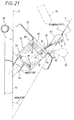
- Fig. 21 shows a side view of a shifting device provided with an impact energy absorption structure;
- Fig. 22 shows a perspective view of the shifting device provided with the impact energy absorption structure;
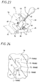
- Fig. 23 shows a perspective view of an internal structure of the shift device; and
- Fig. 24 shows a partially enlarged perspective view showing an upper surface of a box.
-
- In a description of a mode of operation of the present invention, "front," "rear," "left," and "right" indicate directions based on an understanding that the "front" represents a direction in which a vehicle advances.
- Figs. 1 to 3 illustrates a first example. A vehicle body of a passenger car as a vehicle has a pair of left and right
steel center frames 1 provided on a floor of the vehicle body in such a manner as to erect therefrom, and therespective center frames 1 are connected to each other at upper end portions thereof with asteel cross member 2. Thesecenter frames 1 andcross member 2 are concealed by aninstrument panel 3. - Both the
center frames 1 have asteel bracket 4 on a back thereof, and ashift device 5 is supported between thosevehicle side brackets 4. Thisdevice 5 comprises a devicemain body 7 and ashift lever 9 protruding from the devicemain body 7. The devicemain body 7 comprises a manipulating force transmission member connected to theshift lever 9 and accommodated in asynthetic resin box 6, and theshift lever 9 protrudes from ashift gate 8 residing in an upper wall of thebox 6. Abracket 10 is integrally provided on left and right sides of thebox 6, and thesedevice side brackets 10 are placed on twovehicle side brackets 4, respectively, and are fixedly secured to thevehicle side brackets 4 with a plurality ofbolts 11. This positions theshift gate 8 of the box within an opening 12 in theinstrument panel 3, and theshift lever 9 protrudes into the passenger compartment from the opening 12. Anotched groove 13 is formed in a proximal upper surface of the respectivedevice side brackets 10 longitudinally along the full length thereof. Thedevice side brackets 10 and those twonotched grooves 13 are formed simultaneously with the formation of thebox 6. - Both the device side brackets10 each having the notched
groove 13 constitute an impact energy absorption body A, and therefore the devicemain boy 7 is fixed to the vehicle body via this impact energy absorption body A. In this state, when an impact energy F equal to or greater than a predetermined value is applied to theshift lever 9 from above, the impact energy absorption body A and hence both thedevice side brackets 10 are broken at the notchedgrooves 13, thedevice 5 is allowed move in a direction (a) in which the impact energy is applied to a position indicated by two-dot chain lines in Fig. 3. Thus, the impact energy F is absorbed. - In the first example, both the
device side brackets 10 may be formed of a steel sheet, while both thevehicle side brackets 4 may be formed of a synthetic resin having the notchedgroove 13. - Figs. 4 to 6 illustrates a second example. In this case, a
bracket 10 is integrally provided on left and right sides of thesynthetic resin box 6, and thesedevice side brackets 10 are placed on both thevehicle side brackets 14 and are then fixedly secured to the vehiclebody side brackets 4 with a plurality ofbolts 11. - The respective
device side brackets 10 are formed of a steel sheet and each comprise aninsert portion 14 partially embedded in thebox 6 when it is molded and a fixedly securingportion 15 bent at substantially right angles relative to theinsert portion 14 and having formed therein a plurality of bolt through holes. Front and rear edges of theinsert portion 14 each have an inclined portion (b) which is formed as a distance between the front and rear edges gradually increases downwardly from an upper edge of theinsert portion 14 and are embedded at both the inclined portions (b) and in the vicinity thereof and both upper end portions contiguous, respectively, with the inclined portions (b) and in the vicinity thereof in a pair of front and rearelongated projections 16 which are integral with thebox 6 and extend in parallel with both the inclined portions (b). - The
device side brackets 10 having two sets of left andright insert portion 14 and the pair of front and rearelongated projections 16 constitute an impact energy absorption body A, and therefore the devicemain body 7 is fixed to the vehicle body via the impact energy absorption body A. In this state, when an impact energy F which is larger than a predetermined value is applied to theshift lever 9 from above, the impact energy so applied breaks the impact energy absorption body A. In other words, theinsert portion 14 breaks the upper end portions of the front and rearelongated projections 16, expands theelongated projections 16 in fore and aft directions and breaks them entirely, this series of actions by theinsert portion 14 being arranged to happen sequentially in that order, and as shown by two-dot chain lines in Fig. 6, thedevice 5 is allowed to move in the impact energy applied direction. Thus, the impact energy F is absorbed . - In the second example, the
insert portion 14 may be provided on thebox 6 in a vertically inverted fashion, and both the front and rearelongated projections 16 may be provided on thevehicle side brackets 4, which are formed of a synthetic resin. - Figs. 7 to 10 illustrates a third example. In this case, a
bracket 10 is integrally provided on the left and right sides of thesynthetic resin box 6, and thosedevice side brackets 10 are placed on the vehiclebody side brackets 4, respectively, and fixedly secured to the vehiclebody side brackets 4 with a plurality ofbolts 11. - The respective
device side brackets 10 are formed from a steel sheet and comprises aninsert portion 14 partially embedded in and made integral with thebox 6 when it is molded and a fixedly securingportion 15 bent at substantially right angles relative to theinsert portion 14 and having formed therein a plurality of bolt through holes. Theinsert portion 14 is constituted by aflat plate portion 17 parallel with both the left and right sides of thebox 6 and front and rearhooked portions 18 contiguous with front and rear edges of theflat plate portion 17, respectively. The front and rearhooked portions 18 are inclined such that a distance between the front and rearhooked portions 18 gradually decreases downwardly from an upper edge thereof. A plate-like protrusion 19 integral with the left and right side walls of thebox 6 is molded in a space formed by the flat-plate like portion 17and the front and rearhooked portions 18 so as to be secured to theinsert portion 14 tightly and a rivet-likesmall projection 20 residing on both theprojections 19, respectively, is molded by a throughhole 21 in the plate-like portion 17 and a mold so as to tightly be secured to the through holes 21. - The
device side brackets 10 having two sets of left andright insert portions 14 and the plate-like projections 19 constitute an impact absorption body A, and therefore the devicemain body 7 is fixed to the vehicle body via the impact energy absorption body A. In this state, if an impact energy F which is equal to or greater than a predetermined value is applied to theshift lever 9 from above, the impact energy absorption body A is broken. In other words, since both the plate-like portions 19 expands the front and rearhooked portions 18 of in fore and aft directions, as shown by two-dot chain lines in Fig. 9, thedevice 5 is allowed to move in the direction in which the impact energy applied direction. Thus, the impact energy F can be absorbed. - In the third example, the
insert portion 14 may be provided on thebox 6 in a vertically inverted fashion, and both the right and both theprojections 19 can be provided on thevehicle side brackets 4 if thebrackets 4 are molded of a synthetic resin. - Figs. 11 to 14 illustrates a fourth example. In this case, the
synthetic resin box 6 comprises anupper portion 22 having a wider transverse width, alower portion 23 having a narrower transverse width and anintermediate portion 24 located between the upper andlower portions bracket 10 is integrally provided on left and right inclined sides of theintermediate portion 24, respectively, and thesedevice side brackets 10 are placed on the vehiclebody side brackets 4, respectively, whereby the former is fixedly secured to the latter with a plurality ofbolts 11. - The respective
device side brackets 10 are formed from a steel sheet and comprises aninsert portion 14 partially embedded in theintermediate portion 24 of thebox 6 when it is molded and a fixedly securingportion 15 bent at substantially right angles relative to the left and right sides of theupper portion 22 of theinsert portion 14 in the vicinity of a boundary between the upper andintermediate portions box 6 and having formed therein plurality of bolt through holes 25. The front and rear widths of theinsert portion 14 is constant and front and rear edge portions and end portions on a lower edge portion thereof are integral with thebox 6, and they are embedded in a pair of front and rearelongated projections 16. - The
device side brackets 10 each having a set of left and right bent portions (d) constitute an impact energy absorption body A, and therefore the devicemain body 7 is fixedly secured to the vehicle body via the impact energy absorption body A. In this state, if an impact energy F equal to or larger than a predetermined value is applied to theshift lever 9 from above, the impact energy absorption body A is broken. In other words, thedevice side brackets 10 are further bent from the bent portions, and as shown by two-dot chain lines in Fig. 12, thedevice 5 is allowed to move in the impact energy applied direction. Thus, the impact energy F is absorbed. - Figs. 15 to 18 illustrates a fifth example. In this case, a
bracket 10 is integrally provided on left and right sides of thesynthetic resin box 6, and thosedevice side brackets 10 are overlapped on rear sides of the vehiclebody side brackets 14 and are then fixedly secured to the vehiclebody side brackets 4, respectively, with a plurality ofbolts 11, in the illustrated example, 2bolts 11, andnuts 26 screwed thereon, respectively. - The respective
device side brackets 10 each have square bolt through holes at upper and lower portions thereof andthin portions 27 extending upwardly from upper edges of the respective bolt through holes 25. Asteel collar 28 through which thebolt 11 is put is inserted into the respective bolt through holes 25. The respective collar s 28 are molded into a shape having a pentagonal cross-section through a forging process so as to approach the lower side and left and right sides of the bolt throughhole 25. Thecollar 28 has an angledsurface 29 facing an upper surface of the bolt throughhole 25. Aridgeline 30 of theangled surface 29 is located close to thethin portion 27, which is aweak portion 30. An end face of therespective collars 28 abuts with thevehicle side bracket 4, and the other end face thereof abuts with a washer fitted over thebolt 11. - The
device side brackets 10 having two sets of left and rightthin portions 27,bolts 11,nuts 26 andcollars 28 constitute an impact energy absorption body A, and therefore the devicemain body 7 is fixedly secured to the vehicle body via the impact energy absorption body A. In this state, when an impact energy F equal to or larger than a predetermined value is applied to theshift lever 9 from above, the impact energy absorption body A is broken. In other words, as shown in Fig. 18, since thethin portions 27 of the respectivedevice side brackets 10 are broken by therespective collars 28 each having anangled surface 29, thedevice 5 is allowed to move in the impact energy applied direction (a). Thus, the impact energy F is absorbed. - In the fifth example, the
device side brackets 10 may be formed of a steel sheet, and the vehiclebody side brackets 4 may be formed from a synthetic resin, whereby the thin portions of thevehicle side brackets 4 may be broken by thecollars 28. - Figs. 19 and 20 illustrates a sixth example. In this case, the respective
device side brackets 10 are formed of a steel sheet and comprises aninsert portion 14 made integral with thebox 6 when it is molded and a fixedly securingportion 15 bent substantially at right angles relative to theinsert portion 14 and having formed therein a plurality of bolt through holes. A rivet-likesmall projection 20 residing on the left and right sides of thebox 6 is formed by a throughhole 21 in therespective insert portions 14 and a mold in such a manner as to tightly be secured to the throughhole 21. Therespective insert portions 14 each have an arc-like outercircumferential surface 32, and a plurality ofprojections 33 residing on the left and right sides of thebox 6 and arranged substantially radially thereon are tightly secured to the arc-like outercircumferential surface 32 at inner end portions thereof. - The
device side brackets 10 having two sets of left andright insert portions 14, throughholes 21,small projections 20, the plurality ofprojections 33 constitute an impact energy absorption body A, and therefore the devicemain body 7 is fixedly secured to the vehicle body via the impact energy absorption body A. In this state, when an impact energy F equal to or larger than a predetermined value is applied to theshift lever 9 from above, the impact energy absorption body A is broken. In other words, thesmall projections 20 are broken, and some of theprojections 33 are chipped off by theinsert portion 14, and this allows thedevice 5 to move in the impact energy applied direction (a). Thus, the impact energy F is absorbed. - According to the aforesaid construction, all the impact energy directed toward the arc-like outer
circumferential surface 32 of theinsert portion 14 can be absorbed. In this sixth example, thebox 6 may be provided with theinsert portion 14 vertically inverted, and therespective projections 33 may be provided on thevehicle side brackets 4 by forming the brackets from a synthetic resin. - Hereinafter, preferred embodiments according to the second aspect of the preesent invention will be explained.
- In Figs. 21 and 22, a vehicle body of a passenger car as a vehicle has a pair of left and right steel center frames 51 provided on a floor of the vehicle body in such a manner as to erect therefrom, and the respective center frames 51 are connected to each other at upper end portions thereof with a
steel cross member 52. These center frames 51 andcross member 52 are concealed by aninstrument panel 53. - Both the center frames 51 have a
steel bracket 54 on a back thereof, and ashift device 55 is supported between thosevehicle side brackets 54. Thisdevice 55 comprises a devicemain body 56 and ashift lever 57 protruding from the devicemain body 56. As shown in Fig. 23, the devicemain body 56 comprises a manipulatingforce transmission member 58 connected to theshift lever 57 and asynthetic resin box 59 accommodating therein themember 58, and acover member 60 is placed on an upper portion of thebox 59 so as to cover the same and is attached to thebox 59 with a plurality ofmachine screws 61. - The
shift lever 57 has a steel rod-like levermain body 62 and a syntheticresin manipulating knob 63. As is clearly shown in Fig. 24, ashift gate 64 is provided in an upper wall of thebox 59, and a gate matching thegate 64 is also provided in thecover member 60, but the illustration thereof is omitted herein. The rod-like levermain body 62 extends through those shift gates. Abracket 65 is integrally provided on left and right sides of the box, respectively, and thesedevice side brackets 65 are placed over the vehiclebody side brackets 54 and are then fixedly secured thereto with a plurality ofbolts 66. This positions theshift gate 64 of thebox 59 in anopening 67 in theinstrument panel 53, and theshift lever 57 protrudes into the passenger compartment through theopening 67. - The manipulating
force transmission member 58 has alink member 69 comprising a hollowcylindrical portion 68 having an axis extending transversely, and thelink member 69 is supported on thebox 59 via afirst support shaft 70 inserted into the hollowcylindrical portion 68 in such a manner as to freely rock in fore and aft directions. A pair of front andrear bearing members 71 are provided on an upper surface of thelink member 69, asupport member 72 provided at a lower edge of the rod-like levermain body 62 is supported on those bearingmembers 71 via asecond support shaft 73 in such a manner as to freely rock in transverse directions. - In Fig. 21, a
steering wheel 74 is disposed above theshift lever 57. Therefore, an impact energy F generated by the head of the driver in conjunction with a frontal collision between passenger vehicles is applied to the manipulatingknob 63 of theshift lever 67 from above and diagonally the rear. - In this case, the rod-like lever
main body 62 of theshift lever 57 is disposed on the devicemain body 56 such that its axis (a) intersects with an impact energy applied direction (b), so that a component of force (f) is generated based on the impact energy so applied in a bending direction. In a state illustrated in Figs. 21 and 22, the shift lever 77 resides in the D-range as shown in Fig. 24, and at this time the axis (a) of the rod-like levermain body 62 is inclined rearward at an angle of 55 degrees relative to a vertical line (c), and the impact energy applied direction (b) is inclined at an angle of 30 degrees relative to the vertical line (c). Consequently, the intersecting angle Θ between the axis (a) and the impact energy applied direction (b) is about 25 degrees. - When an impact energy equal to or larger than a predetermined value is applied to the manipulating
knob 63 of theshift lever 57 by the head of the driver in the aforesaid state, a component of force (f) based on the impact energy so applied is generated in the bending direction, and as shown by alternate long and short dash lines in Figs. 21 and 22, the component of force (f) so generated bends the rod-like levermain body 62 at anedge portion 75 of the D-range in theshift gate 64 as a fulcrum in a clockwise direction. In this case, since the rod-like levermain body 62 is bend at an intermediate portion thereof, the impact energy absorption stroke becomes relatively long, providing a high impact energy absorption performance. - An impact energy absorption operation as described above also occurs while the
shift lever 57 is located in an N-range and an L-range. - In addition, the rod-like lever
main body 62 may be inclined forward at a predetermined angle relative to the vertical line (c). Furthermore, in order for the rod-like levermain body 62 to easily be bent by virtue of the impact energy F, as a means for attaining this end, the rod-like levermain body 62 is made thinner at a portion confronting the edge portion of theshift gate 64 than other portions thereof and a notch is formed in the portion confronting the edge portion. Moreover, the rod-like levermain body 62 may be formed of an impact energy absorbing material. - Note that the examples are separately explained in the above-mentioned description, whereas it is possible to use a plurality of embodiments one another.
- According to a first aspect of the present inventions, with the constructions described above, it is possible to provide an impact energy absorption structure for a shift device for a vehicular transmission.
- In addition, according to a second aspect of the present invention, with the construction having been described heretofore, an impact energy absorption structure for a shifting device for a vehicular transmission can be provided which provides a high impact energy absorption performance.
- While there has been described in connection with the preferred embodiment of the invention, it will be obvious to those skilled in the art that various changes and modifications may be made therein without departing from the invention, and it is aimed, therefore, to cover in the appended claim all such changes and modifications as fall within the true spirit and scope of the invention.
Claims (5)
- An impact energy absorption structure for a shifting device of a vehicular transmission, said structure comprising:a main body;a shift lever protruding from said main body;an impact absorption member, through which said main body is fixed to a vehicle body, adapted to be broken by an impact force more than a predetermined force applied to said shifting device, to thereby allow said shifting device to move in an impact force applied direction.
- The impact energy absorption structure according to claim 1, wherein said impact absorption member comprises a side bracket integrally formed with said main body and fixed to said vehicle body, and said side bracket has a notched groove for shearing said side bracket when said impact force is applied to said shifting device.
- The impact energy absorption structure according to claim 1, wherein said impact absorption member comprises:a side bracket fixedly secured to said vehicle body;a projecting portion mounted on said main body and engaged with said side bracket,
wherein the engagement between said side bracket and said projecting portion is releasable when said impact force is applied to said shifting device. - The impact energy absorption structure according to claim 1, wherein said main body comprises a shift gate from which said shift lever protrudes, and said shift lever is provided with a rod-like lever main body which is disposed on said main body in such a manner that an axis of said rod-like lever main body intersects with said impact force applied direction.
- The impact energy absorption structure according to claim 4, wherein said rod-like lever main body (12) is bendable by an edge portion of said shift gate when said shift lever is subject to the impact force.
Priority Applications (1)
| Application Number | Priority Date | Filing Date | Title |
|---|---|---|---|
| EP05017852A EP1604871B1 (en) | 1998-11-20 | 1999-11-19 | Impact energy absorption structure for a shifting device of vehicle transmission |
Applications Claiming Priority (4)
| Application Number | Priority Date | Filing Date | Title |
|---|---|---|---|
| JP33117598 | 1998-11-20 | ||
| JP33117598A JP3712875B2 (en) | 1998-11-20 | 1998-11-20 | Impact force absorbing structure of vehicle speed change operation device |
| JP33672698A JP3569635B2 (en) | 1998-11-27 | 1998-11-27 | Impact force absorbing structure of vehicle speed change operation device |
| JP33672698 | 1998-11-27 |
Related Child Applications (1)
| Application Number | Title | Priority Date | Filing Date |
|---|---|---|---|
| EP05017852A Division EP1604871B1 (en) | 1998-11-20 | 1999-11-19 | Impact energy absorption structure for a shifting device of vehicle transmission |
Publications (3)
| Publication Number | Publication Date |
|---|---|
| EP1002702A2 true EP1002702A2 (en) | 2000-05-24 |
| EP1002702A3 EP1002702A3 (en) | 2003-09-17 |
| EP1002702B1 EP1002702B1 (en) | 2006-06-07 |
Family
ID=26573770
Family Applications (2)
| Application Number | Title | Priority Date | Filing Date |
|---|---|---|---|
| EP05017852A Expired - Lifetime EP1604871B1 (en) | 1998-11-20 | 1999-11-19 | Impact energy absorption structure for a shifting device of vehicle transmission |
| EP99123126A Expired - Lifetime EP1002702B1 (en) | 1998-11-20 | 1999-11-19 | Impact energy absorption structure for a shifting device of vehicular transmission |
Family Applications Before (1)
| Application Number | Title | Priority Date | Filing Date |
|---|---|---|---|
| EP05017852A Expired - Lifetime EP1604871B1 (en) | 1998-11-20 | 1999-11-19 | Impact energy absorption structure for a shifting device of vehicle transmission |
Country Status (3)
| Country | Link |
|---|---|
| US (1) | US6273466B1 (en) |
| EP (2) | EP1604871B1 (en) |
| DE (2) | DE69938206T2 (en) |
Cited By (1)
| Publication number | Priority date | Publication date | Assignee | Title |
|---|---|---|---|---|
| FR2979999A1 (en) * | 2011-09-12 | 2013-03-15 | Peugeot Citroen Automobiles Sa | System for fixing head-up vision case on crosspiece of fascia of car in vicinity of front windscreen, has disengagement units for automatically disengaging case from crosspiece during frontal shock by releasing bolts from through openings |
Families Citing this family (8)
| Publication number | Priority date | Publication date | Assignee | Title |
|---|---|---|---|---|
| KR20040031254A (en) * | 2002-10-04 | 2004-04-13 | 현대자동차주식회사 | facia mounting type mounting bracket for a shift lever |
| US7077432B2 (en) * | 2003-09-30 | 2006-07-18 | Delphi Technologies, Inc. | Steering column assembly having break-away device |
| JP4971912B2 (en) * | 2007-08-31 | 2012-07-11 | 富士機工株式会社 | Shift lever device |
| US7997548B2 (en) * | 2007-12-31 | 2011-08-16 | Honda Motor Co., Ltd. | Vehicle shifter mounting bracket system and method |
| KR101637723B1 (en) * | 2014-11-11 | 2016-07-08 | 현대자동차주식회사 | Transmission device for automobile |
| USD789265S1 (en) * | 2016-04-28 | 2017-06-13 | Pilot, Inc. | Shift knob cover |
| JP6738270B2 (en) * | 2016-12-26 | 2020-08-12 | 株式会社東海理化電機製作所 | Shift device |
| US11247727B2 (en) | 2019-12-02 | 2022-02-15 | Woven Planet North America, Inc. | Safety-enhanced storage system for autonomous vehicle compute units |
Citations (2)
| Publication number | Priority date | Publication date | Assignee | Title |
|---|---|---|---|---|
| JPH05246262A (en) | 1992-03-04 | 1993-09-24 | Mazda Motor Corp | Operating device for vehicular automatic transmission |
| JPH1016597A (en) | 1996-07-04 | 1998-01-20 | Mitsubishi Motors Corp | Speed change operation device for vehicle |
Family Cites Families (11)
| Publication number | Priority date | Publication date | Assignee | Title |
|---|---|---|---|---|
| US3750492A (en) * | 1971-09-20 | 1973-08-07 | Holmes H Sr | Energy absorbing shift lever |
| US4055230A (en) * | 1974-01-11 | 1977-10-25 | International Harvester Company | Vehicle control armrest in a vibration isolated control module |
| DE2557859C2 (en) * | 1975-01-31 | 1983-01-05 | Nissan Motor Co., Ltd., Yokohama, Kanagawa | Mounting of switches for instruments on the dashboard of a motor vehicle |
| DE2530802A1 (en) * | 1975-07-10 | 1977-01-27 | Volkswagenwerk Ag | SHIFTER STORAGE |
| DE3541825A1 (en) * | 1985-11-27 | 1987-06-04 | Man Nutzfahrzeuge Gmbh | STEERING COLUMN AND SHIFT LEVER SEAL |
| US4873884A (en) * | 1987-09-08 | 1989-10-17 | Toyota Jidosha Kabushi Kaisha | Apparatus for supporting shift lever for transmission |
| FR2673893B1 (en) * | 1991-03-12 | 1995-09-08 | Peugeot | DEVICE FOR FIXING A GEARBOX CONTROL LEVER NEAR A VEHICLE DASHBOARD. |
| DE4404569A1 (en) * | 1993-02-25 | 1994-09-01 | Volkswagen Ag | Deformation element working according to the inversion principle |
| JPH0958288A (en) * | 1995-08-23 | 1997-03-04 | Mitsubishi Motors Corp | Gear shifter |
| JP3693768B2 (en) * | 1996-10-11 | 2005-09-07 | 株式会社東海理化電機製作所 | Shift lever device |
| JP3465555B2 (en) * | 1997-10-08 | 2003-11-10 | 三菱自動車工業株式会社 | Energy absorbing member |
-
1999
- 1999-11-19 EP EP05017852A patent/EP1604871B1/en not_active Expired - Lifetime
- 1999-11-19 EP EP99123126A patent/EP1002702B1/en not_active Expired - Lifetime
- 1999-11-19 US US09/444,580 patent/US6273466B1/en not_active Expired - Fee Related
- 1999-11-19 DE DE69938206T patent/DE69938206T2/en not_active Expired - Lifetime
- 1999-11-19 DE DE69931730T patent/DE69931730T2/en not_active Expired - Fee Related
Patent Citations (2)
| Publication number | Priority date | Publication date | Assignee | Title |
|---|---|---|---|---|
| JPH05246262A (en) | 1992-03-04 | 1993-09-24 | Mazda Motor Corp | Operating device for vehicular automatic transmission |
| JPH1016597A (en) | 1996-07-04 | 1998-01-20 | Mitsubishi Motors Corp | Speed change operation device for vehicle |
Cited By (1)
| Publication number | Priority date | Publication date | Assignee | Title |
|---|---|---|---|---|
| FR2979999A1 (en) * | 2011-09-12 | 2013-03-15 | Peugeot Citroen Automobiles Sa | System for fixing head-up vision case on crosspiece of fascia of car in vicinity of front windscreen, has disengagement units for automatically disengaging case from crosspiece during frontal shock by releasing bolts from through openings |
Also Published As
| Publication number | Publication date |
|---|---|
| EP1604871A1 (en) | 2005-12-14 |
| DE69931730T2 (en) | 2007-05-16 |
| DE69938206D1 (en) | 2008-04-03 |
| EP1002702A3 (en) | 2003-09-17 |
| EP1002702B1 (en) | 2006-06-07 |
| DE69938206T2 (en) | 2009-02-12 |
| EP1604871B1 (en) | 2008-02-20 |
| US6273466B1 (en) | 2001-08-14 |
| DE69931730D1 (en) | 2006-07-20 |
Similar Documents
| Publication | Publication Date | Title |
|---|---|---|
| EP1317362B1 (en) | Brake pedal apparatus for vehicle | |
| EP1002702A2 (en) | Impact energy absorption structure for a shifting device of vehicular transmission | |
| US6808040B2 (en) | Vehicle-pedal-backward-displacement preventing device for preventing displacement of depressable portion of operating pedal toward operator's seat | |
| JP3651224B2 (en) | Bumper reinforcement mounting structure | |
| US6209914B1 (en) | Body shell for a passenger car with reduced overall deformation | |
| JP4470670B2 (en) | Vehicle pedal support structure | |
| JP2009208590A (en) | Steering member mounting structure | |
| US9798350B2 (en) | Operation pedal for vehicle | |
| JPH1134771A (en) | Radiator grille | |
| JP2002171644A (en) | Grommet | |
| US6301886B1 (en) | Hydraulic pressure generating apparatus for vehicle | |
| JP2002187536A (en) | Pedal shift control structure of vehicle | |
| US7175203B2 (en) | Vehicle frame assembly | |
| JP3712875B2 (en) | Impact force absorbing structure of vehicle speed change operation device | |
| JP3569635B2 (en) | Impact force absorbing structure of vehicle speed change operation device | |
| JP4314699B2 (en) | Front body structure of the vehicle | |
| JP4591763B2 (en) | Vehicle pedal support structure | |
| JP3928271B2 (en) | Hood latch release cable mounting structure | |
| JPH0539981Y2 (en) | ||
| JP3574592B2 (en) | Pillar garnish | |
| JP7317076B2 (en) | Cabin front structure | |
| JPS6013705Y2 (en) | automotive soft fascia bumper | |
| JP3487165B2 (en) | Mounting structure of automotive parts and automotive parts | |
| JPH0710980Y2 (en) | Vehicle floor structure | |
| JP4064844B2 (en) | Shift lever mounting structure |
Legal Events
| Date | Code | Title | Description |
|---|---|---|---|
| PUAI | Public reference made under article 153(3) epc to a published international application that has entered the european phase |
Free format text: ORIGINAL CODE: 0009012 |
|
| AK | Designated contracting states |
Kind code of ref document: A2 Designated state(s): AT BE CH CY DE DK ES FI FR GB GR IE IT LI LU MC NL PT SE |
|
| AX | Request for extension of the european patent |
Free format text: AL;LT;LV;MK;RO;SI |
|
| PUAL | Search report despatched |
Free format text: ORIGINAL CODE: 0009013 |
|
| AK | Designated contracting states |
Kind code of ref document: A3 Designated state(s): AT BE CH CY DE DK ES FI FR GB GR IE IT LI LU MC NL PT SE |
|
| AX | Request for extension of the european patent |
Extension state: AL LT LV MK RO SI |
|
| RIC1 | Information provided on ipc code assigned before grant |
Ipc: 7F 16H 59/02 B Ipc: 7B 60K 20/02 B Ipc: 7B 60R 21/09 A |
|
| 17P | Request for examination filed |
Effective date: 20031126 |
|
| AKX | Designation fees paid |
Designated state(s): DE FR GB |
|
| 17Q | First examination report despatched |
Effective date: 20040719 |
|
| GRAP | Despatch of communication of intention to grant a patent |
Free format text: ORIGINAL CODE: EPIDOSNIGR1 |
|
| GRAS | Grant fee paid |
Free format text: ORIGINAL CODE: EPIDOSNIGR3 |
|
| GRAA | (expected) grant |
Free format text: ORIGINAL CODE: 0009210 |
|
| AK | Designated contracting states |
Kind code of ref document: B1 Designated state(s): DE FR GB |
|
| REG | Reference to a national code |
Ref country code: GB Ref legal event code: FG4D |
|
| REF | Corresponds to: |
Ref document number: 69931730 Country of ref document: DE Date of ref document: 20060720 Kind code of ref document: P |
|
| ET | Fr: translation filed | ||
| PLBE | No opposition filed within time limit |
Free format text: ORIGINAL CODE: 0009261 |
|
| STAA | Information on the status of an ep patent application or granted ep patent |
Free format text: STATUS: NO OPPOSITION FILED WITHIN TIME LIMIT |
|
| 26N | No opposition filed |
Effective date: 20070308 |
|
| PGFP | Annual fee paid to national office [announced via postgrant information from national office to epo] |
Ref country code: DE Payment date: 20081114 Year of fee payment: 10 |
|
| PGFP | Annual fee paid to national office [announced via postgrant information from national office to epo] |
Ref country code: FR Payment date: 20081112 Year of fee payment: 10 |
|
| PGFP | Annual fee paid to national office [announced via postgrant information from national office to epo] |
Ref country code: GB Payment date: 20081119 Year of fee payment: 10 |
|
| GBPC | Gb: european patent ceased through non-payment of renewal fee |
Effective date: 20091119 |
|
| REG | Reference to a national code |
Ref country code: FR Ref legal event code: ST Effective date: 20100730 |
|
| PG25 | Lapsed in a contracting state [announced via postgrant information from national office to epo] |
Ref country code: FR Free format text: LAPSE BECAUSE OF NON-PAYMENT OF DUE FEES Effective date: 20091130 |
|
| PG25 | Lapsed in a contracting state [announced via postgrant information from national office to epo] |
Ref country code: DE Free format text: LAPSE BECAUSE OF NON-PAYMENT OF DUE FEES Effective date: 20100601 |
|
| PG25 | Lapsed in a contracting state [announced via postgrant information from national office to epo] |
Ref country code: GB Free format text: LAPSE BECAUSE OF NON-PAYMENT OF DUE FEES Effective date: 20091119 |