EP1004889B1 - Laminate tile pole piece for an MRI magnet, a method of manufacturing the pole piece and a mold for bonding pole piece tiles - Google Patents
Laminate tile pole piece for an MRI magnet, a method of manufacturing the pole piece and a mold for bonding pole piece tiles Download PDFInfo
- Publication number
- EP1004889B1 EP1004889B1 EP99309392A EP99309392A EP1004889B1 EP 1004889 B1 EP1004889 B1 EP 1004889B1 EP 99309392 A EP99309392 A EP 99309392A EP 99309392 A EP99309392 A EP 99309392A EP 1004889 B1 EP1004889 B1 EP 1004889B1
- Authority
- EP
- European Patent Office
- Prior art keywords
- pole piece
- tile
- tiles
- concentric annular
- magnet
- Prior art date
- Legal status (The legal status is an assumption and is not a legal conclusion. Google has not performed a legal analysis and makes no representation as to the accuracy of the status listed.)
- Expired - Lifetime
Links
Images


Classifications
-
- H—ELECTRICITY
- H01—ELECTRIC ELEMENTS
- H01F—MAGNETS; INDUCTANCES; TRANSFORMERS; SELECTION OF MATERIALS FOR THEIR MAGNETIC PROPERTIES
- H01F7/00—Magnets
- H01F7/02—Permanent magnets [PM]
- H01F7/0273—Magnetic circuits with PM for magnetic field generation
- H01F7/0278—Magnetic circuits with PM for magnetic field generation for generating uniform fields, focusing, deflecting electrically charged particles
-
- G—PHYSICS
- G01—MEASURING; TESTING
- G01R—MEASURING ELECTRIC VARIABLES; MEASURING MAGNETIC VARIABLES
- G01R33/00—Arrangements or instruments for measuring magnetic variables
- G01R33/20—Arrangements or instruments for measuring magnetic variables involving magnetic resonance
- G01R33/28—Details of apparatus provided for in groups G01R33/44 - G01R33/64
- G01R33/38—Systems for generation, homogenisation or stabilisation of the main or gradient magnetic field
- G01R33/383—Systems for generation, homogenisation or stabilisation of the main or gradient magnetic field using permanent magnets
-
- Y—GENERAL TAGGING OF NEW TECHNOLOGICAL DEVELOPMENTS; GENERAL TAGGING OF CROSS-SECTIONAL TECHNOLOGIES SPANNING OVER SEVERAL SECTIONS OF THE IPC; TECHNICAL SUBJECTS COVERED BY FORMER USPC CROSS-REFERENCE ART COLLECTIONS [XRACs] AND DIGESTS
- Y10—TECHNICAL SUBJECTS COVERED BY FORMER USPC
- Y10S—TECHNICAL SUBJECTS COVERED BY FORMER USPC CROSS-REFERENCE ART COLLECTIONS [XRACs] AND DIGESTS
- Y10S29/00—Metal working
- Y10S29/001—Method or apparatus involving adhesive
-
- Y—GENERAL TAGGING OF NEW TECHNOLOGICAL DEVELOPMENTS; GENERAL TAGGING OF CROSS-SECTIONAL TECHNOLOGIES SPANNING OVER SEVERAL SECTIONS OF THE IPC; TECHNICAL SUBJECTS COVERED BY FORMER USPC CROSS-REFERENCE ART COLLECTIONS [XRACs] AND DIGESTS
- Y10—TECHNICAL SUBJECTS COVERED BY FORMER USPC
- Y10T—TECHNICAL SUBJECTS COVERED BY FORMER US CLASSIFICATION
- Y10T29/00—Metal working
- Y10T29/49—Method of mechanical manufacture
- Y10T29/49002—Electrical device making
- Y10T29/4902—Electromagnet, transformer or inductor
- Y10T29/49075—Electromagnet, transformer or inductor including permanent magnet or core
- Y10T29/49078—Laminated
Definitions
- the present invention is directed to a laminate tile pole piece for an MRI system.
- FIG. 1A a plan view of the laminate tile pole piece is shown in Figure 1A and a side view is shown in Figure 1B.
- the pole piece 10 comprises a soft iron circular base plate 11, a soft iron ring 12 around the circumference of the base 11 for directing the magnetic flux into the gap between magnets, soft ferrite laminate tiles 13 and 14 and a soft iron core 15 for mounting a gradient magnetic coil.
- the laminate tiles 13, 14 and the core 15 comprise the pole piece face.
- the laminate tiles 14 in the center of the base plate 11 have a greater thickness than laminate tiles 13 at the periphery of the base plate 11 to form a convex protrusion 16.
- the convex protrusion 16 improves the uniformity of the magnetic field.
- the prior art laminate tile pole piece has several disadvantages.
- most laminate tiles 13, 14 have a square or rectangular shape.
- the base 11 and the ring 12 have a circular shape. Therefore, in order to fit square or rectangular tiles into a circular opening, edge filler tiles 13A are required.
- each edge filler tile 13A has a unique, odd shape to allow the peripheral tiles 13 to completely fill the circular base 11 and ring 12.
- Each edge filler tile 13A must be formed separately from other tiles 13 to create its unique shape. This increases process costs and complexity.
- the protrusion 16 also has a circular shape, as shown in Figure 1A. Therefore, in order to arrange the square or rectangular central tiles 14 in a circle, edge filler tiles 14A are required, as shown in Figures 1A and 1 B.
- the edge filler tiles 14A also have a unique, odd shape to allow central tiles 14 to form a circular protrusion 16. Furthermore, in order to allow central tiles 14 to fit with the peripheral tiles 13 without leaving gaps, edge filler tiles 14A also must have two different thicknesses, as shown in Figure 18. Each uniquely shaped edge filler tile 14A must also be formed separately from other central tiles 14. This further increases process costs.
- the prior art methods of attaching individual laminate tiles 13, 14 to the base 11 involve placing the individual tiles onto the base and then poring epoxy over the tiles.
- the epoxy may flow out of the base and coat portions of the pole piece not intended to be coated by epoxy.
- Some tiles may also be insufficiently coated with the epoxy because the epoxy is not supplied under pressure. These tiles may become delaminated during MRI use.
- the present invention provides a pole piece for a magnetic resonance imaging (MRI) system.
- the pole piece comprises a plurality of trapezoid or annular sector shaped tiles arranged in a plurality of concentric annular arrays.
- Figure 2A shows a perspective view of a cut away portion of a pole piece 50 comprising a pole piece base 51 having a first surface 40 and a second surface 41.
- Pole piece laminate tiles 42 are attached to the first surface 40 of the base 51.
- the tiles 42 may be attached to the base 51 by epoxy, glue and / or bolts.
- Each laminate tile comprises interposed plural metal layers, shown as 21, 22, 23, and adhesive layers, shown as 31, 32.
- Each laminate tile 42 actually contains 100 to 10,000 metal layers, where each metal layer is preferably less than 0.1mm thick less than 5 mils thick).
- Each tile is 0.2 to 250 mm thick (0.1 to 10 inches) and 10 to 800 mm (1 to 30 inches) wide.
- each tile is about 200mm (8 inches) wide in its middle and 25 mm (1 inch) thick, and contains 1000 0.2 mm (1 mil) thick metal layers.
- the tiles and the metal layers may have other dimensions based on the required end use.
- each tile may alternatively comprise a solid metal block or bar instead of metal layer laminates.
- the laminate tiles 42 are preferably fabricated from amorphous metal layers.
- the metal does not have to be amorphous and may have a crystalline structure.
- the metal may comprise steel, iron, silicon steel or iron (i.e. non-oriented silicon steel), nickel steel or iron, permendur (FeCoV), nickel chromium steel or iron, aluminum steel or iron, aluminum chromium steel or iron or any other low coercivity material.
- the pole pieces 50 according to the current invention may comprise laminate tiles 42 made from different metals listed above. In other words, adjacent tiles may comprise different metals.
- the laminate tiles 42 preferably have a trapezoidal shape.
- laminate tiles may have an annular sector shape.
- An annular sector is a trapezoid that has a concave top or short side 43 and a convex bottom or long side 44.
- the trapezoidal laminate tiles 42 may be manufactured by adhering plural metal sheets with an adhesive and subsequently cutting the laminate sheets into trapezoidal tiles.
- the circular pole piece base 51 contains a support ring 52 for containing laminate tiles 42 and for directing the magnetic flux into a gap between magnets.
- the entire circular base 51 and the ring 52 are filled in with trapezoidal laminate tiles 42.
- the base 51 and ring 52 are sometimes called a "pole shoe.”
- the ring 52 is sometimes called an "edge shim.”
- Figure-2B shows a plan view of the pole piece 50
- Figure 2C shows a cross sectional view taken along line C-C' in Figure 2B.
- the laminate tiles are arranged in concentric annular arrays or rings 53 to 62.
- the advantage of the trapezoidal or annular sector shape of the laminate tiles 42 becomes apparent from Figure 2B. All laminate tiles may have the same size and shape. Therefore, no oddly shaped edge filler tiles are necessary to fill the base 51 and the ring 52. The cost and complexity of the method of assembling the laminate tile pole piece is thus reduced.
- the concentric tile annular arrays 53-57 near the center of the base 51 may have a larger thickness (i.e. height as measured from the base 51) than concentric tile annular arrays 58, 60 and 61 near the periphery of the base 51 to form a protrusion near the center of the base 51.
- the protrusion also does not require oddly shaped edge filler tiles.
- the peripheral concentric annular arrays 59 and 62 may also have a larger thickness than peripheral annular arrays 58, 60 and 61.
- annular array thickness and configurations are possible.
- the number of annular arrays and the particular annular array thickness should be determined by a computer simulation of magnetic field flow between MRI system magnets through the pole piece 50.
- the central annular array 53 may be an iron core for mounting a gradient magnetic coil.
- annular arrays may be formed by stacking plural laminate tiles 42 on each other.
- the thicker concentric annular arrays may comprise more stacked laminate tiles than the thinner annular arrays.
- the space between the top of the pole piece support ring 52 and the laminate tiles may optionally be filled by passive shims.
- Embodiments of magnetic field generating devices used for magnetic resonance imaging, MRI, ("MRI system") according to the present invention are shown in Figures 3A and 3B.
- the MRI system shown in Figure 3A has two plate yokes 71A and 71B and at least two, and preferably four columnar yokes 71C and 71 D.
- an MRI system with a single "C" shaped yoke 71 may be used as shown in Figure 3B.
- the MRI systems contain magnets 72, 72' secured to yoke surfaces, pole piece bases 51, 51' and support rings 52, 52' secured to the magnets 72, 72' and laminate tile pole pieces 74, 74' secured to the pole piece bases and support rings.
- a gap 73 is formed between the pole pieces. A body part to be imaged is inserted into the gap 73.
- the magnets 72, 72' may comprise permanent magnets such as RFeB, RCoFeB or SmCo magnets, or electromagnetic magnets, such as a conductive or superconductive coil wrapped around a core.
- the MRI systems may also optionally contain gradient coils or shims shown as 75, 75' in Figures 6A and 6B.
- the MRI systems may optionally contain an insulating, low magnetic permeability layer, such as Bakelite, synthetic resin, wood, or ceramic, between the base and the laminate tiles to reduce the remnant magnetism in the pole pieces.
- the MRI systems also may contain electronics 76 and a display 77.
- the electronics 76 may comprise a control system, a transmitter, a receiver, an imager and / or a memory.
- the optimum contour of the laminate tile pole pieces is determined by a simulation of the magnetic flux between the top magnet 72 and bottom magnet 73.
- the simulation may comprise a conventional finite element analysis method.
- the optimum height for each concentric annular array pole piece array 53-62 is determined from the simulation.
- the laminate tile pole piece 50 containing the concentric annular arrays is preferably manufactured using a mold and a molding method of the present invention.
- An embodiment of the mold 100 is shown in Figures 4A and 4B.
- Figure 4B is a cross sectional view taken along line A-A' in Figure 4A.
- the mold contains a bottom surface 101, a side surface 102 and a cover plate 103.
- the mold further contains one or more epoxy inlet openings 104 and one or more air outlet openings 105.
- the opening(s) 104 is preferably made in the bottom mold surface 101 and the opening(s) 105 is preferably made in the cover plate 103.
- the bottom mold surface 101 and cover plate 103 are preferably attached to the side wall 102 by bolts 106.
- the bottom surface 101 and the side surface 102 may alternatively comprise a unitary body and the cover plate 103 may be attached to the side wall 102 by other ways, such as a latch.
- the mold 100 has optional handles 107.
- the mold preferably contains a non-uniform cavity surface contour.
- the non-uniform contour is established by attaching spacers to the mold cavity bottom surface 101.
- the spacers form a plurality of concentric annular arrays 153 -162 around the circular bottom mold surface 101.
- the spacers 153-162 may be attached to the mold cavity surface 101 by screws 108 or by glue.
- the spacers have a cylindrical shape. However, the spacers may have any other shape.
- spacers in different concentric annular arrays 153 - 162 have a different height or thickness.
- spacers 153-162 as there are laminate tiles 42 in the pole piece.
- Each spacer corresponds to a particular pole piece tile.
- the spacer surface in the mold forms a substantially inverse contour of the pole piece concentric annular tile array contour. In other words, if the pole piece annular array, such as tile array 62, has a large height or thickness, then the corresponding spacer array in the mold, such as spacer array 162 has a small height or thickness.
- the spacer contour may differ from the tile contour.
- the tiles are attached to each other by an epoxy adhesive, while there may be gaps 109 between the spacers.
- the spacer contour also contains the gaps 109, while the tile contour does not contain the thin protrusions that would correspond to the gaps.
- the contour of the non-uniform mold cavity surface 110 is an inverse of a laminate tile pole piece contour 114, as shown in Figure 4C.
- the contour of the laminate tile pole piece is determined by performing simulation of a magnetic flux density between the MRI system magnets for different tile contours and then choosing the tile contour 114 which produces the optimum magnetic flux between the MRI system magnets.
- the magnetic flux lines from a finite element simulation of a field between two hypothetical MRI magnets are superimposed on the plan view of the mold in Figure 4A.
- the non-uniform mold cavity surface contour may be made without using spacers 153-162, as shown in Figure 4D.
- the mold cavity surface itself is irregularly shaped to form a non-uniform contour 110.
- the contour 110 comprises protrusions 111 and recesses 112.
- the protrusions 111 form plural concentric annular arrays whose contour is the substantial inverse of the pole piece tile contour.
- each protrusion 111 should correspond to an individual tile 42 of the pole piece.
- FIG. 5 A method of making the laminate tile pole piece according to the present invention is shown in Figures 5 and 6.
- the mold cavity and the spacers are first coated with a release agent.
- Laminate tiles 42 are then placed into the mold cavity in concentric annular tile arrays 53-62, as shown in Figure 5A.
- the tiles are stacked on top of the corresponding concentric annular spacer arrays 153 -162.
- the spacers may be replaced by the protrusions of Figure 4C.
- Each tile should overlie one spacer, as shown in Figure 5B.
- the height of each tile and spacer stack should equal to the height of the mold cavity, such that the top surface of the tile arrays 53-62 is level with the top of the mold cavity. All variations as a result of tile height tolerances are taken as a small gap near the top of the mold cover plate 103.
- each tile may be attached to its respective spacer with adhesive tape 123, as shown in Figure 5C.
- the mold is then covered with the cover plate 103 and an adhesive substance is introduced into the mold through the inlet opening 104.
- the adhesive substance is preferably a synthetic epoxy resin.
- the epoxy does not becomes attached to the mold cavity and the spacers because they are coated with the release agent.
- the epoxy permeates between the individual tiles and forces out any air trapped in the mold through outlet opening(s) 105.
- the epoxy 113 binds the individual tiles into a unitary body 120 comprising concentric annular tile arrays 53-62 of different height. Alternatively, the epoxy may be introduced through the top opening 105 or through both top and bottom openings.
- the mold cover plate 103 is taken off the mold and the unitary tile body 120 is removed from the mold 100.
- the unitary body 120 is then attached with its flat (top) side to the pole piece base 51 and ring 52, as shown in Figures 6A and 6B.
- the base 51, ring 52 and the unitary tile body comprise the pole piece 50.
- the unitary tile body 120 may be attached to the base 51 by epoxy, glue and / or bolts.
- the second embodiment of the present invention is shown in Figures 7A to 7D.
- at least one tile 42 contains a cavity 121 in its face, as shown in Figures 7A and 7C.
- the cavity may be formed by introducing the epoxy 113 into the mold 110 at high pressure.
- the high pressure epoxy flows over the concentric annular tile arrays 53-62 and presses the tile arrays against the cylindrical spacers 153-162 or protrusions 111 in the mold cavity.
- Each spacer or protrusion has a smaller surface area than the area of the corresponding tile. Therefore, pressure of the comparably softer tiles against the spacers or protrusions forms cavities 121 in the tiles, as shown in Figures 7A - 7B.
- the cavities may be filled by passive shims or small permanent magnets.
- laminate layers are laminated along the height or thickness direction of the laminate tile 42.
- laminate layers 91, 92, 93, 94 are stacked or laminated along the width of the laminate tile 42", as shown in Figure 8.
- Laminate tile 42" may be produced by forming a thick stack or coil of epoxy bound metal layers, cutting a tile from the stack or coil and turning the tile on its side.
- Laminate tile 42" is mounted on the pole piece base 51 with the laminating direction perpendicular to the direction of the magnetic flux (i.e. perpendicular to an imaginary line between the bottom magnet 72' and the top magnet 72) as shown in Figure 9A.
- the laminating direction is parallel to the plane of the concentric annular tile arrays.
- the laminate tile 42" may be mounted on the edge of another pole piece member 90 to reduce sideways magnetic flux leakage, as shown in Figure 9B.
- Member 90 may itself comprise multiple laminate tiles 42 with layers laminated in a direction parallel to the direction of the magnetic flux.
- the laminating direction is perpendicular to the laminating direction of tiles 42" and perpendicular to the plane of the concentric annular tile arrays).
- laminate tiles whose laminating directions are different by 90 degrees may be attached to each other.
- a laminate tile 42 may be attached to laminate tile 42" to form a combined tile 91 as shown in Figure 10A.
- two tiles 42" may be attached to form a combined tile 91' as shown in Figure 10B.
- two tiles 42 may also be attached with their laminating directions inclined by 90 degrees to each other.
- the combined tiles 91 and 91' may be attached to the pole piece base 51 with any surface facing the MRI system gap 73.
- Combined tiles 91 and 91' may also comprise individual tiles made from different metals listed above.
- the laminate tiles were described as being suitable for an MRI system pole piece. However, other uses for the laminate tiles and the laminate tile fabrication method are within the scope of the current invention.
- the mold may also be used to manufacture unitary bodies for uses other than an MRI system pole piece.
- laminate bars instead of trapezoidal tiles. In this case, the laminate bars may be considered "laminate tiles" for the purposes of this invention.
Description
- The present invention is directed to a laminate tile pole piece for an MRI system.
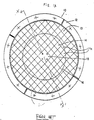
- In recent years, a so-called laminate tile pole piece has been developed for an MRI, see for example JP-A02-184002. In view of such development, a plan view of the laminate tile pole piece is shown in Figure 1A and a side view is shown in Figure 1B. The
pole piece 10 comprises a soft iron circular base plate 11, asoft iron ring 12 around the circumference of the base 11 for directing the magnetic flux into the gap between magnets, softferrite laminate tiles soft iron core 15 for mounting a gradient magnetic coil. The laminate tiles 13, 14 and thecore 15 comprise the pole piece face. The laminate tiles 14 in the center of the base plate 11 have a greater thickness thanlaminate tiles 13 at the periphery of the base plate 11 to form aconvex protrusion 16. Theconvex protrusion 16 improves the uniformity of the magnetic field. - However, the prior art laminate tile pole piece has several disadvantages. First,
most laminate tiles ring 12 have a circular shape. Therefore, in order to fit square or rectangular tiles into a circular opening, edge filler tiles 13A are required. As shown in Figure 1A, each edge filler tile 13A has a unique, odd shape to allow theperipheral tiles 13 to completely fill the circular base 11 andring 12. Each edge filler tile 13A must be formed separately fromother tiles 13 to create its unique shape. This increases process costs and complexity. - Second, the
protrusion 16 also has a circular shape, as shown in Figure 1A. Therefore, in order to arrange the square or rectangularcentral tiles 14 in a circle,edge filler tiles 14A are required, as shown in Figures 1A and 1 B. Theedge filler tiles 14A also have a unique, odd shape to allowcentral tiles 14 to form acircular protrusion 16. Furthermore, in order to allowcentral tiles 14 to fit with theperipheral tiles 13 without leaving gaps,edge filler tiles 14A also must have two different thicknesses, as shown in Figure 18. Each uniquely shapededge filler tile 14A must also be formed separately from othercentral tiles 14. This further increases process costs. - Third, the prior art methods of attaching
individual laminate tiles protrusion 16 by manually stackingtiles 14 onto a base 11 because of human error. Therefore, different pole pieces manufactured by the prior art method suffer from poor reproducibility and have different performance characteristics due to a variance in the height of the protrusion. - In view of the foregoing, it would be desirable to decrease the manufacturing process cost and complexity by forming a laminated tile pole piece that does not contain oddly shaped edge filler tiles.
- The present invention provides a pole piece for a magnetic resonance imaging (MRI) system. The pole piece comprises a plurality of trapezoid or annular sector shaped tiles arranged in a plurality of concentric annular arrays.
- The invention will now be described in greater detail, by way of example, with reference to the drawings, in which:-
- Figure 1A is a plan view of a prior art pole piece.
- Figure 1B is a side cross sectional view of a prior art pole piece across line X-X' in Figure 1A.
- Figure 2A is a perspective view of a laminate tile arrangement according to the first embodiment of the current invention.
- Figure 2B is a plan view of a laminate tile arrangement according to the first embodiment of the current invention.
- Figure 2C is a side cross sectional view taken along line C-C' in Figure 2B of a laminate tile arrangement according to the first embodiment of the current invention.
- Figures 3A and 3B are side cross sectional views of MRI systems.
- Figure 4A is a plan view of a mold according to the present invention. -
- Figure 4B is a side cross sectional view of the mold along line A-A' in Figure 4B.
- Figure 4C is a schematic of the pole piece and mold cavity surface contours.
- Figure 4D is a side cross sectional view of a mold according to an alternative embodiment of the present invention.
- Figure 5A is a side cross sectional view of the mold filled with laminate tiles according to the present invention.
- Figure 5B is a close up side cross sectional view of a section of Figure 5A.
- Figure 5C is a side cross sectional view of a laminate tile according to another embodiment of the present invention.
- Figure 6A is side cross sectional view of a laminate tile pole piece according the present invention.
- Figure 6B is a dose up side cross sectional view of a section of Figure 6A.
- Figure 7A is a plan view of a laminate tile arrangement according to the second embodiment of the current invention.
- Figure 7B is a side cross sectional view of a section of Figure 7A.
- Figure 7C is a plan view of a laminate tile according to the second embodiment of the current invention.
- Figure 7D is a side cross sectional view of a laminate tile according to the second embodiment of the current invention.
- Figure 8 is a perspective view of a laminate tile according to the third embodiment of the current invention.
- Figures 9A and 9B are side cross sectional views of MRI systems according the third embodiment of the current invention.
- Figures 10A and 10B are perspective views of laminate tiles according to the fourth embodiment of the current invention.
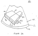
- Figure 2A shows a perspective view of a cut away portion of a
pole piece 50 comprising apole piece base 51 having a first surface 40 and asecond surface 41. Polepiece laminate tiles 42 are attached to the first surface 40 of thebase 51. Thetiles 42 may be attached to thebase 51 by epoxy, glue and / or bolts. Each laminate tile comprises interposed plural metal layers, shown as 21, 22, 23, and adhesive layers, shown as 31, 32. Eachlaminate tile 42 actually contains 100 to 10,000 metal layers, where each metal layer is preferably less than 0.1mm thick less than 5 mils thick). Each tile is 0.2 to 250 mm thick (0.1 to 10 inches) and 10 to 800 mm (1 to 30 inches) wide. For example, each tile is about 200mm (8 inches) wide in its middle and 25 mm (1 inch) thick, and contains 1000 0.2 mm (1 mil) thick metal layers. However, the tiles and the metal layers may have other dimensions based on the required end use. Furthermore, each tile may alternatively comprise a solid metal block or bar instead of metal layer laminates. - The
laminate tiles 42 are preferably fabricated from amorphous metal layers. However, the metal does not have to be amorphous and may have a crystalline structure. The metal may comprise steel, iron, silicon steel or iron (i.e. non-oriented silicon steel), nickel steel or iron, permendur (FeCoV), nickel chromium steel or iron, aluminum steel or iron, aluminum chromium steel or iron or any other low coercivity material. Furthermore, thepole pieces 50 according to the current invention may compriselaminate tiles 42 made from different metals listed above. In other words, adjacent tiles may comprise different metals. - The
laminate tiles 42 preferably have a trapezoidal shape. However, laminate tiles may have an annular sector shape. An annular sector is a trapezoid that has a concave top orshort side 43 and a convex bottom orlong side 44. Thetrapezoidal laminate tiles 42 may be manufactured by adhering plural metal sheets with an adhesive and subsequently cutting the laminate sheets into trapezoidal tiles. - As shown in Figures ,2B and 2C, the circular
pole piece base 51 contains asupport ring 52 for containinglaminate tiles 42 and for directing the magnetic flux into a gap between magnets. The entirecircular base 51 and thering 52 are filled in withtrapezoidal laminate tiles 42. Thebase 51 andring 52 are sometimes called a "pole shoe." Alternatively, thering 52 is sometimes called an "edge shim." Figure-2B shows a plan view of thepole piece 50, while Figure 2C shows a cross sectional view taken along line C-C' in Figure 2B. The laminate tiles are arranged in concentric annular arrays or rings 53 to 62. The advantage of the trapezoidal or annular sector shape of thelaminate tiles 42 becomes apparent from Figure 2B. All laminate tiles may have the same size and shape. Therefore, no oddly shaped edge filler tiles are necessary to fill thebase 51 and thering 52. The cost and complexity of the method of assembling the laminate tile pole piece is thus reduced. - For example, the concentric tile annular arrays 53-57 near the center of the base 51 may have a larger thickness (i.e. height as measured from the base 51) than concentric tile
annular arrays base 51. The protrusion also does not require oddly shaped edge filler tiles. Optionally, the peripheral concentricannular arrays 59 and 62 may also have a larger thickness than peripheralannular arrays pole piece 50. Alternatively, the centralannular array 53 may be an iron core for mounting a gradient magnetic coil. - Furthermore, the annular arrays may be formed by stacking
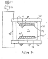
plural laminate tiles 42 on each other. The thicker concentric annular arrays may comprise more stacked laminate tiles than the thinner annular arrays. The space between the top of the polepiece support ring 52 and the laminate tiles may optionally be filled by passive shims. - Embodiments of magnetic field generating devices used for magnetic resonance imaging, MRI, ("MRI system") according to the present invention are shown in Figures 3A and 3B. The MRI system shown in Figure 3A has two plate yokes 71A and 71B and at least two, and preferably four columnar yokes 71C and 71 D. Alternatively, an MRI system with a single "C" shaped yoke 71 may be used as shown in Figure 3B. The MRI systems contain
magnets 72, 72' secured to yoke surfaces, pole piece bases 51, 51' and support rings 52, 52' secured to themagnets 72, 72' and laminatetile pole pieces 74, 74' secured to the pole piece bases and support rings. Agap 73 is formed between the pole pieces. A body part to be imaged is inserted into thegap 73. - The
magnets 72, 72' may comprise permanent magnets such as RFeB, RCoFeB or SmCo magnets, or electromagnetic magnets, such as a conductive or superconductive coil wrapped around a core. The MRI systems may also optionally contain gradient coils or shims shown as 75, 75' in Figures 6A and 6B. Furthermore, the MRI systems may optionally contain an insulating, low magnetic permeability layer, such as Bakelite, synthetic resin, wood, or ceramic, between the base and the laminate tiles to reduce the remnant magnetism in the pole pieces. - The MRI systems also may contain
electronics 76 and adisplay 77. Theelectronics 76 may comprise a control system, a transmitter, a receiver, an imager and / or a memory. - The optimum contour of the laminate tile pole pieces is determined by a simulation of the magnetic flux between the
top magnet 72 andbottom magnet 73. For example, the simulation may comprise a conventional finite element analysis method. The optimum height for each concentric annular array pole piece array 53-62 is determined from the simulation. - The laminate
tile pole piece 50 containing the concentric annular arrays is preferably manufactured using a mold and a molding method of the present invention. An embodiment of themold 100 is shown in Figures 4A and 4B. Figure 4B is a cross sectional view taken along line A-A' in Figure 4A. The mold contains abottom surface 101, aside surface 102 and acover plate 103. The mold further contains one or moreepoxy inlet openings 104 and one or moreair outlet openings 105. The opening(s) 104 is preferably made in thebottom mold surface 101 and the opening(s) 105 is preferably made in thecover plate 103. Thebottom mold surface 101 andcover plate 103 are preferably attached to theside wall 102 bybolts 106. However, thebottom surface 101 and theside surface 102 may alternatively comprise a unitary body and thecover plate 103 may be attached to theside wall 102 by other ways, such as a latch. Themold 100 has optional handles 107. - The mold preferably contains a non-uniform cavity surface contour. Preferably, the non-uniform contour is established by attaching spacers to the mold cavity
bottom surface 101. Preferably, the spacers form a plurality of concentric annular arrays 153 -162 around the circularbottom mold surface 101. The spacers 153-162 may be attached to themold cavity surface 101 byscrews 108 or by glue. Preferably the spacers have a cylindrical shape. However, the spacers may have any other shape. - As shown in Figure 4B, spacers in different concentric annular arrays 153 - 162 have a different height or thickness. Preferably there are as many spacers 153-162 as there are
laminate tiles 42 in the pole piece. Each spacer corresponds to a particular pole piece tile. The spacer surface in the mold forms a substantially inverse contour of the pole piece concentric annular tile array contour. In other words, if the pole piece annular array, such as tile array 62, has a large height or thickness, then the corresponding spacer array in the mold, such asspacer array 162 has a small height or thickness. If the pole piece annular array, such astile array 61, has a small height or thickness, then the corresponding spacer array in the mold, such as spacer array 161 has a large height or thickness. "Substantially inverse" means that the spacer contour may differ from the tile contour. For example, the tiles are attached to each other by an epoxy adhesive, while there may be gaps 109 between the spacers. Thus, the spacer contour also contains the gaps 109, while the tile contour does not contain the thin protrusions that would correspond to the gaps. Furthermore, there may be other slight vertical and horizontal variations in the contours. - Therefore, the contour of the non-uniform
mold cavity surface 110 is an inverse of a laminate tile pole piece contour 114, as shown in Figure 4C. The contour of the laminate tile pole piece is determined by performing simulation of a magnetic flux density between the MRI system magnets for different tile contours and then choosing the tile contour 114 which produces the optimum magnetic flux between the MRI system magnets. The magnetic flux lines from a finite element simulation of a field between two hypothetical MRI magnets are superimposed on the plan view of the mold in Figure 4A. - Alternatively, the non-uniform mold cavity surface contour may be made without using spacers 153-162, as shown in Figure 4D. In Figure 4D, the mold cavity surface itself is irregularly shaped to form a
non-uniform contour 110. Thecontour 110 comprises protrusions 111 and recesses 112. The protrusions 111 form plural concentric annular arrays whose contour is the substantial inverse of the pole piece tile contour. As with the mold shown in Figure 4B, each protrusion 111 should correspond to anindividual tile 42 of the pole piece. - A method of making the laminate tile pole piece according to the present invention is shown in Figures 5 and 6. The mold cavity and the spacers are first coated with a release agent.
Laminate tiles 42 are then placed into the mold cavity in concentric annular tile arrays 53-62, as shown in Figure 5A. The tiles are stacked on top of the corresponding concentric annular spacer arrays 153 -162. Of course, the spacers may be replaced by the protrusions of Figure 4C. Each tile should overlie one spacer, as shown in Figure 5B. The height of each tile and spacer stack should equal to the height of the mold cavity, such that the top surface of the tile arrays 53-62 is level with the top of the mold cavity. All variations as a result of tile height tolerances are taken as a small gap near the top of themold cover plate 103. Alternatively, each tile may be attached to its respective spacer withadhesive tape 123, as shown in Figure 5C. - The mold is then covered with the
cover plate 103 and an adhesive substance is introduced into the mold through theinlet opening 104. The adhesive substance is preferably a synthetic epoxy resin. The epoxy does not becomes attached to the mold cavity and the spacers because they are coated with the release agent. The epoxy permeates between the individual tiles and forces out any air trapped in the mold through outlet opening(s) 105. The epoxy 113 binds the individual tiles into aunitary body 120 comprising concentric annular tile arrays 53-62 of different height. Alternatively, the epoxy may be introduced through thetop opening 105 or through both top and bottom openings. - The
mold cover plate 103 is taken off the mold and theunitary tile body 120 is removed from themold 100. Theunitary body 120 is then attached with its flat (top) side to thepole piece base 51 andring 52, as shown in Figures 6A and 6B. Thebase 51,ring 52 and the unitary tile body comprise thepole piece 50. Theunitary tile body 120 may be attached to thebase 51 by epoxy, glue and / or bolts. - The second embodiment of the present invention is shown in Figures 7A to 7D. In the second embodiment, at least one
tile 42 contains acavity 121 in its face, as shown in Figures 7A and 7C. The cavity may be formed by introducing the epoxy 113 into themold 110 at high pressure. The high pressure epoxy flows over the concentric annular tile arrays 53-62 and presses the tile arrays against the cylindrical spacers 153-162 or protrusions 111 in the mold cavity. Each spacer or protrusion has a smaller surface area than the area of the corresponding tile. Therefore, pressure of the comparably softer tiles against the spacers orprotrusions forms cavities 121 in the tiles, as shown in Figures 7A - 7B. The cavities may be filled by passive shims or small permanent magnets. - In Figure 2A, the laminate layers are laminated along the height or thickness direction of the
laminate tile 42. However, in a third embodiment of the present invention, the laminate layers 91, 92, 93, 94 are stacked or laminated along the width of thelaminate tile 42", as shown in Figure 8.Laminate tile 42" may be produced by forming a thick stack or coil of epoxy bound metal layers, cutting a tile from the stack or coil and turning the tile on its side. -
Laminate tile 42" is mounted on thepole piece base 51 with the laminating direction perpendicular to the direction of the magnetic flux (i.e. perpendicular to an imaginary line between the bottom magnet 72' and the top magnet 72) as shown in Figure 9A. In other words, the laminating direction is parallel to the plane of the concentric annular tile arrays. The advantage of the this embodiment is increased stability of the magnetic field and a decrease in eddy currents and hysteresis effects. Alternatively, thelaminate tile 42" may be mounted on the edge of anotherpole piece member 90 to reduce sideways magnetic flux leakage, as shown in Figure 9B.Member 90 may itself comprise multiplelaminate tiles 42 with layers laminated in a direction parallel to the direction of the magnetic flux. In other words, the laminating direction is perpendicular to the laminating direction oftiles 42" and perpendicular to the plane of the concentric annular tile arrays). - In a fourth embodiment of the present invention, laminate tiles whose laminating directions are different by 90 degrees may be attached to each other. Such an arrangement improves the uniformity of the magnetic field in the
gap 73. For example, alaminate tile 42 may be attached tolaminate tile 42" to form a combinedtile 91 as shown in Figure 10A. Alternatively, twotiles 42" may be attached to form a combined tile 91' as shown in Figure 10B. Of course twotiles 42 may also be attached with their laminating directions inclined by 90 degrees to each other. The combinedtiles 91 and 91' may be attached to thepole piece base 51 with any surface facing theMRI system gap 73. Combinedtiles 91 and 91' may also comprise individual tiles made from different metals listed above. - The laminate tiles were described as being suitable for an MRI system pole piece. However, other uses for the laminate tiles and the laminate tile fabrication method are within the scope of the current invention. The mold may also be used to manufacture unitary bodies for uses other than an MRI system pole piece. Furthermore, in some applications, it may be advantageous to use laminate bars instead of trapezoidal tiles. In this case, the laminate bars may be considered "laminate tiles" for the purposes of this invention.
Claims (26)
- A pole piece (50) for a magnetic resonance imaging (MRI) system, comprising:a first face of the pole piece adapted to be placed toward an imaging gap located between MRI system magnets, characterized by:a plurality of trapezoid or annular sector shaped tiles (42) arranged in a plurality of concentric annular arrays (53-62) in the first face of the pole piece (50).
- The pole piece of claim 1 wherein:the tiles (42) comprise a plurality of laminated layers; anda height of a first concentric annular array is greater than a height of a second concentric annular array.
- The pole piece of claim 2, wherein:the plurality of concentric annular arrays (53-62) comprise a unitary tile body connected to a base;a first tile is separated from a second tile by an adhesive layer:at least one tile contains a cavity in the first face; and the cavity is filled by a shim or an auxiliary magnet over the first face.
- The pole piece of claim 1 wherein the pole piece (50) is adapted to be placed adjacent to a first magnet of a magnetic resonance imaging (MRI) system, the plurality of trapezoid or annular sector shaped tiles (42) being arranged in a plurality of concentric annular arrays (53-62) in a plane adapted to be perpendicular to a direction of a magnetic field of the first magnet.
- The pole piece of claim 4, wherein the tiles (42) are arranged In a plane adapted to be perpendicular to a direction of a magnetic field of the first magnet
- The pole piece of claim 5, wherein:the tiles (42) comprise a plurality of laminated layers (21, 22, 23, 31, 32); anda height of a first concentric annular array is greater than a height of a second concentric annular array.
- The pole piece of claim 6, wherein:the plurality of concentric annular arrays (53-62) comprise a unitary tile body connected to a base; anda first tile (42) is separated from a second tile (42) by an adhesive layer.
- The pole piece of claim 1, comprising:the first face is a first surface;a second surface of the pole piece (50) adapted to be connected to and parallel to a pole piece base;a side surface of the pole piece; andwherein the plurality of trapezoid or annular sector shaped tiles (42) arranged In a plurality of concentric annular arrays (53-62) in a plane parallel to the first and second surfaces of the pole piece.
- The pole piece of claim 8, wherein the tiles comprise a plurality of laminated layers (21, 22, 23, 31, 32).
- The pole piece of claim 8, wherein a height of a first concentric annular array is greater than a height of a second concentric annular array.
- The pole piece of claim 10, wherein the surface contour of the plurality of concentric annular arrays (53-62) forms an inverse contour of a non-uniform mold cavity surface.
- The pole piece of claim 8, wherein:the plurality of concentric annular arrays (53-62) comprise a unitary tile body (120);the unitary tile body (120) is connected to the pole piece base (51); anda portion of the pole piece base (51) comprises the side surface of the pole piece.
- The pole piece of claim 8, wherein a first tile (42) is separated from a second tile (42) by an adhesive layer.
- The pole piece of claim 9, wherein the laminating direction of the tile layers is parallel to a plane of each concentric annular array (53-62).
- The pole piece of claim 9, wherein the laminating direction of the tile layers perpendicular to a plane of each concentric annular array (53-62).
- The pole piece of claim 9, further comprising a first tile containing laminated layers attached over a second tile containing laminated layers to form a combined laminate tile.
- The pole piece of claim 9, wherein the layer laminating direction of the first tile is perpendicular to the layer laminating direction of the second tile.
- The pole piece of claim 8, wherein at least one tile contains a cavity in the tile face.
- The pole piece of claim 18, wherein at least one cavity is filled by a shim or an auxiliary magnet
- The pole piece of claim 9, further comprising:a yoke;a first magnet containing a first side attached to a first portion of the yoke and a second side attached to the base of the laminate file pole piece;a second magnet attached to a second portion of the yoke;a second pole piece comprising a plurality of second tiles attached to the second magnet and facing the laminate tile pole piece; andwherein the laminate tile pole piece and the second pole piece are arranged on opposite sides of the imaging gap.
- The pole piece of claim 8, wherein the arrays are arranged in a plane parallel to the first and second surfaces of the pole piece.
- An MRI system, comprising a first and a second pole piece (50, 74) according to claim 1, further comprising:a yoke (74A-D);a first magnet (72) containing a first side attached to a first portion of the yoke, the first pole piece (50, 74) having a second face attached to a second side of the first magnet;a second magnet (72') containing a first side attached to a second portion of the yoke;a second pole piece (74') having a first surface attached to a second side of the second magnet, wherein the imaging gap (73) is formed between the first face of the first pole piece and a second surface of the second pole piece such that the first and the second pole pieces are arranged on opposite sides of the imaging gap.
- The MRI system of claim 22, wherein the second pole piece comprises a plurality of trapezoid or annular sector shaped tiles (42) arranged In a plurality of concentric annular arrays in the second surface of the second pole piece.
- The MRI system of claim 23, wherein:the tiles of the first and the second pole piece comprise a plurality of laminated layers; anda height of a first concentric annular array is greater than a height of a second concentric annular array in the first and the second pole pieces.
- The MRI system of claim 24, wherein:the plurality of concentric annular arrays of the first pole piece comprise a unitary tile body connected to a base;the base comprises the first side of the first pole piece that is attached to the second side of the magnet; and a first tile of the plurality of tiles is separated from a second tile of the plurality of tiles by an adhesive layer.
- The MRI system of claim 22, wherein:at least one tile contains a cavity in the tile face in the second surface of the first pole piece; andthe cavity is filled by a shim or an auxiliary magnet over the second surface of the pole piece.
Applications Claiming Priority (2)
| Application Number | Priority Date | Filing Date | Title |
|---|---|---|---|
| US198507 | 1998-11-24 | ||
| US09/198,507 US6259252B1 (en) | 1998-11-24 | 1998-11-24 | Laminate tile pole piece for an MRI, a method manufacturing the pole piece and a mold bonding pole piece tiles |
Publications (3)
| Publication Number | Publication Date |
|---|---|
| EP1004889A2 EP1004889A2 (en) | 2000-05-31 |
| EP1004889A3 EP1004889A3 (en) | 2000-08-23 |
| EP1004889B1 true EP1004889B1 (en) | 2006-03-15 |
Family
ID=22733655
Family Applications (1)
| Application Number | Title | Priority Date | Filing Date |
|---|---|---|---|
| EP99309392A Expired - Lifetime EP1004889B1 (en) | 1998-11-24 | 1999-11-24 | Laminate tile pole piece for an MRI magnet, a method of manufacturing the pole piece and a mold for bonding pole piece tiles |
Country Status (4)
| Country | Link |
|---|---|
| US (3) | US6259252B1 (en) |
| EP (1) | EP1004889B1 (en) |
| JP (1) | JP4445078B2 (en) |
| DE (1) | DE69930356T2 (en) |
Families Citing this family (45)
| Publication number | Priority date | Publication date | Assignee | Title |
|---|---|---|---|---|
| US6331363B1 (en) | 1998-11-06 | 2001-12-18 | Honeywell International Inc. | Bulk amorphous metal magnetic components |
| US6346337B1 (en) | 1998-11-06 | 2002-02-12 | Honeywell International Inc. | Bulk amorphous metal magnetic component |
| US6348275B1 (en) | 1998-11-06 | 2002-02-19 | Honeywell International Inc. | Bulk amorphous metal magnetic component |
| GB2355800B (en) * | 1999-10-29 | 2004-10-27 | Oxford Magnet Tech | Improved magnet |
| US6842002B2 (en) * | 2000-01-19 | 2005-01-11 | Millennium Technology, Inc. | C-shaped magnetic resonance imaging system |
| JP3705995B2 (en) * | 2000-04-19 | 2005-10-12 | ジーイー・メディカル・システムズ・グローバル・テクノロジー・カンパニー・エルエルシー | Gradient coil manufacturing method, gradient coil, and magnetic resonance imaging apparatus |
| US6552639B2 (en) | 2000-04-28 | 2003-04-22 | Honeywell International Inc. | Bulk stamped amorphous metal magnetic component |
| US6825758B1 (en) | 2000-06-26 | 2004-11-30 | Nokian Tyres Plc | System for detecting and communicating operational characteristics of tires telecommunicationally and a method therefor |
| US6822449B1 (en) | 2000-11-22 | 2004-11-23 | Fonar Corporation | Ferromagnetic frame with laminated carbon steel |
| US7248137B1 (en) | 2000-11-22 | 2007-07-24 | Fonar Corporation | Magnet structure |
| US7271689B1 (en) | 2000-11-22 | 2007-09-18 | Fonar Corporation | Magnet structure |
| US6982620B1 (en) * | 2000-11-22 | 2006-01-03 | Fonar Corporation | Magnet structure |
| US7463129B1 (en) | 2000-11-22 | 2008-12-09 | Fonar Corporation | Magnet structure |
| US6970061B1 (en) * | 2000-11-22 | 2005-11-29 | Fonar Corporation | Magnet structure |
| JP3535107B2 (en) * | 2001-03-02 | 2004-06-07 | 株式会社日立製作所 | Magnetic pole and magnet device using the same |
| US6662434B2 (en) | 2001-04-03 | 2003-12-16 | General Electric Company | Method and apparatus for magnetizing a permanent magnet |
| US6518867B2 (en) * | 2001-04-03 | 2003-02-11 | General Electric Company | Permanent magnet assembly and method of making thereof |
| US7084632B2 (en) * | 2002-04-01 | 2006-08-01 | Shenyang Neusoft Bopu Nmr Tech Co., Ltd. | Permanent magnet for magnet resonance |
| US6984982B2 (en) * | 2002-07-29 | 2006-01-10 | Ge Medical Systems Global Technology Company Llc | Method and system for shimming an MRI magnet assembly |
| US6873239B2 (en) | 2002-11-01 | 2005-03-29 | Metglas Inc. | Bulk laminated amorphous metal inductive device |
| US6737951B1 (en) | 2002-11-01 | 2004-05-18 | Metglas, Inc. | Bulk amorphous metal inductive device |
| US7242191B2 (en) * | 2002-11-25 | 2007-07-10 | General Electric Company | Cold mass support structure and helium vessel of actively shielded high field open MRI magnets |
| US6825666B2 (en) * | 2002-12-23 | 2004-11-30 | General Electric Company | Pole face for permanent magnet MRI with laminated structure |
| US6859123B2 (en) * | 2003-04-03 | 2005-02-22 | Ge Medical Systems Global Technology Company, Llc | Methods and apparatus for positioning permanent magnetic blocks |
| US7235910B2 (en) | 2003-04-25 | 2007-06-26 | Metglas, Inc. | Selective etching process for cutting amorphous metal shapes and components made thereof |
| CN100434928C (en) * | 2003-05-23 | 2008-11-19 | 西门子(中国)有限公司 | Magnetic field generating system used for magnetic resonance equipment |
| CN100504432C (en) * | 2003-05-23 | 2009-06-24 | 西门子(中国)有限公司 | Magnetostatic field regulating method in magnetic resonance equipment and magnetostatic field generating apparatus thereof |
| US20050062572A1 (en) * | 2003-09-22 | 2005-03-24 | General Electric Company | Permanent magnet alloy for medical imaging system and method of making |
| US7148689B2 (en) * | 2003-09-29 | 2006-12-12 | General Electric Company | Permanent magnet assembly with movable permanent body for main magnetic field adjustable |
| US7423431B2 (en) * | 2003-09-29 | 2008-09-09 | General Electric Company | Multiple ring polefaceless permanent magnet and method of making |
| US7218195B2 (en) * | 2003-10-01 | 2007-05-15 | General Electric Company | Method and apparatus for magnetizing a permanent magnet |
| US6937018B2 (en) * | 2003-10-31 | 2005-08-30 | General Electric Company | Systems and methods for fabricating pole pieces for magnetic resonance imaging systems |
| US6956375B2 (en) * | 2004-01-09 | 2005-10-18 | General Electric Company | Magnetic resonance imaging magnetic field generator |
| US7631411B2 (en) * | 2004-06-28 | 2009-12-15 | General Electric Company | Method of manufacturing support structure for open MRI |
| US7319326B2 (en) * | 2004-09-23 | 2008-01-15 | University Of New Brunswick | Sensor and magnetic field apparatus suitable for use in for unilateral nuclear magnetic resonance and method for making same |
| JP2006149722A (en) * | 2004-11-30 | 2006-06-15 | Ge Medical Systems Global Technology Co Llc | Magnet system and magnetic resonance imaging apparatus |
| US8237440B2 (en) * | 2005-09-23 | 2012-08-07 | University Of New Brunswick | Magnetic field generator suitable for unilateral nuclear magnetic resonance and method for making same |
| US7400147B2 (en) * | 2005-11-03 | 2008-07-15 | Uri Rapoport | Self-fastening cage surrounding a magnetic resonance device and methods thereof |
| US8593144B2 (en) * | 2006-11-24 | 2013-11-26 | University Of New Brunswick | Magnet array |
| JP4668238B2 (en) * | 2007-05-08 | 2011-04-13 | 住友重機械工業株式会社 | Cold storage refrigerator and pulse tube refrigerator |
| CN102316798A (en) * | 2008-12-18 | 2012-01-11 | 古鲁姆·泰克勒马林 | Compact inhomogeneous permanent magnetic field generator for magnetic resonance imaging |
| JP5349177B2 (en) * | 2009-07-09 | 2013-11-20 | 株式会社東芝 | Magnetic resonance imaging system |
| CA2960189C (en) | 2014-09-05 | 2021-11-23 | Hyperfine Research, Inc. | Low field magnetic resonance imaging methods and apparatus |
| US10539637B2 (en) | 2016-11-22 | 2020-01-21 | Hyperfine Research, Inc. | Portable magnetic resonance imaging methods and apparatus |
| US10627464B2 (en) | 2016-11-22 | 2020-04-21 | Hyperfine Research, Inc. | Low-field magnetic resonance imaging methods and apparatus |
Family Cites Families (21)
| Publication number | Priority date | Publication date | Assignee | Title |
|---|---|---|---|---|
| GB1004888A (en) * | 1964-01-24 | 1965-09-15 | Shibata Fukuo | Electric motor controlling system |
| US3940528A (en) | 1965-05-14 | 1976-02-24 | Roberts Arthur H | Rigid plastics tile with textured surface |
| JPS55106058A (en) * | 1979-02-06 | 1980-08-14 | Toshiba Corp | Production of stator core |
| JPS55121622A (en) * | 1979-03-14 | 1980-09-18 | Toshiba Corp | Manufacture of c-cut core of wound-core |
| US4496395A (en) | 1981-06-16 | 1985-01-29 | General Motors Corporation | High coercivity rare earth-iron magnets |
| US4540453A (en) | 1982-10-28 | 1985-09-10 | At&T Technologies | Magnetically soft ferritic Fe-Cr-Ni alloys |
| US4707313A (en) * | 1986-07-02 | 1987-11-17 | A. O. Smith Corporation | Method of making a laminated structure for use in an electrical apparatus |
| JPS63241905A (en) | 1987-03-27 | 1988-10-07 | Sumitomo Special Metals Co Ltd | Magnetic field generating equipment |
| JPH02184002A (en) * | 1989-01-10 | 1990-07-18 | Sumitomo Special Metals Co Ltd | Magnetic field generator for mri |
| JPH02246927A (en) * | 1989-03-20 | 1990-10-02 | Hitachi Medical Corp | Magnetic field generator for magnetic resonance imaging device |
| US5252924A (en) | 1991-11-18 | 1993-10-12 | Sumitomo Special Metals Co., Ltd. | Magnetic field generating apparatus for MRI |
| JP2808198B2 (en) | 1990-07-02 | 1998-10-08 | 住友特殊金属株式会社 | Magnetic field generator for MRI and its manufacturing method |
| EP0479514B1 (en) * | 1990-09-29 | 1998-07-01 | Sumitomo Special Metals Co., Ltd. | Magnetic field generating device used for MRI |
| JPH04307705A (en) * | 1991-04-04 | 1992-10-29 | Seiko Epson Corp | Magnetic-field generation device |
| JP2694092B2 (en) * | 1991-10-21 | 1997-12-24 | キヤノン株式会社 | Magnet roller, method for manufacturing the magnet roller, apparatus for manufacturing the magnet roller, developing unit, and copying apparatus including the developing unit |
| ATE167239T1 (en) | 1992-02-15 | 1998-06-15 | Santoku Metal Ind | ALLOY BLOCK FOR A PERMANENT MAGNET, ANISOTROPIC POWDER FOR A PERMANENT MAGNET, METHOD FOR PRODUCING THE SAME AND PERMANENT MAGNET |
| FI105293B (en) * | 1993-06-08 | 2000-07-14 | Picker Nordstar Oy | Polar shoe for magnetic resonance imaging |
| DE69419096T2 (en) | 1993-09-29 | 1999-10-28 | Oxford Magnet Tech | Magnetic resonance imaging enhancements |
| US5475355A (en) * | 1994-04-15 | 1995-12-12 | New York University | Method and apparatus for compensation of field distortion in a magnetic structure using spatial filter |
| JPH0831635A (en) | 1994-07-08 | 1996-02-02 | Sumitomo Special Metals Co Ltd | Mri magnetic field generating device |
| US6150819A (en) * | 1998-11-24 | 2000-11-21 | General Electric Company | Laminate tiles for an MRI system and method and apparatus for manufacturing the laminate tiles |
-
1998
- 1998-11-24 US US09/198,507 patent/US6259252B1/en not_active Expired - Fee Related
-
1999
- 1999-11-22 JP JP33078799A patent/JP4445078B2/en not_active Expired - Fee Related
- 1999-11-24 DE DE69930356T patent/DE69930356T2/en not_active Expired - Lifetime
- 1999-11-24 EP EP99309392A patent/EP1004889B1/en not_active Expired - Lifetime
-
2000
- 2000-12-18 US US09/738,838 patent/US6429761B2/en not_active Expired - Lifetime
- 2000-12-18 US US09/738,856 patent/US6694602B2/en not_active Expired - Fee Related
Also Published As
| Publication number | Publication date |
|---|---|
| EP1004889A2 (en) | 2000-05-31 |
| US20010005165A1 (en) | 2001-06-28 |
| DE69930356D1 (en) | 2006-05-11 |
| US6694602B2 (en) | 2004-02-24 |
| US20020021129A1 (en) | 2002-02-21 |
| DE69930356T2 (en) | 2007-03-01 |
| EP1004889A3 (en) | 2000-08-23 |
| US6429761B2 (en) | 2002-08-06 |
| JP2000157510A (en) | 2000-06-13 |
| US6259252B1 (en) | 2001-07-10 |
| JP4445078B2 (en) | 2010-04-07 |
Similar Documents
| Publication | Publication Date | Title |
|---|---|---|
| EP1004889B1 (en) | Laminate tile pole piece for an MRI magnet, a method of manufacturing the pole piece and a mold for bonding pole piece tiles | |
| EP0479514B1 (en) | Magnetic field generating device used for MRI | |
| EP0691548B1 (en) | Magnetic field generating device for use in MRI | |
| JP4039495B2 (en) | Magnetic field generator for MRI | |
| US5124651A (en) | Nuclear magnetic resonance scanners with composite pole facings | |
| EP0591542B1 (en) | Magnetic field generator for mri | |
| US5317297A (en) | MRI magnet with robust laminated magnetic circuit member and method of making same | |
| US20020180573A1 (en) | Permanent magnet assembly and method of making thereof | |
| JPH07163546A (en) | Magnetic resonance image forming device (mri) magnet | |
| US3735306A (en) | Magnetic field shim coil structure utilizing laminated printed circuit sheets | |
| EP2108974B1 (en) | Process for manufacturing pole pieces of nuclear magnetic resonance imaging magnets | |
| EP0213862A2 (en) | Magnet assembly for magnetic resonance imaging and method of manufacture | |
| JPH05182821A (en) | Magnetic field generator for mri | |
| JP3510544B2 (en) | Apparatus for forming a magnetic field in an air gap | |
| EP0541872B1 (en) | Magnetic field generating apparatus for MRI | |
| JP2649436B2 (en) | Magnetic field generator for MRI | |
| JP2649437B2 (en) | Magnetic field generator for MRI | |
| EP1447676B1 (en) | Circular pole piece and mri system | |
| JP4214736B2 (en) | Magnetic field generator for MRI | |
| USRE35565E (en) | Magnetic field generating apparatus for MRI | |
| JP3073933B2 (en) | Magnetic field generator for MRI | |
| JP3445303B2 (en) | Magnetic field generator for MRI | |
| JP3369653B2 (en) | Permanent magnet facing magnetic field generator | |
| US20230103189A1 (en) | Magnet with Multiple Discs | |
| US20210110966A1 (en) | Magnet with multiple discs |
Legal Events
| Date | Code | Title | Description |
|---|---|---|---|
| PUAI | Public reference made under article 153(3) epc to a published international application that has entered the european phase |
Free format text: ORIGINAL CODE: 0009012 |
|
| AK | Designated contracting states |
Kind code of ref document: A2 Designated state(s): DE GB NL |
|
| AX | Request for extension of the european patent |
Free format text: AL;LT;LV;MK;RO;SI |
|
| PUAL | Search report despatched |
Free format text: ORIGINAL CODE: 0009013 |
|
| AK | Designated contracting states |
Kind code of ref document: A3 Designated state(s): AT BE CH CY DE DK ES FI FR GB GR IE IT LI LU MC NL PT SE |
|
| AX | Request for extension of the european patent |
Free format text: AL;LT;LV;MK;RO;SI |
|
| 17P | Request for examination filed |
Effective date: 20010223 |
|
| AKX | Designation fees paid |
Free format text: DE GB NL |
|
| 17Q | First examination report despatched |
Effective date: 20021121 |
|
| GRAP | Despatch of communication of intention to grant a patent |
Free format text: ORIGINAL CODE: EPIDOSNIGR1 |
|
| GRAS | Grant fee paid |
Free format text: ORIGINAL CODE: EPIDOSNIGR3 |
|
| GRAA | (expected) grant |
Free format text: ORIGINAL CODE: 0009210 |
|
| AK | Designated contracting states |
Kind code of ref document: B1 Designated state(s): DE GB NL |
|
| REG | Reference to a national code |
Ref country code: GB Ref legal event code: FG4D |
|
| REF | Corresponds to: |
Ref document number: 69930356 Country of ref document: DE Date of ref document: 20060511 Kind code of ref document: P |
|
| PLBE | No opposition filed within time limit |
Free format text: ORIGINAL CODE: 0009261 |
|
| STAA | Information on the status of an ep patent application or granted ep patent |
Free format text: STATUS: NO OPPOSITION FILED WITHIN TIME LIMIT |
|
| 26N | No opposition filed |
Effective date: 20061218 |
|
| PGFP | Annual fee paid to national office [announced via postgrant information from national office to epo] |
Ref country code: GB Payment date: 20131127 Year of fee payment: 15 Ref country code: DE Payment date: 20131127 Year of fee payment: 15 |
|
| PGFP | Annual fee paid to national office [announced via postgrant information from national office to epo] |
Ref country code: NL Payment date: 20131126 Year of fee payment: 15 |
|
| REG | Reference to a national code |
Ref country code: DE Ref legal event code: R119 Ref document number: 69930356 Country of ref document: DE |
|
| REG | Reference to a national code |
Ref country code: NL Ref legal event code: V1 Effective date: 20150601 |
|
| GBPC | Gb: european patent ceased through non-payment of renewal fee |
Effective date: 20141124 |
|
| PG25 | Lapsed in a contracting state [announced via postgrant information from national office to epo] |
Ref country code: NL Free format text: LAPSE BECAUSE OF NON-PAYMENT OF DUE FEES Effective date: 20150601 |
|
| PG25 | Lapsed in a contracting state [announced via postgrant information from national office to epo] |
Ref country code: GB Free format text: LAPSE BECAUSE OF NON-PAYMENT OF DUE FEES Effective date: 20141124 Ref country code: DE Free format text: LAPSE BECAUSE OF NON-PAYMENT OF DUE FEES Effective date: 20150602 |