EP1005884A2 - Continuously rotating mechanisms - Google Patents
Continuously rotating mechanisms Download PDFInfo
- Publication number
- EP1005884A2 EP1005884A2 EP99309752A EP99309752A EP1005884A2 EP 1005884 A2 EP1005884 A2 EP 1005884A2 EP 99309752 A EP99309752 A EP 99309752A EP 99309752 A EP99309752 A EP 99309752A EP 1005884 A2 EP1005884 A2 EP 1005884A2
- Authority
- EP
- European Patent Office
- Prior art keywords
- link
- linkage
- links
- sub
- linkage system
- Prior art date
- Legal status (The legal status is an assumption and is not a legal conclusion. Google has not performed a legal analysis and makes no representation as to the accuracy of the status listed.)
- Withdrawn
Links
Images


Classifications
-
- E—FIXED CONSTRUCTIONS
- E04—BUILDING
- E04B—GENERAL BUILDING CONSTRUCTIONS; WALLS, e.g. PARTITIONS; ROOFS; FLOORS; CEILINGS; INSULATION OR OTHER PROTECTION OF BUILDINGS
- E04B1/00—Constructions in general; Structures which are not restricted either to walls, e.g. partitions, or floors or ceilings or roofs
- E04B1/343—Structures characterised by movable, separable, or collapsible parts, e.g. for transport
- E04B1/344—Structures characterised by movable, separable, or collapsible parts, e.g. for transport with hinged parts
- E04B1/3441—Structures characterised by movable, separable, or collapsible parts, e.g. for transport with hinged parts with articulated bar-shaped elements
-
- A—HUMAN NECESSITIES
- A63—SPORTS; GAMES; AMUSEMENTS
- A63F—CARD, BOARD, OR ROULETTE GAMES; INDOOR GAMES USING SMALL MOVING PLAYING BODIES; VIDEO GAMES; GAMES NOT OTHERWISE PROVIDED FOR
- A63F9/00—Games not otherwise provided for
- A63F9/06—Patience; Other games for self-amusement
- A63F9/08—Puzzles provided with elements movable in relation, i.e. movably connected, to each other
- A63F9/0803—Two-dimensional puzzles with slideable or rotatable elements or groups of elements, the main configuration remaining unchanged
- A63F9/0819—Two-dimensional puzzles with slideable or rotatable elements or groups of elements, the main configuration remaining unchanged with rotatable non-concentric discs, e.g. gear games
Definitions
- the invention disclosed is a unique type of linkage that is comprised of a multiplicity of links lying on different levels. These links form a chain or a matrix of interconnected four-bar linkages. I have discovered a novel arrangement of connections that allow the links in such a linkage to rotate continuously relative to one another, rather than having rotational limits.
- linkages are useful as toys or novelty items.
- the linkages can function as interactive educational tools, using the changing geometric patterns to reveal mathematical relationships.
- Other uses may include vehicles for rough terrain, where the linkage forms a unique tread that can move over rough surfaces.
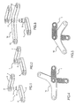
- FIG. 1 Shown in FIG. 1 is an exploded view of a link 1 that is made up of two sub-links 2 and 3.
- Sub-link 2 has a pivot 6 on one end, and a second pivot 5 on its other end. Attached to pivot 5 is an element 4 that provides means to make a rigid (non-rotatable) connection to sub-link 3.
- Sub-link 3 has a pivot 7 on one end and a cavity 8 which engages with element 4.
- sub-links 2 and 3 are shown rigidly attached together. It is seen that link 1 lies within two distinct planes and has a central pivot 5 that remains exposed between sub-links 2 and 3. Link 1 and others of its general type are thus hereinafter referred to as multi-level links. Pivots 6 and 7 lie at the extremities of link 1 and are hereinafter referred to as terminal pivots.
- FIG. 3 is an exploded view of link 1 with a second angulated link 10 lying between sub-links 2 and 3.
- Link 10 has a central pivot 11 and two terminal pivots 12 and 13.
- Link 10 may be pivotally attached to link 1 such that central pivot 11 is engaged with pivot 5.
- Link 10 and others of its general type are hereinafter referred to as planar links.
- FIG. 4 shows multi-level 1 and planar link 10 pivotally attached together.
- Link 1 is shown as a shaded element for clarity in the drawing.
- FIG. 5 shows links 1 and 10 rotated to a different position. It is seen that link 10 is capable of being rotated in a continuous fashion relative to link 1.
- FIG. 6 shows a linkage 15 consisting of multi-level link 1, planar link 10 and four other planar links 20, 30, 40 and 50.
- Links 20 and 30 are attached to one terminal pivot each of links 1 and 10, and are pivotally attached to each other, thereby forming a closed loop.
- links 40 and 50 are attached to one terminal pivot each of links 1 and 10, and are pivotally attached to each other, also forming a closed loop.
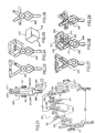
- FIG. 7 is a diagram of lines that connect pivots-centers of linkage 15 as shown in FIG. 6.
- the diagram may be seen to consist of two parallelograms 16 and 17.
- the parallelograms are seen to correspond to parallel four-bar linkages in the actual mechanism.
- FIGS. 8-11 show linkage 15 in various positions. It is seen that link 10 may be rotated a full 360 degrees relative to link 1 with no interference from attached links 20, 30, 40 and 50.
- FIG. 12 is a diagram that corresponds to lines connecting the pivots of linkage 15 as shown in FIG. 11. It is seen to consist of two quadrilaterals 18 and 19 which are parallelograms in this case.
- linkage 15 similarly constructed diagrams consist of two quadrilaterals, with link 10 forming a side of each of the quadrilaterals and a vertex of each quadrilateral.
- the arms of link 10 have been illustrated as extending at an obtuse angle with respect to each other. It is to be understood that link 10 would function the same if the arms were disposed at acute or right angles.
- sub-links 2 and 3 of link 1 can also be disposed at other than right angles with respect to each other.
- FIG. 13 is an exploded view of linkage which is comprised of three multi-level links, 110, 120 and 130 and three angulated planar links 140, 150, 160.
- Each central pivot of each multi-level link passes through a pivot of planar link 150, such that sub-links 112, 122 and 132 lie on one side of planar link 150 and sub-links 113, 123 and 133 lie on the other side of link 150.
- Planar link 140 is pivotally attached to one terminal pivot each of multi-level level links 110, 120 and 130.
- planar link 160 is pivotally attached to one terminal pivot each of multi-level level links 110, 120 and 130.
- FIG. 14 shows linkage 100 in assembled form.
- Each central pivot of multi-level links 110, 120 and 130 passes through and has a pivotal connection with planar link 150.
- Sub-links 112 and 113 are rigidly attached together to form multi-level link 110.
- sub-links 122, 123 and sub-links 132, 133 form multi-level links 120 and 130 respectively.
- FIG. 15 shows linkage 100 in a different position where planar link 150 has been rotated relative to multi-level link 120.
- FIG. 16 shows another rotational position of linkage 100.
- FIG. 17 is a diagram that corresponds to the lines connecting the pivots of linkage 100 as shown in FIG. 15. It is seen to consist of four quadrilaterals (parallelograms) 171, 172, 173 and 174.
- Links 140, 150 and 160 form a side and vertex of adjacent quadrilaterals.
- FIGS. 18 and 19 show other positions of linkage 100. Examining the five positions shown in FIGS. 14-19, it is seen that the rotation of planar link 150 relative to multi-level link 120 continues without interference through a complete 360 degree revolution.
- FIG. 20 is a diagram that corresponds to lines connecting the pivots of linkage 100 as shown in FIG. 19. It is seen to consist of four parallelograms 181, 182, 183 and 184. In fact, for all positions of linkage 100 similarly constructed diagrams are seen to consist of four parallelograms.
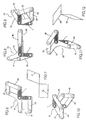
- FIG. 21 is an exploded view of a linkage 200, which consists of two planar links 210 and 211, as well as two multi-level links 220 and 230.
- Multi-level link 220 is comprised of two sub-links 221 and 222, and lies on either side of planar link 210;
- multi-level link 230 is comprised of sub-links 231 and 232 and lies on either side on planar link 211.
- FIG. 21 is yoke-like link 260 which spans the full thickness of linkage 200 and is pivotally attached to links 220 and 230.
- Link 260 is shown in two exploded parts for clarity in the drawings. Additionally, link 260 is pivotally attached to links 240 and 250 which serve to synchronize the motion of linkage 200.
- knobs 241, 251 which are used to drive the linkage. Knobs 241, 251 are connected to links 240, 250 by means of a multi-level link, which rotatably couples links 240, 250 to link 260 and rigidly couples links 240, 250 to links 241, 251. As is shown in FIG. 22, yoke 260 may include a handle portion 261 having an opening 262 (or other means) for attachment to an external object such as a key ring.
- FIG. 22 is a side view of linkage 200.
- Link 260 spans the full width of linkage 200.
- links of the same type as 260 shall be referred to as spanning links.
- FIG. 23 is a front view of linkage 200.
- FIG. 24 is a front view of linkage 200 in a different position.
- FIG. 25 shows a diagram of lines that correspond to the pivots of linkage 200. The diagram is seen to consist of three parallelograms 270, 271 and 272.
- FIG. 25 shows a front view of linkage 200 in yet another position.
- FIGS. 27, 28 and 29 are perspective views of linkage 200 in three positions corresponding to the front views 23, 24 and 26 respectively. As can be seen in FIG.
- link elements 240, 250 are V-shaped and have arms which are not linked to another element. Such arms add to the appearance of the overall device, but are not strictly needed for functionality.
- each side of yoke element 260 is shown as X-shaped, but could also take various other configurations depending on aesthetic or functional requirements.
- FIG. 30 shows an exploded view of a linkage 300 which consists of three planar links 340, 350 and 360, as well as three multi-level links 310, 320 and 330.
- Multi-level link 310 is comprised of two sub-links 311 and 312, and lies on either side of planar link 340;
- multi-level link 320 is comprised of sub-links 321 and 322 and lies on either side on planar link 350;
- multi-level link 330 is comprised of sub-lines 331 and 332 and lies on either side on planar link 360.
- a Y-shaped yoke link 390 which spans the full thickness of linkage 300 and is pivotally attached to links 310 and 330.
- Link 390 is shown in two exploded parts for clarity in the drawing.
- Link 390 is pivotally attached to links 370 and 380 which serve to synchronize the motion of linkage 300.
- gear elements 362, 363 which may be rigidly attached to links 370, 332 respectively.
- a third gear 361, which includes a knob 391 and which engages with gears 362, 363. These three gears serve to assist in synchronizing the movement of linkage 300.
- FIG. 31 shows a side view of linkage 300. Spanning link 390 is seen to span the full width of linkage 300.
- FIG. 32 shows a front view of linkage 300.
- FIG. 33 shows a front view of linkage 300 in a different position.
- FIG. 34 shows a diagram of lines that correspond to the pivots of linkage 300. The diagram is seen to consist of four parallelograms 391, 392, 393 and 394.
- FIG. 35 shows a front view of linkage 300 in yet another position.
- FIGS. 36, 37 and 38 show perspective views of linkage 300 in three positions corresponding to the front views 32, 33 and 35 respectively.
- the pawl shaped extensions 392, 393 of links such as 330, 370 serve to provide clearance for other link elements during rotation.
- FIG. 39 is an exploded view of a link 420 which is comprised of three sub-links 421, 422 and 423.
- Sub-link 421 has a pivot 424 to which an element 425 is attached, element 425 provides means to make a rigid connection to sub-link 422.
- sub-link 422 has a pivot 426 to which an element 427 is attached, element 427 providing means to make a rigid connection to sub-link 423.
- FIG. 40 shows link 420 in its assembled condition.
- Link 420 is a multi-level link having three distinct levels.
- FIG. 41 shows an exploded view of linkage 400. It consists of two Y-shaped planar links 440 and 450, as well as three multi-level links 410, 420 and 430.
- Multi-level link 410 is comprised of three sub-links 411, 412 and 413.
- Planar link 440 lies between sub-links 411 and 412.
- Planar link 450 lies between sub-links 412 and 413.
- multi-level links 420 and 430 comprised of sub-links 421, 422, 423 and 431, 432, 433 respectively, lie on either side of planar links 440 and 450.
- Y-shaped yoke link 460 which spans the full thickness of linkage 400 and is pivotally attached to links 410, 420 and 430.
- FIG. 42 shows a side view of linkage 400. Spanning link 460 may be seen to span the full width of linkage 400.
- FIG. 43 shows a front view of linkage 400.
- FIG. 44 shows a front view of linkage 400 in a different position.
- FIG. 45 shows a front view of linkage 400 in yet another position.
- FIGS. 46, 47 and 48 are perspective views of linkage 400 in three positions corresponding to front views 43, 44 and 45 respectively.
Abstract
Description
- The invention disclosed is a unique type of linkage that is comprised of a multiplicity of links lying on different levels. These links form a chain or a matrix of interconnected four-bar linkages. I have discovered a novel arrangement of connections that allow the links in such a linkage to rotate continuously relative to one another, rather than having rotational limits.
- When driven, such a linkage moves smoothly and synchronously, the links moving past one another on different levels. The patterns formed by the links as they change their configuration are surprising and aesthetically pleasing.
- Such linkages are useful as toys or novelty items. The linkages can function as interactive educational tools, using the changing geometric patterns to reveal mathematical relationships. Other uses may include vehicles for rough terrain, where the linkage forms a unique tread that can move over rough surfaces.
- Different types of linkage systems are found in the structures described in my prior U.S. patents, including U.S. Patent No. 4,942,700, issued July 24, 1990, entitled Reversibly Expandable Doubly-Curved Truss Structure; U.S. Patent No. 4,780,344, issued October 25, 1988, entitled Reversibly Expandable Three-Dimensional Structure; U.S. Patent No. 4,981,732, issued January 1, 1991, entitled Reversibly Expandable Structures; U.S. Patent No. 5,234,727, issued August 10, 1993, entitled Curved Pleated Sheet Structure; and U.S. Patent No. 5,024,031, issued June 18, 1991, entitled Radial Expansion/Retraction Truss Structure.
- For a better understanding of the invention, reference is made to the following drawings which are to be taken in conjunction with the detailed description to follow:
- FIGS. 1-2 show a basic element of the invention, a multi-level link;
- FIGS. 3-5 show a multi-level link assembled with another basic element, a planar link;
- FIG. 6 shows a first embodiment of the invention, a linkage consisting of two parallel assemblies capable of continuous rotation;
- FIG. 7 is a diagram of lines corresponding to the linkage;
- Figs 8-12 show other positions of the linkage;
- FIG. 13 is an exploded view of a second embodiment of the invention, a linkage having elements on five levels;
- FIGS. 14-20 show other positions of the linkage of FIG. 13;
- FIG. 21 shows an exploded view of a third embodiment of the invention having one link that spans the full thickness of the linkage;
- FIG. 22 shows a side view of the linkage of FIG. 21;
- FIGS. 23-26 show front views of the linkage of FIG. 21 in different positions;
- FIGS. 27-29 show perspective views of the linkage in different positions;
- FIG. 30 is an exploded view of a fourth embodiment of the invention having one link that spans the full thickness of the linkage;
- FIG. 31 shows a side view of the linkage of FIG. 30,
- FIGS. 32-35 show front views of the linkage of FIG. 30 in different positions;
- FIGS. 36-38 show perspective views of the linkage of FIG. 30 in different positions;
- FIGS. 39-40 are an exploded view of a fifth embodiment of the multi-level link of the present invention consisting of three sub-links lying on three levels;
- FIG. 41 shows an exploded view of a fifth embodiment of the invention having one link that spans the full thickness of the linkage;
- FIG. 42 is a side view of the linkage of FIG. 41;
- FIGS. 43-45 are a front view of the linkage of FIG. 41 in different positions; and
- FIGS. 46-48 are perspective views of the linkage of FIG. 41 in different positions.
-
- Shown in FIG. 1 is an exploded view of a
link 1 that is made up of twosub-links Sub-link 2 has apivot 6 on one end, and asecond pivot 5 on its other end. Attached topivot 5 is an element 4 that provides means to make a rigid (non-rotatable) connection tosub-link 3.Sub-link 3 has apivot 7 on one end and acavity 8 which engages with element 4. In FIG. 2sub-links link 1 lies within two distinct planes and has acentral pivot 5 that remains exposed betweensub-links Link 1 and others of its general type are thus hereinafter referred to as multi-level links.Pivots link 1 and are hereinafter referred to as terminal pivots. - FIG. 3 is an exploded view of
link 1 with a second angulatedlink 10 lying betweensub-links Link 10 has acentral pivot 11 and twoterminal pivots Link 10 may be pivotally attached tolink 1 such thatcentral pivot 11 is engaged withpivot 5.Link 10 and others of its general type are hereinafter referred to as planar links. FIG. 4 shows multi-level 1 andplanar link 10 pivotally attached together.Link 1 is shown as a shaded element for clarity in the drawing. FIG. 5shows links link 10 is capable of being rotated in a continuous fashion relative tolink 1. - FIG. 6 shows a
linkage 15 consisting ofmulti-level link 1,planar link 10 and four otherplanar links Links links links links - FIG. 7 is a diagram of lines that connect pivots-centers of
linkage 15 as shown in FIG. 6. The diagram may be seen to consist of twoparallelograms show linkage 15 in various positions. It is seen thatlink 10 may be rotated a full 360 degrees relative tolink 1 with no interference from attachedlinks linkage 15 as shown in FIG. 11. It is seen to consist of twoquadrilaterals linkage 15 similarly constructed diagrams consist of two quadrilaterals, withlink 10 forming a side of each of the quadrilaterals and a vertex of each quadrilateral. The arms oflink 10 have been illustrated as extending at an obtuse angle with respect to each other. It is to be understood thatlink 10 would function the same if the arms were disposed at acute or right angles. Simarlary,sub-links link 1 can also be disposed at other than right angles with respect to each other. - FIG. 13 is an exploded view of linkage which is comprised of three multi-level links, 110, 120 and 130 and three angulated
planar links planar link 150, such thatsub-links planar link 150 andsub-links link 150. Planar link 140 is pivotally attached to one terminal pivot each of multi-level level links 110, 120 and 130. Likewise,planar link 160 is pivotally attached to one terminal pivot each of multi-level level links 110, 120 and 130. - FIG. 14 shows
linkage 100 in assembled form. Each central pivot ofmulti-level links planar link 150.Sub-links multi-level link 110. Similarly sub-links 122, 123 andsub-links multi-level links linkage 100 in a different position whereplanar link 150 has been rotated relative tomulti-level link 120. FIG. 16 shows another rotational position oflinkage 100. FIG. 17 is a diagram that corresponds to the lines connecting the pivots oflinkage 100 as shown in FIG. 15. It is seen to consist of four quadrilaterals (parallelograms) 171, 172, 173 and 174.Links linkage 100. Examining the five positions shown in FIGS. 14-19, it is seen that the rotation ofplanar link 150 relative tomulti-level link 120 continues without interference through a complete 360 degree revolution. FIG. 20 is a diagram that corresponds to lines connecting the pivots oflinkage 100 as shown in FIG. 19. It is seen to consist of fourparallelograms linkage 100 similarly constructed diagrams are seen to consist of four parallelograms. - FIG. 21 is an exploded view of a
linkage 200, which consists of twoplanar links multi-level links Multi-level link 220 is comprised of twosub-links planar link 210;multi-level link 230 is comprised ofsub-links planar link 211. Also shown is FIG. 21 is yoke-like link 260 which spans the full thickness oflinkage 200 and is pivotally attached tolinks Link 260 is shown in two exploded parts for clarity in the drawings. Additionally, link 260 is pivotally attached tolinks linkage 200. Also shown areknobs Knobs links links links links yoke 260 may include a handle portion 261 having an opening 262 (or other means) for attachment to an external object such as a key ring. - FIG. 22 is a side view of
linkage 200.Link 260 spans the full width oflinkage 200. Hereinafter links of the same type as 260 shall be referred to as spanning links. FIG. 23 is a front view oflinkage 200. FIG. 24 is a front view oflinkage 200 in a different position. FIG. 25 shows a diagram of lines that correspond to the pivots oflinkage 200. The diagram is seen to consist of threeparallelograms linkage 200 in yet another position. FIGS. 27, 28 and 29 are perspective views oflinkage 200 in three positions corresponding to the front views 23, 24 and 26 respectively. As can be seen in FIG. 21, certain link elements such aselements yoke element 260 is shown as X-shaped, but could also take various other configurations depending on aesthetic or functional requirements. - FIG. 30 shows an exploded view of a
linkage 300 which consists of threeplanar links multi-level links Multi-level link 310 is comprised of twosub-links planar link 340;multi-level link 320 is comprised ofsub-links planar link 350;multi-level link 330 is comprised ofsub-lines planar link 360. Also shown in FIG. 30 is a Y-shaped yoke link 390 which spans the full thickness oflinkage 300 and is pivotally attached tolinks Link 390 is shown in two exploded parts for clarity in the drawing.Link 390 is pivotally attached tolinks linkage 300. Additionally shown aregear elements links third gear 361, which includes aknob 391 and which engages withgears linkage 300. - FIG. 31 shows a side view of
linkage 300. Spanninglink 390 is seen to span the full width oflinkage 300. FIG. 32 shows a front view oflinkage 300. FIG. 33 shows a front view oflinkage 300 in a different position. FIG. 34 shows a diagram of lines that correspond to the pivots oflinkage 300. The diagram is seen to consist of fourparallelograms linkage 300 in yet another position. FIGS. 36, 37 and 38 show perspective views oflinkage 300 in three positions corresponding to the front views 32, 33 and 35 respectively. The pawl shapedextensions - FIG. 39 is an exploded view of a
link 420 which is comprised of threesub-links Sub-link 421 has apivot 424 to which anelement 425 is attached,element 425 provides means to make a rigid connection tosub-link 422. Likewise, sub-link 422 has apivot 426 to which anelement 427 is attached,element 427 providing means to make a rigid connection tosub-link 423. FIG. 40 shows link 420 in its assembled condition.Link 420 is a multi-level link having three distinct levels. FIG. 41 shows an exploded view oflinkage 400. It consists of two Y-shapedplanar links multi-level links Multi-level link 410 is comprised of threesub-links sub-links sub-links multi-level links sub-links planar links linkage 400 and is pivotally attached tolinks - FIG. 42 shows a side view of
linkage 400. Spanninglink 460 may be seen to span the full width oflinkage 400. FIG. 43 shows a front view oflinkage 400. FIG. 44 shows a front view oflinkage 400 in a different position. FIG. 45 shows a front view oflinkage 400 in yet another position. FIGS. 46, 47 and 48 are perspective views oflinkage 400 in three positions corresponding to front views 43, 44 and 45 respectively. - The present invention has been described with respect to preferred embodiments. It is to be understood that modifications and variations to the illustrated structures may be resorted to, by persons skilled in the art, without departing from the scope of the invention, as set forth in the claims to follow.
Claims (23)
- A linkage comprising at least six links and at least seven pivot connections, all axes of said pivots being parallel to one another,wherein a diagram of lines connecting the centers of said pivots drawn in a plane orthogonal to the axes of the pivots forms at least two parallelograms such that each parallelogram shares at least one vertex with another parallelogram,wherein each parallelogram corresponds to a parallel four-bar linkage, and each shared vertex in the diagram corresponds to a pivot connection between at least two links, each of which links has one or more central pivots and two or more terminal pivots, and of these two or more links at least one lies essentially in one plane, and at least one other link is comprised of at least two sub-links, such that each sub-link lies on a different level,where at least one sub-link lies on one side of the planar link, and at least one other sub-link lies on the opposite side of the planar link, andthe pivot connection between the planar and multi-level link is constructed such that the central pivot of the planar link is essentially a hole through which a pin comprising the central pivot of the multi-level link passes, and said pin:a) forms the pivot connection between the planar link and the multi-level link; andb) rigidly connects at least two sub-links of the multi-level link to one another; such that said planar link and said multi-level link may rotate around their shared pivot connection relative to each other a full 360 degrees, to thereby driving the interconnected four-bar linkages in a continuous fashion.
- A linkage according to Claim 1, such that a diagram of lines formed as described above is comprised of at least three parallelograms that form a closed loop in all positions.
- A linkage according to Claim 2 such that at least one link brackets the full thickness of the linkage, having one or more pivot connections with those links lying in the outermost planes of the linkage.
- A linkage according to Claim 1, wherein gears are attached to at least two links in order to synchronize the motion of the linkage.
- A linkage system forming at least two continuously rotatable quadrilaterals, said system comprising;(a) a link element having first and second sub-links, each of said first and second sub-links including a terminal pivot, said first and second sub-links forming a first side of said first quadrilateral and a first side of said second quadrilateral;(b) a multi-level linkage element non-rotatably joining said first and second sub-links of said link element, such that said first and second sub-links are joined at a predetermined angle and are disposed in separate parallel planes, said multi-level linkage element further including means to rotatably couple a planar link element between said first and second sub-links;(c) a planar link element rotatably coupled to said rotatable coupling means of said multi-layer linkage, said planar link having first and second arms disposed at a predetermined angle to each other, said first and second arms of said planar link including terminal pivots, said planar link element forming the second side of said first and second quadrilaterals;(d) the third and fourth sides of said first quadrilateral being formed by two linkage elements, said two linkage elements being rotatably joined to a terminal pivot of said planar link, a terminal pivot of said first sub-link and to each other;(e) the third and fourth sides of said second quadrilateral being formed by two linkage elements rotatably joined to a terminal pivot of said planar link, a terminal pivot of said second sub-link and to each other; and(f) wherein said first and second quadrilaterals lie in separate planes so that they are continuously rotatable with respect to each other.
- The linkage system as claimed in claim 5 wherein the arms of the planar link are disposed at an obtuse angle to each other.
- The linkage system as claimed in claim 5 wherein said first and second sub-links are disposed at right angles to each other.
- The linkage system as claimed in claim 5 further including second and third planar sub-links and said second and third link elements having non-rotatably joined first and second sub-links so as to form four rotatable quadrilaterals.
- The linkage system as claimed in claim 5 further including a plurality of planar and multi-level links which are interconnected so as to rotate sychronously.
- The linkage system as claimed in claim 5 further including a yoke link, spanning the width of the linkage system and rotatably connected thereto, said yoke link being sized and constructed to permit the linkage system to be rotated within the yoke.
- The linkage system as claimed in claim 10 further including a knob disposed externally of said yoke link and rotatably connected thereto, said knob being non-rotatably connected to said linkage system to permit said linkage system to be rotated when said knob is turned.
- The linkage system as claimed in claim 5 further including first and second gears connected to said linkage systems to permit said linkage system to be rotated synchronously.
- A toy comprising:(a) a linkage system, said linkage system comprised of link elements forming at least first and second quadrilaterals, said first and second quadrilaterals having first and second common sides and a common vertex, said first and second quadrilaterals lying in separate parallel planes and being continuously rotatable with respect to each other;(b) a yoke spanning said linkage system, said linkage system being rotatably mounted within said yoke; and(c) a knob rotatably mounted to said yoke and coupled to said linkage system to rotate said linkage system as said knob is turned.
- The toy as claimed in claim 13 further including first and second gears rotatably mounted to said yoke, said first and second gears being coupled to first and second link elements of said linkage system so as to cause said linkage system to rotate synchronously.
- The toy as claimed in claim 13 wherein said linkage system includes link elements forming at least four continuously rotatable quadrilaterals.
- The toy as claimed in claim 13 wherein said yoke is X-shaped.
- The toy as claimed in claim 13 wherein said yoke is Y-shaped.
- A mechanism comprising:a first component (10) having first and second faces and defining a central pivot axis (11) and first (12) and second (13) pivot axes spaced from the central pivot axis, the pivot axes extending substantially perpendicularly to said faces;a second component (1) pivotally attached to the first component for rotation relative thereto about said central pivot axis, the second component comprising a first arm (2) extending radially from said central pivot axis (11) adjacent said first face of the first component (10), and a second arm (3) extending radially from said central pivot axis (11) adjacent said second face of said first component (10);a first pair of pivoting links (20, 30) pivotally connected to an end of said first arm (2) remote from said central pivot axis (11) and to said first component (10) at said first (12) pivot axis so as to form a first parallelogram mechanism;a second pair of pivoting links (40, 50) pivotally connected to an end of said second arm (3) remote from said central pivot axis (11) and to said first component (10) at said second (13) pivot axis so as to form a second parallelogram mechanism;and wherein the distance between the central pivot axis (11) and the first pivot axis (12) is greater than an effective length of said first arm (2) between its pivoting connections, and the distance between the central pivot axis (11) and the second pivot axis (13) is greater than an effective length of said second arm (3) between its pivoting connections;the arrangement being such that the the first component (10) and the second component (1) are freely relatively rotatable about said central pivot axis (11).
- A mechanism according to claim 18, wherein said first component (10) comprises two coplanar arms extending substantially radially relative to said central pivot axis (11), and wherein said first and second pivot axes (12, 13) are disposed substantially at the ends of said arms remote from said central pivot axis (11).
- A mechanism according to claim 19, wherein said coplanar arms subtend a fixed angle relative to said central pivot axis (11).
- A mechanism according to claim 20 wherein said first and second arms of said second component subtend, relative to said central pivot axis (11), an angle equal to said fixed angle subtended by said coplanar arms.
- A mechanism according to claim 20 or claim 21, wherein said fixed angle is an obtuse angle.
- A mechanism according to claim 20 or claim 21, wherein said fixed angle is a right angle.
Applications Claiming Priority (4)
| Application Number | Priority Date | Filing Date | Title |
|---|---|---|---|
| US11100198P | 1998-12-04 | 1998-12-04 | |
| US111001P | 1998-12-04 | ||
| US366831 | 1999-08-04 | ||
| US09/366,831 US6190231B1 (en) | 1998-12-04 | 1999-08-04 | Continuously rotating mechanisms |
Publications (2)
| Publication Number | Publication Date |
|---|---|
| EP1005884A2 true EP1005884A2 (en) | 2000-06-07 |
| EP1005884A3 EP1005884A3 (en) | 2002-09-04 |
Family
ID=26808570
Family Applications (1)
| Application Number | Title | Priority Date | Filing Date |
|---|---|---|---|
| EP99309752A Withdrawn EP1005884A3 (en) | 1998-12-04 | 1999-12-03 | Continuously rotating mechanisms |
Country Status (6)
| Country | Link |
|---|---|
| US (1) | US6190231B1 (en) |
| EP (1) | EP1005884A3 (en) |
| JP (1) | JP2000186798A (en) |
| CN (2) | CN1260228A (en) |
| CA (1) | CA2291354A1 (en) |
| HK (1) | HK1021473A2 (en) |
Cited By (5)
| Publication number | Priority date | Publication date | Assignee | Title |
|---|---|---|---|---|
| US7832488B2 (en) | 2005-11-15 | 2010-11-16 | Schlumberger Technology Corporation | Anchoring system and method |
| US7896088B2 (en) | 2007-12-21 | 2011-03-01 | Schlumberger Technology Corporation | Wellsite systems utilizing deployable structure |
| US8291781B2 (en) | 2007-12-21 | 2012-10-23 | Schlumberger Technology Corporation | System and methods for actuating reversibly expandable structures |
| US8733453B2 (en) | 2007-12-21 | 2014-05-27 | Schlumberger Technology Corporation | Expandable structure for deployment in a well |
| US9004799B1 (en) | 2011-08-31 | 2015-04-14 | Skylar Tibbits | Transformable linked self-assembly system |
Families Citing this family (26)
| Publication number | Priority date | Publication date | Assignee | Title |
|---|---|---|---|---|
| US7100333B2 (en) * | 2001-02-07 | 2006-09-05 | Charles Hoberman | Loop assemblies having a central link |
| US7125015B2 (en) * | 2003-10-17 | 2006-10-24 | Charles Hoberman | Transforming puzzle |
| US7540215B2 (en) * | 2003-10-20 | 2009-06-02 | Charles Hoberman | Synchronized ring linkages |
| US7644721B2 (en) * | 2005-01-14 | 2010-01-12 | Charles Hoberman | Synchronized four-bar linkages |
| US7794019B2 (en) * | 2005-07-08 | 2010-09-14 | Charles Hoberman | Folding structures made of thick hinged sheets |
| US20070007289A1 (en) * | 2005-07-08 | 2007-01-11 | Charles Hoberman | Collapsible containers |
| US7584777B2 (en) * | 2006-04-05 | 2009-09-08 | Charles Hoberman | Panel assemblies for variable shading and ventilation |
| US7559174B2 (en) * | 2006-05-19 | 2009-07-14 | Charles Hoberman | Covering structure having links and stepped overlapping panels both of which are pivotable between extended position and a retracted position in which the panels are stacked |
| US20080073945A1 (en) * | 2006-08-09 | 2008-03-27 | Charles Hoberman | Folding structures made of thick hinged sheets |
| US8615970B2 (en) | 2009-03-24 | 2013-12-31 | Charles Hoberman | Panel assemblies having controllable surface properties |
| US20110117811A1 (en) * | 2009-11-16 | 2011-05-19 | Daniel Cytrynowicz | Doll |
| CA2741943C (en) * | 2011-06-02 | 2013-08-06 | Spin Master Ltd. | Interconnectable and transformable toy building element |
| CN102672707B (en) * | 2012-05-16 | 2014-12-24 | 北京交通大学 | Differential seven-connecting-rod robot traveling in rolling way |
| US8936245B2 (en) * | 2012-12-26 | 2015-01-20 | Benjamin D Hopson | Interactive educational toy |
| US9857026B1 (en) | 2014-07-11 | 2018-01-02 | Charles Hoberman | Construction method for foldable units |
| CN105982463B (en) * | 2015-02-27 | 2020-06-26 | 革新(厦门)运动器材有限公司 | Folding mechanism and folding mattress support frame |
| US10465376B1 (en) | 2016-06-28 | 2019-11-05 | Charles Hoberman | Construction method for foldable polyhedral enclosures |
| CN106763127A (en) * | 2017-01-09 | 2017-05-31 | 魏铃杰 | A kind of bindiny mechanism |
| CA173952S (en) * | 2017-04-04 | 2018-12-14 | Antoni Jacob | Adjustable luminaire |
| USD830474S1 (en) * | 2017-06-06 | 2018-10-09 | Heroes Will Rise, Inc. | Mechanical connection play system |
| USD830473S1 (en) * | 2017-06-13 | 2018-10-09 | Heroes Will Rise, Inc. | Play construction kit |
| US11208800B2 (en) * | 2018-09-05 | 2021-12-28 | Massachusetts Institute Of Technology | Methods and apparatus for shape transformation of multi-linkage structure |
| USD863456S1 (en) * | 2018-09-18 | 2019-10-15 | Heroes Will Rise, Inc. | Connectors play construction kit |
| USD885496S1 (en) * | 2018-12-27 | 2020-05-26 | Wuhan Allkids Culture And Education Co., Ltd. | Construction toy |
| USD961007S1 (en) * | 2020-11-20 | 2022-08-16 | Edx Education Co., Ltd. | Building block |
| USD1008369S1 (en) * | 2021-12-08 | 2023-12-19 | Shantou Magnetic Whale Technology Co., Ltd. | Connector for magnetic building toy |
Citations (4)
| Publication number | Priority date | Publication date | Assignee | Title |
|---|---|---|---|---|
| US4780344A (en) | 1986-09-02 | 1988-10-25 | Hoberman Charles S | Reversibly expandable three-dimensional structure |
| US4942700A (en) | 1988-10-27 | 1990-07-24 | Charles Hoberman | Reversibly expandable doubly-curved truss structure |
| US4981732A (en) | 1990-02-20 | 1991-01-01 | Charles Hoberman | Reversibly expandable structures |
| US5234727A (en) | 1991-07-19 | 1993-08-10 | Charles Hoberman | Curved pleated sheet structures |
Family Cites Families (6)
| Publication number | Priority date | Publication date | Assignee | Title |
|---|---|---|---|---|
| US2576439A (en) * | 1945-03-28 | 1951-11-27 | Beck Nico | Toy chain |
| US3815280A (en) * | 1973-05-14 | 1974-06-11 | M Gilfillan | Device in loop form having sides with relatively swivelable pivotable and slidable members |
| JPS548142B2 (en) * | 1974-05-18 | 1979-04-12 | ||
| US4591152A (en) * | 1983-10-26 | 1986-05-27 | Laura Ellwein | Toy comprising interconnecting rods |
| US5209693A (en) * | 1992-02-03 | 1993-05-11 | Fantasy Toys, Inc. | Toy block set with diverse flexible connectors on opposing ends |
| US5234367A (en) * | 1992-04-20 | 1993-08-10 | Decesare John J | Articulated gliding ring |
-
1999
- 1999-08-04 US US09/366,831 patent/US6190231B1/en not_active Expired - Fee Related
- 1999-11-29 HK HK99105548A patent/HK1021473A2/en not_active IP Right Cessation
- 1999-11-30 CN CN99122840A patent/CN1260228A/en active Pending
- 1999-11-30 CA CA002291354A patent/CA2291354A1/en not_active Abandoned
- 1999-11-30 CN CN99252623U patent/CN2461630Y/en not_active Expired - Fee Related
- 1999-12-03 EP EP99309752A patent/EP1005884A3/en not_active Withdrawn
- 1999-12-03 JP JP11344640A patent/JP2000186798A/en active Pending
Patent Citations (5)
| Publication number | Priority date | Publication date | Assignee | Title |
|---|---|---|---|---|
| US4780344A (en) | 1986-09-02 | 1988-10-25 | Hoberman Charles S | Reversibly expandable three-dimensional structure |
| US4942700A (en) | 1988-10-27 | 1990-07-24 | Charles Hoberman | Reversibly expandable doubly-curved truss structure |
| US5024031A (en) | 1988-10-27 | 1991-06-18 | Charles Hoberman | Radial expansion/retraction truss structures |
| US4981732A (en) | 1990-02-20 | 1991-01-01 | Charles Hoberman | Reversibly expandable structures |
| US5234727A (en) | 1991-07-19 | 1993-08-10 | Charles Hoberman | Curved pleated sheet structures |
Cited By (6)
| Publication number | Priority date | Publication date | Assignee | Title |
|---|---|---|---|---|
| US7832488B2 (en) | 2005-11-15 | 2010-11-16 | Schlumberger Technology Corporation | Anchoring system and method |
| US7896088B2 (en) | 2007-12-21 | 2011-03-01 | Schlumberger Technology Corporation | Wellsite systems utilizing deployable structure |
| US8291781B2 (en) | 2007-12-21 | 2012-10-23 | Schlumberger Technology Corporation | System and methods for actuating reversibly expandable structures |
| US8733453B2 (en) | 2007-12-21 | 2014-05-27 | Schlumberger Technology Corporation | Expandable structure for deployment in a well |
| US9169634B2 (en) | 2007-12-21 | 2015-10-27 | Schlumberger Technology Corporation | System and methods for actuating reversibly expandable structures |
| US9004799B1 (en) | 2011-08-31 | 2015-04-14 | Skylar Tibbits | Transformable linked self-assembly system |
Also Published As
| Publication number | Publication date |
|---|---|
| CN1260228A (en) | 2000-07-19 |
| HK1021473A2 (en) | 2000-05-26 |
| CN2461630Y (en) | 2001-11-28 |
| JP2000186798A (en) | 2000-07-04 |
| CA2291354A1 (en) | 2000-06-04 |
| US6190231B1 (en) | 2001-02-20 |
| EP1005884A3 (en) | 2002-09-04 |
Similar Documents
| Publication | Publication Date | Title |
|---|---|---|
| US6190231B1 (en) | Continuously rotating mechanisms | |
| US6425303B1 (en) | Device for relative movement of two elements | |
| US7100333B2 (en) | Loop assemblies having a central link | |
| US6517132B2 (en) | Multifinger hand device | |
| US6009930A (en) | Portable wall partition with full panel end members | |
| JP3449522B2 (en) | Bracelet length adjuster | |
| US7540215B2 (en) | Synchronized ring linkages | |
| JPS5816998B2 (en) | flexible robot arm | |
| CA2292161A1 (en) | Reversibly expandable structures having polygon links | |
| IL109201A (en) | Reversing rotary drive sprinkler | |
| WO2009026937A9 (en) | New robotic joint configuration | |
| US4521998A (en) | Universal hub for geodesic type structures | |
| CA2165027A1 (en) | Mechanism for Rotating a Tree-Felling Implement and Tree-Felling Implement Therewith | |
| KR20010024978A (en) | A device for relative movement of two elements | |
| US6880297B2 (en) | Method and apparatus for providing a modular storage system | |
| AU6301399A (en) | Continuously rotating mechanisms | |
| WO2006083503B1 (en) | Display system and associated methods | |
| US9597605B1 (en) | Animatronic doll | |
| JPH0457685A (en) | Driving mechanism for arm of industrial articulated robot | |
| WO1992000166A1 (en) | Arm driving mechanism in industrial articulated robot | |
| JPH0411756Y2 (en) | ||
| JPH07146381A (en) | Rotary door device for trick watch | |
| KR102231137B1 (en) | Finger module and robot hand using the same | |
| US20050013656A1 (en) | Double universal joint | |
| JPH0729799Y2 (en) | Cam shaft in multi-arm with arm |
Legal Events
| Date | Code | Title | Description |
|---|---|---|---|
| PUAI | Public reference made under article 153(3) epc to a published international application that has entered the european phase |
Free format text: ORIGINAL CODE: 0009012 |
|
| AK | Designated contracting states |
Kind code of ref document: A2 Designated state(s): AT BE CH CY DE DK ES FI FR GB GR IE IT LI LU MC NL PT SE |
|
| AX | Request for extension of the european patent |
Free format text: AL;LT;LV;MK;RO;SI |
|
| PUAL | Search report despatched |
Free format text: ORIGINAL CODE: 0009013 |
|
| AK | Designated contracting states |
Kind code of ref document: A3 Designated state(s): AT BE CH CY DE DK ES FI FR GB GR IE IT LI LU MC NL PT SE |
|
| AX | Request for extension of the european patent |
Free format text: AL;LT;LV;MK;RO;SI |
|
| AKX | Designation fees paid |
Designated state(s): AT BE CH CY DE DK ES FI FR GB GR IE IT LI LU MC NL PT SE |
|
| STAA | Information on the status of an ep patent application or granted ep patent |
Free format text: STATUS: THE APPLICATION IS DEEMED TO BE WITHDRAWN |
|
| 18D | Application deemed to be withdrawn |
Effective date: 20030305 |