BACKGROUND OF THE INVENTION
-
This invention generally relates to ink jet printer apparatus and
methods and more particularly relates to a self-cleaning ink jet printer with reverse
fluid flow and ultrasonics and method of assembling the printer.
-
An ink jet printer produces images on a receiver by ejecting ink
droplets onto the receiver in an imagewise fashion. The advantages of nonimpact,
low-noise, low energy use, and low cost operation in addition to the
capability of the printer to print on plain paper are largely responsible for the wide
acceptance of ink jet printers in the marketplace.
-
In this regard, "continuous" ink jet printers utilize electrostatic
charging tunnels that are placed close to the point where ink droplets are being
ejected in the form of a stream. Selected ones of the droplets are electrically
charged by the charging tunnels. The charged droplets are deflected downstream
by the presence of deflector plates that have a predetermined electric potential
difference between them. A gutter may be used to intercept the charged droplets,
while the uncharged droplets are free to strike the recording medium.
-
In the case of "on demand" ink jet printers, at every orifice a
pressurization actuator is used to produce the ink jet droplet. In this regard, either
one of two types of actuators may be used. These two types of actuators are heat
actuators and piezoelectric actuators. With respect to heat actuators, a heater
placed at a convenient location heats the ink and a quantity of the ink will phase
change into a gaseous steam bubble and raise the internal ink pressure sufficiently
for an ink droplet to be expelled to the recording medium. With respect to
piezoelectric actuators. A piezoelectric material is used, which piezoelectric
material possess piezoelectric properties such that an electric field is produced
when a mechanical stress is applied. The converse also holds true; that is, an
applied electric field will produce a mechanical stress in the material. Some
naturally occurring materials possessing these characteristics are quartz and
tourmaline. The most commonly produced piezoelectric ceramics are lead
zirconate titanate, barium titanate, lead titanate, and lead metaniobate.
-
Inks for high speed ink jet printers, whether of the "continuous" or
"piezoelectric" type, must have a number of special characteristics. For example,
the ink should incorporate a nondrying characteristic, so that drying of ink in the
ink ejection chamber is hindered or slowed to such a state that by occasional
spitting of ink droplets, the cavities and corresponding orifices are kept open. The
addition of glycol facilitates free flow of ink through the ink jet chamber. Of
course, the ink jet print head is exposed to the environment where the ink jet
printing occurs. Thus, the previously mentioned orifices are exposed to many
kinds of air born particulates. Particulate debris may accumulate on surfaces
formed around the orifices and may accumulate in the orifices and chambers
themselves. That is, the ink may combine with such particulate debris to form an
interference burr that blocks the orifice or that alters surface wetting to inhibit
proper formation of the ink droplet. The particulate debris should be cleaned from
the surface and orifice to restore proper droplet formation. In the prior art, this
cleaning is commonly accomplished by brushing, wiping, spraying, vacuum
suction, and/or spitting of ink through the orifice.
-
Thus, inks used in ink jet printers can be said to have the following
problems: the inks tend to dry-out in and around the orifices resulting in clogging
of the orifices; and the wiping of the orifice plate causes wear on plate and wiper,
the wiper itself producing particles that clog the orifice.
-
Ink jet print head cleaners are known. An ink jet print head cleaner
is disclosed in U.S. Patent 4,600,928 titled "Ink Jet Printing Apparatus Having
Ultrasonic Print Head Cleaning System" issued july 15, 1986 in the name of
Hilarion Braun and assigned to the asignee of the present invention. This patent
discloses a continuous ink jet printing apparatus having a cleaning system whereby
ink is supported proximate droplet orifices, a charge plate and/or a catcher surface
and ultrasonic cleaning vibrations are imposed on the supported ink mass. The ink
mass support is provided by capillary forces between the charge plate and an
opposing wall member and the ultrasonic vibrations are provided by a stimulating
transducer on the print head body and transmitted to the charge plate surface by
the supported liquid. However, the Braun cleaning technique does not appear to
directly clean ink droplet orifices and ink channels.
-
Therefore, object of the present invention is to provide a self-cleaning
printer with reverse fluid flow and ultrasonics and method of assembling
the printer, which reverse fluid flow and ultrasonics enhance cleaning
effectiveness.
SUMMARY OF THE INVENTION
-
With the above object in view, the present invention resides in a
self-cleaning printer, comprising: a print head having a surface thereon; a
structural member disposed opposite the surface for defining a gap therebetween
sized to allow a flow of fluid in a first direction through the gap, said member
accelerating the fluid to induce a shearing force in the fluid, whereby the shearing
force acts against the surface while the shearing force is induced in the fluid; a
junction coupled to the gap for changing flow of the fluid from the first direction
to a second direction opposite the first direction, whereby the fluid is agitated
while the fluid changes from the first direction to the second direction; and a
pressure pulse generator in fluid communication with the fluid for generating a
pressure wave propagating in the fluid and acting against the surface, whereby the
surface is cleaned while the shearing force and the pressure wave act against the
surface and while the fluid is agitated.
-
According to an exemplary embodiment of the present invention,
the self-cleaning printer comprises a print head defining a plurality of ink channels
therein, each ink channel terminating in an orifice. The print head also has a
surface thereon surrounding all the orifices. The print head is capable of ejecting
ink droplets through the orifice, which ink droplets are intercepted by a receiver
(e.g., paper or transparency) supported by a platen roller disposed adjacent the
print head. Contaminant such as an oily film-like deposit or particulate matter
may reside on the surface and may completely or partially obstruct the orifice.
The oily film may, for example, be grease and the particulate matter may be
particles of dirt, dust, metal and/or encrustations of dried ink. Presence of the
contaminant interferes with proper ejection of the ink droplets from their
respective orifices and therefore may give rise to undesirable image artifacts, such
as banding. It is therefore desirable to clean the contaminant from the surface.
-
Therefore, a cleaning assembly is disposed relative to the surface
and/or orifice for directing a flow of fluid along the surface and/or across the
orifice to clean the contaminant from the surface and/or orifice. As described in
detail herein, the cleaning assembly is configured to direct fluid flow in a forward
direction across the surface and/or orifice and then in a reverse direction across the
surface and/or orifice. This to-and-fro motion enhances cleaning efficiency. In
addition, the cleaning assembly includes a septum disposed opposite the surface
and/or orifice for defining a gap therebetween. The gap is sized to allow the flow
of fluid through the gap. Presence of the septum accelerates the flow of fluid in
the gap to induce a hydrodynamic shearing force in the fluid. This shearing force
acts against the contaminant and cleans the contaminant from the surface and/or
orifice. Combination of the aforementioned to-and-fro motion and acceleration of
fluid flow through the gap (due to the septum) provides efficient and satisfactory
cleaning of the surface and/or orifice. Moreover, an ultrasonic transducer is
provided to generate pressure waves in the fluid to enhance cleaning. A pump in
fluid communication with the gap is also provided for pumping the fluid through
the gap. In addition, a filter is provided to filter the particulate mater from the
fluid for later disposal.
-
A feature of the present invention is the provision of a septum
disposed opposite the surface and/or orifice for defining a gap therebetween
capable of inducing a hydrodynamic shearing force in the gap, which shearing
force removes the contaminant from the surface and/or orifice.
-
Another feature of the present invention is the provision of a piping
circuit including a valve system for directing fluid flow through the gap in a first
direction and then redirecting fluid flow through the gap in a second direction
opposite the first direction.
-
Yet another feature of the present invention is the provision of an
ultrasonic tranducer in fluid communication with the gap for inducing pressure
waves in the gap.
-
An advantage of the present invention is that the cleaning assembly
belonging to the invention directly and effectively cleans the print head surface,
ink droplet orifices and ink channels.
-
These and other objects, features and advantages of the present
invention will become apparent to those skilled in the art upon a reading of the
following detailed description when taken in conjunction with the drawings
wherein there are shown and described illustrative embodiments of the invention.
BRIEF DESCRIPTION OF THE DRAWINGS
-
While the specification concludes with claims particularly pointing
out and distinctly claiming the subject matter of the present invention, it is
believed the invention will be better understood from the following detailed
description when taken in conjunction with the accompanying drawings wherein:
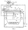
- Figure 1 is a view in elevation of a self-cleaning ink jet printer
belonging to the present invention, the printer including a page-width print head;
- Figure 2 is a fragmentation view in vertical section of the print
head, the print head defining a plurality of channels therein, each channel
terminating in an orifice;
- Figure 3 is a fragmentation view in vertical section of the print
head, this view showing some of the orifices encrusted with contaminant to be
removed;
- Figure 4 is a view in elevation of a cleaning assembly for removing
the contaminant;
- Figure 5 is a view in vertical section of the cleaning assembly, the
cleaning assembly including a septum disposed opposite the orifice so as to define
a gap between the orifice and the septum, this view also showing a cleaning liquid
flowing in a forward direction and an ultrasonic transducer for inducing pressure
waves in the liquid;
- Figure 6 is a view in vertical section of the cleaning assembly, the
cleaning assembly including a septum disposed opposite the orifice so as to define
a gap between the orifice and the septum, this view also showing a cleaning liquid
flowing in a reverse direction and the ultrasonic transducer for inducing pressure
waves in the liquid;
- Figure 7 is an enlarged fragmentation view in vertical section of the
cleaning assembly, this view also showing the contaminant being removed from
the surface and orifice by a liquid flowing alternately in forward and reverse
directions through the gap as the ultrasonic transducer induces pressure waves in
the liquid;
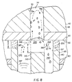
- Figure 8 is an enlarged fragmentation view in vertical section of the
cleaning assembly, this view showing the gap having reduced height due to
increased length of the septum, for cleaning contaminant from within the ink
channel;
- Figure 9 is an enlarged fragmentation view in vertical section of the
cleaning assembly, this view showing the gap having increased width due to
increased width of the septum, for cleaning contaminant from within the ink
channel;
- Figure 10 is a view in vertical section of a second embodiment of
the invention, wherein the cleaning assembly includes a pressurized gas supply in
fluid communication with the gap for introducing gas bubbles into the liquid in the
gap, this view also showing the liquid flowing in the forward direction as the
ultrasonic transducer induces pressure waves in the liquid;
- Figure 11 is a view in vertical section of the second embodiment of
the invention, wherein the cleaning assembly includes a pressurized gas supply in
fluid communication with the gap for introducing gas bubbles into the liquid in the
gap, this view showing the liquid flowing in the reverse direction as the ultrasonic
transducer induces pressure waves in the liquid;
- Figure 12 is a view in vertical section of a third embodiment of the
invention, wherein the septum is absent for increasing size of the gap to its
maximum extent, this view also showing the liquid flowing in the forward
direction as the ultrasonic transducer induces pressure waves in the liquid;
- Figure 13 is a view in vertical section of the third embodiment of
the invention, wherein the septum is absent for increasing size of the gap to its
maximum extent, this view showing the liquid flowing in the reverse direction as
the ultrasonic transducer induces pressure waves in the liquid; and
- Figure 14 is a view in vertical section of a fourth embodiment of
the invention, wherein the septum is absent and flow of cleaning liquid is directed
into the channel through the orifice while the liquid flows in the forward direction
and while the ultrasonic transducer induces pressure waves in the liquid.
-
DETAILED DESCRIPTION OF THE INVENTION
-
The present description will be directed in particular to elements
forming part of, or cooperating more directly with, apparatus in accordance with
the present invention. It is to be understood that elements not specifically shown
or described may take various forms well known to those skilled in the art.
-
Therefore, referring to Fig. 1, there is shown a self-cleaning printer,
generally referred to as 10, for printing an image 20 on a receiver 30, which may
be a reflective-type receiver (e.g., paper) or a transmissive-type receiver (e.g.,
transparency). Receiver 30 is supported on a platen roller 40 which is capable of
being rotated by a platen roller motor 50 engaging platen roller 40. Thus, when
platen roller motor 50 rotates platen roller 40, receiver 30 will advance in a
direction illustrated by a first arrow 55.
-
Referring to Figs. 1 and 2, printer 10 also comprises a "page-width"
print head 60 disposed adjacent to platen roller 40. Print head 60 comprises a
print head body 65 having a plurality of ink channels 70, each channel 70
terminating in a channel outlet 75. In addition, each channel 70, which is adapted
to hold an ink body 77 therein, is defined by a pair of oppositely disposed parallel
side walls 79a and 79b. Attached, such as by a suitable adhesive, to print head
body 65 is a cover plate 80 having a plurality of orifices 85 formed therethrough
colinearly aligned with respective ones of channel outlets 75. A surface 90 of
cover plate 80 surrounds all orifices 85 and faces receiver 20. Of course, in order
to print image 20 on receiver 30, an ink droplet 100 must be released from orifice
85 in direction of receiver 20, so that droplet 100 is intercepted by receiver 20. To
achieve this result, print head body 65 may be a "piezoelectric ink jet" print head
body formed of a piezoelectric material, such as lead zirconium titanate (PZT).
Such a piezoelectric material is mechanically responsive to electrical stimuli so
that side walls 79a/b simultaneously inwardly deform when electrically stimulated.
When side walls 79a/b simultaneously inwardly deform, volume of channel 70
decreases to squeeze ink droplet 100 from channel 70. Ink droplet 100 is
preferably ejected along a first axis 107 normal to orifice 85. Of course, ink is
supplied to channels 70 from an ink supply container 109. Also, supply container
109 is preferably pressurized such that ink pressure delivered to print head 60 is
controlled by an ink pressure regulator 110.
-
Still referring to Figs. 1 and 2, receiver 30 is moved relative to
page-width print head 60 by rotation of platen roller 40, which is electronically
controlled by paper transport control system 120. Paper transport control system
120 is in turn controlled by controller 130. Paper transport control system 120
disclosed herein is by way of example only, and many different configurations are
possible based on the teachings herein. In the case of page-width print head 60, it
is more convenient to move receiver 30 past stationary head 60. Controller 130,
which is connected to platen roller motor 50, ink pressure regulator 110 and a
cleaning assembly, enables the printing and print head cleaning operations.
Structure and operation of the cleaning assembly is described in detail
hereinbelow. Controller 130 may be a model CompuMotor controller available
from Parker Hannifin in Rohrnert Park, California U.S.A.
-
Turning now to Fig. 3, it has been observed that cover plate 80 may
become fouled by contaminant 140. Contaminant 140 may be, for example, an
oily film or particulate matter residing on surface 90. Contaminant 140 also may
partially or completely obstruct orifice 85. The particulate matter may be, for
example, particles of dirt, dust, metal and/or encrustations of dried ink. The oily
film may be, for example, grease or the like. Presence of contaminant 140 is
undesirable because when contaminant 140 completely obstructs orifice 85, ink
droplet 100 is prevented from being ejected from orifice 85. Also, when
contaminant 140 partially obstructs orifice 85, flight of ink droplet 100 may be
diverted from first axis 107 to travel along a second axis 145 (as shown). If ink
droplet 100 travels along second axis 145, ink droplet 100 will land on receiver 30
in an unintended location. In this manner, such complete or partial obstruction of
orifice 85 leads to printing artifacts such as "banding", a highly undesirable result.
Also, presence of contaminant 140 may alter surface wetting and inhibit proper
formation of droplet 100. Therefore, it is desirable to clean (i.e., remove)
contaminant 140 to avoid printing artifacts.
-
Therefore, referring to Figs. 1, 4, 5, 6 and 7, a cleaning assembly,
generally referred to as 170, is disposed proximate surface 90 for directing a flow
of cleaning liquid along surface 90 and across orifice 85 to clean contaminant 140
therefrom. Cleaning assembly 170 is movable from a first or "rest" position 172a
spaced-apart from surface 90 to a second position 172b engaging surface 90. This
movement is accomplished by means of an elevator 175 coupled to controller 130.
Cleaning assembly 170 may comprise a housing 180 for reasons described
presently. Disposed in housing 180 is a generally rectangular cup 190 having an
open end 195. Cup 190 defines a cavity 197 communicating with open end 195.
Attached, such as by a suitable adhesive, to open end 195 is an elastomeric seal
200, which may be rubber or the like, sized to encircle one or more orifices 85
and sealingly engage surface 90. Extending along cavity 197 and oriented
perpendicularly opposite orifices 85 is a structural member, such as an elongate
septum 210. Septum 210 has an end portion 215 which, when disposed opposite
orifice 85, defines a gap 220 of predetermined size between orifice 85 and end
portion 215. Moreover, end portion 215 of septum 210 may be disposed opposite
a portion of surface 90, not including orifice 85, so that gap 220 is defined
between surface 90 and end portion 215. As described in more detail
hereinbelow, gap 220 is sized to allow flow of a liquid therethrough in order to
clean contaminant 140 from surface 90 and/or orifice 85. By way of example
only, and not by way of limitation, the velocity of the liquid flowing through gap
220 may be about 1 to 20 meters per second. Also by way of example only, and
not by way of limitation, height of gap 220 may be approximately 3 to 30
thousandths of an inch. Moreover, hydrodynamic pressure applied to contaminant
140 in gap 220 due, at least in part, to presence of septum 210 may be
approximately 1 to 30 psi (pounds per square inch). Septum 210 partitions (i.e.,
divides) cavity 197 into an first chamber 230 and a second chamber 240, for
reasons described more fully hereinbelow. An ultrasonic transducer 245 capable
of generating a plurality of pressure pulse waves 247 is also provided for
enhancing cleaning effectiveness, as described in detail hereinbelow.
-
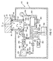
Referring again to Figs. 1, 4, 5 and 6, interconnecting first chamber
230 and second chamber 240 is a closed-loop piping circuit 250. It will be
appreciated that piping circuit 250 is in fluid communication with gap 220 for
recycling the liquid through gap 220. In this regard, piping circuit 250 comprises
a first piping segment 260 extending from second chamber 240 to a reservoir 270
containing a supply of the liquid. Piping circuit 250 further comprises a second
piping segment 280 extending from reservoir 270 to first chamber 230. Disposed
in second piping segment 280 is a recirculation pump 290. During a "forward
flow" mode of operation, pump 290 pumps the liquid from reservoir 270, through
second piping segment 280, into first chamber 230, through gap 220, into second
chamber 240, through first piping segment 260 and back to reservoir 270, as
illustrated by a plurality of second arrows 295. Disposed in first piping segment
260 may be a first filter 300 and disposed in second piping segment 280 may be a
second filter 310 for filtering (i.e., separating) contaminant 140 from the liquid as
the liquid circulates through piping circuit 250. It will be appreciated that portions
of the piping circuit 250 adjacent to cup 190 are preferably made of flexible tubing
in order to facilitate uninhibited translation of cup 190 toward and away from print
head 60, which translation is accomplished by means of elevator 175.
-
As best seen in Figs. 1 and 5, during forward fluid flow, a first
valve 320 is preferably disposed at a predetermined location in first piping
segment 260, which first valve 320 is operable to block flow of the liquid through
first piping segment 260. Also, a second valve 330 is preferably disposed at a
predetermined location in second piping segment 280, which second valve 330 is
operable to block flow of the liquid through second piping segment 280. In this
regard, first valve 320 and second valve 330 are located in first piping segment
260 and second piping segment 280, respectively, so as to isolate cavity 197 from
reservoir 270, for reasons described momentarily. A third piping segment 340 has
an open end thereof connected to first piping segment 260 and another open end
thereof received into a sump 350. In communication with sump 350 is a suction
(i.e., vacuum) pump 360 for reasons described presently. Suction pump 360
drains cup 190 and associated piping of cleaning liquid before cup is detached and
returned to first position 172a. Moreover, disposed in third piping segment 340 is
a third valve 370 operable to isolate piping circuit 250 from sump 350.
-
Referring to Figs. 5 and 6, the present invention also allows
reversed flow as well as forward flow of cleaning liquid through cup 190 and gap
220. In this regard, a junction, such as a 4-way valve (e.g., spool valve) 380, is
disposed into the piping circuit 260. When the 4-way valve 380 is in a first
position (shown in Fig. 5), cleaning liquid flows in a first direction (i.e., forward
direction) as illustrated by arrows 295. Thus, 4-way valve 380 may be viewed as a
valve system. When 4-way valve 380 is in a second position (shown in Fig. 6),
cleaning liquid flows in a second direction (i.e., reverse direction) as illustrated by
third arrows 385. Controller 130 may be used to operate 4-way valve 380 in
appropriate fashion and also to open an air bleed valve 382 during reverse flow.
Forward and reverse flow of cleaning liquid through gap 220 enhances cleaning
efficiency. Flow may be reversed a plurality of times depending on amount of
cleaning desired. The forward and reverse flow modes of operation described
herein may be applied to a so-called "scanning" print head or to the page-width
print head 60 described herein. Other methods of accomplishing reversed flow
can be used by one skilled in the art based on the teachings herein.
-
Referring to Figs. 5, 6 and 7, during "forward flow" operation of
cleaning assembly 170, first valve 320 and second valve 310 are opened while
third valve 370 is closed. Also, 4-way valve 380 is operated to its first position.
Recirculation pump 290 is then operated to draw the liquid from reservoir 270 and
into first chamber 230. The liquid will then flow through gap 220. However, as
the liquid flows through gap 220, a hydrodynamic shearing force will be induced
in the liquid due to presence of end portion 215 of septum 210. It is believed this
shearing force is in turn caused by a hydrodynamic stress forming in the liquid,
which stress has a "normal" component δn acting normal to surface 90 (or orifice
85) and a "shear" component τ acting along surface 90 (or across orifice 85).
Vectors representing the normal stress component δn and the shear stress
component τ are best seen in Fig. 7. The previously mentioned hydrodynamic
shearing force acts on contaminant 140 to remove contaminant 140 from surface
90 and/or orifice 85, so that contaminant 140 becomes entrained in the liquid
flowing through gap 220. As contaminant 140 is cleaned from surface 90 and
orifice 85, the liquid with contaminant 140 entrained therein, flows into second
chamber 240 and from there into first piping segment 260. As recirculation pump
290 continues to operate, the liquid with entrained contaminant 140 flows to
reservoir 270 from where the liquid is pumped into second piping segment 280.
However, it is preferable to remove contaminant 140 from the liquid as the liquid
is recirculated through piping circuit 250. This is preferred in order that
contaminant 140 is not redeposited onto surface 90 and across orifice 85. Thus,
first filter 300 and second filter 310 are provided for filtering contaminant 140
from the liquid recirculating through piping circuit 250. In this manner, 4-way
valve 380 is operated to permit forward fluid flow for a predetermined time
period. After the predetermined time for forward fluid flow, 4-way valve 380 is
then operated in its second position so that fluid flow is in the direction of third
arrows 385. After a desired amount of contaminant 140 is cleaned from surface
90 and/or orifice 85, recirculation pump 290 is caused to cease operation and first
valve 320 and second valve 330 are closed to isolate cavity 197 from reservoir
270. At this point, third valve 370 is opened and suction pump 360 is operated to
substantially suction the liquid from first piping segment 260, second piping
segment 280 and cavity 197. This suctioned liquid flows into sump 350 for later
disposal. However, the liquid flowing into sump 350 is substantially free of
contaminant 140 due to presence of filters 300/310 and thus may be recycled into
reservoir 270, if desired.
-
Referring to Figs. 8 and 9, it has been discovered that length and
width of elongate septum 210 controls amount of hydrodynamic stress acting
against surface 90 and orifice 85. This effect is important in order to control
severity of cleaning action. Also, it has been discovered that, when end portion
215 of septum 210 is disposed opposite orifice 85, length and width of elongate
septum 210 controls amount of penetration (as shown) of the liquid into channel
70. It is believed that control of penetration of the liquid into channel 70 is in turn
a function of the amount of normal stress δn. However, it has been discovered that
the amount of normal stress δn is inversely proportional to height of gap 220.
Therefore, normal stress δn, and thus amount of penetration of the liquid into
channel 70, can be increased by increasing length of septum 210. Moreover, it has
been discovered that amount of normal stress δn is directly proportional to
pressure drop in the liquid as the liquid slides along end portion 215 and surface
90. Therefore, normal stress δn, and thus amount of penetration of the liquid into
channel 70, can be increased by increasing width of septum 210. These effects are
important in order to clean any contaminant 140 which may be adhering to either
of side walls 79a or 79b. More specifically, when elongate septum 210 is
fabricated so that it has a greater than nominal length X, height of gap 220 is
decreased to enhance the cleaning action, if desired. Also, when elongate septum
210 is fabricated so that it has a greater than nominal width W, the run of gap 220
is increased to enhance the cleaning action, if desired. Thus, a person of ordinary
skill in the art may, without undue experimentation, vary both the length X and
width W of septum 210 to obtain an optimum gap size for obtaining optimum
cleaning depending on the amount and severity of contaminant encrustation. It
may be appreciated from the discussion hereinabove, that a height H of seal 200
also may be varied to vary size of gap 220 with similar results.
-
Returning to Fig. 1, elevator 175 may be connected to cleaning cup
190 for elevating cup 190 so that seal 200 sealingly engages surface 90 when print
head 60 is at second position 172b. To accomplish this result, elevator 175 is
connected to controller 130, so that operation of elevator 175 is controlled by
controller 130. Of course, when the cleaning operation is completed, elevator 175
may be lowered so that seal 200 no longer engages surface 90.
-
As best seen in Fig. 1, in order to clean the page-width print head
60 using cleaning assembly 170, platen roller 40 has to be moved to make room
for cup 190 to engage print head 60. An electronic signal from controller 130
activates a motorized mechanism (not shown) that moves platen roller 40 in
direction of first double-ended arrow 387 thus making room for upward
movement of cup 190. Controller 130 also controls elevator 175 for transporting
cup 190 from first position 172a not engaging print head 60 to second position
172b (shown in phantom) engaging print head 60. When cup 190 engages print
head cover plate 80, cleaning assembly 170 circulates liquid through cleaning cup
190 and over print head cover plate 80. When print head 60 is required for
printing, cup 190 is retracted into housing 180 by elevator 175 to its resting first
position 172a. The cup 190 may be advanced outwardly from and retracted
inwardly into housing 180 in direction of second double-ended arrow 388.
-
The mechanical arrangement described above is but one example.
Many different configurations are possible. For example, print head 60 may be
rotated outwardly about a horizontal axis 389 to a convenient position to provide
clearance for cup 190 to engage print head cover plate 80.
-
Referring to Figs. 5, 6, 7, 8 and 9, in communication with the liquid
in cavity 197 is a pressure pulse generator, such as the previously mentioned
ultrasonic generator 245, capable of generating a plurality of the pressure waves
247 (i.e., ultrasonic vibrations) in the liquid. Pressure waves 247 impact
contaminant 140 to dislodge contaminant 140 from surface 90 and/or orifice 85. It
is believed pressure waves 247 accomplish this result by adding kinetic energy to
the liquid along a vector directed substanially normal to surface 90 and orifices 85.
Of course, the liquid is substantially incompressible; therefore, pressure waves
247 propagate in the liquid in order to reach contaminate 140. By way of example
only, and not by way of limitation, pressure waves 247 may have a frequency of
aproximately 17,000 KHz and above.
-
Referring to Figs. 10 and 11, there is shown a second embodiment
of the present invention. In this second embodiment of the invention, a
pressurized gas supply 390 is in communication with gap 220 for injecting a
pressurized gas into gap 220. The gas will form a multiplicity of gas bubbles 395
in the liquid to enhance cleaning of contaminant 140 from surface 90 and/or
orifice 85.
-
Referring to Figs. 12 and 13, there is shown a third embodiment of
the present invention. In this third embodiment of the invention, septum 210 is
absent and contaminant 140 is cleaned from surface 90 and/or orifice 85 without
need of septum 210. In this case, gap 220 is sized to its maximum extent, due to
absence of septum 210, to allow a minimum amount of shear force to act against
contaminant 140. This embodiment of the invention is particularly useful when
there is a minimum amount of contaminant present or when it is desired to exert a
minimum amount of shear force against surface 90 and/or orifice 85 to avoid
possible damage to surface 90 and/or orifice 85.
-
Referring to Fig. 14, there is shown a fourth embodiment of the
present invention operating in "forward flow" mode. Although this fourth
embodiment is shown operating in "forward flow" mode, it may be appreciated
that this fourth embodiment can operate in "reverse flow" mode, as well. In this
fourth embodiment of the invention, septum 210 is absent and contaminant 140 is
cleaned from side walls 79a/b of channel 70 without need of septum 210. In this
case, piping circuit 250 comprises a flexible fourth piping segment 415 (e.g., a
flexible hose) interconnecting channel 70 and first piping segment 260. In this
regard, fourth piping segment 415 is sufficiently long and flexible to allow
unimpeded motion of print head 60 during printing. According to this fourth
embodiment of the invention, piping circuit 250 includes a fourth valve 417
disposed in first piping segment 260 and a fifth valve 420 is in communication
with channel 70. In addition, a sixth valve 430 is disposed in fourth piping
segment 415 between fifth valve 420 and first piping segment 260. During
operation, fourth valve 417, third valve 330 and fifth valve 420 are closed while
sixth valve 430 and second valve 330 are opened. Recirculation pump 290 is then
operated to pump the cleaning liquid into cavity 197. The cleaning liquid is
therefore circulated in the manner shown by the plurality of second arrows 295.
The liquid exiting through sixth valve 430 is transported through fourth piping
segment 415.
-
Still referring to Fig. 14, the liquid emerging through sixth valve
430 initially will be contaminated with contaminant 140. It is desirable to collect
this liquid in sump 350 rather than to recirculate the liquid. Therefore, this
contaminated liquid is directed to sump 350 by closing second valve 330 and
opening third valve 370 while suction pump 360 operates. The liquid will then be
free of contaminant 140 and may be recirculated by closing third valve 370 and
opening second valve 330. A detector 440 is disposed in first piping segment 260
to determine when the liquid is clean enough to be recirculated. Information from
detector 440 can be processed and used to activate the valves in order to direct
exiting liquid either into sump 350 or into recirculation. In this regard, detector
440 may be a spectrophotometric detector. In any event, at the end of the cleaning
procedure, suction pump 360 is activated and third valve 370 is opened to suction
into sump 350 any trapped liquid remaining between second valve 330 and first
valve 320. This process prevents spillage of liquid when cleaning assembly 170 is
detached from cover plate 80. Further, this process causes cover plate 80 to be
substantially dry, thereby permitting print head 60 to function without impedance
from cleaning liquid drops being around orifices 85. To resume printing, sixth
valve 430 is closed and fifth valve 420 is opened to prime channel 70 with ink.
Suction pump 360 is again activated, and third valve 370 is opened to suction any
liquid remaining in cup 190. Alternatively, the cup 190 may be detached and a
separate spittoon (not shown) may be brought into alignment with print head 60 to
collect drops of ink that are ejected from channel 70 during priming of print head
60.
-
The cleaning liquid may be any suitable liquid solvent composition,
such as water, isopropanol, diethylene glycol, diethylene glycol monobutyl ether,
octane, acids and bases, surfactant solutions and any combination thereof.
Complex liquid compositions may also be used, such as microemulsions, micellar
surfactant solutions, vesicles and solid particles dispersed in the liquid.
-
It may be appreciated from the description hereinabove, that an
advantage of the present invention is tat the cleaning assembly belonging to the
invention directly and effectively cleans print head surface 90, ink droplet orifices
85 and ink channels 70. This is so because septum 210 induces shear stress in the
liquid tat flows through gap 220 to clean contaminant 140 from surface 90 and/or
orifice 85 and also ink channels 70. This is also true because operation of 4-way
valve 380 induces to-and-fro motion of the cleaning fluid in the gap, thereby
agitating the liquid coming into contact with contaminant 140. Agitation of the
liquid in this manner in turn agitates contaminant 140 in order to loosen
contaminant 140. This is so whether contaminant 140 is on surface 90, partially or
completely covering orifice 85 or located in ink channels 70. Also, use of
ultrasonic transducer 245 further enhances cleaning effectiveness due to action of
pressure waves 247 that are induced in the liquid by ultrasonic transduer 245.
-
While the invention has been described with particular reference to
its preferred embodiments, it will be understood by those skilled in the art that
various changes may be made and equivalents may be substituted for elements of
the preferred embodiments without departing from the invention. In addition,
many modifications may be made to adapt a particular situation and material to a
teaching of the present invention without departing from the essential teachings of
the invention. For example, a heater may be disposed in reservoir 270 to heat the
liquid therein for enhancing cleaning of surface 90, channel 70 and/or orifice 85.
This is particularly useful when the cleaning liquid is of a type that increases in
cleaning effectiveness as temperature of the liquid is increased. As another
example, in the case of a multiple color printer having a plurality of print heads
corresponding to respective ones of a plurality of colors, one or more dedicated
cleaning assemblies per color might be used to avoid cross-contamination of print
heads by inks of different colors. As yet another example, a contamination sensor
may be connected to cleaning assembly 170 for detecting when cleaning is needed.
In this regard, such a contamination sensor may a pressure transducer in fluid
communication with ink in channels 70 for detecting rise in ink back pressure
when partially or completely blocked channels 70 attempt to eject ink droplets
100. Such a contamination sensor may also be a flow detector in communication
with ink in channels 70 to detect low ink flow when partially or completely
blocked channels 70 attempt to eject ink droplets 100. Such a contamination
sensor may also be an optical detector in optical communication with surface 90
and orifices 85 to optically detect presence of contaminant 140 by means of
reflection or emissivity. Such a contamination sensor may further be a device
measuring amount of ink released into a spittoon-like container during
predetermined periodic purging of channels 70. In this case, the amount of ink
released into the spittoon-like container would be measured by the device and
compared against a known amount of ink that should be present in the spittoon-like
container if no orifices were blocked by contaminant 140.
-
Therefore, what is provided is a self-cleaning printer with reverse
fluid flow and ultrasonics and method of assembling the printer.