EP1006022B1 - Shaped foamable materials - Google Patents
Shaped foamable materials Download PDFInfo
- Publication number
- EP1006022B1 EP1006022B1 EP99309489A EP99309489A EP1006022B1 EP 1006022 B1 EP1006022 B1 EP 1006022B1 EP 99309489 A EP99309489 A EP 99309489A EP 99309489 A EP99309489 A EP 99309489A EP 1006022 B1 EP1006022 B1 EP 1006022B1
- Authority
- EP
- European Patent Office
- Prior art keywords
- foamable
- shaped
- structural member
- pieces
- hollow structural
- Prior art date
- Legal status (The legal status is an assumption and is not a legal conclusion. Google has not performed a legal analysis and makes no representation as to the accuracy of the status listed.)
- Expired - Lifetime
Links
- 239000000463 material Substances 0.000 title claims description 112
- 239000003973 paint Substances 0.000 claims description 18
- 239000006260 foam Substances 0.000 claims description 11
- 238000010438 heat treatment Methods 0.000 claims description 10
- 238000000034 method Methods 0.000 claims description 9
- 238000007598 dipping method Methods 0.000 claims 1
- 238000010276 construction Methods 0.000 description 7
- 230000003014 reinforcing effect Effects 0.000 description 7
- 238000003466 welding Methods 0.000 description 6
- 238000013016 damping Methods 0.000 description 3
- 238000001746 injection moulding Methods 0.000 description 3
- 239000002184 metal Substances 0.000 description 3
- 239000000203 mixture Substances 0.000 description 3
- 238000010422 painting Methods 0.000 description 3
- 230000000717 retained effect Effects 0.000 description 3
- 239000004156 Azodicarbonamide Substances 0.000 description 2
- 229910000831 Steel Inorganic materials 0.000 description 2
- 239000004840 adhesive resin Substances 0.000 description 2
- 229920006223 adhesive resin Polymers 0.000 description 2
- XOZUGNYVDXMRKW-AATRIKPKSA-N azodicarbonamide Chemical compound NC(=O)\N=N\C(N)=O XOZUGNYVDXMRKW-AATRIKPKSA-N 0.000 description 2
- 235000019399 azodicarbonamide Nutrition 0.000 description 2
- 150000001875 compounds Chemical class 0.000 description 2
- 238000005260 corrosion Methods 0.000 description 2
- 230000007797 corrosion Effects 0.000 description 2
- 229920006244 ethylene-ethyl acrylate Polymers 0.000 description 2
- 229920006225 ethylene-methyl acrylate Polymers 0.000 description 2
- 239000000835 fiber Substances 0.000 description 2
- 239000002657 fibrous material Substances 0.000 description 2
- 238000005187 foaming Methods 0.000 description 2
- 239000004088 foaming agent Substances 0.000 description 2
- 238000009413 insulation Methods 0.000 description 2
- 230000002093 peripheral effect Effects 0.000 description 2
- 239000010959 steel Substances 0.000 description 2
- CVOFKRWYWCSDMA-UHFFFAOYSA-N 2-chloro-n-(2,6-diethylphenyl)-n-(methoxymethyl)acetamide;2,6-dinitro-n,n-dipropyl-4-(trifluoromethyl)aniline Chemical compound CCC1=CC=CC(CC)=C1N(COC)C(=O)CCl.CCCN(CCC)C1=C([N+]([O-])=O)C=C(C(F)(F)F)C=C1[N+]([O-])=O CVOFKRWYWCSDMA-UHFFFAOYSA-N 0.000 description 1
- MWRWFPQBGSZWNV-UHFFFAOYSA-N Dinitrosopentamethylenetetramine Chemical compound C1N2CN(N=O)CN1CN(N=O)C2 MWRWFPQBGSZWNV-UHFFFAOYSA-N 0.000 description 1
- 239000012190 activator Substances 0.000 description 1
- 239000000654 additive Substances 0.000 description 1
- 239000000853 adhesive Substances 0.000 description 1
- 230000001070 adhesive effect Effects 0.000 description 1
- 125000003236 benzoyl group Chemical group [H]C1=C([H])C([H])=C(C([H])=C1[H])C(*)=O 0.000 description 1
- 229920001577 copolymer Polymers 0.000 description 1
- 239000005042 ethylene-ethyl acrylate Substances 0.000 description 1
- 239000006261 foam material Substances 0.000 description 1
- 239000003365 glass fiber Substances 0.000 description 1
- 229920005989 resin Polymers 0.000 description 1
- 239000011347 resin Substances 0.000 description 1
- 239000012260 resinous material Substances 0.000 description 1
- 229920003002 synthetic resin Polymers 0.000 description 1
- 239000000057 synthetic resin Substances 0.000 description 1
Images

Classifications
-
- B—PERFORMING OPERATIONS; TRANSPORTING
- B29—WORKING OF PLASTICS; WORKING OF SUBSTANCES IN A PLASTIC STATE IN GENERAL
- B29C—SHAPING OR JOINING OF PLASTICS; SHAPING OF MATERIAL IN A PLASTIC STATE, NOT OTHERWISE PROVIDED FOR; AFTER-TREATMENT OF THE SHAPED PRODUCTS, e.g. REPAIRING
- B29C44/00—Shaping by internal pressure generated in the material, e.g. swelling or foaming ; Producing porous or cellular expanded plastics articles
- B29C44/02—Shaping by internal pressure generated in the material, e.g. swelling or foaming ; Producing porous or cellular expanded plastics articles for articles of definite length, i.e. discrete articles
- B29C44/12—Incorporating or moulding on preformed parts, e.g. inserts or reinforcements
- B29C44/18—Filling preformed cavities
-
- B—PERFORMING OPERATIONS; TRANSPORTING
- B60—VEHICLES IN GENERAL
- B60R—VEHICLES, VEHICLE FITTINGS, OR VEHICLE PARTS, NOT OTHERWISE PROVIDED FOR
- B60R13/00—Elements for body-finishing, identifying, or decorating; Arrangements or adaptations for advertising purposes
- B60R13/08—Insulating elements, e.g. for sound insulation
-
- B—PERFORMING OPERATIONS; TRANSPORTING
- B62—LAND VEHICLES FOR TRAVELLING OTHERWISE THAN ON RAILS
- B62D—MOTOR VEHICLES; TRAILERS
- B62D29/00—Superstructures, understructures, or sub-units thereof, characterised by the material thereof
- B62D29/001—Superstructures, understructures, or sub-units thereof, characterised by the material thereof characterised by combining metal and synthetic material
- B62D29/002—Superstructures, understructures, or sub-units thereof, characterised by the material thereof characterised by combining metal and synthetic material a foamable synthetic material or metal being added in situ
Definitions
- the present invention relates to shaped foamable structures that can be used, for example, to fill a cavity of a hollow structural member and to reinforce the hollow structural member.
- the present invention also relates to shaped foamable materials and attaching devices that can be used to support the shaped foamable materials in a closed box-like hollow structural member constructed from a plurality of plates, such as rocker panels, pillars and roof side panels of a vehicle body. After being expanded, the foam material increases the damping and sound insulating powers of the hollow structural member and increases the strength and rigidity of the hollow structural member.
- Japanese Patent Laid-open Application Number 8-208871, and its corresponding US Patent No. 5,631,304 describes a foamable material for filling and reinforcing a hollow structure.
- a foamable material having block-like structure is taught and the block-like structure preferably has the same profile as the interior of the hollow structure.
- the block-like structure is placed against the interior of the hollow structure and heated in order to expand or foam the material, thereby filling and reinforcing the hollow structure.
- US-A-3,834,962 discloses a shaped foamable structure in accordance with the precharacterizing part of claim 1. It discloses a structure in which a foamable material is applied to non-foamable reinforcing strips, optionally in spaced individual areas thereof. An activator may be present.
- the time required to completely foam the shaped foamable material can be significantly reduced.
- One aspect of the present invention provides a shaped foamable structure for use in a hollow structural member, comprising a shaped foamable material comprising a plurality of interconnected foamable pieces and having clearances between adjacent foamable pieces for facilitating uniform heating of the shaped foamable material, characterised in that the foamable pieces are interconnected by foamable connecting pieces or foamable connecting means.
- Another aspect of the invention provides a method of forming a foam product within a hollow structural member using a foamable structure as above in comprising the steps of:
- One or more support members or attaching means may be provided to position the interconnected foamable pieces within the cavity of the hollow structural member.
- the interconnected foamable pieces do not contact the interior surface of the hollow structure. Instead, only the support members or attaching means contact the interior surface of the hollow structure. Therefore, the interior surface of the hollow structure can be painted after the foamable pieces are mounted inside the hollow structure, and before expanding the foamable pieces, because the foamable pieces do not block or cover the interior surface of the hollow structure.
- Such a shaped foamable material is particularly advantageous for a hollow structure having a relatively large cross-sectional area, because the shaped foamable material should have a correspondingly large cross-sectional area, so as to sufficiently fill the hollow structure cavity after expansion.
- the clearances provided within the present shaped foamable materials considerably reduce the time that it take to completely foam or expand the shaped foamable material compared to foamable materials having a block shape. For example, if a block-like foamable material is utilized for a hollow structure having a particularly large cross section, the center portion of the block like foamable material may not sufficiently foam or expand. Such problems can be overcome by the present shaped foamable materials.
- the interconnected foamable pieces of the shaped foamable material can be integrally formed by injection molding.
- This alternative provides an easy to use shaped foamable material, if the cavities of the hollow structures have uniform lengths.
- the interconnected foamable pieces can be separately formed. After forming the individual pieces, the foamable pieces can be interconnected by a variety of means for connecting the foamable pieces. Therefore, the length of the shaped foamable material can be easily changed, if necessary.
- the block shaped foamable material of US Patent No. 5,631,304 is mounted onto the surface of the hollow structure before expansion.
- the portions of the hollow structure interior can not be painted to protect the hollow structure interior from corrosion. That is, if the foamable material is mounted directly onto the interior surface of the hollow structure, the foamable material may block the paint from reaching the portions of the interior surface of the hollow structure.
- one or more mounting devices may preferably be used to provide a clearance between the foamable structure and the interior surface of the hollow structure.
- the hollow structure can be assembled with the foamable material mounted inside the hollow structure using at least one mounting device, such that the foamable material does not cover or block any interior surfaces of the hollow structure.
- the foamable material can be heated to expand and fill the hollow structure. In this case, the interior surface of the hollow structure has been painted to prevent corrosion.
- the foamable materials are preferably shaped for hollow structural members, such that the shaped foamable material is formed from a plurality of foamable pieces that are arranged with desired clearances and are interconnected with each other.
- an attaching means is utilized to position the shaped foamable material in a cavity of the hollow structural member.
- the shaped foamable material may preferably be disposed within the cavity of the hollow structural member in such a way that the foamable pieces of the shaped foamable material are arranged along the longitudinal direction of the hollow structural member.
- the shaped foamable material has a shape appropriate for a rocker panel of a vehicle body.
- the foamable pieces of the shaped foamable material may be integrally formed by injection molding.
- the respective foamable pieces of the shaped foamable material may be separately formed and then interconnected to provide an easy to use shaped foamable material.
- the foamable pieces may be interconnected with a connecting means, which for example may be a tenon and a corresponding mortice provided on the opposite surfaces of each of the foamable pieces, respectively.
- the tenon and mortise may have any of a variety of corresponding shapes.
- the shaped foamable structure may be disposed inside of a hollow structure and the shaped foamable structure and the hollow structure may be heated, thereby expanding the shaped foamable structure.
- a cross-linked, rigid foam structure is formed within the hollow structure, thereby providing sound dampening properties and reinforcing the hollow structure.
- Various compositions may be utilized to form the shaped foamable structure.
- means for expanding the shaped foamable structure, other than heating, may be utilized.
- one or more support pieces may be utilized to fix the shaped foamable structure inside the hollow structure, so that the shaped foamable structure does not contact the interior of the hollow structure.
- the hollow structure may optionally be dipped in a paint bath after the shaped foamable structure has been placed inside the hollow structure, but before the shaped foamable material is expanded.
- the term “foamable” is used to describe materials that can be expanded in size by means of an external energy source, such as heat.
- a “foamable” material is capable of expanding to form a foam like structure.
- the expansion ratio typically can be adjusted by adjusting the various compositions utilized to form the foamable material.
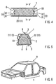
- FIGS. 1 to 6 A first representative embodiment of the invention is shown in FIGS. 1 to 6.
- a rocker panel 1 of a vehicle body A will be used as an example of a representative hollow structural member.
- the rocker panel 1 is constructed from an elongated inner panel 2 having flanges 3 extending along the peripheral edges of the elongated inner panel 2, and an elongated outer panel 4 having flanges 5 extending along the peripheral edges of the elongated inner panel 2.
- each of the inner panel 2 and the outer panel 4 is a two-piece construction having a pair of panel pieces. Such two-piece panels are used in order to increase the strength of the rocker panel.
- each of the panels 2 and 4 can be of a one-piece construction, if desired.
- the inner panel 2 and the outer panel 4 preferably are welded at flanges 3 and 5 by spot welding, so that the rocker panel 1 has an elongated, enclosed hollow structure and has a longitudinally extending cavity 6 inside the hollow structure.
- a shaped foamable structure 10 is preferably fixed within the cavity 6 of the rocker panel 1.
- This shaped foamable material 11 can be expanded to fill the cavity 6 and reinforce the rocker panel 1.
- the shaped foamable structure 10 is preferably constructed from a shaped foamable material 11 that is in an unfoamed state, and an attaching means or a pair of support members 30 for positioning the shaped foamable material 11 in the cavity 6.
- Each of the support members 30 can be a folded plate-like member that is formed of a steel plate and has a fixture base 31 and a support wall 32 that cross at right angles. Other designs for the support member naturally may be utilized.
- the support members 30 are preferably disposed in the cavity 6 of the rocker panel 1 at desired intervals in such a way that the support walls 32 are facing each other and are substantially perpendicular to the longitudinal direction of the cavity 6.
- the fixture bases 31 of the support member 30 can be secured to an inner surface of the rocker panel 1 by spot welding or other such fixing methods, so that the support members 30 are attached to the cavity 6.
- the support wall 32 of each support member 30 preferably has a non-circular opening 33 that is formed at the center of each support wall 32.
- the opening 33 may have a variety of shapes, although it preferably has a rectangular shape in this embodiment.
- the fixture bases 31 may be secured to the bottom surface of the outer panel 4 before the inner panel 2 and outer panel 4 are welded at flanges 3 and 5 in order to form the rocker panel 1.
- the inner panel 2 and the outer panel 4 provided with the support members 30 are joined to each other, thereby forming the hollow rocker panel 1 that receives the support members 30 in the cavity 6 of the hollow rocker panel 1.
- each support member 30 has an external dimension sufficiently smaller than the dimension of the transverse cross section of the cavity 6, so as to form a clearance between the periphery of the support member 30 and the inner surface of the rocker panel 1.
- This clearance is intended to permit paint to flow within the cavity 6 of the rocker panel 1 along the inner surface of the rocker panel 1, when the vehicle body A is dipped into a paint bath.
- the paint can be introduced into the cavity 6 through paint introduction holes (not shown) that may be formed in the rocker panel 1.
- the support members 30 are secured to the inner surface of the rocker panel 1 by spot welding, the support members 30 can be secured together using other securing means, such as screws, clips, magnets and adhesives, etc.
- the support members 30 can be made from heat-resistant synthetic resins or other such materials instead of a metal, such as steel.
- the shaped foamable material 11 can be a one piece element and can be supported by the pair of support members 30.
- the shaped foamable material 11 may preferably be constructed from a series of plate-like foamable pieces 12 that are arranged in parallel with desired clearances 13, a plurality of connecting pieces 14 that integrally interconnect the foamable pieces 12 at their central parts, and a pair of engagement projections 17 that are integrally provided on the foamable pieces 12 that are positioned at both ends of the series, respectively.
- these engagement projections 17 may project outward in an opposite relation and can engage the openings 33 of the support members 30.
- Each engagement projection 17 may preferably be adapted to tightly fit into the opening 33 that is formed in the support wall 32 of each support member 30.
- the engagement projection 17 may, for example, have a rectangular cross section that corresponds to the rectangular cross section of the opening 33. Therefore, the support members 30 can non-rotatably fix the shaped foamable material 11 when each engagement projection 17 is inserted into the opening 33 of the support member 30.
- each of the foamable pieces 12 in the unfoamed state preferably has an outer dimension that substantially conforms to the transverse cross-sectional configuration of the cavity 6.
- the external dimension may be slightly smaller than the dimension of the transverse cross section of the cavity 6, so that a clearance exists between the periphery of the foamable pieces 12 and the inner surface of the rocker panel 1. This clearance is intended to permit paint to flow in the cavity 6 of the rocker panel 1 along the inner surface of the rocker panel 1, when the vehicle body A is dipped into the paint bath.
- the shaped foamable material 11 i.e., the foamable pieces 12, the connecting pieces 14 and the engagement projections 17
- the foamable material is preferably made of a foamable material, such as foaming agents containing synthetic resinous materials, that can foam or expand at temperatures from about 110° C to about 190° C to provide a foamed product 20 (FIGS. 4 and 5).
- the foamable material preferably contains metal adhesive resins, fibrous materials and other additives, so as to produce a foamed product 20 that has high rigidity when it is expanded within the above-noted temperature range.
- the foaming agents may be azodicarbonamide (ADCA), oxy-bis(benzenecarbonyl hydrazide), dinitrosopentamethylenetetramine or other similar compounds.
- the metal adhesive resins may be an ethylene-methyl acrylate copolymer resin (EMA), an ethylene-ethyl acrylate copolymer (EEA), an etylene-butyl acrylate copolymer (EBA) or other similar compounds.
- the fibrous materials may be glass fibers, organic fibers or other fibers.
- the foamable material preferably is formulated so as to expand at an expansion ratio of about 2 to 5. Further examples of representative foamable material that can be used with the present teachings are disclosed in US Patent No. 5,631,304 and US Patent 6,403,668.
- the fixture base 31 of one of the support members 30 may be first secured to the bottom surface of the outer panel 4 by spot welding or other such methods in such a way that the support wall 32 is substantially perpendicular to the longitudinal direction of the outer panel 4.
- the inner panel 2 and outer panel 4 may then be welded at flanges 3 and 5 in order to form the rocker panel 1.
- one of the engagement projections 17 of the shaped foamable material 11 may be inserted into the opening 33 of the support wall 32 of the secured support member 30.
- Support member 30 may be positioned on the bottom surface of the outer panel 4 in such a way that its support wall 32 faces the support wall 32 that was previously secured to the outer panel 4.
- the second engagement projection 17 of the shaped foamable material 11 may be inserted into the opening 33 of the support wall 32 of this support member 30.
- the fixture base 31 of the second support member 30 can be secured to the bottom area of the outer panel 4 by spot welding or other such methods.
- the shaped foamable structure 10 is attached to the outer panel 4 in a manner that the foamable pieces 12 of the shaped foamable material 11 are preferably arranged in series along the longitudinal direction of the outer panel 4.
- the inner rocker panel 2 and the outer rocker panel 4 are welded at flanges 3 and 5 thereof by spot welding to form the rocker panel 1 having the shaped foamable structure 11 disposed in the cavity 6.
- the shaped foamable structure 10 is attached in the cavity 6 of the rocker panel 1 in such a way that the shaped foamable material 11 extends along the longitudinal direction of the cavity 6.
- the shaped foamable material 11 is preferably retained within the cavity 6 without contacting the inner surfaces of the panels 2 and 4, so as to form a clearance between the periphery of the shaped foamable material 11 and the inner surface of the rocker panel 1.
- the entire rocker panel 1 may optionally be introduced into the paint bath.
- the paint coats the outer surface of the rocker panel 1.
- the paint also enters the cavity 6 through paint introduction holes (not shown) that may be formed in the rocker panel 1.
- the paint also coats the cavity surfaces of the rocker panel 1.
- the paint introduced into the cavity 6 will be effectively applied to the inner surfaces of the rocker panel 1, because the shaped foamable material 11 is retained without contacting the inner surfaces of the rocker panel 1.
- the paint may suitably coat the cavity surfaces of the rocker panel 1 without leaving any un-painted portions.
- the rocker panel 1 can be heated using any suitable external heating source to both bake the paint coat and heat the shaped foamable material 11 within the cavity 6.
- the heated shaped foamable material 11 i.e., the foamable pieces 12, the connecting pieces 14 and the engagement projections 17
- the foamed products 20 thus produced reliably adhere to the entire interior surface of the rocker panel cavity 6.
- the foamed product 20 fills or closes the cavity 6, thereby providing excellent damping and sound insulation powers, as well as rigidity, to the rocker panel 1.
- the shaped foamable material 11 when the shaped foamable material 11 is heated by the external heat source, the heat can be effectively conducted to the shaped foamable material 11, due to the clearances 13 provided between the foamable pieces 12. As a result, the shaped foamable material 11 can be quickly and uniformly heated, so as to foam at a desired expansion ratio in a short amount of time. Therefore, such a shaped foamable structure 10 may be specifically useful, if the rocker panel 1 has a large cross-sectional area.
- the support walls 32 of the support members 30 may effectively prevent the foamed product 20 from inappropriately expanding in the longitudinal direction of the cavity 6, because the shaped foamable material 11 is retained between the support members 30 that are arranged perpendicular to the longitudinal direction of the cavity 6. Therefore, the foamed product 20 desirably fills or closes the cavity 6 of the rocker panel 1 and reliably adheres to the entire cavity surface. This feature may further contribute to increasing damping and sound insulation powers and rigidity of the rocker panel 1.
- each of the foamable pieces 12, the connecting pieces 14 and the engagement projections 17 can be formed by injection molding the foamable material.
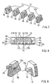
- FIGS. 7 and 8 A second representative embodiment, which is closely related to the first representative embodiment, is shown in FIGS. 7 and 8. Therefore, only constructions that are different from those constructions described in the first representative embodiment will be explained with respect to the second representative embodiment.
- the shaped foamable material 11 is substantially constructed from a plurality of foamable pieces 12 and one specially formed foamable piece 12a, which pieces are formed separately from each other.
- each of the foamable pieces 12 has a tenon 15 to serve as a connecting means, which tenon 15 is provided on at least one surface of each foamable piece 12.
- the tenon 15 preferably has a rectangular cross section and a desired length.
- each foamable piece 12 has a corresponding mortise 16 to serve as the connecting means, which mortise 16 is formed on the opposite surface from the tenon 15.
- the tenon 15 and mortise 16 are preferably formed to fit tightly together and the depth of the mortise 16 is preferably less than the length of the tenon 15.
- the special foamable piece 12a has tenons 15 provided on both surfaces. These tenons 15 preferably project in opposite directions and are aligned with each other.
- the normal foamable pieces 12 and the special foamable piece 12a may be arranged in series in such a way that the tenons 15 and the mortises 16 are adjacent to each other. Thereafter, the respective tenons 15 are press fitted into the respective mortises 16, thereby producing the shaped foamable material 11 in which the foamable pieces 12 and 12a are arranged in parallel with desired clearances 13.
- each tenon 15 of the terminal normal foamable piece 12 and the remaining tenon 15 of the special foamable piece 12a function as engagement projections that engage the openings 33 that is formed in the support wall 32 of each support member 30. Therefore, each tenon 15 is preferably formed to fit tightly inside each opening 33.
- the tenon 15 has a rectangular cross section and the mortise 16 has a corresponding rectangular shape so as to tightly fit with the tenon 15.
- the shapes of the tenon 15 and the mortise 16 are not limited to such a shape.
- the tenon 15 can be provided with a removed part 15a along the entire length thereof, and the mortise 16 can be provided with a corresponding removed part 16a extending therethrough.
- the tenon 15 and the mortise 16 can be designed so as to have a notched rectangular cross section.
- the adjacent foamable pieces 12 and 12a can be necessarily aligned in desired directions. As a result, the foamable pieces 12 and 12a can not be inadvertently coupled in the wrong position. Therefore, the shaped foamable material 11 can be easily and reliably manufactured.
- the shapes of the tenon 15 and the mortise 16 are also not limited to the notched rectangular cross section.
- the cross-sectional shape of the tenon 15 and the mortise 16 can be, for example, a trapezoidal shape, a triangular shape, a notched circular shape or other such shapes that can provide such a connecting function.
- the shaped foamable material 11 is positioned and supported in the cavity 6 of the rocker panel 1 by means of the pair of support members 30.
- the attaching means is not limited to such support members 30.
- the rocker panel 1 of a vehicle body has been utilized as a representative hollow structural member.
- the hollow structural member is not limited to the rocker panel and may be a pillar, a roof side panel or other panels of a vehicle body.
- the hollow structural member is not limited to parts of a vehicle body, as the present teachings are equally applicable to the filling and/or reinforcing of any hollow members, such as structural components for buildings and ships.
Description
- The present invention relates to shaped foamable structures that can be used, for example, to fill a cavity of a hollow structural member and to reinforce the hollow structural member. The present invention also relates to shaped foamable materials and attaching devices that can be used to support the shaped foamable materials in a closed box-like hollow structural member constructed from a plurality of plates, such as rocker panels, pillars and roof side panels of a vehicle body. After being expanded, the foam material increases the damping and sound insulating powers of the hollow structural member and increases the strength and rigidity of the hollow structural member.
- Japanese Patent Laid-open Application Number 8-208871, and its corresponding US Patent No. 5,631,304 describes a foamable material for filling and reinforcing a hollow structure. In particular, a foamable material having block-like structure is taught and the block-like structure preferably has the same profile as the interior of the hollow structure. The block-like structure is placed against the interior of the hollow structure and heated in order to expand or foam the material, thereby filling and reinforcing the hollow structure.
- US-A-3,834,962 discloses a shaped foamable structure in accordance with the precharacterizing part of
claim 1. It discloses a structure in which a foamable material is applied to non-foamable reinforcing strips, optionally in spaced individual areas thereof. An activator may be present. - It is an object of the present teachings to provide improved filling and reinforcing shaped foamable materials for hollow structures. Preferably, by modifying the exterior shape of the shaped foamable material, the time required to completely foam the shaped foamable material can be significantly reduced. In addition, it may be possible to improve the expansion properties of the shaped foamable materials.
- One aspect of the present invention provides a shaped foamable structure for use in a hollow structural member, comprising a shaped foamable material comprising a plurality of interconnected foamable pieces and having clearances between adjacent foamable pieces for facilitating uniform heating of the shaped foamable material, characterised in that the foamable pieces are interconnected by foamable connecting pieces or foamable connecting means.
- Another aspect of the invention provides a method of forming a foam product within a hollow structural member using a foamable structure as above in comprising the steps of:
- fixing the shaped foamable material inside the hollow structural member such that the exterior of the shaped foamable material does not contact the interior of the hollow structural member, and
- heating the shaped foamable material and the hollow structural member, whereby the shaped foamable material expands to fill and adhere to the interior surface of the hollow structural member.
-
- One or more support members or attaching means may be provided to position the interconnected foamable pieces within the cavity of the hollow structural member. The interconnected foamable pieces do not contact the interior surface of the hollow structure. Instead, only the support members or attaching means contact the interior surface of the hollow structure. Therefore, the interior surface of the hollow structure can be painted after the foamable pieces are mounted inside the hollow structure, and before expanding the foamable pieces, because the foamable pieces do not block or cover the interior surface of the hollow structure.
- With such interconnected foamable pieces, external heating for expanding the shaped foamable material can be effectively conducted throughout the entire shaped foamable material. That is, the clearances provided between the foamable pieces allow the entire shaped foamable material to be quickly and uniformly heated, thereby ensuring that the foam pieces expand at the desired ratio in a short amount of time.
- Such a shaped foamable material is particularly advantageous for a hollow structure having a relatively large cross-sectional area, because the shaped foamable material should have a correspondingly large cross-sectional area, so as to sufficiently fill the hollow structure cavity after expansion. The clearances provided within the present shaped foamable materials considerably reduce the time that it take to completely foam or expand the shaped foamable material compared to foamable materials having a block shape. For example, if a block-like foamable material is utilized for a hollow structure having a particularly large cross section, the center portion of the block like foamable material may not sufficiently foam or expand.
Such problems can be overcome by the present shaped foamable materials. - In one aspect, the interconnected foamable pieces of the shaped foamable material can be integrally formed by injection molding. This alternative provides an easy to use shaped foamable material, if the cavities of the hollow structures have uniform lengths. In the alternative, the interconnected foamable pieces can be separately formed. After forming the individual pieces, the foamable pieces can be interconnected by a variety of means for connecting the foamable pieces. Therefore, the length of the shaped foamable material can be easily changed, if necessary.
- In the course of further researching the foamable materials described in US Patent No. 5,631,304, it was discovered that the expansion or foaming properties of the foamable materials could be remarkably improved by modify the shape of the foamable materials. In particular, it was found that a fin like foamable structure can be quickly expanded using external heat. This fin like structure will expand into a uniform foamed structure that provides excellent sound proofing and reinforcing properties. Other types of structures that improve the uniform heating and foaming capabilities of the foamable materials are naturally contemplated by the present teachings.
- In addition, the block shaped foamable material of US Patent No. 5,631,304 is mounted onto the surface of the hollow structure before expansion. However, if the hollow structure has not been painted before the block shaped foamable material is placed inside the hollow structure, the portions of the hollow structure interior can not be painted to protect the hollow structure interior from corrosion. That is, if the foamable material is mounted directly onto the interior surface of the hollow structure, the foamable material may block the paint from reaching the portions of the interior surface of the hollow structure.
- Therefore, in order to provide an improved shaped foamable structure, one or more mounting devices may preferably be used to provide a clearance between the foamable structure and the interior surface of the hollow structure. Thus, the hollow structure can be assembled with the foamable material mounted inside the hollow structure using at least one mounting device, such that the foamable material does not cover or block any interior surfaces of the hollow structure. After painting the interior of the hollow structure, for example by dip painting, the foamable material can be heated to expand and fill the hollow structure. In this case, the interior surface of the hollow structure has been painted to prevent corrosion.
- As a result, the foamable materials are preferably shaped for hollow structural members, such that the shaped foamable material is formed from a plurality of foamable pieces that are arranged with desired clearances and are interconnected with each other. Preferably, an attaching means is utilized to position the shaped foamable material in a cavity of the hollow structural member. The shaped foamable material may preferably be disposed within the cavity of the hollow structural member in such a way that the foamable pieces of the shaped foamable material are arranged along the longitudinal direction of the hollow structural member. Most preferably, the shaped foamable material has a shape appropriate for a rocker panel of a vehicle body.
- The foamable pieces of the shaped foamable material may be integrally formed by injection molding. In the alternative, the respective foamable pieces of the shaped foamable material may be separately formed and then interconnected to provide an easy to use shaped foamable material. For example, the foamable pieces may be interconnected with a connecting means, which for example may be a tenon and a corresponding mortice provided on the opposite surfaces of each of the foamable pieces, respectively. The tenon and mortise may have any of a variety of corresponding shapes.
- In addition, methods of using foamable materials are taught. For example, the shaped foamable structure may be disposed inside of a hollow structure and the shaped foamable structure and the hollow structure may be heated, thereby expanding the shaped foamable structure. Preferably, a cross-linked, rigid foam structure is formed within the hollow structure, thereby providing sound dampening properties and reinforcing the hollow structure. Various compositions may be utilized to form the shaped foamable structure. Further, means for expanding the shaped foamable structure, other than heating, may be utilized. Additionally, one or more support pieces may be utilized to fix the shaped foamable structure inside the hollow structure, so that the shaped foamable structure does not contact the interior of the hollow structure. Moreover, the hollow structure may optionally be dipped in a paint bath after the shaped foamable structure has been placed inside the hollow structure, but before the shaped foamable material is expanded.
- For the purposes of this specification, the term "foamable" is used to describe materials that can be expanded in size by means of an external energy source, such as heat. Thus, a "foamable" material is capable of expanding to form a foam like structure. The expansion ratio typically can be adjusted by adjusting the various compositions utilized to form the foamable material.
- Each of the additional features and constructions disclosed above and below may be utilized separately or in conjunction with other features and constructions to provide improved shaped foamable materials and methods for making and using such shaped foamable materials. Detailed representative examples of the present invention, which examples utilize many of these additional features and constructions in conjunction, will now be described in detail with reference to the drawings. This detailed description is merely intended to teach a person of skill in the art further details for practicing preferred aspects of the present teachings and is not intended to limit the scope of the invention. Only the claims define the scope of the claimed invention. Therefore, combinations of features and steps disclosed in the following detail description may not be necessary to practice the invention in the broadest sense, and are instead taught merely to particularly describe some representative examples of the invention, which detailed description will now be given with reference to the accompanying drawings.
- The invention will be further described by way of example with reference to the accompanying drawings, in which:
- FIG. 1 is an exploded perspective view of a shaped foamable material for a rocker panel according to a first representative embodiment of the present teachings;
- FIG, 2 is a vertical sectional view of the shaped foamable material disposed in a cavity of the rocker panel before the shaped foamable material is expanded;
- FIG. 3 is a sectional view taken along the line III-III in FIG. 2;
- FIG. 4 is a vertical sectional view of the shaped foamable material disposed in the cavity of the rocker panel after the shaped foamable material is expanded;
- FIG. 5 is a sectional view taken along the line V-V in FIG. 4;
- FIG. 6 is a schematic view of a vehicle body showing the position of the rocker panel;
- FIG. 7 is a perspective view of a shaped foamable material of a shaped foamable material for a rocker panel according to a second representative embodiment of the present teachings;
- FIG. 8 is a vertical sectional view of the shaped foamable material disposed in a cavity of the rocker panel before the shaped foamable material is expanded; and
- FIG. 9 is a perspective view of a modified form of the shaped foamable material according to the second representative embodiment.
-
- A first representative embodiment of the invention is shown in FIGS. 1 to 6. As shown in FIG. 6, a
rocker panel 1 of a vehicle body A will be used as an example of a representative hollow structural member. As best shown in FIGS. 1 and 3, therocker panel 1 is constructed from an elongatedinner panel 2 havingflanges 3 extending along the peripheral edges of the elongatedinner panel 2, and an elongatedouter panel 4 havingflanges 5 extending along the peripheral edges of the elongatedinner panel 2. As will be readily appreciated, each of theinner panel 2 and theouter panel 4 is a two-piece construction having a pair of panel pieces. Such two-piece panels are used in order to increase the strength of the rocker panel. However, each of thepanels inner panel 2 and theouter panel 4 preferably are welded atflanges rocker panel 1 has an elongated, enclosed hollow structure and has a longitudinally extendingcavity 6 inside the hollow structure. - As best shown in FIGS. 1 to 3, a shaped
foamable structure 10 is preferably fixed within thecavity 6 of therocker panel 1. This shapedfoamable material 11 can be expanded to fill thecavity 6 and reinforce therocker panel 1. The shapedfoamable structure 10 is preferably constructed from a shapedfoamable material 11 that is in an unfoamed state, and an attaching means or a pair ofsupport members 30 for positioning the shapedfoamable material 11 in thecavity 6. Each of thesupport members 30 can be a folded plate-like member that is formed of a steel plate and has afixture base 31 and asupport wall 32 that cross at right angles. Other designs for the support member naturally may be utilized. - The
support members 30 are preferably disposed in thecavity 6 of therocker panel 1 at desired intervals in such a way that thesupport walls 32 are facing each other and are substantially perpendicular to the longitudinal direction of thecavity 6. The fixture bases 31 of thesupport member 30 can be secured to an inner surface of therocker panel 1 by spot welding or other such fixing methods, so that thesupport members 30 are attached to thecavity 6. As best shown in FIG. 1, thesupport wall 32 of eachsupport member 30 preferably has anon-circular opening 33 that is formed at the center of eachsupport wall 32. Theopening 33 may have a variety of shapes, although it preferably has a rectangular shape in this embodiment. - As will be readily appreciated, the fixture bases 31 may be secured to the bottom surface of the
outer panel 4 before theinner panel 2 andouter panel 4 are welded atflanges rocker panel 1. In other words, theinner panel 2 and theouter panel 4 provided with thesupport members 30 are joined to each other, thereby forming thehollow rocker panel 1 that receives thesupport members 30 in thecavity 6 of thehollow rocker panel 1. - As best shown in FIG. 3, the
support wall 32 of eachsupport member 30 has an external dimension sufficiently smaller than the dimension of the transverse cross section of thecavity 6, so as to form a clearance between the periphery of thesupport member 30 and the inner surface of therocker panel 1. This clearance is intended to permit paint to flow within thecavity 6 of therocker panel 1 along the inner surface of therocker panel 1, when the vehicle body A is dipped into a paint bath. As will be recognized, the paint can be introduced into thecavity 6 through paint introduction holes (not shown) that may be formed in therocker panel 1. - In this representative embodiment, although the pair of
support members 30 are secured to the inner surface of therocker panel 1 by spot welding, thesupport members 30 can be secured together using other securing means, such as screws, clips, magnets and adhesives, etc. In addition, thesupport members 30 can be made from heat-resistant synthetic resins or other such materials instead of a metal, such as steel. - Further, as shown in FIGS. 1 and 2, the shaped
foamable material 11 can be a one piece element and can be supported by the pair ofsupport members 30. The shapedfoamable material 11 may preferably be constructed from a series of plate-likefoamable pieces 12 that are arranged in parallel with desiredclearances 13, a plurality of connectingpieces 14 that integrally interconnect thefoamable pieces 12 at their central parts, and a pair ofengagement projections 17 that are integrally provided on thefoamable pieces 12 that are positioned at both ends of the series, respectively. As best shown in FIG. 2, theseengagement projections 17 may project outward in an opposite relation and can engage theopenings 33 of thesupport members 30. Eachengagement projection 17 may preferably be adapted to tightly fit into theopening 33 that is formed in thesupport wall 32 of eachsupport member 30. That is, theengagement projection 17 may, for example, have a rectangular cross section that corresponds to the rectangular cross section of theopening 33. Therefore, thesupport members 30 can non-rotatably fix the shapedfoamable material 11 when eachengagement projection 17 is inserted into theopening 33 of thesupport member 30. - Moreover, as best shown in FIG. 3, each of the
foamable pieces 12 in the unfoamed state preferably has an outer dimension that substantially conforms to the transverse cross-sectional configuration of thecavity 6. Further, the external dimension may be slightly smaller than the dimension of the transverse cross section of thecavity 6, so that a clearance exists between the periphery of thefoamable pieces 12 and the inner surface of therocker panel 1. This clearance is intended to permit paint to flow in thecavity 6 of therocker panel 1 along the inner surface of therocker panel 1, when the vehicle body A is dipped into the paint bath. - While various compositions can be utilized to form the shaped foamable material 11 (i.e., the
foamable pieces 12, the connectingpieces 14 and the engagement projections 17), it is preferably made of a foamable material, such as foaming agents containing synthetic resinous materials, that can foam or expand at temperatures from about 110° C to about 190° C to provide a foamed product 20 (FIGS. 4 and 5). In addition, the foamable material preferably contains metal adhesive resins, fibrous materials and other additives, so as to produce a foamedproduct 20 that has high rigidity when it is expanded within the above-noted temperature range. By way of example, the foaming agents may be azodicarbonamide (ADCA), oxy-bis(benzenecarbonyl hydrazide), dinitrosopentamethylenetetramine or other similar compounds. The metal adhesive resins may be an ethylene-methyl acrylate copolymer resin (EMA), an ethylene-ethyl acrylate copolymer (EEA), an etylene-butyl acrylate copolymer (EBA) or other similar compounds. The fibrous materials may be glass fibers, organic fibers or other fibers. Further, the foamable material preferably is formulated so as to expand at an expansion ratio of about 2 to 5. Further examples of representative foamable material that can be used with the present teachings are disclosed in US Patent No. 5,631,304 and US Patent 6,403,668. - A representative method for incorporating the shaped
foamable structure 10 into thecavity 6 of therocker panel 1 and subsequent operations will now be described. Specifically, thefixture base 31 of one of thesupport members 30 may be first secured to the bottom surface of theouter panel 4 by spot welding or other such methods in such a way that thesupport wall 32 is substantially perpendicular to the longitudinal direction of theouter panel 4. Theinner panel 2 andouter panel 4 may then be welded atflanges rocker panel 1. Subsequently, one of theengagement projections 17 of the shapedfoamable material 11 may be inserted into theopening 33 of thesupport wall 32 of thesecured support member 30.Support member 30 may be positioned on the bottom surface of theouter panel 4 in such a way that itssupport wall 32 faces thesupport wall 32 that was previously secured to theouter panel 4. At the same time, thesecond engagement projection 17 of the shapedfoamable material 11 may be inserted into theopening 33 of thesupport wall 32 of thissupport member 30. Under this condition, thefixture base 31 of thesecond support member 30 can be secured to the bottom area of theouter panel 4 by spot welding or other such methods. Thus, the shapedfoamable structure 10 is attached to theouter panel 4 in a manner that thefoamable pieces 12 of the shapedfoamable material 11 are preferably arranged in series along the longitudinal direction of theouter panel 4. - Subsequently, the
inner rocker panel 2 and theouter rocker panel 4 are welded atflanges rocker panel 1 having the shapedfoamable structure 11 disposed in thecavity 6. As a result, the shapedfoamable structure 10 is attached in thecavity 6 of therocker panel 1 in such a way that the shapedfoamable material 11 extends along the longitudinal direction of thecavity 6. As shown in FIGS. 2 and 3, the shapedfoamable material 11 is preferably retained within thecavity 6 without contacting the inner surfaces of thepanels foamable material 11 and the inner surface of therocker panel 1. - Thereafter, the
entire rocker panel 1 may optionally be introduced into the paint bath. During this dip painting operation, the paint coats the outer surface of therocker panel 1. The paint also enters thecavity 6 through paint introduction holes (not shown) that may be formed in therocker panel 1. Thus, the paint also coats the cavity surfaces of therocker panel 1. As will be easily understood, the paint introduced into thecavity 6 will be effectively applied to the inner surfaces of therocker panel 1, because the shapedfoamable material 11 is retained without contacting the inner surfaces of therocker panel 1. As a result, the paint may suitably coat the cavity surfaces of therocker panel 1 without leaving any un-painted portions. - The
rocker panel 1 can be heated using any suitable external heating source to both bake the paint coat and heat the shapedfoamable material 11 within thecavity 6. As a result, the heated shaped foamable material 11 (i.e., thefoamable pieces 12, the connectingpieces 14 and the engagement projections 17) will expand to produce the foamedproduct 20, as shown in FIGS. 4 and 5. The foamedproducts 20 thus produced reliably adhere to the entire interior surface of therocker panel cavity 6. As a result, the foamedproduct 20 fills or closes thecavity 6, thereby providing excellent damping and sound insulation powers, as well as rigidity, to therocker panel 1. - It is important to note that when the shaped
foamable material 11 is heated by the external heat source, the heat can be effectively conducted to the shapedfoamable material 11, due to theclearances 13 provided between thefoamable pieces 12. As a result, the shapedfoamable material 11 can be quickly and uniformly heated, so as to foam at a desired expansion ratio in a short amount of time. Therefore, such a shapedfoamable structure 10 may be specifically useful, if therocker panel 1 has a large cross-sectional area. - Also, as best shown in FIG. 4, when the shaped
foamable material 11 is expanded by heating, thesupport walls 32 of thesupport members 30 may effectively prevent the foamedproduct 20 from inappropriately expanding in the longitudinal direction of thecavity 6, because the shapedfoamable material 11 is retained between thesupport members 30 that are arranged perpendicular to the longitudinal direction of thecavity 6. Therefore, the foamedproduct 20 desirably fills or closes thecavity 6 of therocker panel 1 and reliably adheres to the entire cavity surface. This feature may further contribute to increasing damping and sound insulation powers and rigidity of therocker panel 1. - In this embodiment, each of the
foamable pieces 12, the connectingpieces 14 and theengagement projections 17 can be formed by injection molding the foamable material. - A second representative embodiment, which is closely related to the first representative embodiment, is shown in FIGS. 7 and 8. Therefore, only constructions that are different from those constructions described in the first representative embodiment will be explained with respect to the second representative embodiment.
- As shown in FIGS. 7 and 8, the shaped
foamable material 11 is substantially constructed from a plurality offoamable pieces 12 and one specially formedfoamable piece 12a, which pieces are formed separately from each other. Preferably, each of thefoamable pieces 12 has atenon 15 to serve as a connecting means, which tenon 15 is provided on at least one surface of eachfoamable piece 12. Thetenon 15 preferably has a rectangular cross section and a desired length. Moreover, eachfoamable piece 12 has acorresponding mortise 16 to serve as the connecting means, which mortise 16 is formed on the opposite surface from thetenon 15. Thetenon 15 andmortise 16 are preferably formed to fit tightly together and the depth of themortise 16 is preferably less than the length of thetenon 15. - On the other hand, unlike the
normal piece 12, the specialfoamable piece 12a hastenons 15 provided on both surfaces. Thesetenons 15 preferably project in opposite directions and are aligned with each other. - The normal
foamable pieces 12 and the specialfoamable piece 12a may be arranged in series in such a way that thetenons 15 and themortises 16 are adjacent to each other. Thereafter, therespective tenons 15 are press fitted into therespective mortises 16, thereby producing the shapedfoamable material 11 in which thefoamable pieces clearances 13. - As will be easily recognized, in the shaped
foamable material 11 thus constructed, thetenon 15 of the terminalnormal foamable piece 12 and the remainingtenon 15 of the specialfoamable piece 12a function as engagement projections that engage theopenings 33 that is formed in thesupport wall 32 of eachsupport member 30. Therefore, eachtenon 15 is preferably formed to fit tightly inside eachopening 33. - In this embodiment, the
tenon 15 has a rectangular cross section and themortise 16 has a corresponding rectangular shape so as to tightly fit with thetenon 15. However, the shapes of thetenon 15 and themortise 16 are not limited to such a shape. For example, as shown in FIG. 9, thetenon 15 can be provided with aremoved part 15a along the entire length thereof, and themortise 16 can be provided with a correspondingremoved part 16a extending therethrough. In other words, thetenon 15 and themortise 16 can be designed so as to have a notched rectangular cross section. As will be easily understood, in such a structure, the adjacentfoamable pieces foamable pieces foamable material 11 can be easily and reliably manufactured. - Further, it is important to note that the shapes of the
tenon 15 and themortise 16 are also not limited to the notched rectangular cross section. Instead, the cross-sectional shape of thetenon 15 and themortise 16 can be, for example, a trapezoidal shape, a triangular shape, a notched circular shape or other such shapes that can provide such a connecting function. - Moreover, in the first and the second representative embodiments, the shaped
foamable material 11 is positioned and supported in thecavity 6 of therocker panel 1 by means of the pair ofsupport members 30. However, the attaching means is not limited tosuch support members 30. - Further, the
rocker panel 1 of a vehicle body has been utilized as a representative hollow structural member. However, the hollow structural member is not limited to the rocker panel and may be a pillar, a roof side panel or other panels of a vehicle body. Moreover, the hollow structural member is not limited to parts of a vehicle body, as the present teachings are equally applicable to the filling and/or reinforcing of any hollow members, such as structural components for buildings and ships.
Claims (8)
- A shaped foamable structure (10) for use in a hollow structural member (1), comprising a shaped foamable material (11) comprising a plurality of interconnected foamable pieces (12) and having clearances (13) between adjacent foamable pieces (12) for facilitating uniform heating of the shaped foamable material, characterised in that the foamable pieces (12) are interconnected by foamable connecting pieces (14) or foamable connecting means (15, 16).
- A shaped foamable structure (10) according to claim 1, further comprising at least one support member (30) attached to the shaped foamable material (11) for positioning the shaped foamable material within a cavity (6) of the hollow structural member.
- A shaped foamable structure (10) as in claim 1 or 2, wherein the shaped foamable material (11) has a fin-like structure.
- A shaped foamable structure (10) as defined in claim 2 or 3, wherein the foamable connecting pieces (14) integrally connect the foamable pieces (12).
- A shaped foamable structure (10) as defined in claim 1, 2 or 3, wherein the foamable connecting means (15, 16) comprises a tenon (15) and a corresponding mortise (16) provided on opposite surfaces of each of the respectable foamable pieces (12) and wherein the foamable pieces (12) are interconnected by fitting the tenons (15) within the mortises (16).
- In combination a shaped foamable structure (10) according to any one of the preceding claims, and a hollow structural member (1), wherein the shaped foamable structure (10) is fixed within the hollow structural member (1), such that the exterior surface of the shaped foamable material (11) does not contact the interior surface of the hollow structural member (1) and the shaped foamable material (11) can be disposed in the interior of the hollow structural member (1) such that the foamable pieces (12) of the shaped foamable material are arranged along the longitudinal direction of the hollow structural member (1).
- The use of a shaped foamable structure according to any one of claims 1 to 5 in a method of forming a foam product (20) within a hollow structural member (1), comprising the steps of:fixing the shaped foamable structure inside the hollow structural member (1) such that the exterior of the shaped foamable material (11) does not contact the interior of the hollow structural member (1), andheating the shaped foamable material (11) and the hollow structural member (1), whereby the shaped foamable material (11) expands to fill and adhere to the interior surface of the hollow structural member (1).
- The use as in claim 7, wherein the method further comprises dipping the hollow structural member (1) and shaped foamable material (11) in a paint bath before the heating step, so as to coat the entire interior surface of the hollow structural member (1) with paint.
Applications Claiming Priority (2)
| Application Number | Priority Date | Filing Date | Title |
|---|---|---|---|
| JP34046398A JP3386730B2 (en) | 1998-11-30 | 1998-11-30 | Isolation and reinforcement tools for hollow structures |
| JP34046398 | 1998-11-30 |
Publications (3)
| Publication Number | Publication Date |
|---|---|
| EP1006022A2 EP1006022A2 (en) | 2000-06-07 |
| EP1006022A3 EP1006022A3 (en) | 2000-08-23 |
| EP1006022B1 true EP1006022B1 (en) | 2003-09-24 |
Family
ID=18337214
Family Applications (1)
| Application Number | Title | Priority Date | Filing Date |
|---|---|---|---|
| EP99309489A Expired - Lifetime EP1006022B1 (en) | 1998-11-30 | 1999-11-29 | Shaped foamable materials |
Country Status (4)
| Country | Link |
|---|---|
| US (1) | US6357819B1 (en) |
| EP (1) | EP1006022B1 (en) |
| JP (1) | JP3386730B2 (en) |
| DE (1) | DE69911553T2 (en) |
Cited By (6)
| Publication number | Priority date | Publication date | Assignee | Title |
|---|---|---|---|---|
| US6786533B2 (en) | 2001-09-24 | 2004-09-07 | L&L Products, Inc. | Structural reinforcement system having modular segmented characteristics |
| US6793274B2 (en) | 2001-11-14 | 2004-09-21 | L&L Products, Inc. | Automotive rail/frame energy management system |
| US6820923B1 (en) | 2000-08-03 | 2004-11-23 | L&L Products | Sound absorption system for automotive vehicles |
| US7784186B2 (en) | 2003-06-26 | 2010-08-31 | Zephyros, Inc. | Method of forming a fastenable member for sealing, baffling or reinforcing |
| US7790280B2 (en) | 2001-05-08 | 2010-09-07 | Zephyros, Inc. | Structural reinforcement |
| US8475694B2 (en) | 2005-10-25 | 2013-07-02 | Zephyros, Inc. | Shaped expandable material |
Families Citing this family (70)
| Publication number | Priority date | Publication date | Assignee | Title |
|---|---|---|---|---|
| CA2406701A1 (en) * | 2000-01-31 | 2001-08-02 | Sika Corporation | Structural reinforcing member with ribbed thermally expansible foaming material |
| AU2001230965A1 (en) * | 2000-02-11 | 2001-08-20 | L And L Products, Inc. | Structural reinforcement system for automotive vehicles |
| JP2002166804A (en) * | 2000-12-01 | 2002-06-11 | Kojima Press Co Ltd | Vehicular impact absorbing structure body and impact absorbing structure of vehicular interior parts using the same |
| DE10112688A1 (en) * | 2001-03-16 | 2002-09-26 | Sika Ag, Vormals Kaspar Winkler & Co | Reinforcement for vehicle bodywork pillars, and other hollow components, is a strengthening skeleton of injection molded heat-resistant plastics with support surfaces held by lateral ribs and longitudinal bars |
| GB0106911D0 (en) * | 2001-03-20 | 2001-05-09 | L & L Products | Structural foam |
| DE10121377B4 (en) * | 2001-05-02 | 2015-06-25 | GM Global Technology Operations LLC (n. d. Ges. d. Staates Delaware) | Reinforcing element for a hollow body, in particular for a vehicle body spar |
| JP2002362412A (en) * | 2001-06-01 | 2002-12-18 | Neoex Lab Inc | Reinforcement structure of hollow panel and reinforcement tool therefor |
| US6729425B2 (en) * | 2001-09-05 | 2004-05-04 | L&L Products, Inc. | Adjustable reinforced structural assembly and method of use therefor |
| DE10154593A1 (en) * | 2001-11-07 | 2003-05-15 | Arvinmeritor Gmbh | Deformation element, in particular for motor vehicles |
| US7041355B2 (en) * | 2001-11-29 | 2006-05-09 | Dow Global Technologies Inc. | Structural reinforcement parts for automotive assembly |
| WO2003061934A1 (en) * | 2002-01-22 | 2003-07-31 | Dow Global Technologies Inc. | Reinforced structural body and manufacturing method therefor |
| CA2482168A1 (en) * | 2002-04-15 | 2003-10-30 | Dow Global Technologies Inc. | Improved vehicular structural members and method of making the members |
| US6969551B2 (en) | 2002-04-17 | 2005-11-29 | L & L Products, Inc. | Method and assembly for fastening and reinforcing a structural member |
| US7077460B2 (en) | 2002-04-30 | 2006-07-18 | L&L Products, Inc. | Reinforcement system utilizing a hollow carrier |
| US6592177B1 (en) | 2002-05-14 | 2003-07-15 | Mathson Industries, Inc. | Vehicle body assembly |
| GB0211268D0 (en) * | 2002-05-17 | 2002-06-26 | L & L Products Inc | Hole plugs |
| GB0211775D0 (en) * | 2002-05-23 | 2002-07-03 | L & L Products Inc | Multi segment parts |
| US6920693B2 (en) * | 2002-07-24 | 2005-07-26 | L&L Products, Inc. | Dynamic self-adjusting assembly for sealing, baffling or structural reinforcement |
| US20040034982A1 (en) * | 2002-07-30 | 2004-02-26 | L&L Products, Inc. | System and method for sealing, baffling or reinforcing |
| US6883858B2 (en) * | 2002-09-10 | 2005-04-26 | L & L Products, Inc. | Structural reinforcement member and method of use therefor |
| US7105112B2 (en) | 2002-11-05 | 2006-09-12 | L&L Products, Inc. | Lightweight member for reinforcing, sealing or baffling |
| US6676200B1 (en) | 2002-12-11 | 2004-01-13 | Ford Global Technologies, Llc | Automotive underbody with lateral energy absorption augmentation |
| CA2509629A1 (en) * | 2002-12-27 | 2004-07-22 | Dow Global Technologies Inc. | Heat activated epoxy adhesive and use in a structural foam insert |
| GB0300159D0 (en) * | 2003-01-06 | 2003-02-05 | L & L Products Inc | Improved reinforcing members |
| US7313865B2 (en) | 2003-01-28 | 2008-01-01 | Zephyros, Inc. | Process of forming a baffling, sealing or reinforcement member with thermoset carrier member |
| KR101033417B1 (en) * | 2003-03-05 | 2011-05-11 | 다우 글로벌 테크놀로지스 엘엘씨 | Structural Reinforcement Article and Process for Preparation Thereof |
| US7111899B2 (en) * | 2003-04-23 | 2006-09-26 | L & L Products, Inc. | Structural reinforcement member and method of use therefor |
| JPWO2005003588A1 (en) * | 2003-07-01 | 2006-08-17 | 本田技研工業株式会社 | Skeletal structure member for transport machinery |
| US6976309B2 (en) * | 2003-12-18 | 2005-12-20 | General Motors Corporation | Vehicle underbody and method of forming thereof |
| US20050172486A1 (en) * | 2004-02-05 | 2005-08-11 | L&L Products, Inc. | Member for sealing, baffling or reinforcing and method of forming same |
| FR2866852B1 (en) * | 2004-02-26 | 2006-05-26 | Peugeot Citroen Automobiles Sa | DEVICE AND METHOD FOR SOUNDPROOFING AND HOLLOW ELEMENT OBTED BY THIS DEVICE |
| US7159931B2 (en) * | 2004-02-27 | 2007-01-09 | Gm Global Technology Operations, Inc. | Automotive roof rack and accessories manufactured with QPF/SPF technology |
| US20050212326A1 (en) * | 2004-06-24 | 2005-09-29 | L&L Products, Inc. | Structural reinforcement member and system formed therewith |
| US20060065483A1 (en) * | 2004-09-29 | 2006-03-30 | L&L Products, Inc. | Baffle with flow-through medium |
| GB0506404D0 (en) * | 2005-03-30 | 2005-05-04 | L & L Products Inc | Improvements in or relating to components |
| FR2890360B1 (en) * | 2005-09-06 | 2009-04-03 | Peugeot Citroen Automobiles Sa | INSERT FOR AUTOMOTIVE VEHICLE BODY |
| GB0600901D0 (en) * | 2006-01-17 | 2006-02-22 | L & L Products Inc | Improvements in or relating to reinforcement of hollow profiles |
| DE102006032480A1 (en) * | 2006-07-13 | 2008-01-17 | Daimler Ag | Insert element for a hollow body and method for inserting the insert element in the hollow body |
| DE102007038087A1 (en) * | 2007-08-11 | 2009-02-12 | GM Global Technology Operations, Inc., Detroit | Side panel for motor vehicle body, has outer plate, inner plate and reinforcement arranged between them, which is made of fiber reinforced plastic or fiber reinforced thermoplastic |
| US7641264B2 (en) * | 2007-10-05 | 2010-01-05 | Sika Technology, AG | Reinforcement device |
| US20090096251A1 (en) * | 2007-10-16 | 2009-04-16 | Sika Technology Ag | Securing mechanism |
| DE102008023340B4 (en) | 2008-05-13 | 2020-02-06 | Dr. Ing. H.C. F. Porsche Aktiengesellschaft | Unit carrier for a transmission of a motor vehicle |
| GB2463858A (en) * | 2008-08-20 | 2010-03-31 | Zephyros Inc | Foamed insulation |
| EP2159109A1 (en) * | 2008-09-01 | 2010-03-03 | Sika Technology AG | Reinforcement with channel design |
| JP2010115985A (en) * | 2008-11-11 | 2010-05-27 | Kanto Auto Works Ltd | Seal member of automobile |
| GB2475025A (en) * | 2009-07-28 | 2011-05-11 | Zephyros Inc | Laminate, for vehicle, includes foam layer and anchorage holes |
| US8545956B2 (en) * | 2010-04-26 | 2013-10-01 | Sika Technology Ag | Expandable insert with flexible substrate |
| GB201016530D0 (en) | 2010-09-30 | 2010-11-17 | Zephyros Inc | Improvements in or relating to adhesives |
| US8696051B2 (en) * | 2010-12-22 | 2014-04-15 | Tesla Motors, Inc. | System for absorbing and distributing side impact energy utilizing a side sill assembly with a collapsible sill insert |
| US20120161472A1 (en) | 2010-12-22 | 2012-06-28 | Tesla Motors, Inc. | System for Absorbing and Distributing Side Impact Energy Utilizing an Integrated Battery Pack |
| JP5821424B2 (en) * | 2011-08-31 | 2015-11-24 | マツダ株式会社 | Vehicle body structure |
| KR101326837B1 (en) * | 2011-12-07 | 2013-11-07 | 기아자동차 주식회사 | Frame sealing unit for vehicle |
| GB2500638A (en) * | 2012-03-28 | 2013-10-02 | Nissan Motor Mfg Uk Ltd | A vehicle sound insulator |
| US8608230B2 (en) * | 2012-04-13 | 2013-12-17 | Toyota Motor Engineering & Manufacturing North America, Inc. | Localized energy dissipation structures for vehicles |
| US8833839B2 (en) | 2012-04-13 | 2014-09-16 | Toyota Motor Engineering & Manufacturing North America, Inc. | Impact protection structures for vehicles |
| GB2503886B (en) * | 2012-07-10 | 2017-01-11 | Gordon Murray Design Ltd | Vehicle bodywork |
| JP5985413B2 (en) * | 2013-02-19 | 2016-09-06 | 日産ライトトラック株式会社 | Pillar reinforcement device |
| RU2542859C2 (en) * | 2013-02-26 | 2015-02-27 | Открытое акционерное общество "АВТОВАЗ" | Transport facility |
| DE102013213112A1 (en) * | 2013-07-04 | 2015-01-08 | Bayerische Motoren Werke Aktiengesellschaft | vehicle body |
| US9211664B2 (en) * | 2013-11-13 | 2015-12-15 | Honda Motor Co., Ltd. | Multi-piece acoustic spray foam control system and method |
| WO2015157250A1 (en) * | 2014-04-09 | 2015-10-15 | Honda Motor Co., Ltd. | Vehicle frame construction and method |
| US9764769B2 (en) * | 2015-02-09 | 2017-09-19 | Honda Motor Co., Ltd. | Vehicle frame structural member assembly and method |
| DE102015008262B4 (en) * | 2015-06-26 | 2019-05-29 | Audi Ag | Body assembly for a motor vehicle, motor vehicle and method of manufacturing a body assembly |
| JP6202060B2 (en) * | 2015-08-24 | 2017-09-27 | マツダ株式会社 | Vehicle body structure |
| US9493190B1 (en) * | 2015-09-17 | 2016-11-15 | Ford Global Technologies, Llc | Vehicle sill reinforcement |
| DE102015223769A1 (en) * | 2015-11-30 | 2017-06-01 | Volkswagen Aktiengesellschaft | Support device for a body part |
| KR102358402B1 (en) * | 2017-09-29 | 2022-02-04 | 현대자동차주식회사 | Engine room soundproof cover device of cap-over truck |
| EP3486146B1 (en) | 2017-11-15 | 2021-04-14 | Sika Technology Ag | Device for reinforcing and sealing a structural element |
| JP2020026149A (en) * | 2018-08-09 | 2020-02-20 | イイダ産業株式会社 | Panel body and hollow structure |
| EP3967579A1 (en) * | 2020-09-14 | 2022-03-16 | Sika Technology Ag | Insulating element |
Family Cites Families (17)
| Publication number | Priority date | Publication date | Assignee | Title |
|---|---|---|---|---|
| US3834962A (en) | 1972-02-18 | 1974-09-10 | W Strumbos | Reinforced foamed-panel structure |
| JPH01141140A (en) | 1987-11-27 | 1989-06-02 | Suzuki Motor Co Ltd | Roof trim structure in automobile |
| GB8903211D0 (en) | 1989-02-13 | 1989-03-30 | Exxon Chemical Patents Inc | Thermoplastic foamable compositions and car body inserts made from such composition |
| JPH06156317A (en) | 1992-11-25 | 1994-06-03 | Honda Motor Co Ltd | Foaming agent for blocking closed cross section part of car body |
| US5678826A (en) * | 1993-08-23 | 1997-10-21 | Orbseal, Inc. | Retractable retainer and sealant assembly method |
| JP2999361B2 (en) | 1994-02-24 | 2000-01-17 | 株式会社ネオックスラボ | Method for blocking hollow portion of hollow structure with foam and foam forming member |
| JP3553235B2 (en) | 1994-10-27 | 2004-08-11 | 逸朗 長谷川 | Manufacturing method of rigid foam |
| US5708042A (en) | 1994-10-27 | 1998-01-13 | Hasegawa; Itsuro | Method of manufacturing adhesive foamed product |
| US5631304A (en) | 1994-10-27 | 1997-05-20 | Hasegawa; Itsuro | Method of manufacturing rigid foamed product |
| JP3493755B2 (en) | 1994-10-28 | 2004-02-03 | 東海ゴム工業株式会社 | Pillow head shock absorption protective cover |
| JP2721327B2 (en) | 1995-02-09 | 1998-03-04 | 株式会社ネオックスラボ | Support structure of foamable material in hollow structure |
| US5642914A (en) | 1995-03-24 | 1997-07-01 | Neo-Ex Lab. Inc. | Support structure for supporting foamable material on hollow structural member |
| WO1997002967A1 (en) * | 1995-07-12 | 1997-01-30 | L & L Products, Inc. | Hollow molded-to-shape expandable sealer |
| JP3501879B2 (en) | 1995-07-31 | 2004-03-02 | 株式会社ネオックスラボ | Support structure of foamable material in hollow structure |
| JP3073673B2 (en) | 1995-08-24 | 2000-08-07 | 株式会社ネオックスラボ | Mounting structure of foamable material in hollow structure |
| JP3516782B2 (en) | 1995-09-21 | 2004-04-05 | 株式会社ネオックスラボ | Method for producing foamable base material for shielding hollow chamber of hollow structure |
| JP3391635B2 (en) | 1996-08-09 | 2003-03-31 | 株式会社ネオックスラボ | Blocking / reinforcing structure of hollow structures and blocking / reinforcing method |
-
1998
- 1998-11-30 JP JP34046398A patent/JP3386730B2/en not_active Expired - Fee Related
-
1999
- 1999-11-29 DE DE69911553T patent/DE69911553T2/en not_active Expired - Lifetime
- 1999-11-29 US US09/450,932 patent/US6357819B1/en not_active Expired - Fee Related
- 1999-11-29 EP EP99309489A patent/EP1006022B1/en not_active Expired - Lifetime
Cited By (7)
| Publication number | Priority date | Publication date | Assignee | Title |
|---|---|---|---|---|
| US6820923B1 (en) | 2000-08-03 | 2004-11-23 | L&L Products | Sound absorption system for automotive vehicles |
| US7790280B2 (en) | 2001-05-08 | 2010-09-07 | Zephyros, Inc. | Structural reinforcement |
| US6786533B2 (en) | 2001-09-24 | 2004-09-07 | L&L Products, Inc. | Structural reinforcement system having modular segmented characteristics |
| US6793274B2 (en) | 2001-11-14 | 2004-09-21 | L&L Products, Inc. | Automotive rail/frame energy management system |
| US7784186B2 (en) | 2003-06-26 | 2010-08-31 | Zephyros, Inc. | Method of forming a fastenable member for sealing, baffling or reinforcing |
| US8475694B2 (en) | 2005-10-25 | 2013-07-02 | Zephyros, Inc. | Shaped expandable material |
| US8771564B2 (en) | 2005-10-25 | 2014-07-08 | Zephyros, Inc. | Shaped expandable material |
Also Published As
| Publication number | Publication date |
|---|---|
| EP1006022A3 (en) | 2000-08-23 |
| US6357819B1 (en) | 2002-03-19 |
| DE69911553D1 (en) | 2003-10-30 |
| EP1006022A2 (en) | 2000-06-07 |
| JP3386730B2 (en) | 2003-03-17 |
| JP2000159034A (en) | 2000-06-13 |
| DE69911553T2 (en) | 2004-07-01 |
Similar Documents
| Publication | Publication Date | Title |
|---|---|---|
| EP1006022B1 (en) | Shaped foamable materials | |
| US6247287B1 (en) | Structure and method for closing and reinforcing hollow structural members | |
| MXPA02007372A (en) | Structural reinforcing member with ribbed thermally expansible foaming material. | |
| US6550847B2 (en) | Devices and methods for reinforcing hollow structural members | |
| US5642914A (en) | Support structure for supporting foamable material on hollow structural member | |
| US5806915A (en) | Support structure for supporting foamable material on hollow structural member | |
| CA2382131C (en) | Tubular structural reinforcing member with thermally expansible foaming material | |
| US6865811B2 (en) | Method of making composite laminate automotive structures | |
| US8215704B2 (en) | Acoustic baffle | |
| EP1134126B1 (en) | Double walled baffle | |
| US7140668B2 (en) | Process and components for fixing bulkhead parts | |
| KR101357411B1 (en) | Structure for a Vehicle Seat | |
| JP3391635B2 (en) | Blocking / reinforcing structure of hollow structures and blocking / reinforcing method | |
| JPH1071628A (en) | Hollow chamber cutting-off device in hollow structure and its production | |
| JP2999361B2 (en) | Method for blocking hollow portion of hollow structure with foam and foam forming member | |
| JP2001062833A (en) | Reinforcing structure of hollow construction and reinforcement fitting therefor | |
| JP2003226261A (en) | Structure and method for reinforcing hollow structure | |
| JP2003146243A (en) | Foaming filling device of hollowed structure | |
| JP2746856B2 (en) | Support structure of foamable material in hollow structure | |
| JP2001030252A (en) | Hollow chamber isolating tool in hollow structure and production thereof | |
| JP3516806B2 (en) | Supporting structure of foamable substrate in hollow structure | |
| JP2954499B2 (en) | Support structure of foamable material in hollow structure | |
| JPH07205835A (en) | Processing body for installing foaming material and structure for installing foaming material in hollow structure | |
| JP2000158471A (en) | Method for shutting off and reinforcing hollow structure | |
| JPH0886160A (en) | Panel and door using this panel |
Legal Events
| Date | Code | Title | Description |
|---|---|---|---|
| PUAI | Public reference made under article 153(3) epc to a published international application that has entered the european phase |
Free format text: ORIGINAL CODE: 0009012 |
|
| AK | Designated contracting states |
Kind code of ref document: A2 Designated state(s): DE FR GB SE |
|
| AX | Request for extension of the european patent |
Free format text: AL;LT;LV;MK;RO;SI |
|
| PUAL | Search report despatched |
Free format text: ORIGINAL CODE: 0009013 |
|
| AK | Designated contracting states |
Kind code of ref document: A3 Designated state(s): AT BE CH CY DE DK ES FI FR GB GR IE IT LI LU MC NL PT SE |
|
| AX | Request for extension of the european patent |
Free format text: AL;LT;LV;MK;RO;SI |
|
| RIC1 | Information provided on ipc code assigned before grant |
Free format text: 7B 60R 13/08 A, 7B 60R 13/02 B |
|
| 17P | Request for examination filed |
Effective date: 20001016 |
|
| AKX | Designation fees paid |
Free format text: DE FR GB SE |
|
| 17Q | First examination report despatched |
Effective date: 20020703 |
|
| GRAH | Despatch of communication of intention to grant a patent |
Free format text: ORIGINAL CODE: EPIDOS IGRA |
|
| GRAS | Grant fee paid |
Free format text: ORIGINAL CODE: EPIDOSNIGR3 |
|
| GRAA | (expected) grant |
Free format text: ORIGINAL CODE: 0009210 |
|
| AK | Designated contracting states |
Kind code of ref document: B1 Designated state(s): DE FR GB SE |
|
| REG | Reference to a national code |
Ref country code: GB Ref legal event code: FG4D |
|
| REF | Corresponds to: |
Ref document number: 69911553 Country of ref document: DE Date of ref document: 20031030 Kind code of ref document: P |
|
| REG | Reference to a national code |
Ref country code: SE Ref legal event code: TRGR |
|
| ET | Fr: translation filed | ||
| PLBE | No opposition filed within time limit |
Free format text: ORIGINAL CODE: 0009261 |
|
| STAA | Information on the status of an ep patent application or granted ep patent |
Free format text: STATUS: NO OPPOSITION FILED WITHIN TIME LIMIT |
|
| 26N | No opposition filed |
Effective date: 20040625 |
|
| PGFP | Annual fee paid to national office [announced via postgrant information from national office to epo] |
Ref country code: FR Payment date: 20061127 Year of fee payment: 8 |
|
| PGFP | Annual fee paid to national office [announced via postgrant information from national office to epo] |
Ref country code: SE Payment date: 20061128 Year of fee payment: 8 |
|
| PGFP | Annual fee paid to national office [announced via postgrant information from national office to epo] |
Ref country code: GB Payment date: 20061129 Year of fee payment: 8 |
|
| EUG | Se: european patent has lapsed | ||
| GBPC | Gb: european patent ceased through non-payment of renewal fee |
Effective date: 20071129 |
|
| PG25 | Lapsed in a contracting state [announced via postgrant information from national office to epo] |
Ref country code: SE Free format text: LAPSE BECAUSE OF NON-PAYMENT OF DUE FEES Effective date: 20071130 |
|
| REG | Reference to a national code |
Ref country code: FR Ref legal event code: ST Effective date: 20080930 |
|
| PG25 | Lapsed in a contracting state [announced via postgrant information from national office to epo] |
Ref country code: GB Free format text: LAPSE BECAUSE OF NON-PAYMENT OF DUE FEES Effective date: 20071129 |
|
| PG25 | Lapsed in a contracting state [announced via postgrant information from national office to epo] |
Ref country code: FR Free format text: LAPSE BECAUSE OF NON-PAYMENT OF DUE FEES Effective date: 20071130 |
|
| PGFP | Annual fee paid to national office [announced via postgrant information from national office to epo] |
Ref country code: DE Payment date: 20091126 Year of fee payment: 11 |
|
| REG | Reference to a national code |
Ref country code: DE Ref legal event code: R119 Ref document number: 69911553 Country of ref document: DE Effective date: 20110601 Ref country code: DE Ref legal event code: R119 Ref document number: 69911553 Country of ref document: DE Effective date: 20110531 |
|
| PG25 | Lapsed in a contracting state [announced via postgrant information from national office to epo] |
Ref country code: DE Free format text: LAPSE BECAUSE OF NON-PAYMENT OF DUE FEES Effective date: 20110531 |