EP1006258B1 - Plug apparatus for use in a subterranean well - Google Patents
Plug apparatus for use in a subterranean well Download PDFInfo
- Publication number
- EP1006258B1 EP1006258B1 EP99309269A EP99309269A EP1006258B1 EP 1006258 B1 EP1006258 B1 EP 1006258B1 EP 99309269 A EP99309269 A EP 99309269A EP 99309269 A EP99309269 A EP 99309269A EP 1006258 B1 EP1006258 B1 EP 1006258B1
- Authority
- EP
- European Patent Office
- Prior art keywords
- fluid
- plug
- polymer
- soluble
- displacement
- Prior art date
- Legal status (The legal status is an assumption and is not a legal conclusion. Google has not performed a legal analysis and makes no representation as to the accuracy of the status listed.)
- Expired - Lifetime
Links
Images

Classifications
-
- E—FIXED CONSTRUCTIONS
- E21—EARTH DRILLING; MINING
- E21B—EARTH DRILLING, e.g. DEEP DRILLING; OBTAINING OIL, GAS, WATER, SOLUBLE OR MELTABLE MATERIALS OR A SLURRY OF MINERALS FROM WELLS
- E21B33/00—Sealing or packing boreholes or wells
- E21B33/10—Sealing or packing boreholes or wells in the borehole
- E21B33/12—Packers; Plugs
- E21B33/1208—Packers; Plugs characterised by the construction of the sealing or packing means
-
- E—FIXED CONSTRUCTIONS
- E21—EARTH DRILLING; MINING
- E21B—EARTH DRILLING, e.g. DEEP DRILLING; OBTAINING OIL, GAS, WATER, SOLUBLE OR MELTABLE MATERIALS OR A SLURRY OF MINERALS FROM WELLS
- E21B33/00—Sealing or packing boreholes or wells
- E21B33/10—Sealing or packing boreholes or wells in the borehole
- E21B33/12—Packers; Plugs
Definitions
- the present invention relates generally to operations performed in conjunction with a subterranean well, and, more particularly, relates to a plug apparatus for use in a subterranean well. More specifically, the invention relates to a high strength water soluble plug.
- apparatus for temporarily closing a subterranean fluid conducting conduit which apparatus comprises a tubular housing to be disposed within the fluid of a subterranean well; a temporary plug positioned within said housing for blocking fluid passage through said housing; a mechanical fracturing means for breaking said temporary plug so that fluid flow through said housing is permitted; said temporary plug being constructed at least partially from material dissolvable in the well fluid.
- a method for creating a plug in an underground formation penetrated by at least one well bore in which a composition comprising water, a polymer capable of gelling in the presence of a crosslinking agent, and a crosslinking agent capable of gelling the polymer are admixed and injected into an underground formation while maintaining the pH of the fluids contacting the composition within the range of about 3 to about 7.
- a plug apparatus in which a plug member blocking flow through a fluid passage included a soluble polymer. Subsequent contact between the polymer and the fluid in which it is soluble would enable the plug member to be dispersed, thereby permitting flow through the fluid passage.
- a displacement member displaces in operation of the apparatus, and in which a blocking member blocks displacement of the displacement member. Subsequent contact between the polymer and the fluid in which it is soluble would permit displacement of the displacement member, thereby controlling operation of the apparatus.
- a plug member of a plug apparatus includes a soluble polymer.
- an apparatus blocking member which includes a soluble polymer, blocks displacement of a displacement member.
- a plug apparatus for use in conjunction with operations performed in a subterranean well, comprising: a plug member, characterised in that the plug member includes a polymer soluble in a fluid and a coating of a material insoluble in the fluid, the coating material isolating the polymer from contact with the fluid.
- the fluid can be placed in contact with the soluble polymer, thereby permitting the plug member to be dispersed and permitting flow through the fluid passage.
- the plug member may also include other soluble material, such as salt, and crack initiator material, such as sand.
- the polymer is soluble in the fluid present in a first fluid passage blocked by the plug member.
- the polymer is soluble in the fluid present in a first fluid passage, the plug member blocking fluid flow through a second fluid passage.
- the plug member is constructed of a mixture of the polymer and a second material soluble in the fluid.
- the second soluble material may be salt.
- the plug member is constructed of a mixture of the polymer and a crack initiation material.
- the crack initiation material may be a granular material, such as sand or salt.
- the coating material may fracture and permit contact between the fluid and the polymer in response to a force applied to the plug member.
- the coating material may be a selected one of a plastic and a polymeric material.
- the coating material may be a selected one of a polystyrene, polycarbonate and epoxy material.
- the polymer is a water soluble polymer.
- the polymer may be a polyacrylic acid.
- the polymer may be a polymerized vinyl monomer.
- the polymer is one or more of acrylic acid; 2-hydroxyethylacrylate, vinyl pyrrolidone, and N,N-dimethylacrylamide.
- the polymer is one or more of a copolymer and a terpolymer.
- the plug member blocks flow of the fluid through a fluid passage extending through the plug apparatus.
- the plug member blocks fluid flow through a sidewall of the apparatus.
- an apparatus for use in operations performed in conjunction with a subterranean well comprising: a displacement member, the displacement member displacing in operation of the apparatus; and a blocking member preventing displacement of the displacement member, the blocking member being a polymer soluble in a fluid present proximate the apparatus, the blocking member including a coating of a material insoluble in the fluid, the coating material isolating the polymer from contact with the fluid.
- the apparatus is a valve in which displacement of a closure member is blocked by a member constructed of a polymer soluble in a fluid. The fluid can be placed in contact with the soluble polymer, thereby permitting the closure member to displace and operate the valve.
- the valve may selectively permitting and preventing flow through a fluid passage in response to displacement of the displacement member.
- the displacement member is positionable in a selected one of first and second positions, and the blocking member prevents displacement of the displacement member between the first and second positions.
- the fluid passage may formed through the apparatus.
- the fluid passage may be formed through a sidewall of the apparatus.
- the displacement member is the closure operative to selectively permit and prevent flow through a fluid passage.
- the closure may selectively permit and prevent flow of the fluid.
- the polymer is soluble in the fluid present in a first fluid passage, the displacement member blocking fluid flow through a second fluid passage.
- the material of construction of the blocking member may be the same as the plug member described above.
- FIG. 1 Representatively illustrated in FIG. 1 is a plug apparatus 10 which embodies principles of the present invention.
- directional terms such as “above”, “below”, “upper”, “lower”, etc., are used for convenience in referring to the accompanying drawings. Additionally, it is to be understood that the various embodiments of the present invention described herein may be utilized in various orientations, such as inclined, inverted, horizontal, vertical, etc., without departing from the principles of the present invention.
- the plug apparatus 10 is similar in many respects to the plug apparatus described in EP-A-0939194.
- the plug apparatus 10 includes an outer housing 16 and a plug member 12, which blocks flow through a fluid passage 14 formed generally axially through the plug apparatus.
- the plug member 12 includes a material 18, and closures 20,22 above and below the material. The closures 20, 22 prevent contact between the material 18 and fluid 24 in the fluid passage 14.
- the material 18 is contacted with a fluid in which at least a part of the material is soluble.
- the material 18 may be at least partially soluble in the fluid 24 in the fluid passage 14, and/or the material may be soluble in another fluid 26, which may be selectively introduced into contact with the material via another fluid passage 28 formed in the plug apparatus 10.
- the material 18 is contacted with a fluid in which it is soluble, thereby weakening the material and permitting the material to be dispersed by, for example, creating a pressure differential across the plug member 12, thereby expelling the closures 20, 22 and the at least partially dissolved material 18.
- the material 18 is a soluble polymer.
- the material 18 may include a water soluble polymer, such as polyacrylic acid.
- the polymer may be produced from any water soluble monomer which can be polymerized to form a water soluble polymer.
- the monomer may be acrylic acid, 2-hydroxyethylacrylate, vinyl pyrrolidone, N,N-dimethylacrylamide, etc.
- copolymers, terpolymers, or any combination of water soluble monomers could be used.
- the material 18 may include a material which aids in the formation of crack propagation sites, so that the material may be easily broken up for dispersal.
- An acceptable crack initiation material is sand.
- Another acceptable crack initiation material is salt, which is also water soluble, and which also aids in the formation of voids in the material if the fluid brought into contact with the material is water.
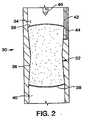
- FIG. 2 another plug apparatus 30 embodying principles of the present invention is representatively and schematically illustrated.
- the plug apparatus 30 is similar in many respects to the plug apparatus 10 described above, but differs in at least one substantial respect in that a plug member 32 thereof blocking fluid flow through a fluid passage 34 is constructed of a material 36 having a coating 38 applied thereto.
- the coating 38 isolates the material 32 from contact with a fluid 40 in the fluid passage 34.
- the material 32 may be at least partially soluble in a fluid 42 selectively introduced into contact with the material via another fluid passage 44 formed in the apparatus 30.
- the material 32 may be similar to the material 18 described above, or it may be another material, without departing from the principles of the present invention
- the coating 38 is preferably made of a material which is not soluble in the fluid 40.
- the coating 38 may be a non-water soluble plastic or polymeric material.
- the coating 38 could be made of polystyrene, polycarbonate, epoxy resin, etc.
- Beneficial results may be obtained by making the coating 38 of a relatively brittle material, so that the coating may be selectively fractured to thereby permit contact between the material 32 and the fluid 40.
- a rod, bar or other structure 46 could be lowered into the fluid passage 34 and impacted with the coating 38 to fracture the coating.
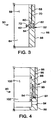
- a plug member 52 initially blocks flow through an opening or fluid passage 54 formed through a sidewall of a tubular housing 56 of the apparatus.
- the plug member 52 isolates an inner fluid passage 58 from communication with the exterior of the housing 56.
- the plug member 52 and opening 54 are specially constructed to resist a pressure differential directed from the exterior of the housing 56 to the fluid passage 58, but the plug member and opening could also be constructed to alternatively resist an oppositely directed pressure differential, or to resist pressure differentials from both directions.
- the plug member 52 includes a material 60, which may be similar to the materials 18, 36 described above.
- the material 60 may have a coating 62 isolating the material 60 from contact with fluid 64 in the fluid passage 58 and/or from contact with fluid 66 external to the housing 56.
- a fluid 68 in which at least a portion of the material 60 is soluble may be selectively introduced into contact with the material via a fluid passage 70 formed in the apparatus 50, or the material may be placed into contact with one or both of the fluids 64, 66.
- a rod, bar or other structure such as the structure 46 shown in FIG. 2, may be lowered in the fluid passage 58 and impacted with an inwardly extending portion 72 of the plug member 52.
- Such application of force to the portion 72 by the structure will cause fracture of the coating 62, or complete dislocation of the portion 72 from the remainder of the plug member 52, thereby permitting contact between the fluid 64 and the material 60.
- either or both of the plug members 32, 52 described above may be constructed to have a predetermined strength, so that when a predetermined pressure differential is created across the plug member, the material 36, 60 will break, thereby permitting flow through the respective fluid passage 34, 54.
- FIG. 4 another apparatus 80 embodying principles of the present invention is representatively and schematically illustrated.
- the apparatus 80 is depicted as including a valve 82 for selectively permitting and preventing flow through an opening or fluid passage 84 formed through a housing 86 of the valve.
- the apparatus 80 is merely representative of a wide variety of types of apparatus which may embody principles of the present invention.
- an apparatus constructed in accordance with the principles of the present invention does not necessarily include a valve or other flow control device.
- the valve 82 includes a displacement member or sleeve 88, which displaces relative to the housing 86 in operation of the apparatus 80.
- the sleeve 88 is a closure member which permits flow through the opening 84 when the sleeve is positioned as shown in FIG. 4, but which prevents flow through the opening when it is downwardly displaced relative to the housing 86.
- a spring or other bias member 90 biases the sleeve 88 downward, but the sleeve is prevented from displacing downwardly by a blocking member 92.
- the blocking member 92 includes a material 94 which may be similar to any of the materials 18, 36, 60 described above.
- the blocking member 92 may be dispersed, to thereby permit the bias member 90 to downwardly displace the sleeve 88 relative to the housing 86, by selectively introducing a fluid 96 into contact with the material via a fluid passage 98 formed in the apparatus 80.
- a portion (similar to portion 72 shown in FIG. 3) of the blocking member 92 could extend inwardly into an inner fluid passage 100 formed through the apparatus 80, so that a structure (similar to structure 46 shown in FIG. 2) could impact the blocking member and thereby provide contact between the material 94 and a fluid 102 in the fluid passage 100.
- the material 94 When the fluid 96 and/or fluid 102 contacts the material 94, the material at least partially dissolves in the fluid, thereby permitting the blocking member 92 to be dispersed sufficiently for the bias member 90 to displace the sleeve 88 downwardly, so that flow is prevented through the opening 84.
- the blocking member 92 may be constructed with a predetermined strength, so that when a predetermined force is applied to the blocking member, for example, by the bias member 90, the material 94 will break, thereby permitting displacement of the displacement member 88 in operation of the apparatus 80.
- the materials 18, 36, 60 and 94 may include a polymer material soluble in a fluid.
- the material may be a mixture of a water soluble polymer, such as polyacrylic acid, along with salt and/or sand.
- an acceptable material results from a mixture of 100 g acrylic acid, 700 g salt of 14/20 grain size, along with 0.1 g of a polymerization initiator dissolved in 5 ml water, or a proportionate multiplication of these constituents.
- the initiator may, for example, be 2,2'-Azobis (N,N'-dimethyleneisobutyramidine) dihydrochloride marketed by Wako under the trade name VA-044.
- Other acceptable material may result from the following examples of mixtures:
- the monomer is placed in a suitable container or mold and mixed with crack initiator material and/or other soluble material, such as sand and/or salt, if any. Nitrogen is bubbled through the mixture to remove Oxygen from the monomer solution. The initiator dissolved in water is then added to the mixture. The mixture is then heated to the appropriate polymerization temperature.
- crack initiator material and/or other soluble material such as sand and/or salt, if any.
- Nitrogen is bubbled through the mixture to remove Oxygen from the monomer solution.
- the initiator dissolved in water is then added to the mixture.
- the mixture is then heated to the appropriate polymerization temperature.
Landscapes
- Geology (AREA)
- Life Sciences & Earth Sciences (AREA)
- Engineering & Computer Science (AREA)
- Mining & Mineral Resources (AREA)
- Environmental & Geological Engineering (AREA)
- Fluid Mechanics (AREA)
- Physics & Mathematics (AREA)
- General Life Sciences & Earth Sciences (AREA)
- Geochemistry & Mineralogy (AREA)
- Addition Polymer Or Copolymer, Post-Treatments, Or Chemical Modifications (AREA)
- Pipe Accessories (AREA)
- Compositions Of Macromolecular Compounds (AREA)
- Closures For Containers (AREA)
Description
- The present invention relates generally to operations performed in conjunction with a subterranean well, and, more particularly, relates to a plug apparatus for use in a subterranean well. More specifically, the invention relates to a high strength water soluble plug.
- In EP0681087A, there is provided apparatus for temporarily closing a subterranean fluid conducting conduit, which apparatus comprises a tubular housing to be disposed within the fluid of a subterranean well; a temporary plug positioned within said housing for blocking fluid passage through said housing; a mechanical fracturing means for breaking said temporary plug so that fluid flow through said housing is permitted; said temporary plug being constructed at least partially from material dissolvable in the well fluid.
- In US4,018,286, a method for creating a plug in an underground formation penetrated by at least one well bore is provided in which a composition comprising water, a polymer capable of gelling in the presence of a crosslinking agent, and a crosslinking agent capable of gelling the polymer are admixed and injected into an underground formation while maintaining the pH of the fluids contacting the composition within the range of about 3 to about 7.
- In US 5,685,372, there is provided a method and apparatus for establishing and substantially destroying a fluid-type plug which is substantially dissolvable in fluid. The plug presents an upper convex surface and a lower convex surface, each of which is covered by a thin elastomeric membrane to protect the interior salt/sand portions of the plug from premature contact with well-bore fluids.
- For economy of manufacture, convenience of assembly and use, etc., it would be quite desirable to fabricate certain components of apparatus used in operations performed in conjunction with subterranean wells of soluble polymeric material. In this manner, operation of the apparatus could be controlled, at least in part, by controlling contact between the polymer and the fluid in which it is soluble.
- For example, it would be desirable to construct a plug apparatus in which a plug member blocking flow through a fluid passage included a soluble polymer. Subsequent contact between the polymer and the fluid in which it is soluble would enable the plug member to be dispersed, thereby permitting flow through the fluid passage.
- As another example, it would be desirable to construct an apparatus in which a displacement member displaces in operation of the apparatus, and in which a blocking member blocks displacement of the displacement member. Subsequent contact between the polymer and the fluid in which it is soluble would permit displacement of the displacement member, thereby controlling operation of the apparatus.
- Therefore, it would be advantageous to provide apparatus in which a soluble polymer is utilized to control, at least in part, operation of the apparatus. It is accordingly an object of the present invention to provide such apparatus.
- In carrying out the principles of the present invention, in accordance with embodiments thereof, apparatus is provided which is used in conjunction with operations performed in a subterranean well. In one embodiment, a plug member of a plug apparatus includes a soluble polymer. In another embodiment, an apparatus blocking member, which includes a soluble polymer, blocks displacement of a displacement member.
- In one aspect of the present invention, there is provided a plug apparatus for use in conjunction with operations performed in a subterranean well, comprising: a plug member, characterised in that the plug member includes a polymer soluble in a fluid and a coating of a material insoluble in the fluid, the coating material isolating the polymer from contact with the fluid.
- The fluid can be placed in contact with the soluble polymer, thereby permitting the plug member to be dispersed and permitting flow through the fluid passage. The plug member may also include other soluble material, such as salt, and crack initiator material, such as sand.
- In an embodiment, the polymer is soluble in the fluid present in a first fluid passage blocked by the plug member.
- In an embodiment, the polymer is soluble in the fluid present in a first fluid passage, the plug member blocking fluid flow through a second fluid passage.
- In an embodiment, the plug member is constructed of a mixture of the polymer and a second material soluble in the fluid. The second soluble material may be salt.
- In an embodiment, the plug member is constructed of a mixture of the polymer and a crack initiation material. The crack initiation material may be a granular material, such as sand or salt.
- In an embodiment, the coating material may fracture and permit contact between the fluid and the polymer in response to a force applied to the plug member. The coating material may be a selected one of a plastic and a polymeric material. For example, the coating material may be a selected one of a polystyrene, polycarbonate and epoxy material.
- In an embodiment, the polymer is a water soluble polymer. For example, the polymer may be a polyacrylic acid. The polymer may be a polymerized vinyl monomer.
- In an embodiment, the polymer is one or more of acrylic acid; 2-hydroxyethylacrylate, vinyl pyrrolidone, and N,N-dimethylacrylamide.
- In an embodiment, the polymer is one or more of a copolymer and a terpolymer.
- In an embodiment, the plug member blocks flow of the fluid through a fluid passage extending through the plug apparatus.
- In an embodiment, the plug member blocks fluid flow through a sidewall of the apparatus.
- In another aspect of the present invention, there is provided an apparatus for use in operations performed in conjunction with a subterranean well, the apparatus comprising: a displacement member, the displacement member displacing in operation of the apparatus; and a blocking member preventing displacement of the displacement member, the blocking member being a polymer soluble in a fluid present proximate the apparatus, the blocking member including a coating of a material insoluble in the fluid, the coating material isolating the polymer from contact with the fluid. In an embodiment of the apparatus disclosed herein, the apparatus is a valve in which displacement of a closure member is blocked by a member constructed of a polymer soluble in a fluid. The fluid can be placed in contact with the soluble polymer, thereby permitting the closure member to displace and operate the valve.
- The valve may selectively permitting and preventing flow through a fluid passage in response to displacement of the displacement member.
- In an embodiment, the displacement member is positionable in a selected one of first and second positions, and the blocking member prevents displacement of the displacement member between the first and second positions.
- In an embodiment, the fluid passage may formed through the apparatus. The fluid passage may be formed through a sidewall of the apparatus.
- In an embodiment, the displacement member is the closure operative to selectively permit and prevent flow through a fluid passage. The closure may selectively permit and prevent flow of the fluid.
- In an embodiment, the polymer is soluble in the fluid present in a first fluid passage, the displacement member blocking fluid flow through a second fluid passage.
- The material of construction of the blocking member may be the same as the plug member described above.
- Reference is now made to the accompanying drawings, in which:
- FIG. 1 is a quarter-sectional view of a first embodiment of an apparatus according to the present invention;
- FIG. 2 is a schematic cross-sectional view of a second embodiment of an apparatus according to the present invention;
- FIG. 3 is a schematic quarter-sectional view of a third embodiment of an apparatus according to the present invention; and
- FIG. 4 is a schematic quarter-sectional view of a fourth embodiment of an apparatus according to the present invention.
- Representatively illustrated in FIG. 1 is a
plug apparatus 10 which embodies principles of the present invention. In the following description of theplug apparatus 10 and other apparatus and methods described herein, directional terms, such as "above", "below", "upper", "lower", etc., are used for convenience in referring to the accompanying drawings. Additionally, it is to be understood that the various embodiments of the present invention described herein may be utilized in various orientations, such as inclined, inverted, horizontal, vertical, etc., without departing from the principles of the present invention. - The
plug apparatus 10 is similar in many respects to the plug apparatus described in EP-A-0939194. - The
plug apparatus 10 includes anouter housing 16 and aplug member 12, which blocks flow through afluid passage 14 formed generally axially through the plug apparatus. Theplug member 12 includes amaterial 18, andclosures closures material 18 andfluid 24 in thefluid passage 14. - To permit flow through the
fluid passage 14, thematerial 18 is contacted with a fluid in which at least a part of the material is soluble. Thematerial 18 may be at least partially soluble in thefluid 24 in thefluid passage 14, and/or the material may be soluble inanother fluid 26, which may be selectively introduced into contact with the material via anotherfluid passage 28 formed in theplug apparatus 10. Thematerial 18 is contacted with a fluid in which it is soluble, thereby weakening the material and permitting the material to be dispersed by, for example, creating a pressure differential across theplug member 12, thereby expelling theclosures material 18. - In this embodiment of the present invention, the
material 18 is a soluble polymer. Specifically, thematerial 18 may include a water soluble polymer, such as polyacrylic acid. However, the polymer may be produced from any water soluble monomer which can be polymerized to form a water soluble polymer. For example, the monomer may be acrylic acid, 2-hydroxyethylacrylate, vinyl pyrrolidone, N,N-dimethylacrylamide, etc. Additionally, copolymers, terpolymers, or any combination of water soluble monomers could be used. - Other components may be included in the
material 18. For example, thematerial 18 may include a material which aids in the formation of crack propagation sites, so that the material may be easily broken up for dispersal. An acceptable crack initiation material is sand. Another acceptable crack initiation material is salt, which is also water soluble, and which also aids in the formation of voids in the material if the fluid brought into contact with the material is water. - Referring additionally now to FIG. 2, another
plug apparatus 30 embodying principles of the present invention is representatively and schematically illustrated. Theplug apparatus 30 is similar in many respects to theplug apparatus 10 described above, but differs in at least one substantial respect in that aplug member 32 thereof blocking fluid flow through afluid passage 34 is constructed of a material 36 having acoating 38 applied thereto. - The
coating 38 isolates the material 32 from contact with a fluid 40 in thefluid passage 34. However, thematerial 32 may be at least partially soluble in a fluid 42 selectively introduced into contact with the material via anotherfluid passage 44 formed in theapparatus 30. Thematerial 32 may be similar to the material 18 described above, or it may be another material, without departing from the principles of the present invention - The
coating 38 is preferably made of a material which is not soluble in thefluid 40. Thecoating 38 may be a non-water soluble plastic or polymeric material. For example, thecoating 38 could be made of polystyrene, polycarbonate, epoxy resin, etc. - Beneficial results may be obtained by making the
coating 38 of a relatively brittle material, so that the coating may be selectively fractured to thereby permit contact between the material 32 and the fluid 40. For example, a rod, bar orother structure 46 could be lowered into thefluid passage 34 and impacted with thecoating 38 to fracture the coating. - Referring additionally now to FIG. 3, another
apparatus 50 embodying principles of the present invention is representatively and schematically illustrated. In theapparatus 50, aplug member 52 initially blocks flow through an opening orfluid passage 54 formed through a sidewall of atubular housing 56 of the apparatus. Theplug member 52 isolates aninner fluid passage 58 from communication with the exterior of thehousing 56. As shown in FIG. 3, theplug member 52 andopening 54 are specially constructed to resist a pressure differential directed from the exterior of thehousing 56 to thefluid passage 58, but the plug member and opening could also be constructed to alternatively resist an oppositely directed pressure differential, or to resist pressure differentials from both directions. - The
plug member 52 includes amaterial 60, which may be similar to thematerials material 60 may have acoating 62 isolating the material 60 from contact withfluid 64 in thefluid passage 58 and/or from contact withfluid 66 external to thehousing 56. - To disperse the
plug member 52 and thereby permit flow through theopening 54, a fluid 68 in which at least a portion of thematerial 60 is soluble may be selectively introduced into contact with the material via afluid passage 70 formed in theapparatus 50, or the material may be placed into contact with one or both of thefluids structure 46 shown in FIG. 2, may be lowered in thefluid passage 58 and impacted with an inwardly extendingportion 72 of theplug member 52. Such application of force to theportion 72 by the structure will cause fracture of thecoating 62, or complete dislocation of theportion 72 from the remainder of theplug member 52, thereby permitting contact between the fluid 64 and thematerial 60. - Note that either or both of the
plug members material respective fluid passage - Referring additionally nowto FIG. 4, another
apparatus 80 embodying principles of the present invention is representatively and schematically illustrated. Theapparatus 80 is depicted as including avalve 82 for selectively permitting and preventing flow through an opening orfluid passage 84 formed through ahousing 86 of the valve. However, it is to be clearly understood that theapparatus 80 is merely representative of a wide variety of types of apparatus which may embody principles of the present invention. For example, an apparatus constructed in accordance with the principles of the present invention does not necessarily include a valve or other flow control device. - The
valve 82 includes a displacement member orsleeve 88, which displaces relative to thehousing 86 in operation of theapparatus 80. Specifically, thesleeve 88 is a closure member which permits flow through theopening 84 when the sleeve is positioned as shown in FIG. 4, but which prevents flow through the opening when it is downwardly displaced relative to thehousing 86. A spring orother bias member 90 biases thesleeve 88 downward, but the sleeve is prevented from displacing downwardly by a blockingmember 92. - The blocking
member 92 includes a material 94 which may be similar to any of thematerials member 92 may be dispersed, to thereby permit thebias member 90 to downwardly displace thesleeve 88 relative to thehousing 86, by selectively introducing a fluid 96 into contact with the material via a fluid passage 98 formed in theapparatus 80. Alternatively, a portion (similar toportion 72 shown in FIG. 3) of the blockingmember 92 could extend inwardly into aninner fluid passage 100 formed through theapparatus 80, so that a structure (similar to structure 46 shown in FIG. 2) could impact the blocking member and thereby provide contact between the material 94 and a fluid 102 in thefluid passage 100. When the fluid 96 and/orfluid 102 contacts thematerial 94, the material at least partially dissolves in the fluid, thereby permitting the blockingmember 92 to be dispersed sufficiently for thebias member 90 to displace thesleeve 88 downwardly, so that flow is prevented through theopening 84. - Note that the blocking
member 92 may be constructed with a predetermined strength, so that when a predetermined force is applied to the blocking member, for example, by thebias member 90, thematerial 94 will break, thereby permitting displacement of thedisplacement member 88 in operation of theapparatus 80. - As described above, the
materials - For example, the applicants have found that an acceptable material results from a mixture of 100 g acrylic acid, 700 g salt of 14/20 grain size, along with 0.1 g of a polymerization initiator dissolved in 5 ml water, or a proportionate multiplication of these constituents. The initiator may, for example, be 2,2'-Azobis (N,N'-dimethyleneisobutyramidine) dihydrochloride marketed by Wako under the trade name VA-044. Other acceptable material may result from the following examples of mixtures:
- a) 45 g acrylic acid, 200 g sand of 20/40 grain size, along with 0.15 g polymerization initiator dissolved in 5 ml water;
- b) 100 g acrylic acid, 700 g sand of 20/40 grain size, along with 0.3 g polymerization initiator dissolved in 3 ml water;
- c) 100 g acrylic acid, 700 g salt of 14/20 grain size, along with 0.3 g polymerization initiator dissolved in 5 ml water;
- d) 100 g acrylic acid, 700 g salt of 14/20 grain size, along with 0.6 g polymerization initiator dissolved in 5 ml water;
- e) 100 g acrylic acid, 350 g sand of 20/40 grain size, 350 g salt of 14/20 grain size, along with 0.3 g polymerization initiator dissolved in 5 ml water;
- f) 100 g acrylic acid, 700 g salt of 14/20 grain size, along with 0.3 g polymerization initiator dissolved in 3 ml water;
- g) 100 g acrylic acid, 700 g salt of 20/40 grain size, along with 0.3 g polymerization initiator dissolved in 3 ml water; and
- h) 100 g acrylic acid, 350 g sand of 20/40 grain size, 350 g salt of 20/40 grain size, along with 0.3 g polymerization initiator dissolved in 3 ml water.
- To prepare the material, the monomer is placed in a suitable container or mold and mixed with crack initiator material and/or other soluble material, such as sand and/or salt, if any. Nitrogen is bubbled through the mixture to remove Oxygen from the monomer solution. The initiator dissolved in water is then added to the mixture. The mixture is then heated to the appropriate polymerization temperature.
- It will be appreciated that the invention described above may be modified.
Claims (8)
- A plug apparatus (10, 30) for use in conjunction with operations performed in a subterranean well, comprising: a plug member (12, 32), characterised in that the plug member (12, 32) includes a polymer (18, 36) soluble in a fluid and a coating (20, 38) of a material insoluble in the fluid, the coating material isolating the polymer from contact with the fluid.
- A plug apparatus (10, 30) according to Claim 1, wherein the plug member (12,32) is constructed of a mixture of the polymer (18, 36) and a second material soluble in the fluid.
- A plug apparatus (10, 30) according to Claim 1 or 2, wherein the plug member (12, 32) is constructed of a mixture of the polymer (18, 36) and a crack initiation material.
- A plug apparatus according to Claim 1, wherein the polymer (18, 36) is a polymerized vinyl monomer.
- An apparatus (80) for use in operations performed in conjunction with a subterranean well, characterised in that the apparatus comprises: a displacement member (88), the displacement member (88) displacing in operation of the apparatus (80); and a blocking member (92) preventing displacement of the displacement member (88), the blocking member (92) being a polymer soluble in a fluid present proximate the apparatus, the blocking member including a coating (20, 38) of a material insoluble in the fluid, the coating material isolating the polymer from contact with the fluid.
- Apparatus (80) according to Claim 5, further comprising a valve (82) selectively permitting and preventing flow through a fluid passage (84) in response to displacement of the displacement member (88).
- Apparatus (80) according to Claim 5, wherein the displacement member (88) is a closure operative to selectively permit and prevent flow through a fluid passage.
- Apparatus according to Claim 5, 6 or 7, wherein the blocking member (92) is constructed of a mixture of the polymer and a crack initiation material.
Applications Claiming Priority (2)
| Application Number | Priority Date | Filing Date | Title |
|---|---|---|---|
| US09/204,619 US6220350B1 (en) | 1998-12-01 | 1998-12-01 | High strength water soluble plug |
| US204619 | 1998-12-01 |
Publications (3)
| Publication Number | Publication Date |
|---|---|
| EP1006258A2 EP1006258A2 (en) | 2000-06-07 |
| EP1006258A3 EP1006258A3 (en) | 2001-04-11 |
| EP1006258B1 true EP1006258B1 (en) | 2006-03-01 |
Family
ID=22758689
Family Applications (1)
| Application Number | Title | Priority Date | Filing Date |
|---|---|---|---|
| EP99309269A Expired - Lifetime EP1006258B1 (en) | 1998-12-01 | 1999-11-22 | Plug apparatus for use in a subterranean well |
Country Status (3)
| Country | Link |
|---|---|
| US (1) | US6220350B1 (en) |
| EP (1) | EP1006258B1 (en) |
| DE (1) | DE69930077D1 (en) |
Families Citing this family (127)
| Publication number | Priority date | Publication date | Assignee | Title |
|---|---|---|---|---|
| US6161622A (en) * | 1998-11-02 | 2000-12-19 | Halliburton Energy Services, Inc. | Remote actuated plug method |
| US8403037B2 (en) | 2009-12-08 | 2013-03-26 | Baker Hughes Incorporated | Dissolvable tool and method |
| US9079246B2 (en) | 2009-12-08 | 2015-07-14 | Baker Hughes Incorporated | Method of making a nanomatrix powder metal compact |
| US8327931B2 (en) | 2009-12-08 | 2012-12-11 | Baker Hughes Incorporated | Multi-component disappearing tripping ball and method for making the same |
| US9682425B2 (en) | 2009-12-08 | 2017-06-20 | Baker Hughes Incorporated | Coated metallic powder and method of making the same |
| US9101978B2 (en) | 2002-12-08 | 2015-08-11 | Baker Hughes Incorporated | Nanomatrix powder metal compact |
| US9109429B2 (en) | 2002-12-08 | 2015-08-18 | Baker Hughes Incorporated | Engineered powder compact composite material |
| US6926086B2 (en) * | 2003-05-09 | 2005-08-09 | Halliburton Energy Services, Inc. | Method for removing a tool from a well |
| US20040231845A1 (en) * | 2003-05-15 | 2004-11-25 | Cooke Claude E. | Applications of degradable polymers in wells |
| US20090107684A1 (en) * | 2007-10-31 | 2009-04-30 | Cooke Jr Claude E | Applications of degradable polymers for delayed mechanical changes in wells |
| US7350582B2 (en) * | 2004-12-21 | 2008-04-01 | Weatherford/Lamb, Inc. | Wellbore tool with disintegratable components and method of controlling flow |
| NO325431B1 (en) * | 2006-03-23 | 2008-04-28 | Bjorgum Mekaniske As | Soluble sealing device and method thereof. |
| US7325617B2 (en) * | 2006-03-24 | 2008-02-05 | Baker Hughes Incorporated | Frac system without intervention |
| US20070272414A1 (en) * | 2006-05-26 | 2007-11-29 | Palmer Larry T | Method of riser deployment on a subsea wellhead |
| US20080257549A1 (en) * | 2006-06-08 | 2008-10-23 | Halliburton Energy Services, Inc. | Consumable Downhole Tools |
| US20070284097A1 (en) | 2006-06-08 | 2007-12-13 | Halliburton Energy Services, Inc. | Consumable downhole tools |
| US7591318B2 (en) * | 2006-07-20 | 2009-09-22 | Halliburton Energy Services, Inc. | Method for removing a sealing plug from a well |
| US7464764B2 (en) * | 2006-09-18 | 2008-12-16 | Baker Hughes Incorporated | Retractable ball seat having a time delay material |
| US7726406B2 (en) * | 2006-09-18 | 2010-06-01 | Yang Xu | Dissolvable downhole trigger device |
| GB0618687D0 (en) * | 2006-09-22 | 2006-11-01 | Omega Completion Technology | Erodeable pressure barrier |
| US20080202764A1 (en) | 2007-02-22 | 2008-08-28 | Halliburton Energy Services, Inc. | Consumable downhole tools |
| US8157012B2 (en) * | 2007-09-07 | 2012-04-17 | Frazier W Lynn | Downhole sliding sleeve combination tool |
| US8544548B2 (en) | 2007-10-19 | 2013-10-01 | Baker Hughes Incorporated | Water dissolvable materials for activating inflow control devices that control flow of subsurface fluids |
| US20090101344A1 (en) * | 2007-10-22 | 2009-04-23 | Baker Hughes Incorporated | Water Dissolvable Released Material Used as Inflow Control Device |
| US9194209B2 (en) | 2007-12-03 | 2015-11-24 | W. Lynn Frazier | Hydraulicaly fracturable downhole valve assembly and method for using same |
| US7806189B2 (en) | 2007-12-03 | 2010-10-05 | W. Lynn Frazier | Downhole valve assembly |
| US7708066B2 (en) * | 2007-12-21 | 2010-05-04 | Frazier W Lynn | Full bore valve for downhole use |
| NO328577B1 (en) * | 2008-04-08 | 2010-03-22 | Tco As | Device by plug |
| US20090255691A1 (en) * | 2008-04-10 | 2009-10-15 | Baker Hughes Incorporated | Permanent packer using a slurry inflation medium |
| US7775286B2 (en) * | 2008-08-06 | 2010-08-17 | Baker Hughes Incorporated | Convertible downhole devices and method of performing downhole operations using convertible downhole devices |
| US8267177B1 (en) | 2008-08-15 | 2012-09-18 | Exelis Inc. | Means for creating field configurable bridge, fracture or soluble insert plugs |
| US7900696B1 (en) | 2008-08-15 | 2011-03-08 | Itt Manufacturing Enterprises, Inc. | Downhole tool with exposable and openable flow-back vents |
| NO20090520A (en) | 2009-02-03 | 2010-07-05 | Gustav Wee | Plug of brittle material that is crushable by mechanical action |
| US8276670B2 (en) * | 2009-04-27 | 2012-10-02 | Schlumberger Technology Corporation | Downhole dissolvable plug |
| US8261761B2 (en) * | 2009-05-07 | 2012-09-11 | Baker Hughes Incorporated | Selectively movable seat arrangement and method |
| US20100294515A1 (en) * | 2009-05-22 | 2010-11-25 | Baker Hughes Incorporated | Selective plug and method |
| US20100294514A1 (en) * | 2009-05-22 | 2010-11-25 | Baker Hughes Incorporated | Selective plug and method |
| US8272445B2 (en) * | 2009-07-15 | 2012-09-25 | Baker Hughes Incorporated | Tubular valve system and method |
| US8251154B2 (en) * | 2009-08-04 | 2012-08-28 | Baker Hughes Incorporated | Tubular system with selectively engagable sleeves and method |
| US8397823B2 (en) * | 2009-08-10 | 2013-03-19 | Baker Hughes Incorporated | Tubular actuator, system and method |
| US8291988B2 (en) * | 2009-08-10 | 2012-10-23 | Baker Hughes Incorporated | Tubular actuator, system and method |
| US8291980B2 (en) * | 2009-08-13 | 2012-10-23 | Baker Hughes Incorporated | Tubular valving system and method |
| US20110042099A1 (en) * | 2009-08-20 | 2011-02-24 | Halliburton Energy Services, Inc. | Remote Actuated Downhole Pressure Barrier and Method for Use of Same |
| US8479823B2 (en) * | 2009-09-22 | 2013-07-09 | Baker Hughes Incorporated | Plug counter and method |
| US8418769B2 (en) * | 2009-09-25 | 2013-04-16 | Baker Hughes Incorporated | Tubular actuator and method |
| US8316951B2 (en) * | 2009-09-25 | 2012-11-27 | Baker Hughes Incorporated | Tubular actuator and method |
| US8342094B2 (en) * | 2009-10-22 | 2013-01-01 | Schlumberger Technology Corporation | Dissolvable material application in perforating |
| US8646531B2 (en) * | 2009-10-29 | 2014-02-11 | Baker Hughes Incorporated | Tubular actuator, system and method |
| US8425651B2 (en) | 2010-07-30 | 2013-04-23 | Baker Hughes Incorporated | Nanomatrix metal composite |
| US9227243B2 (en) | 2009-12-08 | 2016-01-05 | Baker Hughes Incorporated | Method of making a powder metal compact |
| US9243475B2 (en) | 2009-12-08 | 2016-01-26 | Baker Hughes Incorporated | Extruded powder metal compact |
| US8528633B2 (en) | 2009-12-08 | 2013-09-10 | Baker Hughes Incorporated | Dissolvable tool and method |
| US8573295B2 (en) | 2010-11-16 | 2013-11-05 | Baker Hughes Incorporated | Plug and method of unplugging a seat |
| US10240419B2 (en) | 2009-12-08 | 2019-03-26 | Baker Hughes, A Ge Company, Llc | Downhole flow inhibition tool and method of unplugging a seat |
| US9127515B2 (en) | 2010-10-27 | 2015-09-08 | Baker Hughes Incorporated | Nanomatrix carbon composite |
| US20110155392A1 (en) * | 2009-12-30 | 2011-06-30 | Frazier W Lynn | Hydrostatic Flapper Stimulation Valve and Method |
| US8739881B2 (en) * | 2009-12-30 | 2014-06-03 | W. Lynn Frazier | Hydrostatic flapper stimulation valve and method |
| US8424610B2 (en) | 2010-03-05 | 2013-04-23 | Baker Hughes Incorporated | Flow control arrangement and method |
| US9279311B2 (en) * | 2010-03-23 | 2016-03-08 | Baker Hughes Incorporation | System, assembly and method for port control |
| US8430173B2 (en) | 2010-04-12 | 2013-04-30 | Halliburton Energy Services, Inc. | High strength dissolvable structures for use in a subterranean well |
| US8430174B2 (en) * | 2010-09-10 | 2013-04-30 | Halliburton Energy Services, Inc. | Anhydrous boron-based timed delay plugs |
| WO2011159523A2 (en) | 2010-06-14 | 2011-12-22 | Schlumberger Canada Limited | Method and apparatus for use with an inflow control device |
| US8776884B2 (en) | 2010-08-09 | 2014-07-15 | Baker Hughes Incorporated | Formation treatment system and method |
| US8789600B2 (en) | 2010-08-24 | 2014-07-29 | Baker Hughes Incorporated | Fracing system and method |
| US9090955B2 (en) | 2010-10-27 | 2015-07-28 | Baker Hughes Incorporated | Nanomatrix powder metal composite |
| US8579023B1 (en) | 2010-10-29 | 2013-11-12 | Exelis Inc. | Composite downhole tool with ratchet locking mechanism |
| US8833443B2 (en) | 2010-11-22 | 2014-09-16 | Halliburton Energy Services, Inc. | Retrievable swellable packer |
| US8668019B2 (en) * | 2010-12-29 | 2014-03-11 | Baker Hughes Incorporated | Dissolvable barrier for downhole use and method thereof |
| US8662162B2 (en) | 2011-02-03 | 2014-03-04 | Baker Hughes Incorporated | Segmented collapsible ball seat allowing ball recovery |
| US8668018B2 (en) | 2011-03-10 | 2014-03-11 | Baker Hughes Incorporated | Selective dart system for actuating downhole tools and methods of using same |
| US8668006B2 (en) | 2011-04-13 | 2014-03-11 | Baker Hughes Incorporated | Ball seat having ball support member |
| US8770276B1 (en) | 2011-04-28 | 2014-07-08 | Exelis, Inc. | Downhole tool with cones and slips |
| US8631876B2 (en) | 2011-04-28 | 2014-01-21 | Baker Hughes Incorporated | Method of making and using a functionally gradient composite tool |
| US9080098B2 (en) | 2011-04-28 | 2015-07-14 | Baker Hughes Incorporated | Functionally gradient composite article |
| US8479808B2 (en) | 2011-06-01 | 2013-07-09 | Baker Hughes Incorporated | Downhole tools having radially expandable seat member |
| US9145758B2 (en) | 2011-06-09 | 2015-09-29 | Baker Hughes Incorporated | Sleeved ball seat |
| US9139928B2 (en) | 2011-06-17 | 2015-09-22 | Baker Hughes Incorporated | Corrodible downhole article and method of removing the article from downhole environment |
| US9200502B2 (en) | 2011-06-22 | 2015-12-01 | Schlumberger Technology Corporation | Well-based fluid communication control assembly |
| US9707739B2 (en) | 2011-07-22 | 2017-07-18 | Baker Hughes Incorporated | Intermetallic metallic composite, method of manufacture thereof and articles comprising the same |
| US8783365B2 (en) | 2011-07-28 | 2014-07-22 | Baker Hughes Incorporated | Selective hydraulic fracturing tool and method thereof |
| US9643250B2 (en) | 2011-07-29 | 2017-05-09 | Baker Hughes Incorporated | Method of controlling the corrosion rate of alloy particles, alloy particle with controlled corrosion rate, and articles comprising the particle |
| US9833838B2 (en) | 2011-07-29 | 2017-12-05 | Baker Hughes, A Ge Company, Llc | Method of controlling the corrosion rate of alloy particles, alloy particle with controlled corrosion rate, and articles comprising the particle |
| US9057242B2 (en) | 2011-08-05 | 2015-06-16 | Baker Hughes Incorporated | Method of controlling corrosion rate in downhole article, and downhole article having controlled corrosion rate |
| US8622141B2 (en) | 2011-08-16 | 2014-01-07 | Baker Hughes Incorporated | Degradable no-go component |
| US9033055B2 (en) | 2011-08-17 | 2015-05-19 | Baker Hughes Incorporated | Selectively degradable passage restriction and method |
| US9109269B2 (en) | 2011-08-30 | 2015-08-18 | Baker Hughes Incorporated | Magnesium alloy powder metal compact |
| US9090956B2 (en) | 2011-08-30 | 2015-07-28 | Baker Hughes Incorporated | Aluminum alloy powder metal compact |
| US9856547B2 (en) | 2011-08-30 | 2018-01-02 | Bakers Hughes, A Ge Company, Llc | Nanostructured powder metal compact |
| US9643144B2 (en) | 2011-09-02 | 2017-05-09 | Baker Hughes Incorporated | Method to generate and disperse nanostructures in a composite material |
| US9133695B2 (en) | 2011-09-03 | 2015-09-15 | Baker Hughes Incorporated | Degradable shaped charge and perforating gun system |
| US9187990B2 (en) | 2011-09-03 | 2015-11-17 | Baker Hughes Incorporated | Method of using a degradable shaped charge and perforating gun system |
| US9347119B2 (en) | 2011-09-03 | 2016-05-24 | Baker Hughes Incorporated | Degradable high shock impedance material |
| US9284812B2 (en) | 2011-11-21 | 2016-03-15 | Baker Hughes Incorporated | System for increasing swelling efficiency |
| US9004091B2 (en) | 2011-12-08 | 2015-04-14 | Baker Hughes Incorporated | Shape-memory apparatuses for restricting fluid flow through a conduit and methods of using same |
| US9010416B2 (en) | 2012-01-25 | 2015-04-21 | Baker Hughes Incorporated | Tubular anchoring system and a seat for use in the same |
| US9016388B2 (en) | 2012-02-03 | 2015-04-28 | Baker Hughes Incorporated | Wiper plug elements and methods of stimulating a wellbore environment |
| US9068428B2 (en) | 2012-02-13 | 2015-06-30 | Baker Hughes Incorporated | Selectively corrodible downhole article and method of use |
| US9605508B2 (en) | 2012-05-08 | 2017-03-28 | Baker Hughes Incorporated | Disintegrable and conformable metallic seal, and method of making the same |
| US8997859B1 (en) | 2012-05-11 | 2015-04-07 | Exelis, Inc. | Downhole tool with fluted anvil |
| US9068411B2 (en) | 2012-05-25 | 2015-06-30 | Baker Hughes Incorporated | Thermal release mechanism for downhole tools |
| US9279295B2 (en) | 2012-06-28 | 2016-03-08 | Weatherford Technology Holdings, Llc | Liner flotation system |
| US9388333B2 (en) | 2012-07-11 | 2016-07-12 | Halliburton Energy Services, Inc. | Methods relating to designing wellbore strengthening fluids |
| NO337410B1 (en) * | 2012-07-23 | 2016-04-11 | Plugtech As | Plug for temporary installation in a well |
| NO2877678T3 (en) * | 2012-08-31 | 2018-04-28 | ||
| CA2819681C (en) | 2013-02-05 | 2019-08-13 | Ncs Oilfield Services Canada Inc. | Casing float tool |
| US9359863B2 (en) | 2013-04-23 | 2016-06-07 | Halliburton Energy Services, Inc. | Downhole plug apparatus |
| US9441437B2 (en) * | 2013-05-16 | 2016-09-13 | Halliburton Energy Services, Inc. | Electronic rupture discs for interventionless barrier plug |
| US9677349B2 (en) | 2013-06-20 | 2017-06-13 | Baker Hughes Incorporated | Downhole entry guide having disappearing profile and methods of using same |
| CA2917042C (en) | 2013-07-01 | 2020-06-09 | Conocophillips Company | Fusible alloy plug in flow control device |
| US9816339B2 (en) | 2013-09-03 | 2017-11-14 | Baker Hughes, A Ge Company, Llc | Plug reception assembly and method of reducing restriction in a borehole |
| US20150191986A1 (en) * | 2014-01-09 | 2015-07-09 | Baker Hughes Incorporated | Frangible and disintegrable tool and method of removing a tool |
| US10018010B2 (en) * | 2014-01-24 | 2018-07-10 | Baker Hughes, A Ge Company, Llc | Disintegrating agglomerated sand frack plug |
| WO2015127174A1 (en) | 2014-02-21 | 2015-08-27 | Terves, Inc. | Fluid activated disintegrating metal system |
| US11167343B2 (en) | 2014-02-21 | 2021-11-09 | Terves, Llc | Galvanically-active in situ formed particles for controlled rate dissolving tools |
| US10400535B1 (en) | 2014-03-24 | 2019-09-03 | Nine Downhole Technologies, Llc | Retrievable downhole tool |
| US9915114B2 (en) | 2015-03-24 | 2018-03-13 | Donald R. Greenlee | Retrievable downhole tool |
| US20160138370A1 (en) * | 2014-11-18 | 2016-05-19 | Baker Hughes Incorporated | Mechanical diverter |
| US10287829B2 (en) | 2014-12-22 | 2019-05-14 | Colorado School Of Mines | Method and apparatus to rotate subsurface wellbore casing |
| US9910026B2 (en) | 2015-01-21 | 2018-03-06 | Baker Hughes, A Ge Company, Llc | High temperature tracers for downhole detection of produced water |
| US10378303B2 (en) | 2015-03-05 | 2019-08-13 | Baker Hughes, A Ge Company, Llc | Downhole tool and method of forming the same |
| US9845658B1 (en) | 2015-04-17 | 2017-12-19 | Albany International Corp. | Lightweight, easily drillable or millable slip for composite frac, bridge and drop ball plugs |
| US10221637B2 (en) | 2015-08-11 | 2019-03-05 | Baker Hughes, A Ge Company, Llc | Methods of manufacturing dissolvable tools via liquid-solid state molding |
| US10016810B2 (en) | 2015-12-14 | 2018-07-10 | Baker Hughes, A Ge Company, Llc | Methods of manufacturing degradable tools using a galvanic carrier and tools manufactured thereof |
| US10316611B2 (en) | 2016-08-24 | 2019-06-11 | Kevin David Wutherich | Hybrid bridge plug |
| CA3012511A1 (en) | 2017-07-27 | 2019-01-27 | Terves Inc. | Degradable metal matrix composite |
| CA3113055C (en) | 2018-09-20 | 2022-09-27 | Conocophillips Company | Dissolvable thread tape and plugs for wells |
| US11293252B2 (en) * | 2020-04-16 | 2022-04-05 | Halliburton Energy Services, Inc. | Fluid barriers for dissolvable plugs |
Family Cites Families (43)
| Publication number | Priority date | Publication date | Assignee | Title |
|---|---|---|---|---|
| US3306870A (en) * | 1964-06-01 | 1967-02-28 | Dow Chemical Co | Fluid gelable composition of acrylamide polymers and aqueous solutions of inorganic hydroxides and salts |
| US3447608A (en) * | 1966-04-15 | 1969-06-03 | Dow Chemical Co | Open hole cement plugging |
| US3362476A (en) | 1966-10-10 | 1968-01-09 | Marathon Oil Co | Process and device for restoring lost circulation |
| US3762473A (en) * | 1972-07-25 | 1973-10-02 | Dresser Ind | Well instrument positioning device |
| US3861467A (en) | 1973-12-28 | 1975-01-21 | Texaco Inc | Permeable cementing method |
| US4018286A (en) * | 1975-11-06 | 1977-04-19 | Phillips Petroleum Company | Controlled well plugging with dilute polymer solutions |
| US4186803A (en) | 1976-10-26 | 1980-02-05 | Texas Brine Corporation | Well completion and work over method |
| US4160484A (en) | 1978-01-16 | 1979-07-10 | Camco, Incorporated | Surface control well safety valve |
| US4154303A (en) | 1978-02-13 | 1979-05-15 | The Dow Chemical Company | Valve assembly for controlling liquid flow in a wellbore |
| US4183406A (en) * | 1978-08-01 | 1980-01-15 | Exxon Production Research Company | Method of treating a borehole using gellable polymers |
| US4216830A (en) | 1978-11-02 | 1980-08-12 | Otis Engineering Corporation | Flapper valve |
| US4374543A (en) | 1980-08-19 | 1983-02-22 | Tri-State Oil Tool Industries, Inc. | Apparatus for well treating |
| US4433702A (en) | 1981-07-06 | 1984-02-28 | Baker International Corporation | Fully opening flapper valve apparatus |
| US4423773A (en) | 1981-07-17 | 1984-01-03 | Baker International Corporation | Single acting subterranean well valve assembly with conduit fluid stripping means |
| US4378049A (en) | 1981-08-21 | 1983-03-29 | Halliburton Company | Methods, additives and compositions for temporarily sealing high temperature permeable formations |
| US4428427A (en) | 1981-12-03 | 1984-01-31 | Getty Oil Company | Consolidatable gravel pack method |
| US4500357A (en) * | 1984-04-03 | 1985-02-19 | Halliburton Company | Oil field cementing methods and compositions |
| US4888240A (en) | 1984-07-02 | 1989-12-19 | Graham John W | High strength particulates |
| SE439814B (en) * | 1984-07-18 | 1985-07-01 | Karl Gustav Hesselmar | FIXING MACHINE, FOR FIXING IN SPACES, THAT WILL BE EXPANDED TO FIXING MACHINE BY ENVIRONMENTAL EFFECT |
| US4541484A (en) | 1984-08-29 | 1985-09-17 | Baker Oil Tools, Inc. | Combination gravel packing device and method |
| US4597445A (en) | 1985-02-19 | 1986-07-01 | Camco, Incorporated | Well subsurface safety valve |
| US4603741A (en) * | 1985-02-19 | 1986-08-05 | Hughes Tool Company | Weight actuated tubing valve |
| US4691775A (en) | 1986-03-25 | 1987-09-08 | Dresser Industries, Inc. | Isolation valve with frangible flapper element |
| NZ218143A (en) | 1986-06-10 | 1989-03-29 | Takenaka Komuten Co | Annular paper capsule with lugged frangible plate for conveying plugging agent to borehole drilling fluid sink |
| US4813481A (en) | 1987-08-27 | 1989-03-21 | Otis Engineering Corporation | Expendable flapper valve |
| US4817720A (en) | 1987-12-18 | 1989-04-04 | Texaco Inc. | Method for forming a barrier to fluid flow in an oil formation adjacent to a producing oil well |
| US4898750A (en) | 1988-12-05 | 1990-02-06 | Texaco Inc. | Processes for forming and using particles coated with a resin which is resistant to high temperature and high pH aqueous environments |
| DE69013059D1 (en) * | 1989-06-06 | 1994-11-10 | Pumptech Nv | Method and device for temporarily sealing pipelines. |
| CA2073332C (en) * | 1990-01-17 | 1999-09-28 | Paul Douglas Maxfield Gullet | Centralizers for oil well casings |
| US5188182A (en) | 1990-07-13 | 1993-02-23 | Otis Engineering Corporation | System containing expendible isolation valve with frangible sealing member, seat arrangement and method for use |
| GB9028185D0 (en) | 1990-12-29 | 1991-02-13 | Well Equip Ltd | A release mechanism |
| US5188183A (en) | 1991-05-03 | 1993-02-23 | Baker Hughes Incorporated | Method and apparatus for controlling the flow of well bore fluids |
| US5441111A (en) | 1992-01-09 | 1995-08-15 | Petroleum Engineering Services Limited | Bridge plug |
| US5181569A (en) | 1992-03-23 | 1993-01-26 | Otis Engineering Corporation | Pressure operated valve |
| US5404556A (en) | 1992-06-15 | 1995-04-04 | California Institute Of Technology | Apparatus for carrying out asynchronous communication among integrated circuits |
| US5417285A (en) | 1992-08-07 | 1995-05-23 | Baker Hughes Incorporated | Method and apparatus for sealing and transferring force in a wellbore |
| US5484020A (en) * | 1994-04-25 | 1996-01-16 | Shell Oil Company | Remedial wellbore sealing with unsaturated monomer system |
| US5479986A (en) * | 1994-05-02 | 1996-01-02 | Halliburton Company | Temporary plug system |
| GB9425240D0 (en) * | 1994-12-14 | 1995-02-08 | Head Philip | Dissoluable metal to metal seal |
| US5607017A (en) | 1995-07-03 | 1997-03-04 | Pes, Inc. | Dissolvable well plug |
| NO980072L (en) * | 1997-01-13 | 1998-07-14 | Halliburton Energy Serv Inc | Detachable movable release release mechanism |
| US5947204A (en) * | 1997-09-23 | 1999-09-07 | Dresser Industries, Inc. | Production fluid control device and method for oil and/or gas wells |
| US6076600A (en) | 1998-02-27 | 2000-06-20 | Halliburton Energy Services, Inc. | Plug apparatus having a dispersible plug member and a fluid barrier |
-
1998
- 1998-12-01 US US09/204,619 patent/US6220350B1/en not_active Expired - Lifetime
-
1999
- 1999-11-22 EP EP99309269A patent/EP1006258B1/en not_active Expired - Lifetime
- 1999-11-22 DE DE69930077T patent/DE69930077D1/en not_active Expired - Lifetime
Also Published As
| Publication number | Publication date |
|---|---|
| EP1006258A3 (en) | 2001-04-11 |
| EP1006258A2 (en) | 2000-06-07 |
| US6220350B1 (en) | 2001-04-24 |
| DE69930077D1 (en) | 2006-04-27 |
Similar Documents
| Publication | Publication Date | Title |
|---|---|---|
| EP1006258B1 (en) | Plug apparatus for use in a subterranean well | |
| RU2452554C2 (en) | Differential filters to arrest water in oil production | |
| US5372195A (en) | Method for directional hydraulic fracturing | |
| US7520327B2 (en) | Methods and materials for subterranean fluid forming barriers in materials surrounding wells | |
| US6171386B1 (en) | Cementing compositions, a method of making therefor, and a method for cementing wells | |
| CA2612121C (en) | Methods and materials for zonal isolation | |
| US5479986A (en) | Temporary plug system | |
| US7938191B2 (en) | Method and apparatus for controlling elastomer swelling in downhole applications | |
| US3954629A (en) | Polymeric diverting agent | |
| US3730271A (en) | Method of selectively plugging a formation with a polymeric elastomer latex-brine mixture | |
| US7326003B2 (en) | Surface structures and methods thereof | |
| US4790688A (en) | Landfill leachate control process and product | |
| CA2861562C (en) | Sealing fluid for setting a packer | |
| US3251414A (en) | Method for control of water injection profiles | |
| AU638344B2 (en) | Method for profile control in a subterranean hydrocarbonaceous fluid-containing formation or reservoir | |
| US4034811A (en) | Method for sealing a permeable subterranean formation | |
| US6073694A (en) | Plug placement method | |
| US3608639A (en) | Method of fracturing with popcorn polymer | |
| EP0722037B1 (en) | Method for injecting fluid into a wellbore | |
| EP0592252B1 (en) | Reducing gas coning and fingering in a hydrocarbon-bearing formation | |
| CN106192997A (en) | The pile of static pressure, immersed tube guncreting pile and householder method and device and application | |
| KR101701417B1 (en) | Compositions for Stabilizing Ground or Blocking Water Leakage and Method of Using It Thereof | |
| NL1021515C2 (en) | Hydrofracturing for e.g. crude oil drilling, comprises use of particulate material in compressed air to cut away low permeability layer around sunken shaft | |
| US5224541A (en) | Use of profile control agents to enhance water disposal | |
| KR100341446B1 (en) | A method and structure for blocking leachate of waste landfill |
Legal Events
| Date | Code | Title | Description |
|---|---|---|---|
| PUAI | Public reference made under article 153(3) epc to a published international application that has entered the european phase |
Free format text: ORIGINAL CODE: 0009012 |
|
| AK | Designated contracting states |
Kind code of ref document: A2 Designated state(s): DE FR GB NL |
|
| AX | Request for extension of the european patent |
Free format text: AL;LT;LV;MK;RO;SI |
|
| PUAL | Search report despatched |
Free format text: ORIGINAL CODE: 0009013 |
|
| AK | Designated contracting states |
Kind code of ref document: A3 Designated state(s): AT BE CH CY DE DK ES FI FR GB GR IE IT LI LU MC NL PT SE |
|
| AX | Request for extension of the european patent |
Free format text: AL;LT;LV;MK;RO;SI |
|
| RIC1 | Information provided on ipc code assigned before grant |
Free format text: 7E 21B 33/12 A, 7E 21B 23/00 B |
|
| 17P | Request for examination filed |
Effective date: 20011001 |
|
| AKX | Designation fees paid |
Free format text: DE FR GB NL |
|
| 17Q | First examination report despatched |
Effective date: 20040326 |
|
| GRAP | Despatch of communication of intention to grant a patent |
Free format text: ORIGINAL CODE: EPIDOSNIGR1 |
|
| GRAS | Grant fee paid |
Free format text: ORIGINAL CODE: EPIDOSNIGR3 |
|
| GRAA | (expected) grant |
Free format text: ORIGINAL CODE: 0009210 |
|
| AK | Designated contracting states |
Kind code of ref document: B1 Designated state(s): DE FR GB NL |
|
| PG25 | Lapsed in a contracting state [announced via postgrant information from national office to epo] |
Ref country code: NL Free format text: LAPSE BECAUSE OF FAILURE TO SUBMIT A TRANSLATION OF THE DESCRIPTION OR TO PAY THE FEE WITHIN THE PRESCRIBED TIME-LIMIT Effective date: 20060301 |
|
| REG | Reference to a national code |
Ref country code: GB Ref legal event code: FG4D |
|
| REF | Corresponds to: |
Ref document number: 69930077 Country of ref document: DE Date of ref document: 20060427 Kind code of ref document: P |
|
| PG25 | Lapsed in a contracting state [announced via postgrant information from national office to epo] |
Ref country code: DE Free format text: LAPSE BECAUSE OF FAILURE TO SUBMIT A TRANSLATION OF THE DESCRIPTION OR TO PAY THE FEE WITHIN THE PRESCRIBED TIME-LIMIT Effective date: 20060602 |
|
| NLV1 | Nl: lapsed or annulled due to failure to fulfill the requirements of art. 29p and 29m of the patents act | ||
| ET | Fr: translation filed | ||
| PLBE | No opposition filed within time limit |
Free format text: ORIGINAL CODE: 0009261 |
|
| STAA | Information on the status of an ep patent application or granted ep patent |
Free format text: STATUS: NO OPPOSITION FILED WITHIN TIME LIMIT |
|
| 26N | No opposition filed |
Effective date: 20061204 |
|
| PGFP | Annual fee paid to national office [announced via postgrant information from national office to epo] |
Ref country code: GB Payment date: 20141027 Year of fee payment: 16 Ref country code: FR Payment date: 20141027 Year of fee payment: 16 |
|
| GBPC | Gb: european patent ceased through non-payment of renewal fee |
Effective date: 20151122 |
|
| REG | Reference to a national code |
Ref country code: FR Ref legal event code: ST Effective date: 20160729 |
|
| PG25 | Lapsed in a contracting state [announced via postgrant information from national office to epo] |
Ref country code: GB Free format text: LAPSE BECAUSE OF NON-PAYMENT OF DUE FEES Effective date: 20151122 |
|
| PG25 | Lapsed in a contracting state [announced via postgrant information from national office to epo] |
Ref country code: FR Free format text: LAPSE BECAUSE OF NON-PAYMENT OF DUE FEES Effective date: 20151130 |