EP1006890B1 - Occlusion system for aneurysm repair - Google Patents
Occlusion system for aneurysm repair Download PDFInfo
- Publication number
- EP1006890B1 EP1006890B1 EP98937238A EP98937238A EP1006890B1 EP 1006890 B1 EP1006890 B1 EP 1006890B1 EP 98937238 A EP98937238 A EP 98937238A EP 98937238 A EP98937238 A EP 98937238A EP 1006890 B1 EP1006890 B1 EP 1006890B1
- Authority
- EP
- European Patent Office
- Prior art keywords
- aneurysm
- expandable
- neck
- frame
- cavity
- Prior art date
- Legal status (The legal status is an assumption and is not a legal conclusion. Google has not performed a legal analysis and makes no representation as to the accuracy of the status listed.)
- Expired - Lifetime
Links
Images


Classifications
-
- A—HUMAN NECESSITIES
- A61—MEDICAL OR VETERINARY SCIENCE; HYGIENE
- A61B—DIAGNOSIS; SURGERY; IDENTIFICATION
- A61B17/00—Surgical instruments, devices or methods, e.g. tourniquets
- A61B17/12—Surgical instruments, devices or methods, e.g. tourniquets for ligaturing or otherwise compressing tubular parts of the body, e.g. blood vessels, umbilical cord
- A61B17/12022—Occluding by internal devices, e.g. balloons or releasable wires
- A61B17/12099—Occluding by internal devices, e.g. balloons or releasable wires characterised by the location of the occluder
- A61B17/12109—Occluding by internal devices, e.g. balloons or releasable wires characterised by the location of the occluder in a blood vessel
- A61B17/12113—Occluding by internal devices, e.g. balloons or releasable wires characterised by the location of the occluder in a blood vessel within an aneurysm
-
- A—HUMAN NECESSITIES
- A61—MEDICAL OR VETERINARY SCIENCE; HYGIENE
- A61B—DIAGNOSIS; SURGERY; IDENTIFICATION
- A61B17/00—Surgical instruments, devices or methods, e.g. tourniquets
- A61B17/12—Surgical instruments, devices or methods, e.g. tourniquets for ligaturing or otherwise compressing tubular parts of the body, e.g. blood vessels, umbilical cord
- A61B17/12022—Occluding by internal devices, e.g. balloons or releasable wires
- A61B17/12131—Occluding by internal devices, e.g. balloons or releasable wires characterised by the type of occluding device
- A61B17/1214—Coils or wires
-
- A—HUMAN NECESSITIES
- A61—MEDICAL OR VETERINARY SCIENCE; HYGIENE
- A61B—DIAGNOSIS; SURGERY; IDENTIFICATION
- A61B17/00—Surgical instruments, devices or methods, e.g. tourniquets
- A61B17/12—Surgical instruments, devices or methods, e.g. tourniquets for ligaturing or otherwise compressing tubular parts of the body, e.g. blood vessels, umbilical cord
- A61B17/12022—Occluding by internal devices, e.g. balloons or releasable wires
- A61B17/12131—Occluding by internal devices, e.g. balloons or releasable wires characterised by the type of occluding device
- A61B17/12168—Occluding by internal devices, e.g. balloons or releasable wires characterised by the type of occluding device having a mesh structure
- A61B17/12172—Occluding by internal devices, e.g. balloons or releasable wires characterised by the type of occluding device having a mesh structure having a pre-set deployed three-dimensional shape
-
- A—HUMAN NECESSITIES
- A61—MEDICAL OR VETERINARY SCIENCE; HYGIENE
- A61B—DIAGNOSIS; SURGERY; IDENTIFICATION
- A61B17/00—Surgical instruments, devices or methods, e.g. tourniquets
- A61B17/12—Surgical instruments, devices or methods, e.g. tourniquets for ligaturing or otherwise compressing tubular parts of the body, e.g. blood vessels, umbilical cord
- A61B17/12022—Occluding by internal devices, e.g. balloons or releasable wires
- A61B17/12131—Occluding by internal devices, e.g. balloons or releasable wires characterised by the type of occluding device
- A61B17/12181—Occluding by internal devices, e.g. balloons or releasable wires characterised by the type of occluding device formed by fluidized, gelatinous or cellular remodelable materials, e.g. embolic liquids, foams or extracellular matrices
- A61B17/12186—Occluding by internal devices, e.g. balloons or releasable wires characterised by the type of occluding device formed by fluidized, gelatinous or cellular remodelable materials, e.g. embolic liquids, foams or extracellular matrices liquid materials adapted to be injected
-
- A—HUMAN NECESSITIES
- A61—MEDICAL OR VETERINARY SCIENCE; HYGIENE
- A61B—DIAGNOSIS; SURGERY; IDENTIFICATION
- A61B17/00—Surgical instruments, devices or methods, e.g. tourniquets
- A61B17/12—Surgical instruments, devices or methods, e.g. tourniquets for ligaturing or otherwise compressing tubular parts of the body, e.g. blood vessels, umbilical cord
- A61B17/12022—Occluding by internal devices, e.g. balloons or releasable wires
- A61B2017/1205—Introduction devices
- A61B2017/12054—Details concerning the detachment of the occluding device from the introduction device
- A61B2017/12063—Details concerning the detachment of the occluding device from the introduction device electrolytically detachable
Definitions
- the present invention deals with a system for treating an aneurysm. More specifically, the present invention is directed to an occlusion system for deployment of an occlusion device within the aneurysm.
- An aneurysm is a localized stretching or distension of an artery due to a weakening of the vessel wall.
- congenital "berry" aneurysms i.e., small spherical distensions, occur in the vessels of the brain.
- the distensions -- often referred to as the aneurysm sac -- are related to defects in the muscular coating of the artery and are probably developmental in origin. Rupture of aneurysms account for the majority of spontaneous hemorrhages. Approximately 25,000 intracranial aneurysms rupture every year in North America.
- Alternative treatments include endovascular occlusion where the interior of the aneurysm is entered with a guidewire or a microcatheter. An occlusion is formed within the sac with an intention to preserve the parent artery.
- a preferred means for forming a mass is through the introduction of an embolic agent within the sac.
- embolic agents include a detachable coil, which is detached from the end of a guidewire, and a liquid polymer which polymerizes rapidly on contact with blood to form a firm mass.
- the embolic agent may initially generate a thrombotic mass in the sac as well.
- the thrombotic mass is composed of the elements of blood, namely platelets, fibrin, red cells and leukocytes. However, the thrombotic mass may typically dissipate through the normal lysing process.
- Endovascular occlusion is not without drawbacks. For example, there is a risk of overfilling the sac and consequent embolic agent migration into the parent vessel. This results in occlusion of the parent artery and could lead to distal embolization. Further, there is a risk of the embolic agent becoming dislodged from hemodynamic forces, which can result in distal embolization, restricted blood flow in the parent artery or total occlusion of the parent artery.
- endovascular occlusion can be ineffective when the neck of an aneurysm is not well defined because the risk of embolic agent migration is greater with such a sac.
- Prior art methods used to reduce the risk of embolic agent migration in an ill-defined neck include blockage of the parent artery with a device inside the vasculature to isolate the sac from circulation while the occlusion is formed.
- blockage of the parent artery can itself be highly undesirable, but necessary in certain circumstances when the aneurysm presents a greater risk to the patient. After the occlusion is formed in the cavity, and circulation is restored in the parent artery, an ill-defined neck increases the risk of the embolic agent becoming dislodged.
- a first aspect of the present invention provides a device for treating an aneurysm in a parent vessel according to claim 1.
- the device preferably includes a collapsible member which is permeable to blood flow.
- a second aspect of the present invention provides a system for treating an aneurysm in a vessel according to claim 12.
- FIG. 1 shows parent vessel 20 sectioned for clarity within a vascular region 21 of the body.
- the vessel 20 has an aneurysm 22 with a sac 24, inner wall 25 and neck 26.
- the sac 24 forms a vascular cavity 28 in communication with the lumen 30 of vessel 20.
- Occlusion device 32 embodying the present invention, is deployed in the vascular cavity 28 proximate the neck 26.
- the device 32 is preferably a flexible structure capable of bridging the neck 26 from within the aneurysm 22. In the illustrated embodiment, device 32 does not interfere with the lumen 30 of parent vessel 20.
- the device 32 is formed in the shape of a dish, and includes a plurality of struts 36 which project radially from the centre 38.
- the device 32 also includes a plurality of parabolic rings 40 which lend stability to the structure.
- the struts 36 may be formed of any suitable material, but in the preferred embodiment are formed from metal and covered with fabric. Rather than rings of fabric, the struts may be covered with a mesh, not shown.
- the device 32 may be formed of a polymeric or similar material.
- FIGS. 2A - 2D show the deployment of device 32 in accordance with the present invention.
- FIG. 2A shows device 32 collapsed and attached to the distal end 42 of delivery catheter 44 inside lumen 30.
- Device 32 is a shape memory structure which is capable of residing in a collapsed state but then expands to its dish-like state in response to an appropriate stimulus.
- the device 32 can be made of thermo-sensitive material which is flexible below a transition temperature and readily collapsible, but which is less resilient or generally rigid above the transition temperature.
- the struts 36 may be formed of small diameter nitinol wire which has the shape memory properties described above.
- FIG. 2A shows the device 32 within the aneurysm 22 and positioned there with the delivery catheter 44.
- the delivery catheter 44 can be used to manipulate and adjust the position of device 32 within the aneurysm 22 before and/or after it is expanded.
- the temperature of the vascular region is raised from a point below the transition temperature to a point above the transition temperature. This can be accomplished, for instance, by injecting warm saline or the like into the vascular region, or simply by letting the occlusion device 32 warm to body temperature. Also, device 32 can be delivered while being flushed with a cold saline solution to maintain the temperature of device 32 below its transition temperature. Once device 32 is in place, the cold saline flush is discontinued and device 32 warms to a temperature above the transition temperature. After the occlusion device 32 reaches the transition temperature, it expands to the predetermined diameter or width and makes contact with the inner walls 25 and the neck 26.
- FIG. 2C shows the device 32 expanded to bridge neck 26 of the aneurysm 22.
- the delivery catheter 44 is then detached from the device 32 which remains in place within the aneurysm 22.
- Detachment can be accomplished in any number of suitable ways. For instance, device 32 can be attached with a soluble adhesive and detached by injecting a suitable solvent. Also, device 32 can be attached by a frictional fit and detached by exerting a force on catheter 44. Further, device 32 can be detached electrolytically in the same fashion as a Guglielmi detachable coil (GDC).
- FIG. 2D shows device 32 permanently in position within the aneurysm 22 with the delivery catheter 44 removed.
- GDC Guglielmi detachable coil
- Device 32 can also be formed of a resilient material which is permanently biased in the deployed position.
- a filament or other fibrous thread can be removably wound about the exterior of device 32 maintaining it in a collapsed position.
- FIGS. 3A-3C show the delivery of an embolic agent 50 through the device to form a thrombotic mass within the aneurysm 22.
- FIG. 3A shows a microcatheter 52 having the embolic agent 50 at the distal tip 54 of the catheter 52.
- the embolic agent 50 such as a stainless steel coil or a liquid polymer, or a combination of solid and liquid embolic agents (e.g., a coil and a liquid polymer) is delivered to the aneurysm via the microcatheter.
- FIG. 3B shows the injection of the embolic agent 50 within the aneurysm 22.
- Distal tip 54 is positioned against the device 32 such that the embolic agent 50 extends into the cavity 28.
- Distal tip 54 and device 32 preferably include markings thereon such that they can be viewed during the procedure using conventional fluoroscopy, x-ray or ultrasound, or other suitable techniques, or device 32 and distal tip 54 are viewed with the aid of a suitable scope or fiber optic bundle.
- the permeable nature of the device 32 allows the distal tip of delivery catheter 52 to be positioned behind device 32 in cavity 28.
- the delivery catheter 52 is movable relative to device 32 to allow precise placement of the distal tip of the catheter within the cavity 28.
- Catheter tip placement influences the quality of filling, and the adjustable nature improves the ability to fill the aneurysm 22.
- the embolic agent 50 As the embolic agent 50 is injected into the cavity 28, the blood within the aneurysm 22 escapes through the neck 26 and through the holes in device 32. As the embolic agent 50 fills cavity 28, it acts to further secure the device 32 in place in the neck 26. It is to be understood that the embolic agent 50 may be deployed either prior to detachment of the delivery catheter 44 or after detachment.
- FIG. 3C shows the embolic agent 50 packed within the aneurysm 22, held in place with the occlusion device 32, and with the delivery catheter 52 removed.
- the device 32 and embolic agent 50 cooperate to repair the aneurysm.
- the embolic agent 50 secures the device 32 within the sac 24 in the region of neck 26 and prevents the device 32 from being pushed further into the sac 24 by hemodynamic forces.
- the device 32 traps the embolic agent 50, permits a tighter packing of the embolic agent 50, and reduces the likelihood of migration of the embolic agent 50 out of aneurysm 22 into parent vessel 20. This helps prevent distal embolization.
- the presence of the device 32 at the neck 26 provides a scaffolding for tissue to grow and create a new endoluminal surface inside the vessel 20 to isolate the aneurysm 22 from the circulation of blood within the vasculature 21.
- the device 32 may be combined with biologic materials such as collagen, fibrin, or the like, to facilitate both thrombosis and cell infiltration and fibrotic tissue growth over the neck 26 to create the new parent artery endoluminal surface.
- device 32 is preferably formed of a continuous structure as shown in FIGS. 1-3C. However, it can also be formed of several leaflet members connected by a hinge connection at a center portion of device 32 and configured to fold out upon deployment within aneurysm 22.
- FIG. 4 shows an illustration of another occlusion device 62 in accordance with the present invention (generally referred to as a spherical occlusion device) where like portions of the vasculature 21 are referred to by like reference numerals.
- Spherical occlusion device 62 is similar to device 32 shown in FIG. 1 in that it is to be deployed within the aneurysm 22 and is generally permeable to blood flow.
- the spherical device 62 includes a collapsible spherical mesh structure 64 that not only covers the neck 26 of aneurysm 22 but provides stability to the entire inner wall 25 of the aneurysm 22.
- the structure 64 can be fashioned from the same materials used to make device 32, as described above.
- FIGS. 5A-5C show the deployment of the spherical device 62 in accordance with the present invention.
- FIG. 5A shows the collapsed device 62 inserted within the distal tip 66 of a delivery catheter 68 rather than attached thereto.
- FIG. 5B shows the placement of the distal tip 66 within the aneurysm 22. The device 62 is then advanced out of catheter 68 and into the aneurysm 22 and allowed to expand and bridge the neck 26 of the aneurysm 22.
- FIG. 5C shows the expanded spherical device 62 within the aneurysm 22 with the catheter 68 removed. It is to be understood that this deployment method is suitable for other occlusion devices in accordance with the present invention and not limited to the spherical device.
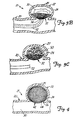
- FIG. 6 shows the embolic agent 69 packed within the spherical device 62.
- the spherical device 62 provides support for the entire aneurysm wall 25 during the delivery of the embolic agent 69 and thereafter. This allows tighter packing of the embolic agent 69 with a reduced likelihood of overflow, and reduced likelihood of rupture particularly at the typically fragile dome region 70 of the aneurysm 22.
- FIG. 7 shows another occlusion device 72 constructed in accordance with the present invention.
- the device 72 includes a distal portion 74 which can be similar to the dish-like device 32 shown in FIG. 1 or in the shape of a sphere (not shown).
- the distal portion 74 preferably includes a nitinol wire frame 76 and covered with a mesh 78, or the like.
- the distal portion 74 is deployed within the aneurysm 22 and is preferably secured against the inner wall 25 of the aneurysm 22 at the neck 26.
- a proximal portion 80 includes a frame 82 attached to the frame 76 of the distal portion 74.
- the frame 82 can be covered with a mesh 84.
- the proximal portion 80 is expandable to conform to the inner wall of the parent vessel 20.
- the distal portion 74 is coated or treated with thrombogenic agents in a manner known to those skilled in the art to facilitate thrombosis within the aneurysm 22.
- the proximal portion 80 can be coated with non-thrombogenic agents which reduce the likelihood of thrombosis within the parent vessel 20.
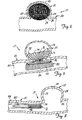
- FIG. 8 shows the preferred means of deployment of the device 72.
- the proximal portion 80 is collapsed and inserted into the distal tip 86 of a delivery catheter 88.
- the distal portion 74 may also be inserted within the delivery catheter 88 or can extend past the distal tip 86.
- the distal portion 74 is positioned with the catheter 88 to be within the aneurysm 22, and is then permitted to expand (by advancing it out of the end of catheter 88, or by application of some other suitable stimulus).
- Distal portion 74 is preferably configured so that it can be deployed from within catheter 88, retracted back into catheter 88 and redeployed.
- the proximal portion 80 is then advanced out of, and detached from, the delivery catheter 88.
- this detachment can be accomplished by any suitable system such as electrolytic detachment from a delivery member or catheter in the same fashion as a GDC coil. Delivery catheter 88 is then removed from the vascular region 21 to allow the proximal portion 80 to expand and conform to the shape of the inner wall 25 of the parent vessel 20.
- FIG. 9 shows a view of another occlusion device 92 constructed in accordance with the present invention and deployed within the aneurysm 22.
- Device 92 is formed in the shape of a parabolic dish and is characterized by a plurality of struts 94, or frame, and is covered by a mesh 96 similar to that of the device 32 shown in FIG. 1.
- the device 92 includes a small valve 98, such as a mitervalve, attached to the frame 94 at the center 100 of the dish.
- FIG. 10 shows a top view of the device 92 of FIG. 9.
- Nitinol struts 94 extend from the mitervalve 98 to form a generally circular shape.
- the mesh 96 does not cover the mitervalve 98.
- FIGS. 11A-11D show the deployment of the device 92 in accordance with the present invention.
- FIG. 11A shows the collapsed device 92 attached to the distal tip 102 of a catheter 104. The distal tip 102 of the catheter 104 is inserted through the mitervalve 98. An embolic agent 106 is contained within the catheter 104 for injection therethrough.
- FIG. 11B shows the collapsed device 92 positioned within the aneurysm 22. Once within the aneurysm 22, the device 92 is allowed to expand.
- FIG. 11C shows the expanded device 92 in position within the aneurysm 22.
- FIG. 11D shows the device 92 and embolic agent 106 within the aneurysm 22 with the catheter 104 removed. After the embolic agent 106 is deployed, gentle traction of the catheter 104 disengages the distal tip 102 from the mitervalve 98 which allows removal of catheter 104.
- other suitable detachment techniques can be used including electrolytic detachment.
- VEGF vascular endothelial growth factor
- PDGF platelet derived growth factor
- VPF vascular permeability growth factor
- bFGF basic fibroblast growth factor
- TGF-beta transforming growth factor beta
Landscapes
- Health & Medical Sciences (AREA)
- Surgery (AREA)
- Life Sciences & Earth Sciences (AREA)
- Medical Informatics (AREA)
- Animal Behavior & Ethology (AREA)
- Vascular Medicine (AREA)
- Reproductive Health (AREA)
- Engineering & Computer Science (AREA)
- Biomedical Technology (AREA)
- Heart & Thoracic Surgery (AREA)
- Veterinary Medicine (AREA)
- Molecular Biology (AREA)
- Nuclear Medicine, Radiotherapy & Molecular Imaging (AREA)
- General Health & Medical Sciences (AREA)
- Public Health (AREA)
- Neurosurgery (AREA)
- Surgical Instruments (AREA)
- Acyclic And Carbocyclic Compounds In Medicinal Compositions (AREA)
- Medicines Containing Antibodies Or Antigens For Use As Internal Diagnostic Agents (AREA)
- Prostheses (AREA)
Abstract
Description
- The present invention deals with a system for treating an aneurysm. More specifically, the present invention is directed to an occlusion system for deployment of an occlusion device within the aneurysm.
- An aneurysm is a localized stretching or distension of an artery due to a weakening of the vessel wall. For example, congenital "berry" aneurysms, i.e., small spherical distensions, occur in the vessels of the brain. The distensions -- often referred to as the aneurysm sac -- are related to defects in the muscular coating of the artery and are probably developmental in origin. Rupture of aneurysms account for the majority of spontaneous hemorrhages. Approximately 25,000 intracranial aneurysms rupture every year in North America.
- Several methods of treating aneurysms have been attempted, with varying degrees of success. At present, the treatment of aneurysms with drugs is substantially ineffective. Also, extra-vascular surgery, referred to as open craniotomy, for the purpose of preserving the parent artery is replete with disadvantages. A patient subject to open craniotomy for intercranial aneurysms typically must undergo general anesthesia, surgical removal of part of the skull, brain retraction, dissection around the neck of the sac, and placement of a clip on the parent artery to prevent rebleeding.
- Alternative treatments include endovascular occlusion where the interior of the aneurysm is entered with a guidewire or a microcatheter. An occlusion is formed within the sac with an intention to preserve the parent artery. A preferred means for forming a mass is through the introduction of an embolic agent within the sac. Examples of embolic agents include a detachable coil, which is detached from the end of a guidewire, and a liquid polymer which polymerizes rapidly on contact with blood to form a firm mass. The embolic agent may initially generate a thrombotic mass in the sac as well. The thrombotic mass is composed of the elements of blood, namely platelets, fibrin, red cells and leukocytes. However, the thrombotic mass may typically dissipate through the normal lysing process.
- Endovascular occlusion is not without drawbacks. For example, there is a risk of overfilling the sac and consequent embolic agent migration into the parent vessel. This results in occlusion of the parent artery and could lead to distal embolization. Further, there is a risk of the embolic agent becoming dislodged from hemodynamic forces, which can result in distal embolization, restricted blood flow in the parent artery or total occlusion of the parent artery.
- Moreover, endovascular occlusion can be ineffective when the neck of an aneurysm is not well defined because the risk of embolic agent migration is greater with such a sac. Prior art methods used to reduce the risk of embolic agent migration in an ill-defined neck include blockage of the parent artery with a device inside the vasculature to isolate the sac from circulation while the occlusion is formed. However, blockage of the parent artery can itself be highly undesirable, but necessary in certain circumstances when the aneurysm presents a greater risk to the patient. After the occlusion is formed in the cavity, and circulation is restored in the parent artery, an ill-defined neck increases the risk of the embolic agent becoming dislodged.
- International patent application no. WO-A-97/26939 describes an aneurysm occlusion device and represents prior art within the meaning of Rule 29 (1)(a)EPC.
- A first aspect of the present invention provides a device for treating an aneurysm in a parent vessel according to claim 1. The device preferably includes a collapsible member which is permeable to blood flow.
- A second aspect of the present invention provides a system for treating an aneurysm in a vessel according to claim 12.
-
- FIG. 1 is a side view of an occlusion device deployed within an aneurysm.
- FIGS. 2A - 2D show the deployment of the occlusion device of FIG. 1 within the aneurysm.
- FIGS. 3A - 3C show the deployment of an embolic agent in cooperation with the device of FIG. 1 within the aneurysm.
- FIG. 4 is a side view of another occlusion device deployed within an aneurysm.
- FIGS. 5A - 5C show the deployment of the occlusion device of FIG. 4.
- FIG. 6 shows the occlusion device of FIG. 4 in cooperation with an embolic agent within the aneurysm.
- FIG. 7 is a side view of another occlusion device deployed within the aneurysm.
- FIG. 8 shows the deployment of the device of FIG. 7.
- FIG. 9 is a side view of another occlusion device deployed within an aneurysm.
- FIG. 10 is a top view of the device of FIG. 9.
- FIGS. 11A-11D illustrate the deployment of the device in FIG. 9.
- FIG. 1 shows
parent vessel 20 sectioned for clarity within avascular region 21 of the body. Thevessel 20 has ananeurysm 22 with asac 24,inner wall 25 andneck 26. Thesac 24 forms avascular cavity 28 in communication with thelumen 30 ofvessel 20.Occlusion device 32, embodying the present invention, is deployed in thevascular cavity 28 proximate theneck 26. - The
device 32 is preferably a flexible structure capable of bridging theneck 26 from within theaneurysm 22. In the illustrated embodiment,device 32 does not interfere with thelumen 30 ofparent vessel 20. Thedevice 32 is formed in the shape of a dish, and includes a plurality ofstruts 36 which project radially from thecentre 38. Thedevice 32 also includes a plurality of parabolic rings 40 which lend stability to the structure. Thestruts 36 may be formed of any suitable material, but in the preferred embodiment are formed from metal and covered with fabric. Rather than rings of fabric, the struts may be covered with a mesh, not shown. Alternatively, thedevice 32 may be formed of a polymeric or similar material. -
Device 32 can be deployed in theaneurysm 22 in a variety of ways. FIGS. 2A - 2D show the deployment ofdevice 32 in accordance with the present invention. FIG. 2A showsdevice 32 collapsed and attached to thedistal end 42 ofdelivery catheter 44 insidelumen 30.Device 32 is a shape memory structure which is capable of residing in a collapsed state but then expands to its dish-like state in response to an appropriate stimulus. Thedevice 32 can be made of thermo-sensitive material which is flexible below a transition temperature and readily collapsible, but which is less resilient or generally rigid above the transition temperature. In the preferred embodiment, thestruts 36 may be formed of small diameter nitinol wire which has the shape memory properties described above. - As indicated in FIG. 2A, the
device 32 is collapsed and delivered through thevasculature 21 in a more flexible state, below its transition temperature. FIG. 2B shows thecollapsed device 32 within theaneurysm 22 and positioned there with thedelivery catheter 44. Thedelivery catheter 44 can be used to manipulate and adjust the position ofdevice 32 within theaneurysm 22 before and/or after it is expanded. - Once in place within the
aneurysm 22, the temperature of the vascular region is raised from a point below the transition temperature to a point above the transition temperature. This can be accomplished, for instance, by injecting warm saline or the like into the vascular region, or simply by letting theocclusion device 32 warm to body temperature. Also,device 32 can be delivered while being flushed with a cold saline solution to maintain the temperature ofdevice 32 below its transition temperature. Oncedevice 32 is in place, the cold saline flush is discontinued anddevice 32 warms to a temperature above the transition temperature. After theocclusion device 32 reaches the transition temperature, it expands to the predetermined diameter or width and makes contact with theinner walls 25 and theneck 26. - FIG. 2C shows the
device 32 expanded to bridgeneck 26 of theaneurysm 22. Thedelivery catheter 44 is then detached from thedevice 32 which remains in place within theaneurysm 22. Detachment can be accomplished in any number of suitable ways. For instance,device 32 can be attached with a soluble adhesive and detached by injecting a suitable solvent. Also,device 32 can be attached by a frictional fit and detached by exerting a force oncatheter 44. Further,device 32 can be detached electrolytically in the same fashion as a Guglielmi detachable coil (GDC). FIG. 2D showsdevice 32 permanently in position within theaneurysm 22 with thedelivery catheter 44 removed. -
Device 32 can also be formed of a resilient material which is permanently biased in the deployed position. In order to collapsedevice 32 for introduction into the vasculature, a filament or other fibrous thread can be removably wound about the exterior ofdevice 32 maintaining it in a collapsed position. Oncedevice 32 is introduced intocavity 28, the thread is removed, allowingdevice 32 to deploy outwardly. Removal of the thread is preferably accomplished by exerting gentle traction on the thread which causes it to disengage fromdevice 32. - FIGS. 3A-3C show the delivery of an
embolic agent 50 through the device to form a thrombotic mass within theaneurysm 22. FIG. 3A shows amicrocatheter 52 having theembolic agent 50 at thedistal tip 54 of thecatheter 52. Theembolic agent 50, such as a stainless steel coil or a liquid polymer, or a combination of solid and liquid embolic agents (e.g., a coil and a liquid polymer) is delivered to the aneurysm via the microcatheter. FIG. 3B shows the injection of theembolic agent 50 within theaneurysm 22.Distal tip 54 is positioned against thedevice 32 such that theembolic agent 50 extends into thecavity 28.Distal tip 54 anddevice 32 preferably include markings thereon such that they can be viewed during the procedure using conventional fluoroscopy, x-ray or ultrasound, or other suitable techniques, ordevice 32 anddistal tip 54 are viewed with the aid of a suitable scope or fiber optic bundle. - The permeable nature of the
device 32 allows the distal tip ofdelivery catheter 52 to be positioned behinddevice 32 incavity 28. Thedelivery catheter 52 is movable relative todevice 32 to allow precise placement of the distal tip of the catheter within thecavity 28. Catheter tip placement influences the quality of filling, and the adjustable nature improves the ability to fill theaneurysm 22. As theembolic agent 50 is injected into thecavity 28, the blood within theaneurysm 22 escapes through theneck 26 and through the holes indevice 32. As theembolic agent 50 fillscavity 28, it acts to further secure thedevice 32 in place in theneck 26. It is to be understood that theembolic agent 50 may be deployed either prior to detachment of thedelivery catheter 44 or after detachment. - FIG. 3C shows the
embolic agent 50 packed within theaneurysm 22, held in place with theocclusion device 32, and with thedelivery catheter 52 removed. Thedevice 32 andembolic agent 50 cooperate to repair the aneurysm. Theembolic agent 50 secures thedevice 32 within thesac 24 in the region ofneck 26 and prevents thedevice 32 from being pushed further into thesac 24 by hemodynamic forces. Thedevice 32 traps theembolic agent 50, permits a tighter packing of theembolic agent 50, and reduces the likelihood of migration of theembolic agent 50 out ofaneurysm 22 intoparent vessel 20. This helps prevent distal embolization. - Also, the presence of the
device 32 at theneck 26 provides a scaffolding for tissue to grow and create a new endoluminal surface inside thevessel 20 to isolate theaneurysm 22 from the circulation of blood within thevasculature 21. Thedevice 32 may be combined with biologic materials such as collagen, fibrin, or the like, to facilitate both thrombosis and cell infiltration and fibrotic tissue growth over theneck 26 to create the new parent artery endoluminal surface. - It should be noted that
device 32 is preferably formed of a continuous structure as shown in FIGS. 1-3C. However, it can also be formed of several leaflet members connected by a hinge connection at a center portion ofdevice 32 and configured to fold out upon deployment withinaneurysm 22. - FIG. 4 shows an illustration of another
occlusion device 62 in accordance with the present invention (generally referred to as a spherical occlusion device) where like portions of thevasculature 21 are referred to by like reference numerals.Spherical occlusion device 62 is similar todevice 32 shown in FIG. 1 in that it is to be deployed within theaneurysm 22 and is generally permeable to blood flow. However, thespherical device 62 includes a collapsiblespherical mesh structure 64 that not only covers theneck 26 ofaneurysm 22 but provides stability to the entireinner wall 25 of theaneurysm 22. Thestructure 64 can be fashioned from the same materials used to makedevice 32, as described above. - FIGS. 5A-5C show the deployment of the
spherical device 62 in accordance with the present invention. FIG. 5A shows thecollapsed device 62 inserted within thedistal tip 66 of adelivery catheter 68 rather than attached thereto. FIG. 5B shows the placement of thedistal tip 66 within theaneurysm 22. Thedevice 62 is then advanced out ofcatheter 68 and into theaneurysm 22 and allowed to expand and bridge theneck 26 of theaneurysm 22. FIG. 5C shows the expandedspherical device 62 within theaneurysm 22 with thecatheter 68 removed. It is to be understood that this deployment method is suitable for other occlusion devices in accordance with the present invention and not limited to the spherical device. - After the
device 62 is expanded within theaneurysm 22, a microcatheter can be used in the fashion described above to deliver an embolic agent within the spherical device. Alternatively, the same catheter used to deliverspherical device 62 can be used to deliver the embolic agent. FIG. 6 shows theembolic agent 69 packed within thespherical device 62. Thespherical device 62 provides support for theentire aneurysm wall 25 during the delivery of theembolic agent 69 and thereafter. This allows tighter packing of theembolic agent 69 with a reduced likelihood of overflow, and reduced likelihood of rupture particularly at the typicallyfragile dome region 70 of theaneurysm 22. - FIG. 7 shows another
occlusion device 72 constructed in accordance with the present invention. Thedevice 72 includes adistal portion 74 which can be similar to the dish-like device 32 shown in FIG. 1 or in the shape of a sphere (not shown). Thedistal portion 74 preferably includes anitinol wire frame 76 and covered with amesh 78, or the like. Thedistal portion 74 is deployed within theaneurysm 22 and is preferably secured against theinner wall 25 of theaneurysm 22 at theneck 26. Aproximal portion 80 includes aframe 82 attached to theframe 76 of thedistal portion 74. Theframe 82 can be covered with amesh 84. Preferably, theproximal portion 80 is expandable to conform to the inner wall of theparent vessel 20. In one preferred embodiment, thedistal portion 74 is coated or treated with thrombogenic agents in a manner known to those skilled in the art to facilitate thrombosis within theaneurysm 22. Theproximal portion 80, on the other hand, can be coated with non-thrombogenic agents which reduce the likelihood of thrombosis within theparent vessel 20. Once seated in theneck 26 ofaneurysm 22, thedistal portion 74 inhibits the migration of thedevice 72 into theparent vessel 20. Theproximal portion 80 inhibits the migration of thedevice 72 into theaneurysm sac 24. - FIG. 8 shows the preferred means of deployment of the
device 72. Theproximal portion 80 is collapsed and inserted into thedistal tip 86 of a delivery catheter 88. Thedistal portion 74 may also be inserted within the delivery catheter 88 or can extend past thedistal tip 86. During deployment, thedistal portion 74 is positioned with the catheter 88 to be within theaneurysm 22, and is then permitted to expand (by advancing it out of the end of catheter 88, or by application of some other suitable stimulus).Distal portion 74 is preferably configured so that it can be deployed from within catheter 88, retracted back into catheter 88 and redeployed. Theproximal portion 80 is then advanced out of, and detached from, the delivery catheter 88. Again, this detachment can be accomplished by any suitable system such as electrolytic detachment from a delivery member or catheter in the same fashion as a GDC coil. Delivery catheter 88 is then removed from thevascular region 21 to allow theproximal portion 80 to expand and conform to the shape of theinner wall 25 of theparent vessel 20. - FIG. 9 shows a view of another
occlusion device 92 constructed in accordance with the present invention and deployed within theaneurysm 22.Device 92 is formed in the shape of a parabolic dish and is characterized by a plurality ofstruts 94, or frame, and is covered by amesh 96 similar to that of thedevice 32 shown in FIG. 1. However, thedevice 92 includes asmall valve 98, such as a mitervalve, attached to theframe 94 at thecenter 100 of the dish. - FIG. 10 shows a top view of the
device 92 of FIG. 9. Nitinol struts 94 extend from themitervalve 98 to form a generally circular shape. Preferably, themesh 96 does not cover themitervalve 98. - FIGS. 11A-11D show the deployment of the
device 92 in accordance with the present invention. FIG. 11A shows thecollapsed device 92 attached to thedistal tip 102 of acatheter 104. Thedistal tip 102 of thecatheter 104 is inserted through themitervalve 98. Anembolic agent 106 is contained within thecatheter 104 for injection therethrough. FIG. 11B shows thecollapsed device 92 positioned within theaneurysm 22. Once within theaneurysm 22, thedevice 92 is allowed to expand. FIG. 11C shows the expandeddevice 92 in position within theaneurysm 22. Once thedevice 92 is expanded to bridge theneck 26 of theaneurysm 22, theembolic agent 106 is injected into theaneurysm 22 through themitervalve 98. FIG. 11D shows thedevice 92 andembolic agent 106 within theaneurysm 22 with thecatheter 104 removed. After theembolic agent 106 is deployed, gentle traction of thecatheter 104 disengages thedistal tip 102 from themitervalve 98 which allows removal ofcatheter 104. As with the other embodiments, other suitable detachment techniques can be used including electrolytic detachment. - It should be noted that the devices described herein can be coated with a number of suitable coatings. Among the coatings which could be applied are growth factors. A number of suitable growth factors include vascular endothelial growth factor (VEGF), platelet derived growth factor (PDGF), vascular permeability growth factor (VPF), basic fibroblast growth factor (bFGF), and transforming growth factor beta (TGF-beta).
Claims (12)
- A device (32) for treating an aneurysm (22) in a parent vessel (20), the parent vessel defining a lumen (30), the aneurysm having a neck (26) and an inner wall (25) defining a cavity (28) communicating with the lumen (30), the device (32) configured for deployment within the cavity (28) and comprising:a member (32) having a collapsed state when the device is delivered and arranged such that when the device is deployed the member (32) expands to bridge the neck (26) of the aneurysm (22) and is in contact with the inner wall (25);characterised in that the member (32) comprises either:(a) an expandable wire frame covered by a permeable mesh; or(b) an expandable frame having a covering attached thereto and a valve (98) attached to the frame (92);to allow an embolic agent (50) to be injected through the member by a microcatheter after the device is deployed to form a thrombotic mass within the aneurysm (22).
- The device of claim 1 wherein the member (32) is permeable to blood flow.
- The device of claim 1 wherein the expandable frame includes a plurality of generally parabolic wire struts (36) configured in the shape of a dish (32).
- The device of claim 1 wherein the expandable frame includes a plurality of struts (64) configured in the shape of a sphere (62).
- The device of claim 1 wherein the member further comprises a proximal portion (80) having a proximal expandable frame (82) attached to the expandable frame (76), the proximal expandable frame (82) configured for deployment within the lumen.
- The device of claim 5 wherein the distal expandable frame (76) includes a plurality of parabolic struts configured in the shape of a dish.
- The device of claim 6 wherein the proximal expandable frame (82) is expandable to contact the parent vessel (20).
- The device of claim 7 wherein the proximal expandable frame (82) is coated with a non-thromobogenic agent.
- The device of claim 1 wherein the expandable wire frame is made from a shape-memory material.
- The device of claim 1 wherein member (32) is coated with a thrombogenic agent.
- The device of claim 1 wherein the member (32) has a covering layer thereon formed of a vascular growth factor.
- A system for treating an aneurysm (22) in a vessel (20), the aneurysm (22) having an inner wall (25) and a neck (26) defining a cavity (28), the system comprising:a collapsible member (32) attached to a delivery catheter (44);wherein the collapsible member (32) is configured to be endovascularly delivered to the aneurysm (22) for deployment therein;
wherein the collapsible member (32) is expandable within the cavity (28) so as to bridge the neck (26) and contact the inner wall (25);
characterised in that the system includes a microcatheter (52) configured to have an embolic agent (50), to be positioned against said collapsible member (32), and to inject said embolic agent (50) through said collapsible member (32) into the cavity (28) to form a mass, and in that the collapsible member (32) comprises either:(a) an expandable wire frame covered by a permeable mesh; or(b) an expandable frame having a covering attached thereto and a valve (98) attached to the frame (92);to allow the embolic agent (50) to be injected through the member (32) by the microcatheter after the device is deployed.
Applications Claiming Priority (3)
| Application Number | Priority Date | Filing Date | Title |
|---|---|---|---|
| US5481097P | 1997-08-04 | 1997-08-04 | |
| US54810P | 1997-08-04 | ||
| PCT/US1998/015690 WO1999005977A1 (en) | 1997-08-04 | 1998-07-29 | Occlusion system for aneurysm repair |
Publications (2)
| Publication Number | Publication Date |
|---|---|
| EP1006890A1 EP1006890A1 (en) | 2000-06-14 |
| EP1006890B1 true EP1006890B1 (en) | 2006-09-20 |
Family
ID=21993668
Family Applications (1)
| Application Number | Title | Priority Date | Filing Date |
|---|---|---|---|
| EP98937238A Expired - Lifetime EP1006890B1 (en) | 1997-08-04 | 1998-07-29 | Occlusion system for aneurysm repair |
Country Status (8)
| Country | Link |
|---|---|
| EP (1) | EP1006890B1 (en) |
| JP (1) | JP4060528B2 (en) |
| AT (1) | ATE339919T1 (en) |
| AU (1) | AU8599898A (en) |
| CA (1) | CA2298637A1 (en) |
| DE (1) | DE69835958T2 (en) |
| ES (1) | ES2272007T3 (en) |
| WO (1) | WO1999005977A1 (en) |
Cited By (2)
| Publication number | Priority date | Publication date | Assignee | Title |
|---|---|---|---|---|
| DE102013106031A1 (en) | 2013-06-11 | 2014-12-11 | Acandis Gmbh & Co. Kg | Medical implant and system with such an implant |
| US9592068B2 (en) | 2013-03-15 | 2017-03-14 | Insera Therapeutics, Inc. | Free end vascular treatment systems |
Families Citing this family (188)
| Publication number | Priority date | Publication date | Assignee | Title |
|---|---|---|---|---|
| US6168615B1 (en) * | 1998-05-04 | 2001-01-02 | Micrus Corporation | Method and apparatus for occlusion and reinforcement of aneurysms |
| US5935148A (en) * | 1998-06-24 | 1999-08-10 | Target Therapeutics, Inc. | Detachable, varying flexibility, aneurysm neck bridge |
| US7410482B2 (en) | 1998-09-04 | 2008-08-12 | Boston Scientific-Scimed, Inc. | Detachable aneurysm neck bridge |
| AU5905599A (en) | 1998-09-04 | 2000-03-27 | Boston Scientific Limited | Detachable aneurysm neck closure patch |
| US7044134B2 (en) | 1999-11-08 | 2006-05-16 | Ev3 Sunnyvale, Inc | Method of implanting a device in the left atrial appendage |
| US6723112B2 (en) * | 1998-11-10 | 2004-04-20 | Scimed Life Systems, Inc. | Bioactive three loop coil |
| US8016852B2 (en) | 1998-11-10 | 2011-09-13 | Stryker Corporation | Bioactive components for incorporation with vaso-occlusive members |
| US6569179B2 (en) | 1998-11-10 | 2003-05-27 | Scimed Life Systems, Inc. | Bioactive three loop coil |
| US6375668B1 (en) | 1999-06-02 | 2002-04-23 | Hanson S. Gifford | Devices and methods for treating vascular malformations |
| US20020169473A1 (en) | 1999-06-02 | 2002-11-14 | Concentric Medical, Inc. | Devices and methods for treating vascular malformations |
| US6663607B2 (en) | 1999-07-12 | 2003-12-16 | Scimed Life Systems, Inc. | Bioactive aneurysm closure device assembly and kit |
| ES2283316T3 (en) * | 1999-09-13 | 2007-11-01 | Rex Medical, Lp | VASCULAR CLOSURE |
| US7662161B2 (en) | 1999-09-13 | 2010-02-16 | Rex Medical, L.P | Vascular hole closure device |
| US6231561B1 (en) | 1999-09-20 | 2001-05-15 | Appriva Medical, Inc. | Method and apparatus for closing a body lumen |
| AU2004226914B2 (en) * | 1999-10-27 | 2006-03-16 | Atritech, Inc. | Barrier Device for Ostium of Left Atrial Appendage |
| US6551303B1 (en) * | 1999-10-27 | 2003-04-22 | Atritech, Inc. | Barrier device for ostium of left atrial appendage |
| US6652555B1 (en) * | 1999-10-27 | 2003-11-25 | Atritech, Inc. | Barrier device for covering the ostium of left atrial appendage |
| US6689150B1 (en) * | 1999-10-27 | 2004-02-10 | Atritech, Inc. | Filter apparatus for ostium of left atrial appendage |
| US6350270B1 (en) | 2000-01-24 | 2002-02-26 | Scimed Life Systems, Inc. | Aneurysm liner |
| US8298257B2 (en) | 2000-06-29 | 2012-10-30 | Concentric Medical, Inc. | Systems, methods and devices for removing obstructions from a blood vessel |
| US6730104B1 (en) | 2000-06-29 | 2004-05-04 | Concentric Medical, Inc. | Methods and devices for removing an obstruction from a blood vessel |
| CA2431594A1 (en) * | 2000-10-24 | 2002-09-12 | Martin Dieck | Device and methods for treating vascular malformations |
| US7572288B2 (en) | 2001-07-20 | 2009-08-11 | Microvention, Inc. | Aneurysm treatment device and method of use |
| US8252040B2 (en) | 2001-07-20 | 2012-08-28 | Microvention, Inc. | Aneurysm treatment device and method of use |
| US8715312B2 (en) * | 2001-07-20 | 2014-05-06 | Microvention, Inc. | Aneurysm treatment device and method of use |
| US20030028209A1 (en) | 2001-07-31 | 2003-02-06 | Clifford Teoh | Expandable body cavity liner device |
| US6811560B2 (en) | 2001-09-20 | 2004-11-02 | Cordis Neurovascular, Inc. | Stent aneurysm embolization method and device |
| US6802851B2 (en) | 2001-09-20 | 2004-10-12 | Gordia Neurovascular, Inc. | Stent aneurysm embolization method using collapsible member and embolic coils |
| JP4429589B2 (en) | 2001-11-15 | 2010-03-10 | コーディス・ニューロバスキュラー・インコーポレイテッド | Aneurysm embolization device using an occluding member |
| US7318833B2 (en) | 2001-12-19 | 2008-01-15 | Nmt Medical, Inc. | PFO closure device with flexible thrombogenic joint and improved dislodgement resistance |
| WO2003082076A2 (en) | 2002-03-25 | 2003-10-09 | Nmt Medical, Inc. | Patent foramen ovale (pfo) closure clips |
| US7695488B2 (en) | 2002-03-27 | 2010-04-13 | Boston Scientific Scimed, Inc. | Expandable body cavity liner device |
| US20030195553A1 (en) | 2002-04-12 | 2003-10-16 | Scimed Life Systems, Inc. | System and method for retaining vaso-occlusive devices within an aneurysm |
| US7431729B2 (en) | 2002-06-05 | 2008-10-07 | Nmt Medical, Inc. | Patent foramen ovale (PFO) closure device with radial and circumferential support |
| US8075585B2 (en) | 2002-08-29 | 2011-12-13 | Stryker Corporation | Device and method for treatment of a vascular defect |
| AU2003294682A1 (en) | 2002-12-09 | 2004-06-30 | Nmt Medical, Inc. | Septal closure devices |
| US7229454B2 (en) | 2003-01-07 | 2007-06-12 | Boston Scientific Scimed, Inc. | Occlusive cinching devices and methods of use |
| US9861346B2 (en) | 2003-07-14 | 2018-01-09 | W. L. Gore & Associates, Inc. | Patent foramen ovale (PFO) closure device with linearly elongating petals |
| US8480706B2 (en) | 2003-07-14 | 2013-07-09 | W.L. Gore & Associates, Inc. | Tubular patent foramen ovale (PFO) closure device with catch system |
| WO2005006990A2 (en) | 2003-07-14 | 2005-01-27 | Nmt Medical, Inc. | Tubular patent foramen ovale (pfo) closure device with catch system |
| DE602004009598T2 (en) | 2003-09-12 | 2008-07-24 | NMT Medical, Inc., Boston | DEVICE FOR PREVENTING THE FORMATION OF THROMBAS IN THE LEFT PORTFOLIO |
| US20110208233A1 (en) * | 2004-01-22 | 2011-08-25 | Mcguckin Jr James F | Device for preventing clot migration from left atrial appendage |
| EP1737349A1 (en) | 2004-03-03 | 2007-01-03 | NMT Medical, Inc. | Delivery/recovery system for septal occluder |
| US7806846B2 (en) | 2004-03-30 | 2010-10-05 | Nmt Medical, Inc. | Restoration of flow in LAA via tubular conduit |
| US8308760B2 (en) | 2004-05-06 | 2012-11-13 | W.L. Gore & Associates, Inc. | Delivery systems and methods for PFO closure device with two anchors |
| WO2005110240A1 (en) | 2004-05-07 | 2005-11-24 | Nmt Medical, Inc. | Catching mechanisms for tubular septal occluder |
| US8628564B2 (en) | 2004-05-25 | 2014-01-14 | Covidien Lp | Methods and apparatus for luminal stenting |
| US8267985B2 (en) | 2005-05-25 | 2012-09-18 | Tyco Healthcare Group Lp | System and method for delivering and deploying an occluding device within a vessel |
| US20060206200A1 (en) | 2004-05-25 | 2006-09-14 | Chestnut Medical Technologies, Inc. | Flexible vascular occluding device |
| ES2607402T3 (en) | 2004-05-25 | 2017-03-31 | Covidien Lp | Flexible vascular occlusion device |
| KR101300437B1 (en) | 2004-05-25 | 2013-08-26 | 코비디엔 엘피 | Vascular stenting for aneurysms |
| CA2595809A1 (en) * | 2004-08-31 | 2006-03-09 | Cook Incorporated | Device for treating an aneurysm |
| EP1793744B1 (en) | 2004-09-22 | 2008-12-17 | Dendron GmbH | Medical implant |
| DE502004010411D1 (en) | 2004-09-22 | 2009-12-31 | Dendron Gmbh | DEVICE FOR IMPLANTING MICROWAVES |
| JP5225072B2 (en) | 2005-04-22 | 2013-07-03 | レックス メディカル リミテッド パートナーシップ | Left atrial appendage obturator |
| AU2005332044B2 (en) | 2005-05-25 | 2012-01-19 | Covidien Lp | System and method for delivering and deploying and occluding device within a vessel |
| WO2007006139A1 (en) * | 2005-07-12 | 2007-01-18 | Smart Biotech Inc. | Aneurysm occlusion device |
| US9259267B2 (en) | 2005-09-06 | 2016-02-16 | W.L. Gore & Associates, Inc. | Devices and methods for treating cardiac tissue |
| FR2890306B1 (en) * | 2005-09-08 | 2007-11-02 | Beatrix Jean | DEVICE FOR THE TREATMENT OF A VASCULAR POCKET |
| US7972359B2 (en) | 2005-09-16 | 2011-07-05 | Atritech, Inc. | Intracardiac cage and method of delivering same |
| US8545530B2 (en) | 2005-10-19 | 2013-10-01 | Pulsar Vascular, Inc. | Implantable aneurysm closure systems and methods |
| KR101334502B1 (en) | 2005-10-19 | 2013-12-05 | 펄사 배스큘러, 아이엔씨. | Method and systems for endovascularly clipping and repairing lumen and tissue defects |
| CN103381101B (en) * | 2005-10-19 | 2017-12-01 | 帕尔萨脉管公司 | For the method and system of clamping and repairing lumen and tissue defects in vascular |
| US20070167981A1 (en) | 2005-12-22 | 2007-07-19 | Nmt Medical, Inc. | Catch members for occluder devices |
| US9427216B2 (en) * | 2005-12-23 | 2016-08-30 | CARDINAL HEALTH SWITZERLAND 515 GmbH | Systems and methods for closing a vessel wound |
| US8152833B2 (en) | 2006-02-22 | 2012-04-10 | Tyco Healthcare Group Lp | Embolic protection systems having radiopaque filter mesh |
| US8870913B2 (en) | 2006-03-31 | 2014-10-28 | W.L. Gore & Associates, Inc. | Catch system with locking cap for patent foramen ovale (PFO) occluder |
| EP2015683B1 (en) | 2006-04-17 | 2015-12-09 | Covidien LP | System for mechanically positioning intravascular implants |
| WO2008074027A1 (en) * | 2006-12-13 | 2008-06-19 | Biomerix Corporation | Aneurysm occlusion devices |
| JP5249249B2 (en) | 2007-03-13 | 2013-07-31 | コヴィディエン リミテッド パートナーシップ | Implant including a coil and a stretch resistant member |
| US9005242B2 (en) | 2007-04-05 | 2015-04-14 | W.L. Gore & Associates, Inc. | Septal closure device with centering mechanism |
| WO2008131167A1 (en) | 2007-04-18 | 2008-10-30 | Nmt Medical, Inc. | Flexible catheter system |
| US20110022149A1 (en) | 2007-06-04 | 2011-01-27 | Cox Brian J | Methods and devices for treatment of vascular defects |
| EP2162101B1 (en) | 2007-06-25 | 2019-02-20 | MicroVention, Inc. | Self-expanding prosthesis |
| EP2166954A1 (en) | 2007-07-13 | 2010-03-31 | Rex Medical, L.P. | Vascular hole closure device |
| US8491629B2 (en) | 2008-02-15 | 2013-07-23 | Rex Medical | Vascular hole closure delivery device |
| US8920462B2 (en) | 2008-02-15 | 2014-12-30 | Rex Medical, L.P. | Vascular hole closure device |
| US20110029013A1 (en) | 2008-02-15 | 2011-02-03 | Mcguckin James F | Vascular Hole Closure Device |
| US8070772B2 (en) | 2008-02-15 | 2011-12-06 | Rex Medical, L.P. | Vascular hole closure device |
| US9226738B2 (en) | 2008-02-15 | 2016-01-05 | Rex Medical, L.P. | Vascular hole closure delivery device |
| US8920463B2 (en) | 2008-02-15 | 2014-12-30 | Rex Medical, L.P. | Vascular hole closure device |
| US20130165967A1 (en) | 2008-03-07 | 2013-06-27 | W.L. Gore & Associates, Inc. | Heart occlusion devices |
| AU2009239424B9 (en) | 2008-04-21 | 2014-10-09 | Covidien Lp | Braid-ball embolic devices and delivery systems |
| BRPI0911923B8 (en) | 2008-05-02 | 2021-06-22 | Sequent Medical Inc | device for treating a cerebral aneurysm |
| US9675482B2 (en) | 2008-05-13 | 2017-06-13 | Covidien Lp | Braid implant delivery systems |
| RU2011102994A (en) | 2008-07-22 | 2012-08-27 | Микро Терапьютикс, Инк. (Us) | VESSEL RECONSTRUCTION DEVICE |
| CN102202585B (en) | 2008-09-05 | 2014-04-02 | 帕尔萨脉管公司 | Systems and methods for supporting or occluding a physiological opening or cavity |
| US20100069948A1 (en) * | 2008-09-12 | 2010-03-18 | Micrus Endovascular Corporation | Self-expandable aneurysm filling device, system and method of placement |
| US8956389B2 (en) | 2009-06-22 | 2015-02-17 | W. L. Gore & Associates, Inc. | Sealing device and delivery system |
| US20120029556A1 (en) | 2009-06-22 | 2012-02-02 | Masters Steven J | Sealing device and delivery system |
| EP3300674A1 (en) | 2009-09-04 | 2018-04-04 | Pulsar Vascular, Inc. | Systems for enclosing an anatomical opening |
| CA2778639A1 (en) | 2009-11-05 | 2011-05-12 | Sequent Medical Inc. | Multiple layer filamentary devices or treatment of vascular defects |
| CN102791205B (en) | 2009-11-09 | 2016-02-03 | 恩福克斯神经医学股份有限公司 | Embolization device |
| CN102770091B (en) | 2010-01-28 | 2015-07-08 | 泰科保健集团有限合伙公司 | Vascular remodeling device |
| WO2011094638A1 (en) | 2010-01-28 | 2011-08-04 | Micro Therapeutics, Inc. | Vascular remodeling device |
| DE102010027106A1 (en) * | 2010-07-14 | 2012-01-19 | Siemens Aktiengesellschaft | Flow diverter for interrupting and bypassing blood flow into aneurysm of cerebral vessels in e.g. brain during aneurysm treatment, has stents, where diverter is designed so that diverter includes size and shape covering only aneurysm region |
| JP6087281B2 (en) * | 2010-09-10 | 2017-03-01 | メディナ メディカル,インコーポレイテッド | Device and method for treating vascular abnormalities |
| US8915950B2 (en) | 2010-12-06 | 2014-12-23 | Covidien Lp | Vascular remodeling device |
| US11484318B2 (en) | 2011-01-17 | 2022-11-01 | Artio Medical, Inc. | Expandable body device and method of use |
| KR102109781B1 (en) | 2011-01-17 | 2020-05-14 | 메타랙티브 메디컬, 인크. | Blockstent device and methods of use |
| CA2825774C (en) | 2011-02-11 | 2017-02-28 | Frank P. Becking | Two-stage deployment aneurysm embolization devices |
| WO2012118957A2 (en) * | 2011-03-02 | 2012-09-07 | Eskridge Joe Michael | Endovascular closure system |
| US20120245674A1 (en) | 2011-03-25 | 2012-09-27 | Tyco Healthcare Group Lp | Vascular remodeling device |
| JP2014522263A (en) | 2011-05-11 | 2014-09-04 | マイクロベンション インコーポレイテッド | Device for occluding a lumen |
| DE102011102933B4 (en) | 2011-05-31 | 2018-05-03 | Acandis Gmbh & Co. Kg | Medical implant for placement within a hollow body, in particular an aneurysm |
| DE102011102955B4 (en) | 2011-05-31 | 2018-05-03 | Acandis Gmbh & Co. Kg | Medical implant for arranging a hollow body, in particular an aneurysm, and method for producing a medical implant |
| KR102018035B1 (en) | 2011-06-03 | 2019-09-05 | 펄사 배스큘라, 아이엔씨. | Aneurysm devices with additional anchoring mechanisms and associated systems and methods |
| CA2837717C (en) | 2011-06-03 | 2019-07-09 | Pulsar Vascular, Inc. | Systems and methods for enclosing an anatomical opening, including shock absorbing aneurysm devices |
| US9770232B2 (en) | 2011-08-12 | 2017-09-26 | W. L. Gore & Associates, Inc. | Heart occlusion devices |
| WO2013049448A1 (en) | 2011-09-29 | 2013-04-04 | Covidien Lp | Vascular remodeling device |
| US9119625B2 (en) | 2011-10-05 | 2015-09-01 | Pulsar Vascular, Inc. | Devices, systems and methods for enclosing an anatomical opening |
| US9579104B2 (en) | 2011-11-30 | 2017-02-28 | Covidien Lp | Positioning and detaching implants |
| AU2012366236B2 (en) | 2012-01-17 | 2017-10-12 | Artio Medical, Inc. | Expandable body device and method of use |
| US9011480B2 (en) | 2012-01-20 | 2015-04-21 | Covidien Lp | Aneurysm treatment coils |
| JP2013154089A (en) | 2012-01-31 | 2013-08-15 | Terumo Corp | Aneurysm treatment device and aneurysm treatment method |
| US9687245B2 (en) | 2012-03-23 | 2017-06-27 | Covidien Lp | Occlusive devices and methods of use |
| US9259229B2 (en) | 2012-05-10 | 2016-02-16 | Pulsar Vascular, Inc. | Systems and methods for enclosing an anatomical opening, including coil-tipped aneurysm devices |
| US9155647B2 (en) | 2012-07-18 | 2015-10-13 | Covidien Lp | Methods and apparatus for luminal stenting |
| US9114001B2 (en) | 2012-10-30 | 2015-08-25 | Covidien Lp | Systems for attaining a predetermined porosity of a vascular device |
| US9452070B2 (en) | 2012-10-31 | 2016-09-27 | Covidien Lp | Methods and systems for increasing a density of a region of a vascular device |
| US9186267B2 (en) | 2012-10-31 | 2015-11-17 | Covidien Lp | Wing bifurcation reconstruction device |
| US9943427B2 (en) | 2012-11-06 | 2018-04-17 | Covidien Lp | Shaped occluding devices and methods of using the same |
| US9314248B2 (en) | 2012-11-06 | 2016-04-19 | Covidien Lp | Multi-pivot thrombectomy device |
| KR102309795B1 (en) | 2012-11-13 | 2021-10-08 | 코비디엔 엘피 | Occlusive devices |
| US9295571B2 (en) | 2013-01-17 | 2016-03-29 | Covidien Lp | Methods and apparatus for luminal stenting |
| US10828019B2 (en) | 2013-01-18 | 2020-11-10 | W.L. Gore & Associates, Inc. | Sealing device and delivery system |
| US9157174B2 (en) | 2013-02-05 | 2015-10-13 | Covidien Lp | Vascular device for aneurysm treatment and providing blood flow into a perforator vessel |
| US9463105B2 (en) | 2013-03-14 | 2016-10-11 | Covidien Lp | Methods and apparatus for luminal stenting |
| CN105228688B (en) | 2013-03-15 | 2019-02-19 | 伊瑟拉医疗公司 | Vascular treatment device and method |
| AU2014232323B2 (en) * | 2013-03-15 | 2019-02-14 | Artio Medical, Inc. | Expandable body device and method of use |
| US8715314B1 (en) | 2013-03-15 | 2014-05-06 | Insera Therapeutics, Inc. | Vascular treatment measurement methods |
| US8679150B1 (en) | 2013-03-15 | 2014-03-25 | Insera Therapeutics, Inc. | Shape-set textile structure based mechanical thrombectomy methods |
| CN105142545B (en) | 2013-03-15 | 2018-04-06 | 柯惠有限合伙公司 | Locking device |
| US9078658B2 (en) | 2013-08-16 | 2015-07-14 | Sequent Medical, Inc. | Filamentary devices for treatment of vascular defects |
| US9955976B2 (en) | 2013-08-16 | 2018-05-01 | Sequent Medical, Inc. | Filamentary devices for treatment of vascular defects |
| US11154302B2 (en) | 2014-03-31 | 2021-10-26 | DePuy Synthes Products, Inc. | Aneurysm occlusion device |
| US11076860B2 (en) | 2014-03-31 | 2021-08-03 | DePuy Synthes Products, Inc. | Aneurysm occlusion device |
| US9629635B2 (en) | 2014-04-14 | 2017-04-25 | Sequent Medical, Inc. | Devices for therapeutic vascular procedures |
| US9713475B2 (en) | 2014-04-18 | 2017-07-25 | Covidien Lp | Embolic medical devices |
| US9808230B2 (en) | 2014-06-06 | 2017-11-07 | W. L. Gore & Associates, Inc. | Sealing device and delivery system |
| US9814466B2 (en) | 2014-08-08 | 2017-11-14 | Covidien Lp | Electrolytic and mechanical detachment for implant delivery systems |
| CA2957601C (en) | 2014-09-17 | 2021-11-02 | Metactive Medical, Inc. | Expandable body device and method of use |
| KR102586485B1 (en) | 2015-02-25 | 2023-10-16 | 갤럭시 테라퓨틱스, 아이엔씨 | Systems and methods for treating aneurysms |
| EP3277198B1 (en) * | 2015-04-01 | 2023-10-25 | Boston Scientific Scimed, Inc. | Systems for delivery of gel embolics |
| US10478194B2 (en) | 2015-09-23 | 2019-11-19 | Covidien Lp | Occlusive devices |
| EP3416568A4 (en) | 2016-02-16 | 2019-10-16 | Insera Therapeutics, Inc. | Aspiration devices and anchored flow diverting devices |
| RU2019110988A (en) * | 2016-09-14 | 2020-10-15 | Мединол Лтд. | DEVICE FOR CLOSING ANEURISM |
| US10576099B2 (en) | 2016-10-21 | 2020-03-03 | Covidien Lp | Injectable scaffold for treatment of intracranial aneurysms and related technology |
| EP3585275A1 (en) | 2017-02-23 | 2020-01-01 | DePuy Synthes Products, Inc. | Aneurysm device and delivery system |
| US11432809B2 (en) | 2017-04-27 | 2022-09-06 | Boston Scientific Scimed, Inc. | Occlusive medical device with fabric retention barb |
| FR3070853B1 (en) * | 2017-09-10 | 2023-01-13 | Stsat Ag | SYSTEM FOR TREATING ANEURISM |
| FR3072018B1 (en) * | 2017-10-05 | 2021-11-26 | Stsat Ag | SYSTEM FOR TREATING AN ANEVRISM |
| FR3072014B1 (en) * | 2017-10-05 | 2021-11-26 | Stsat Ag | SYSTEM FOR TREATING AN ANEVRISM |
| FR3072558B1 (en) * | 2017-10-23 | 2021-11-26 | Stsat Ag | SYSTEM FOR PLUGGING AN ANEVRISM |
| US11185335B2 (en) | 2018-01-19 | 2021-11-30 | Galaxy Therapeutics Inc. | System for and method of treating aneurysms |
| US10905430B2 (en) | 2018-01-24 | 2021-02-02 | DePuy Synthes Products, Inc. | Aneurysm device and delivery system |
| EP3755276A1 (en) * | 2018-02-23 | 2020-12-30 | Neurvana Medical, LLC | Novel enhanced orb-like intrasacular device |
| US11596412B2 (en) | 2018-05-25 | 2023-03-07 | DePuy Synthes Products, Inc. | Aneurysm device and delivery system |
| US11058430B2 (en) | 2018-05-25 | 2021-07-13 | DePuy Synthes Products, Inc. | Aneurysm device and delivery system |
| US10939915B2 (en) | 2018-05-31 | 2021-03-09 | DePuy Synthes Products, Inc. | Aneurysm device and delivery system |
| US11051825B2 (en) | 2018-08-08 | 2021-07-06 | DePuy Synthes Products, Inc. | Delivery system for embolic braid |
| CN112714632A (en) | 2018-08-21 | 2021-04-27 | 波士顿科学医学有限公司 | Barbed protruding member for cardiovascular devices |
| IL269005A (en) * | 2018-09-12 | 2019-10-31 | Depuy Synthes Products Inc | Improved aneurysm occlusion device |
| US11123077B2 (en) | 2018-09-25 | 2021-09-21 | DePuy Synthes Products, Inc. | Intrasaccular device positioning and deployment system |
| US11076861B2 (en) | 2018-10-12 | 2021-08-03 | DePuy Synthes Products, Inc. | Folded aneurysm treatment device and delivery method |
| US11406392B2 (en) | 2018-12-12 | 2022-08-09 | DePuy Synthes Products, Inc. | Aneurysm occluding device for use with coagulating agents |
| US11272939B2 (en) | 2018-12-18 | 2022-03-15 | DePuy Synthes Products, Inc. | Intrasaccular flow diverter for treating cerebral aneurysms |
| US11504105B2 (en) | 2019-01-25 | 2022-11-22 | Rex Medical L.P. | Vascular hole closure device |
| US11134953B2 (en) | 2019-02-06 | 2021-10-05 | DePuy Synthes Products, Inc. | Adhesive cover occluding device for aneurysm treatment |
| CN113573650A (en) | 2019-03-15 | 2021-10-29 | 后续医疗股份有限公司 | Wire device with flexible connection for treating vascular defects |
| EP3908209A4 (en) | 2019-03-15 | 2022-10-19 | Sequent Medical, Inc. | Filamentary devices for treatment of vascular defects |
| WO2020190639A1 (en) | 2019-03-15 | 2020-09-24 | Sequent Medical, Inc. | Filamentary devices for treatment of vascular defects |
| US11337706B2 (en) | 2019-03-27 | 2022-05-24 | DePuy Synthes Products, Inc. | Aneurysm treatment device |
| US11672542B2 (en) | 2019-05-21 | 2023-06-13 | DePuy Synthes Products, Inc. | Aneurysm treatment with pushable ball segment |
| US11278292B2 (en) | 2019-05-21 | 2022-03-22 | DePuy Synthes Products, Inc. | Inverting braided aneurysm treatment system and method |
| US11602350B2 (en) | 2019-12-05 | 2023-03-14 | DePuy Synthes Products, Inc. | Intrasaccular inverting braid with highly flexible fill material |
| US11607226B2 (en) | 2019-05-21 | 2023-03-21 | DePuy Synthes Products, Inc. | Layered braided aneurysm treatment device with corrugations |
| US11413046B2 (en) | 2019-05-21 | 2022-08-16 | DePuy Synthes Products, Inc. | Layered braided aneurysm treatment device |
| US11497504B2 (en) | 2019-05-21 | 2022-11-15 | DePuy Synthes Products, Inc. | Aneurysm treatment with pushable implanted braid |
| US10653425B1 (en) | 2019-05-21 | 2020-05-19 | DePuy Synthes Products, Inc. | Layered braided aneurysm treatment device |
| US11058431B2 (en) | 2019-05-25 | 2021-07-13 | Galaxy Therapeutics, Inc. | Systems and methods for treating aneurysms |
| WO2021011694A1 (en) | 2019-07-17 | 2021-01-21 | Boston Scientific Scimed, Inc. | Left atrial appendage implant with continuous covering |
| CN114340516A (en) | 2019-08-30 | 2022-04-12 | 波士顿科学医学有限公司 | Left atrial appendage implant with sealing disk |
| CN114630627A (en) | 2019-11-04 | 2022-06-14 | 柯惠有限合伙公司 | Devices, systems, and methods for treating intracranial aneurysms |
| US11457926B2 (en) | 2019-12-18 | 2022-10-04 | DePuy Synthes Products, Inc. | Implant having an intrasaccular section and intravascular section |
| WO2021195085A1 (en) | 2020-03-24 | 2021-09-30 | Boston Scientific Scimed, Inc. | Medical system for treating a left atrial appendage |
| KR20220050060A (en) * | 2020-10-15 | 2022-04-22 | 디퍼이 신테스 프로덕츠, 인코포레이티드 | Inverting braided aneurysm treatment system and method |
| CN112656477B (en) * | 2020-12-31 | 2023-06-20 | 杭州德诺脑神经医疗科技有限公司 | Aneurysm occlusion device and microcatheter therefor |
Family Cites Families (5)
| Publication number | Priority date | Publication date | Assignee | Title |
|---|---|---|---|---|
| FR2641692A1 (en) * | 1989-01-17 | 1990-07-20 | Nippon Zeon Co | Plug for closing an opening for a medical application, and device for the closure plug making use thereof |
| AU4926193A (en) * | 1992-09-21 | 1994-04-12 | Vitaphore Corporation | Embolization plugs for blood vessels |
| ES2340142T3 (en) * | 1994-07-08 | 2010-05-31 | Ev3 Inc. | SYSTEM TO CARRY OUT AN INTRAVASCULAR PROCEDURE. |
| US5645558A (en) * | 1995-04-20 | 1997-07-08 | Medical University Of South Carolina | Anatomically shaped vasoocclusive device and method of making the same |
| US5733294A (en) * | 1996-02-28 | 1998-03-31 | B. Braun Medical, Inc. | Self expanding cardiovascular occlusion device, method of using and method of making the same |
-
1998
- 1998-07-29 AT AT98937238T patent/ATE339919T1/en not_active IP Right Cessation
- 1998-07-29 CA CA002298637A patent/CA2298637A1/en not_active Abandoned
- 1998-07-29 AU AU85998/98A patent/AU8599898A/en not_active Abandoned
- 1998-07-29 WO PCT/US1998/015690 patent/WO1999005977A1/en active IP Right Grant
- 1998-07-29 EP EP98937238A patent/EP1006890B1/en not_active Expired - Lifetime
- 1998-07-29 ES ES98937238T patent/ES2272007T3/en not_active Expired - Lifetime
- 1998-07-29 DE DE69835958T patent/DE69835958T2/en not_active Expired - Lifetime
- 1998-07-29 JP JP2000504799A patent/JP4060528B2/en not_active Expired - Fee Related
Cited By (2)
| Publication number | Priority date | Publication date | Assignee | Title |
|---|---|---|---|---|
| US9592068B2 (en) | 2013-03-15 | 2017-03-14 | Insera Therapeutics, Inc. | Free end vascular treatment systems |
| DE102013106031A1 (en) | 2013-06-11 | 2014-12-11 | Acandis Gmbh & Co. Kg | Medical implant and system with such an implant |
Also Published As
| Publication number | Publication date |
|---|---|
| ATE339919T1 (en) | 2006-10-15 |
| AU8599898A (en) | 1999-02-22 |
| EP1006890A1 (en) | 2000-06-14 |
| WO1999005977A1 (en) | 1999-02-11 |
| JP4060528B2 (en) | 2008-03-12 |
| DE69835958T2 (en) | 2007-02-15 |
| ES2272007T3 (en) | 2007-04-16 |
| CA2298637A1 (en) | 1999-02-11 |
| JP2001518320A (en) | 2001-10-16 |
| DE69835958D1 (en) | 2006-11-02 |
Similar Documents
| Publication | Publication Date | Title |
|---|---|---|
| EP1006890B1 (en) | Occlusion system for aneurysm repair | |
| US11291453B2 (en) | Filamentary devices having a flexible joint for treatment of vascular defects | |
| US20210330331A1 (en) | Aneurysm occlusion device | |
| EP2314231B1 (en) | Aneurysm treatment device | |
| US7083632B2 (en) | Aneurysm embolic device with an occlusive member | |
| US7695488B2 (en) | Expandable body cavity liner device | |
| EP1207791B1 (en) | Controlled injection of liquid embolic composition | |
| JP5976899B2 (en) | System and method for supporting or occluding a physiological opening or cavity | |
| US5951599A (en) | Occlusion system for endovascular treatment of an aneurysm | |
| US7195636B2 (en) | Aneurysm neck cover for sealing an aneurysm | |
| US20080281350A1 (en) | Aneurysm Occlusion Devices | |
| US20220249098A1 (en) | Filamentary devices for treatment of vascular defects |
Legal Events
| Date | Code | Title | Description |
|---|---|---|---|
| PUAI | Public reference made under article 153(3) epc to a published international application that has entered the european phase |
Free format text: ORIGINAL CODE: 0009012 |
|
| 17P | Request for examination filed |
Effective date: 20000117 |
|
| AK | Designated contracting states |
Kind code of ref document: A1 Designated state(s): AT BE CH CY DE DK ES FI FR GB GR IE IT LI LU MC NL PT SE |
|
| AX | Request for extension of the european patent |
Free format text: AL PAYMENT 20000117;LT PAYMENT 20000117;LV PAYMENT 20000117;MK PAYMENT 20000117;RO PAYMENT 20000117;SI PAYMENT 20000117 |
|
| 17Q | First examination report despatched |
Effective date: 20030304 |
|
| GRAP | Despatch of communication of intention to grant a patent |
Free format text: ORIGINAL CODE: EPIDOSNIGR1 |
|
| GRAS | Grant fee paid |
Free format text: ORIGINAL CODE: EPIDOSNIGR3 |
|
| GRAA | (expected) grant |
Free format text: ORIGINAL CODE: 0009210 |
|
| RAP1 | Party data changed (applicant data changed or rights of an application transferred) |
Owner name: BOSTON SCIENTIFIC LIMITED |
|
| AK | Designated contracting states |
Kind code of ref document: B1 Designated state(s): AT BE CH CY DE DK ES FI FR GB GR IE IT LI LU MC NL PT SE |
|
| AX | Request for extension of the european patent |
Extension state: AL LT LV MK RO SI |
|
| PG25 | Lapsed in a contracting state [announced via postgrant information from national office to epo] |
Ref country code: LI Free format text: LAPSE BECAUSE OF FAILURE TO SUBMIT A TRANSLATION OF THE DESCRIPTION OR TO PAY THE FEE WITHIN THE PRESCRIBED TIME-LIMIT Effective date: 20060920 Ref country code: IT Free format text: LAPSE BECAUSE OF FAILURE TO SUBMIT A TRANSLATION OF THE DESCRIPTION OR TO PAY THE FEE WITHIN THE PRE;WARNING: LAPSES OF ITALIAN PATENTS WITH EFFECTIVE DATE BEFORE 2007 MAY HAVE OCCURRED AT ANY TIME BEFORE 2007. THE CORRECT EFFECTIVE DATE MAY BE DIFFERENT FROM THE ONE RECORDED.SCRIBED TIME-LIMIT Effective date: 20060920 Ref country code: FI Free format text: LAPSE BECAUSE OF FAILURE TO SUBMIT A TRANSLATION OF THE DESCRIPTION OR TO PAY THE FEE WITHIN THE PRESCRIBED TIME-LIMIT Effective date: 20060920 Ref country code: CH Free format text: LAPSE BECAUSE OF FAILURE TO SUBMIT A TRANSLATION OF THE DESCRIPTION OR TO PAY THE FEE WITHIN THE PRESCRIBED TIME-LIMIT Effective date: 20060920 Ref country code: AT Free format text: LAPSE BECAUSE OF FAILURE TO SUBMIT A TRANSLATION OF THE DESCRIPTION OR TO PAY THE FEE WITHIN THE PRESCRIBED TIME-LIMIT Effective date: 20060920 |
|
| REG | Reference to a national code |
Ref country code: GB Ref legal event code: FG4D |
|
| REG | Reference to a national code |
Ref country code: CH Ref legal event code: EP |
|
| REG | Reference to a national code |
Ref country code: IE Ref legal event code: FG4D |
|
| REF | Corresponds to: |
Ref document number: 69835958 Country of ref document: DE Date of ref document: 20061102 Kind code of ref document: P |
|
| PG25 | Lapsed in a contracting state [announced via postgrant information from national office to epo] |
Ref country code: SE Free format text: LAPSE BECAUSE OF FAILURE TO SUBMIT A TRANSLATION OF THE DESCRIPTION OR TO PAY THE FEE WITHIN THE PRESCRIBED TIME-LIMIT Effective date: 20061220 Ref country code: DK Free format text: LAPSE BECAUSE OF FAILURE TO SUBMIT A TRANSLATION OF THE DESCRIPTION OR TO PAY THE FEE WITHIN THE PRESCRIBED TIME-LIMIT Effective date: 20061220 |
|
| LTIE | Lt: invalidation of european patent or patent extension |
Effective date: 20060920 |
|
| PG25 | Lapsed in a contracting state [announced via postgrant information from national office to epo] |
Ref country code: PT Free format text: LAPSE BECAUSE OF FAILURE TO SUBMIT A TRANSLATION OF THE DESCRIPTION OR TO PAY THE FEE WITHIN THE PRESCRIBED TIME-LIMIT Effective date: 20070312 |
|
| REG | Reference to a national code |
Ref country code: CH Ref legal event code: PL |
|
| ET | Fr: translation filed | ||
| REG | Reference to a national code |
Ref country code: ES Ref legal event code: FG2A Ref document number: 2272007 Country of ref document: ES Kind code of ref document: T3 |
|
| PLBE | No opposition filed within time limit |
Free format text: ORIGINAL CODE: 0009261 |
|
| STAA | Information on the status of an ep patent application or granted ep patent |
Free format text: STATUS: NO OPPOSITION FILED WITHIN TIME LIMIT |
|
| 26N | No opposition filed |
Effective date: 20070621 |
|
| BERE | Be: lapsed |
Owner name: *BOSTON SCIENTIFIC LTD Effective date: 20070731 |
|
| PGFP | Annual fee paid to national office [announced via postgrant information from national office to epo] |
Ref country code: NL Payment date: 20070619 Year of fee payment: 10 |
|
| PG25 | Lapsed in a contracting state [announced via postgrant information from national office to epo] |
Ref country code: MC Free format text: LAPSE BECAUSE OF NON-PAYMENT OF DUE FEES Effective date: 20070731 Ref country code: GR Free format text: LAPSE BECAUSE OF FAILURE TO SUBMIT A TRANSLATION OF THE DESCRIPTION OR TO PAY THE FEE WITHIN THE PRESCRIBED TIME-LIMIT Effective date: 20061221 |
|
| PG25 | Lapsed in a contracting state [announced via postgrant information from national office to epo] |
Ref country code: BE Free format text: LAPSE BECAUSE OF NON-PAYMENT OF DUE FEES Effective date: 20070731 |
|
| REG | Reference to a national code |
Ref country code: ES Ref legal event code: FD2A Effective date: 20070730 |
|
| PG25 | Lapsed in a contracting state [announced via postgrant information from national office to epo] |
Ref country code: ES Free format text: LAPSE BECAUSE OF NON-PAYMENT OF DUE FEES Effective date: 20070730 |
|
| NLV4 | Nl: lapsed or anulled due to non-payment of the annual fee |
Effective date: 20090201 |
|
| PG25 | Lapsed in a contracting state [announced via postgrant information from national office to epo] |
Ref country code: NL Free format text: LAPSE BECAUSE OF NON-PAYMENT OF DUE FEES Effective date: 20090201 |
|
| PG25 | Lapsed in a contracting state [announced via postgrant information from national office to epo] |
Ref country code: LU Free format text: LAPSE BECAUSE OF NON-PAYMENT OF DUE FEES Effective date: 20070729 Ref country code: CY Free format text: LAPSE BECAUSE OF FAILURE TO SUBMIT A TRANSLATION OF THE DESCRIPTION OR TO PAY THE FEE WITHIN THE PRESCRIBED TIME-LIMIT Effective date: 20060920 |
|
| PGFP | Annual fee paid to national office [announced via postgrant information from national office to epo] |
Ref country code: FR Payment date: 20110727 Year of fee payment: 14 |
|
| PGFP | Annual fee paid to national office [announced via postgrant information from national office to epo] |
Ref country code: GB Payment date: 20110727 Year of fee payment: 14 |
|
| REG | Reference to a national code |
Ref country code: GB Ref legal event code: 732E Free format text: REGISTERED BETWEEN 20121011 AND 20121017 |
|
| REG | Reference to a national code |
Ref country code: DE Ref legal event code: R082 Ref document number: 69835958 Country of ref document: DE Representative=s name: PATENTANWAELTE MOELL, BITTERICH & DR. KELLER, DE Effective date: 20121129 Ref country code: DE Ref legal event code: R081 Ref document number: 69835958 Country of ref document: DE Owner name: STRYKER NV OPERATIONS LTD., IE Free format text: FORMER OWNER: BOSTON SCIENTIFIC LTD., BARBADOS, WEST INDIES, BB Effective date: 20121129 Ref country code: DE Ref legal event code: R081 Ref document number: 69835958 Country of ref document: DE Owner name: STRYKER CORP., KALAMAZOO, US Free format text: FORMER OWNER: BOSTON SCIENTIFIC LTD., BARBADOS, WEST INDIES, BB Effective date: 20121129 Ref country code: DE Ref legal event code: R081 Ref document number: 69835958 Country of ref document: DE Owner name: STRYKER NV OPERATIONS LTD., IE Free format text: FORMER OWNER: BOSTON SCIENTIFIC LTD., BARBADOS, BB Effective date: 20121129 Ref country code: DE Ref legal event code: R081 Ref document number: 69835958 Country of ref document: DE Owner name: STRYKER CORP., US Free format text: FORMER OWNER: BOSTON SCIENTIFIC LTD., BARBADOS, BB Effective date: 20121129 |
|
| REG | Reference to a national code |
Ref country code: FR Ref legal event code: TP Owner name: STRYKER CORPORATION, US Effective date: 20130103 |
|
| GBPC | Gb: european patent ceased through non-payment of renewal fee |
Effective date: 20120729 |
|
| REG | Reference to a national code |
Ref country code: FR Ref legal event code: ST Effective date: 20130329 |
|
| PG25 | Lapsed in a contracting state [announced via postgrant information from national office to epo] |
Ref country code: FR Free format text: LAPSE BECAUSE OF NON-PAYMENT OF DUE FEES Effective date: 20120731 Ref country code: GB Free format text: LAPSE BECAUSE OF NON-PAYMENT OF DUE FEES Effective date: 20120729 |
|
| PGFP | Annual fee paid to national office [announced via postgrant information from national office to epo] |
Ref country code: IE Payment date: 20140710 Year of fee payment: 17 Ref country code: DE Payment date: 20140724 Year of fee payment: 17 |
|
| REG | Reference to a national code |
Ref country code: DE Ref legal event code: R119 Ref document number: 69835958 Country of ref document: DE |
|
| REG | Reference to a national code |
Ref country code: IE Ref legal event code: MM4A |
|
| PG25 | Lapsed in a contracting state [announced via postgrant information from national office to epo] |
Ref country code: DE Free format text: LAPSE BECAUSE OF NON-PAYMENT OF DUE FEES Effective date: 20160202 |
|
| PG25 | Lapsed in a contracting state [announced via postgrant information from national office to epo] |
Ref country code: IE Free format text: LAPSE BECAUSE OF NON-PAYMENT OF DUE FEES Effective date: 20150729 |