EP1008455A2 - Printer and method of controlling it - Google Patents
Printer and method of controlling it Download PDFInfo
- Publication number
- EP1008455A2 EP1008455A2 EP99124474A EP99124474A EP1008455A2 EP 1008455 A2 EP1008455 A2 EP 1008455A2 EP 99124474 A EP99124474 A EP 99124474A EP 99124474 A EP99124474 A EP 99124474A EP 1008455 A2 EP1008455 A2 EP 1008455A2
- Authority
- EP
- European Patent Office
- Prior art keywords
- printing medium
- printing
- printer
- data
- Prior art date
- Legal status (The legal status is an assumption and is not a legal conclusion. Google has not performed a legal analysis and makes no representation as to the accuracy of the status listed.)
- Granted
Links
Images


Classifications
-
- B—PERFORMING OPERATIONS; TRANSPORTING
- B41—PRINTING; LINING MACHINES; TYPEWRITERS; STAMPS
- B41J—TYPEWRITERS; SELECTIVE PRINTING MECHANISMS, i.e. MECHANISMS PRINTING OTHERWISE THAN FROM A FORME; CORRECTION OF TYPOGRAPHICAL ERRORS
- B41J11/00—Devices or arrangements of selective printing mechanisms, e.g. ink-jet printers or thermal printers, for supporting or handling copy material in sheet or web form
- B41J11/36—Blanking or long feeds; Feeding to a particular line, e.g. by rotation of platen or feed roller
- B41J11/42—Controlling printing material conveyance for accurate alignment of the printing material with the printhead; Print registering
-
- B—PERFORMING OPERATIONS; TRANSPORTING
- B41—PRINTING; LINING MACHINES; TYPEWRITERS; STAMPS
- B41J—TYPEWRITERS; SELECTIVE PRINTING MECHANISMS, i.e. MECHANISMS PRINTING OTHERWISE THAN FROM A FORME; CORRECTION OF TYPOGRAPHICAL ERRORS
- B41J11/00—Devices or arrangements of selective printing mechanisms, e.g. ink-jet printers or thermal printers, for supporting or handling copy material in sheet or web form
- B41J11/0095—Detecting means for copy material, e.g. for detecting or sensing presence of copy material or its leading or trailing end
-
- B—PERFORMING OPERATIONS; TRANSPORTING
- B41—PRINTING; LINING MACHINES; TYPEWRITERS; STAMPS
- B41J—TYPEWRITERS; SELECTIVE PRINTING MECHANISMS, i.e. MECHANISMS PRINTING OTHERWISE THAN FROM A FORME; CORRECTION OF TYPOGRAPHICAL ERRORS
- B41J3/00—Typewriters or selective printing or marking mechanisms characterised by the purpose for which they are constructed
- B41J3/60—Typewriters or selective printing or marking mechanisms characterised by the purpose for which they are constructed for printing on both faces of the printing material
-
- B—PERFORMING OPERATIONS; TRANSPORTING
- B41—PRINTING; LINING MACHINES; TYPEWRITERS; STAMPS
- B41J—TYPEWRITERS; SELECTIVE PRINTING MECHANISMS, i.e. MECHANISMS PRINTING OTHERWISE THAN FROM A FORME; CORRECTION OF TYPOGRAPHICAL ERRORS
- B41J3/00—Typewriters or selective printing or marking mechanisms characterised by the purpose for which they are constructed
- B41J3/44—Typewriters or selective printing mechanisms having dual functions or combined with, or coupled to, apparatus performing other functions
Definitions
- the present invention relates to a printer for printing on cut-sheet type printing media.
- the invention further relates to a method of controlling the printer. More particularly, the present invention relates to a printer and its control method for handling a printing medium, such as a personal check, having machine-distinguishable front and back sides on which different information must be appropriately printed.
- Printers for printing on such kind of specifically formatted printing media such as invoices, tickets, and personal or corporate checks, are widely available and commonly used (these printing media will simply be referred to as "forms" hereinafter).
- Typical of such printers are point-of-sale (POS) printers for printing sales receipts as well as customer checks received for payment.
- POS point-of-sale
- a POS system basically comprises a host device and a printer connected to this host.
- the printer comprises a print head for check printing and a MICR (Magnetic Ink Character Recognition) head for reading magnetic ink characters preprinted on the check.
- MICR Magnetic Ink Character Recognition
- MICR text is printed at a standardized location on the checks.
- the MICR head passes over the MICR text, the text is detected and converted to an electrical signal.
- the waveform of the signal varies with each letter, thereby making it possible to interpret the signal to recognize and read the preprinted MICR text.
- Check processing at the POS station includes printing the date, store name, and check amount on the check's front side, and printing a check endorsement and the store's bank account number on the check's back side. For simplicity below, these operations are hereafter referred to as simply front-side printing and back-side printing.
- Fig. 19 is a flow chart of a check processing method using a conventional printer configured to read MICR text when the check is inserted for back-side printing.
- step S1901 When a store clerk receives a check for payment from a customer, the clerk performs operations informing the host that payment via check is being received. This causes the host device to start check processing, and send a MICR text read command to the printer. The printer receives and interprets this read command, and waits for the check to be inserted (step S1901).
- the printer When the clerk inserts the check into the printer, the printer reads and recognizes the MICR text (step S1902), and sends the result to the host (step S1903). The host then determines whether the check is valid based on the information received from the printer. Check validation in this example can be simply accomplished by comparing the account number read from the check with a database of invalid account numbers.
- the host sends the information for the front-side printing to the printer. Note that this information is hereafter referred to as the payment information.
- the printer receives the payment information (step S1904), it advances the check to the printing start position of the print head (step S1905), prints (step S1906), and then ejects the printed check (step S1907).
- the clerk then turns the check over and reinserts it into the printer.
- the printer again advances the check to the printing start position (step S1908).
- the host sends the information for the back-side printing, referred to as the endorsement information below, to the printer.
- the printer receives the endorsement information (step S1909), prints (step S1910), and ejects the printed check (step S1911).
- the clerk then hands the printed check to the customer for verification and signing, and receives the check back from the customer to complete the transaction.
- the order of printing on the front side and the back side of the check assumes the MICR reader and the print head to be positioned on the same side of the path the check takes through the printer. If the MICR reader and the print head were on opposite sides of that path, the host would send the endorsement information in the first step and the payment information in the second step.
- a conventional printer of this type prints on both sides of a check or other form by printing data in the sequence they are received from the host, i.e., printing a first set of information on one side of the form, waiting for the operator to reverse and reinsert the form, and then printing a second set of information on the other side of the form.
- printers While some printers have the print head and the MICR head positioned on the same side of the form transportation path, other printers have these heads on opposite sides of the form transportation path.
- the host must therefore change the sequence in which data is sent to the printer based on whether these heads are on the same or opposite sides of the path. That is, the host must be set up or switched to send either the information for front-side printing, i.e., the payment information in the above example, or the information for back-side printing, i.e., the endorsement information in the above example, first, and this further complicates the printing process.
- JP-U-3-70953/1991 discloses a printer provided with detection means for detecting the direction or orientation in which a printing medium has been inserted. The position and direction of the characters to be printed is determined in accordance with the detected direction.
- a printer with a similar function is disclosed in JP-A-61215077/1986. This known printer detects the orientation in which a form has been inserted by means of two detectors for detecting a magnetic stripe on a form to be printed.
- JP-U-2-65559/1990 discloses duplex printer including a detector for detecting whether data received from a host is for single-side printing or duplex printing. In the latter case, the data are separated into front-side data to be printed on one side and back-side data to be printed on the other side.
- the front-side data and the back-side data are stored in respective buffer memories.
- Two printing mechanisms are provided for printing the front-side data to one side of a printing medium, and printing the back-side data to the other side of the printing medium, respectively.
- JP-A-62-156790/1987 discloses a printer for printing airline tickets.
- the printer has a bar code detector to detect whether a correct form for the ticket to be printed has been inserted.
- the host device can easily control the printing process without the host device being switched or set to match a particular printer configuration.
- the printer operator can use the printer without concern for whether a form is inserted with one side facing a particular direction or whether the form is inserted with a particular edge leading through the form transportation path.
- a printer according to the present invention preferably comprises detection means for detecting the edge orientation with which a printing medium is inserted to the printer, i.e., which of the form's edges is the leading edge, and a rotation means for rotating the print data if necessary based on the detected edge orientation.
- print data can be processed depending on both the form side and the lengthwise or widthwise edge orientation of the inserted form.
- the form side and the lengthwise or widthwise edge orientation of the inserted form can be detected by detecting a specific mark on the printing medium.
- Exemplary marks include magnetic ink characters and bar codes. It is also possible to use a printing medium having one or more predetermined corners cut off. In this case the form side and the edge orientation can be detected by detecting the which corner(s) is cut off.
- the printer is controlled by means of a program controlled microprocessor.
- the control method can be provided by way of a storage medium storing a corresponding control program.
- Exemplary storage media include: semiconductor memory, CD-ROM, floppy disk, hard disk, magneto-optical disk, DVD-ROM and DVD-RAM disks, and magnetic tape. Such storage media can also be used to implement aspects of the present invention in existing printers.
- This control program can also be made available through a site on the World Wide Web, enabling users to download the program for use with existing printers.
- Fig. 1 is a sectional view of a printer according to a first embodiment of the present invention.
- This printer 10 comprises a main housing 101 having a control unit, an insertion opening 102 through which a form is inserted, an MICR reader 103, transportation rollers 104a to 104d, a print head 105 for printing on the form, a platen 106 opposite to the print head 105, and a form ejection mechanism 107 for passing the form out from the printer.
- the MICR reader 103 is disposed in proximity to the insertion opening 102 for reading MICR text preprinted on an inserted form.
- Fig. 2 is a functional block diagram of a control unit 200 of printer 10.
- control unit 200 comprises an input/output (I/O) interface 201, a data receiver 202, a data interpreter 203, a form side detector 207, a print buffer 206 for temporarily storing print data for a particular form side, a printing controller 208 for printing data stored in the print buffer 206, a data transmitter 205, and a controller 204 for controlling various parts of the printer 10.
- I/O input/output
- Control commands, print data, and other information are passed between the control unit 200 and the host 220 through the I/O interface 201.
- Control commands, print data, and other information are received through the I/O interface 201 by the data receiver 202, and the received data is then interpreted by the data interpreter 203.
- the form side detector 207 detects the form side, i.e., whether the form has been inserted with its front side or its back side facing a particular direction (simply referred to as "front-side up” and "back-side up” hereinafter even though the particular direction is not necessarily the upward direction).
- the data transmitter 205 passes the printer processing status to the host 220 via the I/O interface 201.
- Fig. 3 is a flow chart of a printing process executed by printer 10.
- the data receiver 202 receives and interprets data received from the host 220 (step S301).
- the received data includes both a print command specifying a printing process, and print data.
- the print command contains information indicative of whether the print data sent after the print command is to be printed on the front or the back side of the form. It is to be noted that a print command indicating front-side printing is hereafter referred to as front-side printing command, and a print command indicating back-side printing is hereafter referred to as back-side printing command.
- the form side detector 207 detects whether the form has been inserted front-side up or back-side up (step S303).
- the inserted form is advanced by a transportation mechanism comprising transportation rollers 104a and 104b to a specific position at the MICR reader 103.
- the MICR reader 103 attempts to scan the MICR text preprinted on the form front. If the MICR reader 103 successfully reads the text and captures a magnetic waveform, the magnetic waveform is sent to the form side detector 207.
- the form side detector 207 detects whether the form is front-side up or not based on whether a magnetic waveform is received from the MICR reader 103.
- the MICR reader 103 is able to read MICR text and thus capture a magnetic waveform from the form surface, the form has been inserted front-side up for printing on the front; if a magnetic waveform cannot be captured, the form has been inserted back-side up for printing on the back.
- the controller 204 performs a printing process or error handling process based on the results supplied from the data interpreter 203 and the form side detector 207.
- step S305 the print data is stored in the print buffer 206; the form is advanced to a specific position at the print head 105 by the transportation mechanism; and the printing controller 208 then drives the print head 105 to print the print data stored in the print buffer 206 on the form.
- the printing controller 208 sends a printing completed signal to the controller 204.
- the controller 204 receives this signal, it causes the data transmitter 205 to send a printing completed notice to the host 220 (step S306).
- step S304 If the form side detected by the form side detector 207 is not the same as that specified by the print command (step S304 returns NO), the controller 204 sends an insertion error notice via the data transmitter 205 to the host 220 (step S307).
- the form is then ejected (step S308) and the printing process ends once the controller 204 sends either the printing completed notice or the insertion error notice to the host 220.
- the form be ejected in different directions depending on whether the form was inserted appropriately and was successfully printed, or was incorrectly inserted and was not printed.
- the form is preferably ejected through the form ejection mechanism 107, while in the latter case, the form is preferably ejected through the insertion opening 102. In this way the operator can easily determine whether the form was printed and the printing process completed normally, or whether the form must be reinserted and to be printed.
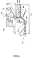
- Fig. 4 is a sectional view of a printer according to a second embodiment of the present invention.
- Printer 20 according to this second embodiment differs from printer 10 shown in Fig. 1 in that it comprises a form reversing mechanism 401 for reversing an inserted form such that front-side up becomes back-side up vice versa.
- This form reversing mechanism 401 comprises first and second reversing paths 402, 403, and gates 404 to 406 for opening and closing the openings to path 402 and path 403.
- gate 404 is operated to open the entrance to path 402.
- Gate 405 at this time blocks the entrance to path 403.
- the form is then moved into path 402 far enough that its trailing end is beyond gate 405.
- Gate 405 is then operated to open the entrance to path 403, and gate 406 is operated to open the exit from path 403.
- the form is ejected through path 403 from its position inside path 402. The front and back sides of the form are thus reversed compared to the state in which the form was inserted.
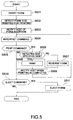
- Fig. 5 is a flow chart of an exemplary printing process executed by printer 20. Since the functional block diagram of Fig. 2 applies to printer 20 as well, the following description of Fig. 5 will also refer to Fig. 2.
- the form side detector 207 detects whether the form has been inserted front-side up or not (step S502) as described above.
- the controller 204 then causes data transmitter 205 to send a form insertion notice to the host 220 (step S503).
- the host 220 sends data to the printer 20.
- the data sent from the host 220 is received by the data receiver 202 of the printer 20 and interpreted by the data interpreter 203 (step S504).
- This data typically includes a print command for accomplishing a printing process, print data, and a form ejection command.
- the controller 204 performs a printing process as described below based on the results supplied from the data interpreter 203 and the form side detector 207.
- step S505 If the data interpreter 203 detects a print command in the data received from the host 220 (step S505 returns YES), print data contained in the data received from the host 220 is stored in the print buffer 206.
- step S506 If the form side detected by the form side detector 207 is the same as that specified by the print command (step S506 returns YES), the form is advanced to a specific position at the print head 105 by the transportation mechanism. If the form side detected by the form side detector 207 is not the same as that specified by the print command (step S506 returns NO), the form is first inverted by the form reversing mechanism 401 (step S507), and subsequently advanced to that specific position.
- the printing controller 208 then drives the print head 105 to print the print data stored in the print buffer 206 on the form (step S508).
- the printing controller 208 sends a printing completed signal to the controller 204.
- the controller 204 receives this printing completed signal, it causes the data transmitter 205 to send a printing completed notice to the host 220 (step S509).
- step S510 If the data interpreter 203 detects a form ejection command in the data received from the host 220 (step S510 returns YES), the form is ejected by the form ejection mechanism 107 (step S511).
- step S505 If the data interpreter 203 does not detect a print command (a front-side or a back-side printing command) (step S505 returns NO) and no form ejection command (step S510 returns NO) in the data received from the host 220, the printing process is terminated because a command for a process other than a printing process was received.
- a print command a front-side or a back-side printing command
- a printer according to this second embodiment of the present invention to prevent wasting print forms, improve printing efficiency, and achieve desired printing results without the host being aware of the specific printer configuration because the printer can determine whether the form side specified for printing by the print command and the side of the form inserted for printing are the same, and if they are not the same can automatically reverse the form so that the desired side of the form is presented for printing and then complete the printing process.
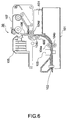
- Fig. 6 is a sectional view of a printer according to a third embodiment of the present invention.
- Printer 30 according to this third embodiment differs from printer 10 shown in Fig. 1 in that it comprises two printing mechanisms. That is, in addition to print head 105 and platen 106, printer 30 comprises a print head 601 and a platen 602. As shown in the figure, print head 105 and print head 601 are disposed on opposite sides of the form transportation path.
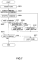
- Fig. 7 is a flow chart of an exemplary printing process executed by printer 30. It is to be noted that like steps in Fig. 5 and Fig. 7 are identified by like reference numerals, and further description thereof is omitted below. Also, since the functional block diagram of Fig. 2 applies to printer 30 as well, the following description of Fig. 7 will also refer to Fig. 2.
- step S501 to S505 When a form is inserted and a print command is received (steps S501 to S505) as described above, the controller 204 performs a printing process as described below.
- step S506 If the form side detected by the form side detector 207 is the same as that specified by the print command (step S506 returns YES), the form is advanced to a specific position at the print head 105 by the transportation mechanism. The printing controller 208 then drives the print head 105 to print the print data stored in the print buffer 206 on the form (step S701). If the form side detected by the form side detector 207 is not the same as that specified by the print command (step S506 returns NO), the form is advanced to a specific position at the print head 601. The printing controller 208 then drives the print head 601 to print the print data stored in the print buffer 206 on the form (step S702).
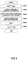
- Fig. 8 is a flow chart of an exemplary printing process according to a fourth embodiment of the invention.
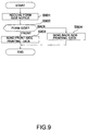
- Fig. 9 is a flow chart of the related process performed by the host. It is to be noted that the control unit and configuration of a printer for executing the process according to this fourth embodiment may be identical to those of printer 10 of the above-described first embodiment.
- the form side detector 207 detects whether the form has been inserted front-side up or not (step S802) as described above. The controller 204 then notifies the host 220 which side was detected by sending a form side notice (step S803). That is, if the form side detector 207 detects front-side up, the controller 204 sends a "front-side” notice, otherwise a "back-side” notice to the host 220.
- step S901 When the host 220 receives such form side notice from the printer 10 (step S901), it detects whether it is the front-side notice or the back-side notice (step S902). If a front-side notice is received (step S902 returns "FRONT”), the host 220 sends data for front-side printing to the printer 10 (step S903). However, if a back-side notice is received (step S902 returns "BACK”), the host 220 sends data for back-side printing to the printer 10 (step S904).
- the printer 10 thus receives from the host 220 the print data appropriate for the form side detected in step S802, and stores the received print data in print buffer 206 (step S804).
- the printing controller 208 then drives the print head 105 to print the print data stored in print buffer 206 on the form (step S805), and then ejects the form by means of the form ejection mechanism 107 (step S806).
- the host can alternatively send a form ejection command instead of sending print data, and can notify the printer of a form insertion error.
- printer and control method it is therefore possible to achieve desired printing results with a printer and control method according to this fourth embodiment of the present invention because the printer detects and informs the host which side of the inserted form is facing a particular direction, and the host then sends print data for printing on the form front or back according to the notice received from the printer. By thus requesting print data corresponding to a specific side of the printing medium, desired printing results can be achieved even when the printing buffer capacity of the printer is limited.
- Fig. 10 is a functional block diagram of a control unit 1000 of a printer according a fifth embodiment of the invention.
- This printer may be configured in the same way as printer 10 (Fig. 1) differing only with respect to the control unit.
- control unit 1000 of the printer according to this fifth embodiment differs from control unit 200 of printer 10 in that it comprises first and second data buffer 1001 and 1002 for storing print data received from the host 220 for front-side printing and those for back-side printing, respectively.
- the print buffer 206 temporarily stores print data from either data buffer 1001 or data buffer 1002.
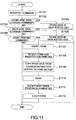
- Fig. 11 is a flow chart of a printing process executed by the printer according to this fifth embodiment.
- the data receiver 202 of the printer receives data from the host 220, and the data interpreter 203 then interprets the received data (step S1101).
- the controller 204 performs a printing process as described below based on the results supplied from the data interpreter 203.
- step S1102 If the data interpreter 203 detects a front-side data storage command (step S1102 returns YES), the controller 204 instructs the data transmitter 205 to send a request to start sending data to the host 220. When the host receives this start request, it begins sending the front-side data to the printer. The printer then stores the front-side print data received from the host 220 in data buffer 1001 (step S1103).
- step S1104 If the data interpreter 203 detects a back-side data storage command (step S1104 returns YES), the controller 204 sends a request to start sending data to the host 220. When the host receives this start request, it begins sending the back-side data to the printer. The printer then stores the back-side print data received from the host 220 in data buffer 1002 (step S1105).
- step S1106 If the data interpreter 203 detects a start printing command (step S1106 returns YES), the controller 204 is ready to start a printing process. This printing process is actually started by the form insertion (step S1107) and the form side detector 207 detecting whether the form is front-side up or back-side up (step S1108). Based on which side of the form is facing the particular direction, that is, up in this example, print data is copied from the corresponding one of the two data buffers 1001 and 1002 to the print buffer 206 (step S1109).
- the printing controller 208 then drives the print head 105 to print the print data stored in the print buffer 206 on the form (step S1110).
- the printing controller 208 sends a printing completed signal to the controller 204.
- the controller 204 receives this printing completed signal, it causes the data transmitter 205 to send a printing completed notice indicative that the inserted side has been printed to the host 220 (step S1111).
- the form is then ejected by the form ejection mechanism 107 (step S1112).
- the print data when print data is sent from the host 220 to the printer, the print data can be sent in conjunction with a data storage command.
- the data receiver 202 buffers the print data while the data interpreter 203 interprets the data storage command.
- the data receiver 202 buffers the print data while the data interpreter 203 interprets the data storage command, the received print data is stored in either data buffer 1001 or data buffer 1002, and the start printing command is then executed.
- a printer By thus storing front-side print data and back-side print data in separate buffers and detecting whether the inserted form is front-side up or back-side up, a printer according to this fifth embodiment can selectively print data stored in the data buffer corresponding to the particular form side.
- MICR text preprinted at a specific location on a form and an MICR text reader for detecting the form side The invention is not limited to MICR text for this from side detection, however, and MICR text and an MICR reader can, for example, be replaced with a bar code and bar code reader, respectively.
- the preceding embodiments include means allowing the printer for distinguishing between the front side and the back side of an inserted form.
- the form side detection is based on a particular mark, such as MICR text or a bar code, at a predetermined location on one of the form sides (the front side in the embodiments)
- a particular mark such as MICR text or a bar code
- the mark when the mark is detected, printing on that form side can be precisely positioned relative to the position of the mark.
- Printing on the opposite form side cannot be ensured to be at a particular position because the form may have been inserted with the correct side up but not with the intended edge as the leading edge.
- the preceding embodiments of the invention are particularly suitable for printing forms where the print on the back side of the form may be at a more or less arbitrary location.
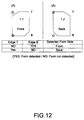
- a printing medium suitable for detecting the form side based on the form's shape has, for example, the top left and bottom right corners, as viewed on the front side of the form, cut off like the form illustrated in Fig. 12. Whether a corner is cut off or not can be detected using, for example, a photodetector. In this way it is possible to determine both the form side, i.e., whether the form is inserted front-side up or back-side up, and the edge orientation, i.e., whether the form is inserted lengthwise or widthwise or with which of its four edges as the leading edge.
- the form side detector 207 comprises a single detector disposed at position (A), that is, at a position corresponding to the left edge of an inserted form as seen in Fig. 12.
- the stars in Fig. 12 like in those in Figures 13 to 16 explained later, indicate positions fixed relative to the form where it is checked whether the form is detected or, when the position of the star corresponds to the corner of the form and that corner is cut off, not detected.
- the leading edge T of the form is detected by a form insertion detector not shown.
- the form is then advanced in the direction of arrow F by a preknown distance equal to the distance between the position of the form insertion detector and the position (A) of the form side detector.
- the form side detector either detects the form or does not detect it depending on whether the corresponding corner of the form is cut off.
- the form side detector will not detect the form at the leading edge T because the upper left corner is cut off (the upper one of the two stars will be in registration with the position (A)).
- the form will then again be advanced in the direction F until the form insertion detector detects the trailing edge B of the form and be further advanced by the preknown distance. At this moment the lower one of the two stars on the left side in Fig. 12 will be in registration with the position (A) of the form side detector. This time the form side detector detects the form since the corresponding edge is not cut off. As will be appreciated, if the form is inserted back-side up as shown on the right side of Fig. 12, the two detection results of the form side detector will be just opposite. Thus, the results of the detection can be used to detect the form side of an inserted form by referring to a table such as that shown in Fig. 12.
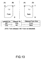
- Fig. 13 shows an alternative embodiment in which the form side detector 207 comprises two detectors at positions (A) and (B), that is, at positions corresponding to the right and the left long edge of the form. Both positions are on one line extending perpendicular to the transport direction F of the form.
- the form insertion detector detects a form, i.e., the leading edge T of the form
- the form is advanced by the above mentioned preknown distance so that the left and right corners of the leading edge are just in registration with the positions (A) and (B), respectively, of the two detectors.
- the simultaneous detection results from these two detectors allow the same conclusion as those of the two successive detection events with a single detector in Fig. 12.
- a table same as that in Fig. 12 is established for the embodiment of Fig. 13 and can be used to determine whether the form is inserted front-side up or back-side up.
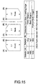
- Fig. 15 illustrates a case that differs from the one explained with reference to Fig. 13 in that only one corner of the form is cut off (the top left corner, as seen on the front side, in the example shown).
- three different detection results are possible as listed in the table shown in Fig. 15.
- this embodiment allows to determine whether the form has been inserted front-side up or back-side up, and whether the upper edge or the lower edge is the leading edge.
- Fig. 16 shows a further case differing from the case of Fig. 14 in that only one corner of the form is cut off and a third detector is provided, i.e., there are three detectors at positions (A), (B) and (C), all on the same line.
- Position (C) corresponds to the right edge of a form inserted widthwise as shown on the right side in Fig. 16.
- a set of three detection results is obtained at each of two successive detection events or measurements.
- the table shown in Fig. 16 is established and allows to determine the form side, i.e., front-side up or back-side up, and the edge orientation, i.e., which of the four edges a, b, c and d of the form is the leading edge T.
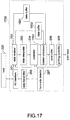
- Fig. 17 is a functional block diagram of control unit 1700 of a printer according to a sixth embodiment of the invention.
- This printer may be configured in the same way as printer 10 (Fig. 1) differing only with respect to the control unit.
- control unit 1700 comprises the two data buffers 1001 and 1002, and a rotation processor 1701.
- the form side detector in this embodiment is capable of detecting both the form side and the edge orientation of the inserted form as previously explained in conjunction with Fig. 16, for instance.
- the rotation processor 1701 reads print data from print data buffer 1001 or 1002; it then rotates the read data depending on the detected edge orientation. The rotated print data is stored in the print buffer 206 and printed.
- Fig. 18 is a flow chart of an exemplary printing process executed by the printer according to this sixth embodiment. It is to be noted that like steps in Fig. 11 and Fig. 17 are identified by like reference numeral, and further description thereof is omitted below.
- the printer of the sixth embodiment prepares for printing by means of steps S1101 to S1106 shown in Fig. 11.
- the form side detector 207 determines whether the form side is front-side up or back-side up (step S1108). Based on which side of the form is facing the particular direction, that is, up in this example, print data is copied from the appropriate data buffer 1001 or 1002 to the rotation processor 1701 (step S1801).
- the controller 204 then obtains the edge orientation of the form as detected by the form side detector 207, namely one of the orientations a, b, c, and d as shown in Fig. 16.
- step S1802 the print data in the print data rotation processor 1701 is rotated clockwise 270° (step S1803) and then sent to the print buffer 206. If the edge orientation is d (step S1804), the print data in the print data rotation processor 1701 is rotated clockwise 180° (step S1805) and then sent to the print buffer 206. If the edge orientation is b (step S1806), the print data in the print data rotation processor 1701 is rotated clockwise 90° (step S1807) and then sent to the print buffer 206. If the edge orientation is a, the print data is sent to the print buffer 206 without having been rotated (0°).
- the print buffer 206 temporarily stores the print data from the rotation processor 1701 (step S1808).
- the printing controller 208 then drives the print head 105 to print the print data stored in the print buffer 206 on the form (step S1110).
- the printing controller 208 sends a printing completed signal to the controller 204.
- the controller 204 receives this printing completed signal, it causes the data transmitter 205 to send a printing completed notice to the host 220 (step S1111).
- the printed form is then ejected by the form ejection mechanism 107 of the printer (step S1112).
- the present invention has been described in connection with the preferred embodiments thereof with reference to the accompanying drawings, it is to be noted that various changes and modifications will be apparent to those skilled in the art.
- the present invention has been described with reference to a printer in which the print head and MICR head are disposed to the same side of the form transportation path such that when a form is inserted front-side up, data is printed on the front side of the form.
- the print head and MICR head can be disposed on opposite sides of the form transportation path such that when a form is inserted front-side up, data is printed on the back side of the form.
Abstract
Description
- The present invention relates to a printer for printing on cut-sheet type printing media. The invention further relates to a method of controlling the printer. More particularly, the present invention relates to a printer and its control method for handling a printing medium, such as a personal check, having machine-distinguishable front and back sides on which different information must be appropriately printed.
- Printers for printing on such kind of specifically formatted printing media such as invoices, tickets, and personal or corporate checks, are widely available and commonly used (these printing media will simply be referred to as "forms" hereinafter). Typical of such printers are point-of-sale (POS) printers for printing sales receipts as well as customer checks received for payment. A typical check processing method used in a POS system is described below.
- A POS system basically comprises a host device and a printer connected to this host. The printer comprises a print head for check printing and a MICR (Magnetic Ink Character Recognition) head for reading magnetic ink characters preprinted on the check.
- The characters and print quality of MICR text conforms to known standards such as E13B or CMC7. MICR text is printed at a standardized location on the checks. When the MICR head passes over the MICR text, the text is detected and converted to an electrical signal. The waveform of the signal varies with each letter, thereby making it possible to interpret the signal to recognize and read the preprinted MICR text.
- Check processing at the POS station includes printing the date, store name, and check amount on the check's front side, and printing a check endorsement and the store's bank account number on the check's back side. For simplicity below, these operations are hereafter referred to as simply front-side printing and back-side printing.
- Fig. 19 is a flow chart of a check processing method using a conventional printer configured to read MICR text when the check is inserted for back-side printing.
- When a store clerk receives a check for payment from a customer, the clerk performs operations informing the host that payment via check is being received. This causes the host device to start check processing, and send a MICR text read command to the printer. The printer receives and interprets this read command, and waits for the check to be inserted (step S1901).
- When the clerk inserts the check into the printer, the printer reads and recognizes the MICR text (step S1902), and sends the result to the host (step S1903). The host then determines whether the check is valid based on the information received from the printer. Check validation in this example can be simply accomplished by comparing the account number read from the check with a database of invalid account numbers.
- If the check is determined valid, the host sends the information for the front-side printing to the printer. Note that this information is hereafter referred to as the payment information. When the printer receives the payment information (step S1904), it advances the check to the printing start position of the print head (step S1905), prints (step S1906), and then ejects the printed check (step S1907).
- The clerk then turns the check over and reinserts it into the printer. The printer again advances the check to the printing start position (step S1908). When the check is positioned, the host sends the information for the back-side printing, referred to as the endorsement information below, to the printer. The printer receives the endorsement information (step S1909), prints (step S1910), and ejects the printed check (step S1911). The clerk then hands the printed check to the customer for verification and signing, and receives the check back from the customer to complete the transaction.
- Note that the order of printing on the front side and the back side of the check assumes the MICR reader and the print head to be positioned on the same side of the path the check takes through the printer. If the MICR reader and the print head were on opposite sides of that path, the host would send the endorsement information in the first step and the payment information in the second step.
- It will thus be obvious that a conventional printer of this type prints on both sides of a check or other form by printing data in the sequence they are received from the host, i.e., printing a first set of information on one side of the form, waiting for the operator to reverse and reinsert the form, and then printing a second set of information on the other side of the form.
- Conventional printers of the type described above, however, are unable to determine whether the print data received from the host is to be printed on the front or the back of the form. The printer therefore prints whatever data it receives from the host to whichever side of the form is inserted for printing, regardless of whether this is the correct side for the data received. This means that if the form is incorrectly inserted and positioned, the printing process will nevertheless be executed. The result is a wasted form.
- Furthermore, while some printers have the print head and the MICR head positioned on the same side of the form transportation path, other printers have these heads on opposite sides of the form transportation path. The host must therefore change the sequence in which data is sent to the printer based on whether these heads are on the same or opposite sides of the path. That is, the host must be set up or switched to send either the information for front-side printing, i.e., the payment information in the above example, or the information for back-side printing, i.e., the endorsement information in the above example, first, and this further complicates the printing process.
- JP-U-3-70953/1991 discloses a printer provided with detection means for detecting the direction or orientation in which a printing medium has been inserted. The position and direction of the characters to be printed is determined in accordance with the detected direction. A printer with a similar function is disclosed in JP-A-61215077/1986. This known printer detects the orientation in which a form has been inserted by means of two detectors for detecting a magnetic stripe on a form to be printed.
- JP-U-2-65559/1990 discloses duplex printer including a detector for detecting whether data received from a host is for single-side printing or duplex printing. In the latter case, the data are separated into front-side data to be printed on one side and back-side data to be printed on the other side. The front-side data and the back-side data are stored in respective buffer memories. Two printing mechanisms are provided for printing the front-side data to one side of a printing medium, and printing the back-side data to the other side of the printing medium, respectively.
- JP-A-62-156790/1987 discloses a printer for printing airline tickets. The printer has a bar code detector to detect whether a correct form for the ticket to be printed has been inserted.
- With consideration for the above-described problems, it is an object of the present invention to provide a printer for correctly printing data on a desired side of a printing form. It is a further object of the present invention to provide a control method for this printer.
- These objects are achieved with a printer as claimed in
claim 1, a method as claimed in claim 13 and a storage medium as claimed in claim 24. - With such printer and method it is possible to determine whether the side of a form inserted for printing matches the side of the form specified by a print command. As a result, desirable printing results can be achieved and wasting printing forms as a result of printing on the wrong side of the form can be prevented. Printer throughput and efficiency can therefore be improved.
- Furthermore, the host device can easily control the printing process without the host device being switched or set to match a particular printer configuration.
- Yet further, the printer operator can use the printer without concern for whether a form is inserted with one side facing a particular direction or whether the form is inserted with a particular edge leading through the form transportation path.
- A printer according to the present invention preferably comprises detection means for detecting the edge orientation with which a printing medium is inserted to the printer, i.e., which of the form's edges is the leading edge, and a rotation means for rotating the print data if necessary based on the detected edge orientation.
- When thus comprised, print data can be processed depending on both the form side and the lengthwise or widthwise edge orientation of the inserted form.
- The form side and the lengthwise or widthwise edge orientation of the inserted form can be detected by detecting a specific mark on the printing medium. Exemplary marks include magnetic ink characters and bar codes. It is also possible to use a printing medium having one or more predetermined corners cut off. In this case the form side and the edge orientation can be detected by detecting the which corner(s) is cut off.
- Preferably, the printer is controlled by means of a program controlled microprocessor. In that case, the control method can be provided by way of a storage medium storing a corresponding control program. Exemplary storage media include: semiconductor memory, CD-ROM, floppy disk, hard disk, magneto-optical disk, DVD-ROM and DVD-RAM disks, and magnetic tape. Such storage media can also be used to implement aspects of the present invention in existing printers. This control program can also be made available through a site on the World Wide Web, enabling users to download the program for use with existing printers.
- Other objects and attainments together with a fuller understanding of the invention will become apparent and appreciated by referring to the following description of preferred embodiments taken in conjunction with the accompanying schematic drawings, in which:
- Fig. 1
- is a sectional view of a printer according to a first embodiment of the present invention;
- Fig. 2
- is a functional block diagram of the printer shown in Fig. 1;
- Fig. 3
- is a flow chart of a printing process in the printer shown in Fig. 1;
- Fig. 4
- is a sectional view of a printer according to a second embodiment of the present invention;
- Fig. 5
- is a flow chart of a printing process in the printer shown in Fig. 4;
- Fig. 6
- is a sectional view of a printer according to a third embodiment of the present invention;
- Fig. 7
- is a flow chart of a printing process in the printer shown in Fig. 6;
- Fig. 8
- is a flow chart of a printing process according to a fourth embodiment of the present invention;
- Fig. 9
- is a flow chart of a process performed by a host device during execution of the printing process according to the fourth embodiment of the present invention;
- Fig. 10
- is a functional block diagram of a printer according to a fifth embodiment of the present invention;
- Fig. 11
- is a flow chart of a printing process performed by a printer according to Fig. 10;
- Fig. 12
- and 13 are used to describe exemplary methods according to the present invention for detecting which side of a printing medium is facing a particular direction;
- Fig. 14
- to 16 are used to describe exemplary methods according to the present invention for detecting which side of a printing medium is facing a particular direction and with which edge as the leading edge the printing medium is inserted;
- Fig. 17
- is a functional block diagram of a printer according to a sixth embodiment of the present invention;
- Fig. 18
- is a flow chart of a printing process performed by a printer according to Fig. 17; and
- Fig. 19
- is a flow chart of a printing process for printing on both sides of a standardized form according to the prior art.
- Throughout the figures like reference numerals denote like parts.
- Fig. 1 is a sectional view of a printer according to a first embodiment of the present invention. This
printer 10 comprises amain housing 101 having a control unit, aninsertion opening 102 through which a form is inserted, anMICR reader 103,transportation rollers 104a to 104d, aprint head 105 for printing on the form, aplaten 106 opposite to theprint head 105, and aform ejection mechanism 107 for passing the form out from the printer. TheMICR reader 103 is disposed in proximity to theinsertion opening 102 for reading MICR text preprinted on an inserted form. - Fig. 2 is a functional block diagram of a
control unit 200 ofprinter 10. As shown in Fig. 2,control unit 200 comprises an input/output (I/O)interface 201, adata receiver 202, adata interpreter 203, aform side detector 207, aprint buffer 206 for temporarily storing print data for a particular form side, aprinting controller 208 for printing data stored in theprint buffer 206, adata transmitter 205, and acontroller 204 for controlling various parts of theprinter 10. - Control commands, print data, and other information are passed between the
control unit 200 and thehost 220 through the I/O interface 201. Control commands, print data, and other information are received through the I/O interface 201 by thedata receiver 202, and the received data is then interpreted by thedata interpreter 203. Theform side detector 207 detects the form side, i.e., whether the form has been inserted with its front side or its back side facing a particular direction (simply referred to as "front-side up" and "back-side up" hereinafter even though the particular direction is not necessarily the upward direction). Thedata transmitter 205 passes the printer processing status to thehost 220 via the I/O interface 201. - Fig. 3 is a flow chart of a printing process executed by
printer 10. At the start of the printing process thedata receiver 202 receives and interprets data received from the host 220 (step S301). The received data includes both a print command specifying a printing process, and print data. The print command contains information indicative of whether the print data sent after the print command is to be printed on the front or the back side of the form. It is to be noted that a print command indicating front-side printing is hereafter referred to as front-side printing command, and a print command indicating back-side printing is hereafter referred to as back-side printing command. - When a form is inserted into the insertion opening 102 (step S302), the
form side detector 207 detects whether the form has been inserted front-side up or back-side up (step S303). - To accomplish this front-side/back-side detection, the inserted form is advanced by a transportation mechanism comprising
transportation rollers MICR reader 103. TheMICR reader 103 then attempts to scan the MICR text preprinted on the form front. If theMICR reader 103 successfully reads the text and captures a magnetic waveform, the magnetic waveform is sent to theform side detector 207. Theform side detector 207 detects whether the form is front-side up or not based on whether a magnetic waveform is received from theMICR reader 103. That is, if theMICR reader 103 is able to read MICR text and thus capture a magnetic waveform from the form surface, the form has been inserted front-side up for printing on the front; if a magnetic waveform cannot be captured, the form has been inserted back-side up for printing on the back. - The
controller 204 performs a printing process or error handling process based on the results supplied from thedata interpreter 203 and theform side detector 207. - If the form side detected by the
form side detector 207 is the same as that specified by the print command (step S304 returns YES), the following is performed in step S305: the print data is stored in theprint buffer 206; the form is advanced to a specific position at theprint head 105 by the transportation mechanism; and theprinting controller 208 then drives theprint head 105 to print the print data stored in theprint buffer 206 on the form. When printing is completed theprinting controller 208 sends a printing completed signal to thecontroller 204. When thecontroller 204 receives this signal, it causes thedata transmitter 205 to send a printing completed notice to the host 220 (step S306). - If the form side detected by the
form side detector 207 is not the same as that specified by the print command (step S304 returns NO), thecontroller 204 sends an insertion error notice via thedata transmitter 205 to the host 220 (step S307). - The form is then ejected (step S308) and the printing process ends once the
controller 204 sends either the printing completed notice or the insertion error notice to thehost 220. It is preferable that the form be ejected in different directions depending on whether the form was inserted appropriately and was successfully printed, or was incorrectly inserted and was not printed. For example, in the former case the form is preferably ejected through theform ejection mechanism 107, while in the latter case, the form is preferably ejected through theinsertion opening 102. In this way the operator can easily determine whether the form was printed and the printing process completed normally, or whether the form must be reinserted and to be printed. - It is therefore possible by means of a printer according to this first embodiment of the present invention to achieve desired printing results without the host being aware of the specific printer configuration because the printer can determine whether the form side specified for printing by the print command and the form side inserted for printing are the same.
- It is also possible to prevent wasting printing forms because the printing is not performed when the side of the form inserted for printing does not match the side required for printing by the print command.
- Fig. 4 is a sectional view of a printer according to a second embodiment of the present invention.
Printer 20 according to this second embodiment differs fromprinter 10 shown in Fig. 1 in that it comprises aform reversing mechanism 401 for reversing an inserted form such that front-side up becomes back-side up vice versa. - This
form reversing mechanism 401 comprises first and second reversingpaths gates 404 to 406 for opening and closing the openings topath 402 andpath 403. To reverse a form,gate 404 is operated to open the entrance topath 402.Gate 405 at this time blocks the entrance topath 403. The form is then moved intopath 402 far enough that its trailing end is beyondgate 405.Gate 405 is then operated to open the entrance topath 403, andgate 406 is operated to open the exit frompath 403. After thus openinggates path 403 from its position insidepath 402. The front and back sides of the form are thus reversed compared to the state in which the form was inserted. - Fig. 5 is a flow chart of an exemplary printing process executed by
printer 20. Since the functional block diagram of Fig. 2 applies toprinter 20 as well, the following description of Fig. 5 will also refer to Fig. 2. - When a form is inserted into the insertion opening 102 (step S501), the
form side detector 207 detects whether the form has been inserted front-side up or not (step S502) as described above. Thecontroller 204 then causesdata transmitter 205 to send a form insertion notice to the host 220 (step S503). In response to this notice, thehost 220 sends data to theprinter 20. The data sent from thehost 220 is received by thedata receiver 202 of theprinter 20 and interpreted by the data interpreter 203 (step S504). This data typically includes a print command for accomplishing a printing process, print data, and a form ejection command. - The
controller 204 performs a printing process as described below based on the results supplied from thedata interpreter 203 and theform side detector 207. - If the
data interpreter 203 detects a print command in the data received from the host 220 (step S505 returns YES), print data contained in the data received from thehost 220 is stored in theprint buffer 206. - If the form side detected by the
form side detector 207 is the same as that specified by the print command (step S506 returns YES), the form is advanced to a specific position at theprint head 105 by the transportation mechanism. If the form side detected by theform side detector 207 is not the same as that specified by the print command (step S506 returns NO), the form is first inverted by the form reversing mechanism 401 (step S507), and subsequently advanced to that specific position. - The
printing controller 208 then drives theprint head 105 to print the print data stored in theprint buffer 206 on the form (step S508). When printing is completed theprinting controller 208 sends a printing completed signal to thecontroller 204. When thecontroller 204 receives this printing completed signal, it causes thedata transmitter 205 to send a printing completed notice to the host 220 (step S509). - If the
data interpreter 203 detects a form ejection command in the data received from the host 220 (step S510 returns YES), the form is ejected by the form ejection mechanism 107 (step S511). - If the
data interpreter 203 does not detect a print command (a front-side or a back-side printing command) (step S505 returns NO) and no form ejection command (step S510 returns NO) in the data received from thehost 220, the printing process is terminated because a command for a process other than a printing process was received. - It is therefore possible by means of a printer according to this second embodiment of the present invention to prevent wasting print forms, improve printing efficiency, and achieve desired printing results without the host being aware of the specific printer configuration because the printer can determine whether the form side specified for printing by the print command and the side of the form inserted for printing are the same, and if they are not the same can automatically reverse the form so that the desired side of the form is presented for printing and then complete the printing process.
- Fig. 6 is a sectional view of a printer according to a third embodiment of the present invention.
Printer 30 according to this third embodiment differs fromprinter 10 shown in Fig. 1 in that it comprises two printing mechanisms. That is, in addition toprint head 105 andplaten 106,printer 30 comprises aprint head 601 and aplaten 602. As shown in the figure,print head 105 andprint head 601 are disposed on opposite sides of the form transportation path. - Fig. 7 is a flow chart of an exemplary printing process executed by
printer 30. It is to be noted that like steps in Fig. 5 and Fig. 7 are identified by like reference numerals, and further description thereof is omitted below. Also, since the functional block diagram of Fig. 2 applies toprinter 30 as well, the following description of Fig. 7 will also refer to Fig. 2. - When a form is inserted and a print command is received (steps S501 to S505) as described above, the
controller 204 performs a printing process as described below. - If the form side detected by the
form side detector 207 is the same as that specified by the print command (step S506 returns YES), the form is advanced to a specific position at theprint head 105 by the transportation mechanism. Theprinting controller 208 then drives theprint head 105 to print the print data stored in theprint buffer 206 on the form (step S701). If the form side detected by theform side detector 207 is not the same as that specified by the print command (step S506 returns NO), the form is advanced to a specific position at theprint head 601. Theprinting controller 208 then drives theprint head 601 to print the print data stored in theprint buffer 206 on the form (step S702). - It is therefore possible by means of a printer according to this third embodiment of the present invention to prevent wasting print forms, improve printing efficiency, and achieve desired printing results without the host being aware of the specific printer configuration because the printer can automatically select which print head to use for the printing process based on which side of the form was inserted facing a particular direction.
- Fig. 8 is a flow chart of an exemplary printing process according to a fourth embodiment of the invention. Fig. 9 is a flow chart of the related process performed by the host. It is to be noted that the control unit and configuration of a printer for executing the process according to this fourth embodiment may be identical to those of
printer 10 of the above-described first embodiment. - When a form is inserted into the
insertion opening 102 of the printer 10 (step S801), theform side detector 207 detects whether the form has been inserted front-side up or not (step S802) as described above. Thecontroller 204 then notifies thehost 220 which side was detected by sending a form side notice (step S803). That is, if theform side detector 207 detects front-side up, thecontroller 204 sends a "front-side" notice, otherwise a "back-side" notice to thehost 220. - When the
host 220 receives such form side notice from the printer 10 (step S901), it detects whether it is the front-side notice or the back-side notice (step S902). If a front-side notice is received (step S902 returns "FRONT"), thehost 220 sends data for front-side printing to the printer 10 (step S903). However, if a back-side notice is received (step S902 returns "BACK"), thehost 220 sends data for back-side printing to the printer 10 (step S904). - The
printer 10 thus receives from thehost 220 the print data appropriate for the form side detected in step S802, and stores the received print data in print buffer 206 (step S804). Theprinting controller 208 then drives theprint head 105 to print the print data stored inprint buffer 206 on the form (step S805), and then ejects the form by means of the form ejection mechanism 107 (step S806). - It is to be noted that if the form side desired for printing does not match the side indicated by the form side notice from the printer, the host can alternatively send a form ejection command instead of sending print data, and can notify the printer of a form insertion error.
- It is therefore possible to achieve desired printing results with a printer and control method according to this fourth embodiment of the present invention because the printer detects and informs the host which side of the inserted form is facing a particular direction, and the host then sends print data for printing on the form front or back according to the notice received from the printer. By thus requesting print data corresponding to a specific side of the printing medium, desired printing results can be achieved even when the printing buffer capacity of the printer is limited.
- Fig. 10 is a functional block diagram of a
control unit 1000 of a printer according a fifth embodiment of the invention. This printer may be configured in the same way as printer 10 (Fig. 1) differing only with respect to the control unit. As shown in Fig. 10,control unit 1000 of the printer according to this fifth embodiment differs fromcontrol unit 200 ofprinter 10 in that it comprises first andsecond data buffer host 220 for front-side printing and those for back-side printing, respectively. Depending on whether the form is inserted front-side up or back-side up, theprint buffer 206 temporarily stores print data from eitherdata buffer 1001 ordata buffer 1002. - Fig. 11 is a flow chart of a printing process executed by the printer according to this fifth embodiment.
- The
data receiver 202 of the printer receives data from thehost 220, and thedata interpreter 203 then interprets the received data (step S1101). Thecontroller 204 performs a printing process as described below based on the results supplied from thedata interpreter 203. - If the
data interpreter 203 detects a front-side data storage command (step S1102 returns YES), thecontroller 204 instructs thedata transmitter 205 to send a request to start sending data to thehost 220. When the host receives this start request, it begins sending the front-side data to the printer. The printer then stores the front-side print data received from thehost 220 in data buffer 1001 (step S1103). - If the
data interpreter 203 detects a back-side data storage command (step S1104 returns YES), thecontroller 204 sends a request to start sending data to thehost 220. When the host receives this start request, it begins sending the back-side data to the printer. The printer then stores the back-side print data received from thehost 220 in data buffer 1002 (step S1105). - If the
data interpreter 203 detects a start printing command (step S1106 returns YES), thecontroller 204 is ready to start a printing process. This printing process is actually started by the form insertion (step S1107) and theform side detector 207 detecting whether the form is front-side up or back-side up (step S1108). Based on which side of the form is facing the particular direction, that is, up in this example, print data is copied from the corresponding one of the twodata buffers - The
printing controller 208 then drives theprint head 105 to print the print data stored in theprint buffer 206 on the form (step S1110). When printing is completed theprinting controller 208 sends a printing completed signal to thecontroller 204. When thecontroller 204 receives this printing completed signal, it causes thedata transmitter 205 to send a printing completed notice indicative that the inserted side has been printed to the host 220 (step S1111). The form is then ejected by the form ejection mechanism 107 (step S1112). - It is to be noted that when print data is sent from the
host 220 to the printer, the print data can be sent in conjunction with a data storage command. In this case thedata receiver 202 buffers the print data while thedata interpreter 203 interprets the data storage command. - It is further possible to send the storage command, the start printing command, and the print data simultaneously. In this case the
data receiver 202 buffers the print data while thedata interpreter 203 interprets the data storage command, the received print data is stored in eitherdata buffer 1001 ordata buffer 1002, and the start printing command is then executed. - By thus storing front-side print data and back-side print data in separate buffers and detecting whether the inserted form is front-side up or back-side up, a printer according to this fifth embodiment can selectively print data stored in the data buffer corresponding to the particular form side.
- Furthermore, by storing print data in the printer, steps for sending data that is printed repeatedly can be eliminated, and printer throughput and efficiency can thus be improved.
- It is to be noted that the preceding embodiments of the present invention have been described as using MICR text preprinted at a specific location on a form and an MICR text reader for detecting the form side. The invention is not limited to MICR text for this from side detection, however, and MICR text and an MICR reader can, for example, be replaced with a bar code and bar code reader, respectively.
- It is further possible to differentiate form sides based on the shape of the form using any of the exemplary methods described below.
- The preceding embodiments include means allowing the printer for distinguishing between the front side and the back side of an inserted form. Where the form side detection is based on a particular mark, such as MICR text or a bar code, at a predetermined location on one of the form sides (the front side in the embodiments), when the mark is detected, printing on that form side can be precisely positioned relative to the position of the mark. Printing on the opposite form side (the back side in the embodiments) cannot be ensured to be at a particular position because the form may have been inserted with the correct side up but not with the intended edge as the leading edge. Thus, the preceding embodiments of the invention are particularly suitable for printing forms where the print on the back side of the form may be at a more or less arbitrary location. This applies for instance to a check. While the payment information needs to be printed at prescribed positions on the front side of a check, there is no prescribed position for the endorsement information on the check's back side. In the following, embodiments will be described that detect not only the form side but also the edge orientation of an inserted form. These embodiments are, therefore, capable of positioning the print precisely both on the front side and the back side of the form.
- A printing medium suitable for detecting the form side based on the form's shape has, for example, the top left and bottom right corners, as viewed on the front side of the form, cut off like the form illustrated in Fig. 12. Whether a corner is cut off or not can be detected using, for example, a photodetector. In this way it is possible to determine both the form side, i.e., whether the form is inserted front-side up or back-side up, and the edge orientation, i.e., whether the form is inserted lengthwise or widthwise or with which of its four edges as the leading edge.
- In Fig. 12, the
form side detector 207 comprises a single detector disposed at position (A), that is, at a position corresponding to the left edge of an inserted form as seen in Fig. 12. Note that the stars in Fig. 12, like in those in Figures 13 to 16 explained later, indicate positions fixed relative to the form where it is checked whether the form is detected or, when the position of the star corresponds to the corner of the form and that corner is cut off, not detected. - In the example of Fig. 12, whenever a form is inserted into the printer the leading edge T of the form is detected by a form insertion detector not shown. The form is then advanced in the direction of arrow F by a preknown distance equal to the distance between the position of the form insertion detector and the position (A) of the form side detector. At this moment the form side detector either detects the form or does not detect it depending on whether the corresponding corner of the form is cut off. In the example in Fig. 12, if the form is inserted with the front side up, as shown on the left side in the figure, the form side detector will not detect the form at the leading edge T because the upper left corner is cut off (the upper one of the two stars will be in registration with the position (A)). The form will then again be advanced in the direction F until the form insertion detector detects the trailing edge B of the form and be further advanced by the preknown distance. At this moment the lower one of the two stars on the left side in Fig. 12 will be in registration with the position (A) of the form side detector. This time the form side detector detects the form since the corresponding edge is not cut off. As will be appreciated, if the form is inserted back-side up as shown on the right side of Fig. 12, the two detection results of the form side detector will be just opposite. Thus, the results of the detection can be used to detect the form side of an inserted form by referring to a table such as that shown in Fig. 12.
- Fig. 13 shows an alternative embodiment in which the
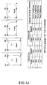
form side detector 207 comprises two detectors at positions (A) and (B), that is, at positions corresponding to the right and the left long edge of the form. Both positions are on one line extending perpendicular to the transport direction F of the form. In this case, when the form insertion detector detects a form, i.e., the leading edge T of the form, the form is advanced by the above mentioned preknown distance so that the left and right corners of the leading edge are just in registration with the positions (A) and (B), respectively, of the two detectors. The simultaneous detection results from these two detectors allow the same conclusion as those of the two successive detection events with a single detector in Fig. 12. Thus, a table same as that in Fig. 12 is established for the embodiment of Fig. 13 and can be used to determine whether the form is inserted front-side up or back-side up. - It is also possible using two detectors at positions (A) and (B) to determine both the form side and the edge orientation of the form as will be explained with reference to Fig. 14. In this case there are two successive detection events, each providing two detection results. In other words, the form is inserted and advanced in the same way as explained in conjunction with Fig. 12. Different form the case of Fig. 12, at each of the two measurement positions of the form, i.e., on the leading edge T and on the trailing edge B, there are two detection results, one from each of the two detectors (A) and (B). Compared to the case of Fig. 13, two locations at the leading edge and two locations at the trailing edge are successively brought into registration with the two respective detector positions. As will be easily understood form the explanation above, the table shown in Fig. 14 can be used to determine whether the form is inserted front-side up or back-side up and in each case whether it is inserted lengthwise or widthwise.
- Fig. 15 illustrates a case that differs from the one explained with reference to Fig. 13 in that only one corner of the form is cut off (the top left corner, as seen on the front side, in the example shown). Depending on how the form is inserted, three different detection results are possible as listed in the table shown in Fig. 15. Thus, this embodiment allows to determine whether the form has been inserted front-side up or back-side up, and whether the upper edge or the lower edge is the leading edge.
- Fig. 16 shows a further case differing from the case of Fig. 14 in that only one corner of the form is cut off and a third detector is provided, i.e., there are three detectors at positions (A), (B) and (C), all on the same line. Position (C) corresponds to the right edge of a form inserted widthwise as shown on the right side in Fig. 16. In this case, a set of three detection results is obtained at each of two successive detection events or measurements. Thus, the table shown in Fig. 16 is established and allows to determine the form side, i.e., front-side up or back-side up, and the edge orientation, i.e., which of the four edges a, b, c and d of the form is the leading edge T.
- Fig. 17 is a functional block diagram of
control unit 1700 of a printer according to a sixth embodiment of the invention. This printer may be configured in the same way as printer 10 (Fig. 1) differing only with respect to the control unit. As shown in Fig. 17, likecontrol unit 1000 of the fifth embodiment,control unit 1700 comprises the twodata buffers rotation processor 1701. The form side detector in this embodiment is capable of detecting both the form side and the edge orientation of the inserted form as previously explained in conjunction with Fig. 16, for instance. Depending on the detected form side, therotation processor 1701 reads print data fromprint data buffer print buffer 206 and printed. - Fig. 18 is a flow chart of an exemplary printing process executed by the printer according to this sixth embodiment. It is to be noted that like steps in Fig. 11 and Fig. 17 are identified by like reference numeral, and further description thereof is omitted below.
- The printer of the sixth embodiment prepares for printing by means of steps S1101 to S1106 shown in Fig. 11. When a form is inserted (step S1107), the
form side detector 207 determines whether the form side is front-side up or back-side up (step S1108). Based on which side of the form is facing the particular direction, that is, up in this example, print data is copied from theappropriate data buffer - The
controller 204 then obtains the edge orientation of the form as detected by theform side detector 207, namely one of the orientations a, b, c, and d as shown in Fig. 16. - If the edge orientation is c (step S1802), the print data in the print
data rotation processor 1701 is rotated clockwise 270° (step S1803) and then sent to theprint buffer 206. If the edge orientation is d (step S1804), the print data in the printdata rotation processor 1701 is rotated clockwise 180° (step S1805) and then sent to theprint buffer 206. If the edge orientation is b (step S1806), the print data in the printdata rotation processor 1701 is rotated clockwise 90° (step S1807) and then sent to theprint buffer 206. If the edge orientation is a, the print data is sent to theprint buffer 206 without having been rotated (0°). - The
print buffer 206 temporarily stores the print data from the rotation processor 1701 (step S1808). Theprinting controller 208 then drives theprint head 105 to print the print data stored in theprint buffer 206 on the form (step S1110). When printing is completed theprinting controller 208 sends a printing completed signal to thecontroller 204. When thecontroller 204 receives this printing completed signal, it causes thedata transmitter 205 to send a printing completed notice to the host 220 (step S1111). The printed form is then ejected by theform ejection mechanism 107 of the printer (step S1112). - It will also be obvious that while this exemplary embodiment of the invention is described as rotating by 0°, 90°, 180° or 270° to allow for four possible edge orientations, text can alternatively be rotated by other angles. Furthermore, text can be rotated clockwise as noted above, counterclockwise, or a combination of both to desirably shorten the data processing time.
- It is therefore possible by means of a printer according to this sixth embodiment of the present invention to achieve desirable printing results by storing print data for front-side printing and print data for back-side printing in separate data buffers, and rotating the print data according to the edge orientation of the inserted form.
- Although the present invention has been described in connection with the preferred embodiments thereof with reference to the accompanying drawings, it is to be noted that various changes and modifications will be apparent to those skilled in the art. For example, the present invention has been described with reference to a printer in which the print head and MICR head are disposed to the same side of the form transportation path such that when a form is inserted front-side up, data is printed on the front side of the form. It will be obvious, however, that the print head and MICR head can be disposed on opposite sides of the form transportation path such that when a form is inserted front-side up, data is printed on the back side of the form.
Claims (24)
- A printer comprising:insertion means for inserting a printing medium to be printed by the printer;connection means (201) for connecting the printer to a host device (220);receiving means (202) for receiving data via said connections means;interpreting means (203) adapted to recognize a print command and print data among the data received by said receiving means (202), to interpret the print command, and to determine that one of a front side and a back side of the printing medium that said print command indicates the print data is to be printed on;detection means (207) adapted to detect which one of said front and back sides of the printing medium is facing a predetermined direction; andcontrol means for controlling the printer, the control means comprisingcomparing means (204) adapted to compare the printing medium side determined by said interpreting means (203) with that detected by said detection means (207); andprinting means (204, 208) responsive to said comparing means (204) for printing said print data on the printing medium side detected by said detection means (207) when the printing medium sides compared by said comparing means (204) are the same.
- The printer as set forth in claim 1, wherein the control means further comprises:ejection means for ejecting a printing medium when the printing medium sides compared by said comparing means (204) are not the same.
- The printer as set forth in claim 2, wherein said insertion means comprises an insertion opening (102), the printer further comprises an ejection opening, and said control means further comprises means, responsive to said printing means having completed printing said print data, for ejecting the printing medium through said ejection opening, and responsive to said comparing means (204) for ejecting the printing medium through said insertion opening (102) when the printing medium sides compared by said comparing means (204) are not the same.
- The printer as set forth in claim 1, further comprising a reversing mechanism (401) adapted to turn an inserted printing medium from one of said front and back sides over to the other side;wherein the control means comprises means (204) responsive to said comparing means (204) for causing the reversing means (401) to turn over a printing medium to the other side when the printing medium sides compared by said comparing means are not the same, andsaid printing means (208) is responsive to said reversing means having turned over the printing medium for printing said print data on said other side of the printing medium.
- The printer as set forth in claim 1, further comprisinga first printing unit (105, 106) configured to print print data on one of said front and back sides of a printing medium, anda second printing unit (601, 602) configured to print print data on the other one of said front and back sides;wherein the control means comprises means (204) responsive to said comparing means (204) for selecting said first printing unit to print said print data on said one printing medium side when the two printing medium sides compared by said comparing means are the same, and for selecting said second printing unit to print said print data on the said other printing medium side, otherwise.
- The printer as set forth in claim 1, further comprisingsending means (205) responsive to said detection means (207) for sending via said connection means (201) a notification indicative of the printing medium side detected by the detection means (207),wherein said control means comprises means (204) responsive to said sending means having sent said notification for causing said printing means (208) to print print data received by said receiving means in response to said notification on the printing medium side detected by said detection means (207).
- The printer as set forth in claim 1, further comprising:a first data buffer (1001) configured to store print data to be printed on the front side of said printing medium, anda second data buffer (1002) configured to store print data to be printed on the back side of said printing medium;wherein said printing means (204, 208) is responsive to said detection means (207) for printing the print data stored in said first data buffer (1001) or that stored in said second data buffer (1002) when said detection means (207) detects said front side or said back side, respectively.
- The printer as set forth in any one of the preceding claims, wherein said detection means (207) is means for detecting a particular mark on the printing medium.
- The printer as set forth in claim 8, wherein said detection means (207) is a magnetic ink character reader or a bar code reader.
- The printer as set forth in any one of the preceding claims, wherein said detection means (207) includes side detection means for detecting said printing medium side, and edge detection means for detecting the edge orientation of the printing medium by detecting which of predefined edges is the leading edge of said printing medium, and said control means further comprises data rotation means (1701) responsive to said edge detection means for rotating said print data based on the detected edge orientation.
- The printer as set forth in any one of the preceding claims wherein said control means is implemented as a program controlled microprocessor
- Use of the printer as defined in claim 10 or 11 for printing on a printing medium having one or more predetermined ones of its corners cut off, wherein said side detection means (207) and said edge detection means detect the printing medium side and the edge orientation, respectively, by detecting the location of said one or more cut-off corners.
- A method of controlling a printer connected to a host device (220) so as to print on at least one of the front side and the back side of a printing medium based on data received from the host device, comprising:(a) receiving data from the host device (220);(b) recognizing print data and a print command among the data received in step (a);(c) interpreting said print command and determining that one of said front and back sides of the printing medium that said print command indicates the print data is to be printed on;(d) detecting which one of said front and back sides of a printing medium inserted into the printer is facing a particular direction;(e) comparing the printing medium side determined in step (c) with that detected in step (d); and(f) printing said print data on the printing medium side detected in step (d) when the two printing medium sides compared in step (e) are the same.
- The method as set forth in claim 13, further comprising:(g) ejecting an inserted printing medium when step (e) reveals that the two printing medium sides are not the same.
- The method as set forth in claim 14, further comprising:(h) ejecting the printing medium, following step (f), at a first location of the printer, wherein step (9) comprises ejecting the printing medium at a second location of the printer different from said first location.
- The method as set forth in claim 13, wherein step (f) comprises:(f1) turning the inserted printing medium from that one of said front and back sides detected in step (d) over to the other side if the two printing medium sides compared in step (e) are not the same; and(f2) printing said print data on said other printing medium side.
- The method as set forth in claim 13, wherein step (f) comprises:(f3) printing print data on one of said front and back sides of a printing medium, and(f4) printing print data on the other one of said front and back sides of the printing medium; and(f5) selecting step (f3) when the two printing medium sides compared in step (e) are the same, and selecting step (f4), otherwise.
- The method as set forth in claim 13, further comprising:(i) sending to the host device a notification indicative of the printing medium side detected in step (d); and(j) receiving from the host device (220) print data corresponding to the printing medium side detected in step (d).
- The method as set forth in claim 13, further comprising:(k) storing print data determined in step (c) to be printed on the front side of a printing medium in a first data buffer (1001); and(l) storing print data determined in step (c) to be printed on the back side of the printing medium in a second data buffer (1002);wherein step (f) prints, depending on the printing medium side detected in step (d), either the data stored in said first data buffer or that stored in said second data buffer.
- The method as set forth in any one of claims 13 to 19, wherein step (d) decides one or the other of said front and back sides as facing said particular direction depending on whether or not a particular mark on said printing medium is detected.
- The method as set forth in claim 20, wherein step (d) comprises detecting magnetic ink characters or a bar code as said particular mark.
- The method as set forth in any one of claims 13 to 21, further comprising(m) detecting the edge orientation of an inserted printing medium by detecting which of predefined edges is the leading edge of said printing medium, and(n) rotating said print data in accordance with the edge orientation detected in step (m).
- The method as set forth in claim 22 applied to a printing medium having one or more predetermined ones of its corners cut off, wherein step (d) detects the printing medium side and step (m) detects the edge orientation by detecting the location of said one or more cut-off corners.
- A machine readable data storage medium carrying a computer program that, when executed in a printer according to claim 11 implements a method as defined in any one of claims 13 to 23.
Priority Applications (1)
| Application Number | Priority Date | Filing Date | Title |
|---|---|---|---|
| EP07013245A EP1834798B1 (en) | 1998-12-10 | 1999-12-08 | Printer and method of controlling it |
Applications Claiming Priority (4)
| Application Number | Priority Date | Filing Date | Title |
|---|---|---|---|
| JP35175598A JP3940870B2 (en) | 1998-12-10 | 1998-12-10 | Printer device, printing method and recording medium |
| JP35175598 | 1998-12-10 | ||
| JP10356177A JP2000177196A (en) | 1998-12-15 | 1998-12-15 | Printer, printing method and recording medium |
| JP35617798 | 1998-12-15 |
Related Child Applications (1)
| Application Number | Title | Priority Date | Filing Date |
|---|---|---|---|
| EP07013245A Division EP1834798B1 (en) | 1998-12-10 | 1999-12-08 | Printer and method of controlling it |
Publications (3)
| Publication Number | Publication Date |
|---|---|
| EP1008455A2 true EP1008455A2 (en) | 2000-06-14 |
| EP1008455A3 EP1008455A3 (en) | 2001-01-24 |
| EP1008455B1 EP1008455B1 (en) | 2008-02-13 |
Family
ID=26579475
Family Applications (2)
| Application Number | Title | Priority Date | Filing Date |
|---|---|---|---|
| EP07013245A Expired - Lifetime EP1834798B1 (en) | 1998-12-10 | 1999-12-08 | Printer and method of controlling it |
| EP99124474A Expired - Lifetime EP1008455B1 (en) | 1998-12-10 | 1999-12-08 | Printer and method of controlling it |
Family Applications Before (1)
| Application Number | Title | Priority Date | Filing Date |
|---|---|---|---|
| EP07013245A Expired - Lifetime EP1834798B1 (en) | 1998-12-10 | 1999-12-08 | Printer and method of controlling it |
Country Status (6)
| Country | Link |
|---|---|
| US (1) | US6633393B1 (en) |
| EP (2) | EP1834798B1 (en) |
| CN (1) | CN1155879C (en) |
| CA (1) | CA2291901C (en) |
| DE (2) | DE69938119T2 (en) |
| HK (1) | HK1028659A1 (en) |
Cited By (1)
| Publication number | Priority date | Publication date | Assignee | Title |
|---|---|---|---|---|
| WO2005091231A1 (en) * | 2004-03-17 | 2005-09-29 | Siemens Aktiengesellschaft | Print method |
Families Citing this family (6)
| Publication number | Priority date | Publication date | Assignee | Title |
|---|---|---|---|---|
| JP4576071B2 (en) * | 2001-07-02 | 2010-11-04 | パナソニックシステムネットワークス株式会社 | Network image processing apparatus, monitoring apparatus and method thereof |
| JP5917111B2 (en) * | 2011-11-30 | 2016-05-11 | キヤノン株式会社 | Image processing apparatus, control method therefor, and program |
| CN105469082B (en) * | 2014-09-12 | 2019-02-26 | 威海新北洋荣鑫科技股份有限公司 | Financial document treating method and apparatus |
| CN104616406A (en) * | 2014-10-29 | 2015-05-13 | 中国建设银行股份有限公司 | Method and device for printing ticket |
| JP2022071751A (en) * | 2020-10-28 | 2022-05-16 | キヤノン株式会社 | Image formation apparatus and information processing apparatus |
| CN114801522A (en) * | 2021-01-29 | 2022-07-29 | 杭州旗捷科技有限公司 | Print job processing method, chip, consumable container and printer system |
Citations (4)
| Publication number | Priority date | Publication date | Assignee | Title |
|---|---|---|---|---|
| JPS61215077A (en) | 1985-03-22 | 1986-09-24 | Fujitsu Ltd | Inserter apparatus |
| JPS62156790A (en) | 1985-12-27 | 1987-07-11 | オムロン株式会社 | Air ticket printer |
| JPH0265559A (en) | 1988-08-31 | 1990-03-06 | Ricoh Co Ltd | Transmission priority setting device in facsimile equipment |
| JPH0370953A (en) | 1989-08-09 | 1991-03-26 | Sharp Corp | Refrigerant filling in system for refrigerating cycle |
Family Cites Families (12)
| Publication number | Priority date | Publication date | Assignee | Title |
|---|---|---|---|---|
| EP0361531A1 (en) | 1985-02-06 | 1990-04-04 | Electronique Serge Dassault | Device for processing papers of value, in particular cheques |
| US5004928A (en) | 1988-04-18 | 1991-04-02 | Canon Kabushiki Kaisha | Printing method in which both sides of the recording sheet are inspected and apparatus therefor |
| JPH0265559U (en) | 1988-11-09 | 1990-05-17 | ||
| JPH02212174A (en) | 1989-02-14 | 1990-08-23 | Brother Ind Ltd | Double-side recording apparatus |
| JPH0363144A (en) | 1989-08-02 | 1991-03-19 | Fujitsu Ltd | Single-side and double-side printing control system |
| JPH0370953U (en) | 1989-11-13 | 1991-07-17 | ||
| US5301036A (en) * | 1992-04-06 | 1994-04-05 | Xerox Corporation | Image orientation control |
| JPH07131630A (en) | 1993-10-29 | 1995-05-19 | Ricoh Co Ltd | Copying device |
| JPH0839876A (en) | 1994-08-02 | 1996-02-13 | Ricoh Co Ltd | Image formation device |
| KR100219601B1 (en) | 1996-05-15 | 1999-09-01 | 윤종용 | Ohp print face sensing device of heat transfer printer and method thereof |
| DE19705491A1 (en) | 1997-02-13 | 1998-08-20 | Markus Dahm | Computer printing of information coded paper |
| TW403051U (en) | 1997-05-29 | 2000-08-21 | Seiko Epson Corp | Recording medium of control program for printing device and recorded printing device |
-
1999
- 1999-12-03 US US09/454,898 patent/US6633393B1/en not_active Expired - Lifetime
- 1999-12-07 CA CA002291901A patent/CA2291901C/en not_active Expired - Fee Related
- 1999-12-08 DE DE69938119T patent/DE69938119T2/en not_active Expired - Lifetime
- 1999-12-08 DE DE69942110T patent/DE69942110D1/en not_active Expired - Lifetime
- 1999-12-08 EP EP07013245A patent/EP1834798B1/en not_active Expired - Lifetime
- 1999-12-08 EP EP99124474A patent/EP1008455B1/en not_active Expired - Lifetime
- 1999-12-10 CN CNB991267419A patent/CN1155879C/en not_active Expired - Fee Related
-
2000
- 2000-12-12 HK HK00107987A patent/HK1028659A1/en not_active IP Right Cessation
Patent Citations (4)
| Publication number | Priority date | Publication date | Assignee | Title |
|---|---|---|---|---|
| JPS61215077A (en) | 1985-03-22 | 1986-09-24 | Fujitsu Ltd | Inserter apparatus |
| JPS62156790A (en) | 1985-12-27 | 1987-07-11 | オムロン株式会社 | Air ticket printer |
| JPH0265559A (en) | 1988-08-31 | 1990-03-06 | Ricoh Co Ltd | Transmission priority setting device in facsimile equipment |
| JPH0370953A (en) | 1989-08-09 | 1991-03-26 | Sharp Corp | Refrigerant filling in system for refrigerating cycle |
Cited By (2)
| Publication number | Priority date | Publication date | Assignee | Title |
|---|---|---|---|---|
| WO2005091231A1 (en) * | 2004-03-17 | 2005-09-29 | Siemens Aktiengesellschaft | Print method |
| US8089640B2 (en) | 2004-03-17 | 2012-01-03 | Continental Automotive Gmbh | Printer configuration determined by format on a print medium |
Also Published As
| Publication number | Publication date |
|---|---|
| EP1008455A3 (en) | 2001-01-24 |
| EP1834798A3 (en) | 2008-08-06 |
| EP1834798A2 (en) | 2007-09-19 |
| CN1155879C (en) | 2004-06-30 |
| DE69942110D1 (en) | 2010-04-15 |
| CA2291901A1 (en) | 2000-06-10 |
| EP1834798B1 (en) | 2010-03-03 |
| US6633393B1 (en) | 2003-10-14 |
| EP1008455B1 (en) | 2008-02-13 |
| CN1258883A (en) | 2000-07-05 |
| CA2291901C (en) | 2006-10-10 |
| DE69938119D1 (en) | 2008-03-27 |
| DE69938119T2 (en) | 2009-02-05 |
| HK1028659A1 (en) | 2001-02-23 |
Similar Documents
| Publication | Publication Date | Title |
|---|---|---|
| US6257783B1 (en) | Printer and control method for the same | |
| US7275692B2 (en) | Single-pass magnetic reading and optical reading apparatus and method | |
| JP4438387B2 (en) | Magnetic ink character reader | |
| CN1969286B (en) | Continuous paper processing system | |
| US8867087B2 (en) | Printing apparatus, printing system, and printing control method for printing a watermark on a receipt along with print data sent from a host apparatus | |
| EP1918854B1 (en) | Method and apparatus for processing recording media having magnetic ink characters printed thereon | |
| EP1008455B1 (en) | Printer and method of controlling it | |
| JP2000280576A (en) | Printer and its control method | |
| US6504623B1 (en) | Printing apparatus, a control method therefor and a computer readable information storage medium for recording a control program therefor | |
| KR20000048070A (en) | Printing apparatus, method of controlling it and storage medium | |
| JP4534467B2 (en) | Printing method | |
| KR100536278B1 (en) | Medium handling equipment for dealings | |
| JP2922478B2 (en) | Media unloading device | |
| JP3531303B2 (en) | Printer and control method thereof | |
| JP2001101482A (en) | Bankbook processing system | |
| JPS63317375A (en) | Printer | |
| JP4507625B2 (en) | Single-sheet paper reading device, composite processing device, and single-sheet paper reading processing method | |
| JP2720613B2 (en) | Passbook processor | |
| JPH06266928A (en) | Paging control method and device for using the same | |
| JPH0558397B2 (en) | ||
| JP2006260146A (en) | Medium processing device and method | |
| JPH05181994A (en) | Reader | |
| JPH07246743A (en) | Passbook handling device | |
| JPS63170055A (en) | Search processing for presence of printing data | |
| JPS5943437A (en) | Bankbook printer |
Legal Events
| Date | Code | Title | Description |
|---|---|---|---|
| PUAI | Public reference made under article 153(3) epc to a published international application that has entered the european phase |
Free format text: ORIGINAL CODE: 0009012 |
|
| AK | Designated contracting states |
Kind code of ref document: A2 Designated state(s): DE FR GB IT |
|
| AX | Request for extension of the european patent |
Free format text: AL;LT;LV;MK;RO;SI |
|
| PUAL | Search report despatched |
Free format text: ORIGINAL CODE: 0009013 |
|
| AK | Designated contracting states |
Kind code of ref document: A3 Designated state(s): AT BE CH CY DE DK ES FI FR GB GR IE IT LI LU MC NL PT SE |
|
| AX | Request for extension of the european patent |
Free format text: AL;LT;LV;MK;RO;SI |
|
| 17P | Request for examination filed |
Effective date: 20010405 |
|
| AKX | Designation fees paid |
Free format text: DE FR GB IT |
|
| 17Q | First examination report despatched |
Effective date: 20040914 |
|
| GRAP | Despatch of communication of intention to grant a patent |
Free format text: ORIGINAL CODE: EPIDOSNIGR1 |
|
| GRAS | Grant fee paid |
Free format text: ORIGINAL CODE: EPIDOSNIGR3 |
|
| GRAA | (expected) grant |
Free format text: ORIGINAL CODE: 0009210 |
|
| AK | Designated contracting states |
Kind code of ref document: B1 Designated state(s): DE FR GB IT |
|
| REG | Reference to a national code |
Ref country code: GB Ref legal event code: FG4D |
|
| REF | Corresponds to: |
Ref document number: 69938119 Country of ref document: DE Date of ref document: 20080327 Kind code of ref document: P |
|
| ET | Fr: translation filed | ||
| PLBE | No opposition filed within time limit |
Free format text: ORIGINAL CODE: 0009261 |
|
| STAA | Information on the status of an ep patent application or granted ep patent |
Free format text: STATUS: NO OPPOSITION FILED WITHIN TIME LIMIT |
|
| 26N | No opposition filed |
Effective date: 20081114 |
|
| REG | Reference to a national code |
Ref country code: FR Ref legal event code: PLFP Year of fee payment: 17 |
|
| PGFP | Annual fee paid to national office [announced via postgrant information from national office to epo] |
Ref country code: DE Payment date: 20151201 Year of fee payment: 17 Ref country code: GB Payment date: 20151202 Year of fee payment: 17 |
|
| PGFP | Annual fee paid to national office [announced via postgrant information from national office to epo] |
Ref country code: FR Payment date: 20151110 Year of fee payment: 17 |
|
| PGFP | Annual fee paid to national office [announced via postgrant information from national office to epo] |
Ref country code: IT Payment date: 20151221 Year of fee payment: 17 |
|
| REG | Reference to a national code |
Ref country code: DE Ref legal event code: R119 Ref document number: 69938119 Country of ref document: DE |
|
| GBPC | Gb: european patent ceased through non-payment of renewal fee |
Effective date: 20161208 |
|
| REG | Reference to a national code |
Ref country code: FR Ref legal event code: ST Effective date: 20170831 |
|
| PG25 | Lapsed in a contracting state [announced via postgrant information from national office to epo] |
Ref country code: IT Free format text: LAPSE BECAUSE OF NON-PAYMENT OF DUE FEES Effective date: 20161208 Ref country code: FR Free format text: LAPSE BECAUSE OF NON-PAYMENT OF DUE FEES Effective date: 20170102 |
|
| PG25 | Lapsed in a contracting state [announced via postgrant information from national office to epo] |
Ref country code: DE Free format text: LAPSE BECAUSE OF NON-PAYMENT OF DUE FEES Effective date: 20170701 Ref country code: GB Free format text: LAPSE BECAUSE OF NON-PAYMENT OF DUE FEES Effective date: 20161208 |