EP1008494A2 - Side impact airbag protection device - Google Patents
Side impact airbag protection device Download PDFInfo
- Publication number
- EP1008494A2 EP1008494A2 EP99123960A EP99123960A EP1008494A2 EP 1008494 A2 EP1008494 A2 EP 1008494A2 EP 99123960 A EP99123960 A EP 99123960A EP 99123960 A EP99123960 A EP 99123960A EP 1008494 A2 EP1008494 A2 EP 1008494A2
- Authority
- EP
- European Patent Office
- Prior art keywords
- chamber
- protection device
- side impact
- impact protection
- airbag
- Prior art date
- Legal status (The legal status is an assumption and is not a legal conclusion. Google has not performed a legal analysis and makes no representation as to the accuracy of the status listed.)
- Withdrawn
Links
Images

Classifications
-
- B—PERFORMING OPERATIONS; TRANSPORTING
- B60—VEHICLES IN GENERAL
- B60R—VEHICLES, VEHICLE FITTINGS, OR VEHICLE PARTS, NOT OTHERWISE PROVIDED FOR
- B60R21/00—Arrangements or fittings on vehicles for protecting or preventing injuries to occupants or pedestrians in case of accidents or other traffic risks
- B60R21/02—Occupant safety arrangements or fittings, e.g. crash pads
- B60R21/16—Inflatable occupant restraints or confinements designed to inflate upon impact or impending impact, e.g. air bags
- B60R21/23—Inflatable members
- B60R21/231—Inflatable members characterised by their shape, construction or spatial configuration
- B60R21/23138—Inflatable members characterised by their shape, construction or spatial configuration specially adapted for side protection
-
- B—PERFORMING OPERATIONS; TRANSPORTING
- B60—VEHICLES IN GENERAL
- B60R—VEHICLES, VEHICLE FITTINGS, OR VEHICLE PARTS, NOT OTHERWISE PROVIDED FOR
- B60R21/00—Arrangements or fittings on vehicles for protecting or preventing injuries to occupants or pedestrians in case of accidents or other traffic risks
- B60R21/02—Occupant safety arrangements or fittings, e.g. crash pads
- B60R21/16—Inflatable occupant restraints or confinements designed to inflate upon impact or impending impact, e.g. air bags
- B60R21/26—Inflatable occupant restraints or confinements designed to inflate upon impact or impending impact, e.g. air bags characterised by the inflation fluid source or means to control inflation fluid flow
- B60R21/261—Inflatable occupant restraints or confinements designed to inflate upon impact or impending impact, e.g. air bags characterised by the inflation fluid source or means to control inflation fluid flow with means other than bag structure to diffuse or guide inflation fluid
-
- B—PERFORMING OPERATIONS; TRANSPORTING
- B60—VEHICLES IN GENERAL
- B60R—VEHICLES, VEHICLE FITTINGS, OR VEHICLE PARTS, NOT OTHERWISE PROVIDED FOR
- B60R21/00—Arrangements or fittings on vehicles for protecting or preventing injuries to occupants or pedestrians in case of accidents or other traffic risks
- B60R21/02—Occupant safety arrangements or fittings, e.g. crash pads
- B60R21/16—Inflatable occupant restraints or confinements designed to inflate upon impact or impending impact, e.g. air bags
- B60R21/23—Inflatable members
- B60R21/231—Inflatable members characterised by their shape, construction or spatial configuration
- B60R21/233—Inflatable members characterised by their shape, construction or spatial configuration comprising a plurality of individual compartments; comprising two or more bag-like members, one within the other
- B60R2021/23316—Inner seams, e.g. creating separate compartments or used as tethering means
-
- B—PERFORMING OPERATIONS; TRANSPORTING
- B60—VEHICLES IN GENERAL
- B60R—VEHICLES, VEHICLE FITTINGS, OR VEHICLE PARTS, NOT OTHERWISE PROVIDED FOR
- B60R21/00—Arrangements or fittings on vehicles for protecting or preventing injuries to occupants or pedestrians in case of accidents or other traffic risks
- B60R21/02—Occupant safety arrangements or fittings, e.g. crash pads
- B60R21/16—Inflatable occupant restraints or confinements designed to inflate upon impact or impending impact, e.g. air bags
- B60R21/26—Inflatable occupant restraints or confinements designed to inflate upon impact or impending impact, e.g. air bags characterised by the inflation fluid source or means to control inflation fluid flow
- B60R2021/26094—Inflatable occupant restraints or confinements designed to inflate upon impact or impending impact, e.g. air bags characterised by the inflation fluid source or means to control inflation fluid flow characterised by fluid flow controlling valves
-
- B—PERFORMING OPERATIONS; TRANSPORTING
- B60—VEHICLES IN GENERAL
- B60R—VEHICLES, VEHICLE FITTINGS, OR VEHICLE PARTS, NOT OTHERWISE PROVIDED FOR
- B60R21/00—Arrangements or fittings on vehicles for protecting or preventing injuries to occupants or pedestrians in case of accidents or other traffic risks
- B60R21/02—Occupant safety arrangements or fittings, e.g. crash pads
- B60R21/16—Inflatable occupant restraints or confinements designed to inflate upon impact or impending impact, e.g. air bags
- B60R21/20—Arrangements for storing inflatable members in their non-use or deflated condition; Arrangement or mounting of air bag modules or components
- B60R21/207—Arrangements for storing inflatable members in their non-use or deflated condition; Arrangement or mounting of air bag modules or components in vehicle seats
Definitions
- the invention relates to an airbag side impact protection device for vehicle occupants with a pressurized gas source and an inflatable Airbag, the airbag being a first, to the side of the rib cage one occupant inflatable chamber and a second inflatable chamber having.
- Airbag side impact protection devices of this type are for this provided a vehicle occupant in a side impact in front of the Contact with the side structure of a vehicle or intruding Protect vehicle parts.
- Airbag side impact protection devices are also known with an airbag that is inflated to the side of the Chest and pelvis of the vehicle occupant extends. In the event of a side impact, the occupant is then through the gas bag in the Chest / pelvis area intercepted.
- the aim of the invention is to provide an airbag side impact protection device be created with which the risk of injury at Side impact can be reduced.
- an airbag side impact protection device for vehicle occupants with a pressurized gas source and an inflatable Airbag provided, in which the airbag a first, Inflatable chamber and a side of the chest of an occupant has second inflatable chamber, the second chamber laterally the pelvis of the occupant is inflatable and the chambers through the Compressed gas source can be filled so that they are filled have different internal pressures.
- the protective device can also be set to a vehicle-specific one Load distribution can be coordinated in the event of a side impact become stable, for example, by sections executed and therefore different distances in the event of a side impact penetrating side walls of the interior in the rib cage or Pelvic area can result.
- the pressure in the first chamber is in the range of 0.5 bar and the pressure in the second chamber is in the range of 1.5 bar.
- the invention further measures provide that the pressurized gas source a single gas generator and one the gas generator has at least partially enclosing housing and the housing at least one first inflow opening opening into the first chamber and at least one second inflow opening opening into the second chamber has, the free cross section of the first or second Inflow opening on the volume of the first and second chamber, respectively Pressurized gas source and at a predetermined time in the first or the second chamber to be achieved internal pressure is matched.
- the different internal pressures in the chambers are dimensioned accordingly Inflow openings in the first or second chamber reached so that the protective device can be designed simply and inexpensively can.
- the corresponding dimensioning of the inflow openings is for the achievement of different internal pressures in the chambers sufficient, as different internal pressures in the chambers only too a predetermined time can be reached in the filled state have to.
- Chamber During the very rapid inflation process Chamber and until the impact of the vehicle occupant can no one Equalization of the internal pressures in the two chambers come.
- the Matching the free cross-section of the inflow openings to the Compressed gas source takes place in particular with regard to the Pressurized gas source generated pressure. It is sufficient that the Chambers a different at a predetermined time Have internal pressure, for example at the time when the Impact of a vehicle occupant is expected.
- the protective device need not be interpreted in such a way that the chambers in static state have different internal pressures; much more A different internal pressure in the chambers suffices for that predetermined time during the dynamic operations of the Airbag filling and even when the airbag is filled. Based on these Interpretation with which different internal pressures only become one predetermined time in the filled state of the chambers reached can be used to ensure constructive measures a static pressure retention capacity of the chambers and the Structure of the protective device can be designed easily.
- the housing advantageously has one with the gas generator and the first and second inflow openings in fluid communication standing antechamber.
- the provision of an antechamber facilitates this Distribution of the gas flow supplied by the gas generator to the first or second inflow opening and thus to the first or second Chamber.
- the gas bag is used to form the provide first and second chamber with a seam.
- a such training enables easy manufacture of the gas bag.
- the compressed gas source and the gas bag in the folded Condition integrated into the backrest of a vehicle seat are. Regardless of the position of the backrest, the position of the Chambers to the occupant are essentially the same, and a change the protective effect by adjusting the seat is excluded.
- a control unit and with the Control unit connected means for changing the free cross section the first and / or second inflow opening are provided.
- This Measures allow the gas bag side impact protection device to be adapted regarding the internal pressures that are reached in the chambers are, during the operation of a vehicle to parameters that the Can affect protective effect, such as weight and Size of an occupant, the ambient temperature or the driving speed. These parameters are recorded via sensors and in the Control unit evaluated. The control unit then changes accordingly the result of the evaluation the free cross section of the first and / or second inflow opening, for example, electrically activatable sliders or panels.
- FIG a vehicle seat 12 sits.
- the vehicle seat 12 has a backrest 14, into which an airbag side impact protection device according to the invention is integrated.
- the gas bag side impact protection device is shown in Figure 1 in the activated state and has a compressed gas source 16 and an inflatable gas bag 18.
- the airbag 18 in turn has a first chamber 20 which is on the side of the Chest of the occupant 10 is inflated.
- a second chamber 22 of the Airbag 18 is inflated to the side of the pelvis of the occupant 10.
- the the two chambers 20, 22 have a different internal pressure, what in Figure 1 by a different marking of the interior the chambers 20, 22 is indicated.
- the chambers 20 and 22 of the Gas bags 18 are completely separated from one another by a separating seam 24 Cut.
- Figure 1 delivers the gas bag side impact protection device represents a point in time just before the impact of the vehicle occupant 10 lies on the gas bag 18. At this point, the chambers 20, 22 the aforementioned different internal pressures so that the thorax or pelvic area of the occupant 10 upon impact on the chamber 20, 22 of the gas bag 18 loaded to different extents become.
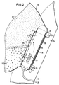
- the circle marked II delimits a section that in 2 is shown in more detail.
- the compressed gas source 16 has a tubular housing 30 which at its upper and lower ends in the form of a pipe clamp 32 or 34 is formed.
- the pipe clamps 32 and 34 extend through the wall of the gas bag 18 to the respective attachment point 26 on the backrest 14.
- the tubular housing 30 encloses a cylindrical gas generator 36 in the middle Section defined in the housing by the pipe clamps 32 and 34 is.
- the gas generator 36 is through the pipe clamps 32 and 34 also sealed in the housing 30 against the environment.
- the gas generator 36 points to its central section lying in the housing 30 Outflow openings 38 on, by him after its activation supplied gas can flow into the housing 30.
- the housing 30 forms between its inner wall and the Outer wall of the central portion of the gas generator 36, which is extends between the pipe clamps 32 and 34, a prechamber 40, via the outflow openings 38 of the gas generator 36 outflowing gas to first inflow openings 42 and second Inflow openings 44 can reach the wall of the housing 30.
- the first inflow openings 42 open into the first chamber 20 of the Gas bags 18, and the second inflow openings 44 open into the second chamber 22 of the gas bag 18. While the inflow opening 42 from three individual circular passages through the outer wall of the Housing 30 exists, the inflow opening 44 is through only two circular passageways formed.
- the one available for a flow standing free cross section of the first inflow opening 42 or second inflow opening 44 thus results from the sum of the free Individual cross sections of the circular passages.
- the free one The cross section of the first inflow opening 42 is based on the volume the first chamber 20, the pressure generated by the gas generator 36 and the Matched point in time at which an internal pressure in the first chamber 20 of 0.5 bar should be reached. With the described Embodiment is the predetermined time shortly before Impact of the vehicle occupant on the gas bag 18. In an analogous manner is the free cross section of the second inflow opening 44 on the Volume of the second chamber 22, which is generated by the gas generator 36 Pressure and the one to be reached shortly before the impact of the occupant Internal pressure of 1.5 bar matched.
- the gas generator 36 is activated via the feed lines 46, with a conventional device, not shown connected to impact detection.
- the chamber 22 is filled faster than the chamber 20, and the internal pressure of chamber 22 increases faster than the pressure in the chamber 20. It is therefore possible, at a time shortly before the Impact of a vehicle occupant on the gas bag 18 different To achieve internal pressures in chambers 20 and 22. Possibly Pressure equalization processes between the chambers 20 and 22 via the Inflow openings 42 and 44 and the pre-chamber 40 only occur later on and can focus on achieving different Internal pressures in the chambers just before an impact Do not affect vehicle occupants, or only marginally.
Abstract
Description
Die Erfindung betrifft eine Gassack-Seitenaufprall-Schutzeinrichtung für Fahrzeuginsassen mit einer Druckgasquelle und einem aufblasbaren Gassack, wobei der Gassack eine erste, seitlich des Brustkorbs eines Insassen aufblasbare Kammer und eine zweite aufblasbare Kammer aufweist.The invention relates to an airbag side impact protection device for vehicle occupants with a pressurized gas source and an inflatable Airbag, the airbag being a first, to the side of the rib cage one occupant inflatable chamber and a second inflatable chamber having.
Gassack-Seitenaufprall-Schutzeinrichtungen dieser Art sind dafür vorgesehen, einen Fahrzeuginsassen bei einem Seitenaufprall vor dem Kontakt mit der Seitenstruktur eines Fahrzeugs oder eindringenden Fahrzeugteilen zu schützen.Airbag side impact protection devices of this type are for this provided a vehicle occupant in a side impact in front of the Contact with the side structure of a vehicle or intruding Protect vehicle parts.
Aus der deutschen Offenlegungsschrift DE 195 38 657 A1 ist eine Gassack-Seitenaufprall-Schutzeinrichtung bekannt, bei der eine erste Kammer seitlich des Brustkorbs eines Insassen und eine zweite Kammer seitlich des Kopfes eines Insassen aufgeblasen wird. Die beiden Kammern sind durch einen Ausgleichskanal miteinander verbunden, über den Gas während des Aufblasvorgangs von der ersten in die zweite Kammer gelangen kann.From the German patent application DE 195 38 657 A1 is a Airbag side impact protection device known in which a first Chamber to the side of an occupant's chest and a second chamber is inflated to the side of an occupant's head. The two chambers are connected to each other by an equalizing channel Gas during inflation from the first to the second chamber can reach.
Ebenfalls bekannt sind Gassack-Seitenaufprall-Schutzeinrichtungen mit einem Gassack, der sich im aufgeblasenen Zustand seitlich des Brustkorbs und des Beckens des Fahrzeuginsassen erstreckt. Im Falle eines Seitenaufpralls wird der Insasse dann durch den Gassack im Brustkorb-/Beckenbereich abgefangen.Airbag side impact protection devices are also known with an airbag that is inflated to the side of the Chest and pelvis of the vehicle occupant extends. In the event of a side impact, the occupant is then through the gas bag in the Chest / pelvis area intercepted.
Unterschiedliche biomechanische Eigenschaften menschlicher Körperteile, z.B. des menschlichen Brustkorbs und des menschlichen Beckens, können mit den bekannten Einrichtungen nicht oder nur eingeschränkt berücksichtigt werden. Auch eine fahrzeugspezifische Belastungsverteilung mit Schwerpunkten im Becken- oder Brustkorbbereich, beispielsweise durch eine ausgeprägt hohe oder tiefe Sitzposition im Fahrzeug oder spezielle Seitenstrukturen, kann mit den bekannten Gassack-Seitenaufprall-Schutzeinrichtungen nicht oder nur unvollkommen ausgeglichen werden.Different biomechanical properties of human Body parts, e.g. of the human rib cage and the human Basin, can not or only with the known facilities be taken into account to a limited extent. Also a vehicle specific Load distribution with a focus on pelvic or Chest area, for example by a pronounced high or deep seating position in the vehicle or special side structures, can not with the known gas bag side impact protection devices or only be compensated imperfectly.
Mit der Erfindung soll eine Gassack-Seitenaufprall-Schutzeinrichtung geschaffen werden, mit der das Verletzungsrisiko beim Seitenaufprall verringert werden kann.The aim of the invention is to provide an airbag side impact protection device be created with which the risk of injury at Side impact can be reduced.
Erfindungsgemäß ist hierzu eine Gassack-Seitenaufprall-Schutzeinrichtung für Fahrzeuginsassen mit einer Druckgasquelle und einem aufblasbaren Gassack vorgesehen, bei der der Gassack eine erste, seitlich des Brustkorbs eines Insassen aufblasbare Kammer und eine zweite aufblasbare Kammer aufweist, wobei die zweite Kammer seitlich des Beckens des Insassen aufblasbar ist und die Kammern durch die Druckgasquelle so befüllbar sind, daß sie im befüllten Zustand unterschiedliche Innendrücke aufweisen. Durch die Aufteilung des Gassackvolumen in eine dem Brustkorb und eine dem Becken zugeordnete Kammer sind die Voraussetzungen für eine Anpassung der Schutzeinrichtung an die unterschiedlichen biomechanischen Eigenschaften des Brustkorb- bzw. Beckenbereichs eines Fahrzeuginsassen geschaffen. Indem die Kammern so befüllt werden, daß sie im befüllten Zustand unterschiedliche Innendrücke aufweisen, kann beispielsweise der empfindlichere Brustkorbbereich durch einen gegenüber der Beckenkammer niedrigeren Innendruck in der Brustkorbkammer weicher als das Becken abgefangen werden. Darüber hinaus kann die Schutzeinrichtung auch auf eine fahrzeugspezifische Belastungsverteilung bei einem Seitenaufprall abgestimmt werden, die sich beispielsweise durch abschnittsweise unterschiedlich stabil ausgeführte und dadurch bei einem Seitenaufprall unterschiedlich weit eindringende Seitenwände des Innenraumes im Brustkorb- bzw. Beckenbereich ergeben kann. Durch diese verbesserte Anpassung an einerseits die biomechanischen Eigenschaften des Fahrzeuginsassen und andererseits die mechanischen Eigenschaften der Fahrzeug-Seitenstruktur kann das Verletzungsrisiko beim Seitenaufprall im Vergleich zu konventionellen Gassack-Seitenaufprall-Schutzeinrichtungen verringert werden.For this purpose, an airbag side impact protection device is according to the invention for vehicle occupants with a pressurized gas source and an inflatable Airbag provided, in which the airbag a first, Inflatable chamber and a side of the chest of an occupant has second inflatable chamber, the second chamber laterally the pelvis of the occupant is inflatable and the chambers through the Compressed gas source can be filled so that they are filled have different internal pressures. By dividing the Airbag volume into one assigned to the chest and one to the pelvis Chamber are the prerequisites for an adjustment of the Protective device to the different biomechanical Properties of the chest or pelvic area of a Vehicle occupants created. By filling the chambers so that they can have different internal pressures when filled for example the more sensitive area of the rib cage with a lower internal pressure in the pelvic chamber Chest chamber to be intercepted softer than the pelvis. About that In addition, the protective device can also be set to a vehicle-specific one Load distribution can be coordinated in the event of a side impact become stable, for example, by sections executed and therefore different distances in the event of a side impact penetrating side walls of the interior in the rib cage or Pelvic area can result. Through this improved customization on the one hand the biomechanical properties of the vehicle occupant and on the other hand the mechanical properties of the vehicle side structure can compare the risk of injury from side impact reduced to conventional gas bag side impact protection devices become.
In Weiterbildung der Erfindung ist vorgesehen, daß der Druck in der ersten Kammer im Bereich von 0,5 bar liegt und der Druck in der zweiten Kammer im Bereich von 1,5 bar liegt. Durch diese Maßnahmen weist der Gassack im Beckenbereich einen höheren Innendruck auf als im empfindlicheren Abdomen- und Brustkorbbereich, so daß trotz optimaler Schutzwirkung beim Seitenaufprall durch den hohen Druck in der Beckenkammer die Belastung für den Abdomen- und Brustkorbbereich des Insassen reduziert wird.In a development of the invention it is provided that the pressure in the first chamber is in the range of 0.5 bar and the pressure in the second chamber is in the range of 1.5 bar. Through these measures the gas bag in the pool area has a higher internal pressure than in the more sensitive abdomen and chest area, so that despite optimal protection in the event of a side impact due to the high pressure in the pelvic chamber the burden on the abdomen and chest area of the occupant is reduced.
Die Erfindung weiterbildende Maßnahmen sehen vor, daß die Druckgasquelle einen einzigen Gasgenerator und ein den Gasgenerator wenigstens teilweise umschließendes Gehäuse aufweist und das Gehäuse wenigstens eine erste, in die erste Kammer mündende Einströmöffnung und wenigstens eine zweite, in die zweite Kammer mündende Einströmöffnung hat, wobei der freie Querschnitt der ersten bzw. zweiten Einströmöffnung auf das Volumen der ersten bzw. zweiten Kammer, die Druckgasquelle und den zu einem vorbestimmten Zeitpunkt in der ersten bzw. zweiten Kammer zu erreichenden Innendruck abgestimmt ist. Hierdurch kann eine gegenüber konventionellen Systemen verbesserte Schutzwirkung mit nur einem Gasgenerator erreicht werden, so daß der bauliche Mehraufwand gering bleibt. Die unterschiedlichen Innendrücke in den Kammern werden durch eine entsprechende Dimensionierung der Einströmöffnungen in die erste bzw. zweite Kammer erreicht, so daß die Schutzeinrichtung einfach und kostengünstig ausgeführt werden kann. Die entsprechende Dimensionierung der Einströmöffnungen ist für die Erzielung unterschiedlicher Innendrücke in den Kammern ausreichend, da unterschiedliche Innendrücke in den Kammern nur zu einem vorbestimmten Zeitpunkt im befüllten Zustand erreicht werden müssen. Während des sehr schnell erfolgenden Aufblasvorgangs der Kammern und bis zum Aufprall des Fahrzeuginsassen kann es zu keinem Ausgleich der Innendrücke in den beiden Kammern kommen. Die Abstimmung des freien Querschnitts der Einströmöffnungen auf die Druckgasquelle erfolgt insbesondere hinsichtlich des von der Druckgasquelle erzeugten Drucks. Es ist dabei ausreichend, daß die Kammern zu einem vorbestimmten Zeitpunkt einen unterschiedlichen Innendruck aufweisen, beispielsweise zu dem Zeitpunkt, zu dem der Aufprall eines Fahrzeuginsassen erwartet wird. Die Schutzeinrichtung muß damit nicht dahingehend ausgelegt werden, daß die Kammern im statischen Zustand unterschiedliche Innendrücke aufweisen; vielmehr genügt ein unterschiedlicher Innendruck in den Kammern zu dem vorbestimmten Zeitpunkt während der dynamischen Vorgänge der Gassackbefüllung und auch noch bei befülltem Gassack. Aufgrund dieser Auslegung, mit der unterschiedliche Innendrücke lediglich zu einem vorbestimmten Zeitpunkt im befüllten Zustand der Kammern erreicht werden sollen, kann auf konstruktive Maßnahmen zur Sicherstellung eines statischen Druckhaltevermögens der Kammern verzichtet und der Aufbau der Schutzeinrichtung einfach gestaltet werden.The invention further measures provide that the pressurized gas source a single gas generator and one the gas generator has at least partially enclosing housing and the housing at least one first inflow opening opening into the first chamber and at least one second inflow opening opening into the second chamber has, the free cross section of the first or second Inflow opening on the volume of the first and second chamber, respectively Pressurized gas source and at a predetermined time in the first or the second chamber to be achieved internal pressure is matched. Hereby can be improved over conventional systems Protective effect can be achieved with only one gas generator, so that the additional structural effort remains low. The different internal pressures in the chambers are dimensioned accordingly Inflow openings in the first or second chamber reached so that the protective device can be designed simply and inexpensively can. The corresponding dimensioning of the inflow openings is for the achievement of different internal pressures in the chambers sufficient, as different internal pressures in the chambers only too a predetermined time can be reached in the filled state have to. During the very rapid inflation process Chamber and until the impact of the vehicle occupant can no one Equalization of the internal pressures in the two chambers come. The Matching the free cross-section of the inflow openings to the Compressed gas source takes place in particular with regard to the Pressurized gas source generated pressure. It is sufficient that the Chambers a different at a predetermined time Have internal pressure, for example at the time when the Impact of a vehicle occupant is expected. The protective device need not be interpreted in such a way that the chambers in static state have different internal pressures; much more A different internal pressure in the chambers suffices for that predetermined time during the dynamic operations of the Airbag filling and even when the airbag is filled. Based on these Interpretation with which different internal pressures only become one predetermined time in the filled state of the chambers reached can be used to ensure constructive measures a static pressure retention capacity of the chambers and the Structure of the protective device can be designed easily.
Vorteilhafterweise weist das Gehäuse eine mit dem Gasgenerator und der ersten und zweiten Einströmöffnung in Strömungsverbindung stehende Vorkammer auf. Das Vorsehen einer Vorkammer erleichtert die Aufteilung des von dem Gasgenerator gelieferten Gasstroms auf die erste bzw. zweite Einströmöffnung und damit auf die erste bzw. zweite Kammer.The housing advantageously has one with the gas generator and the first and second inflow openings in fluid communication standing antechamber. The provision of an antechamber facilitates this Distribution of the gas flow supplied by the gas generator to the first or second inflow opening and thus to the first or second Chamber.
In Weiterbildung der Erfindung ist der Gassack zur Bildung der ersten und der zweiten Kammer mit einer Trennaht versehen. Eine solche Ausbildung ermöglicht eine einfache Herstellung des Gassacks. Auch verringert eine Trennaht zwischen der ersten, seitlich des Brustkorbs eines Insassen aufblasbaren Kammer und der zweiten, seitlich des Beckens des Insassen aufblasbaren Kammer das Gassackvolumen im Abdomenbereich des Insassen und entlastet damit diesen empfindlichen Bereich.In a further development of the invention, the gas bag is used to form the provide first and second chamber with a seam. A such training enables easy manufacture of the gas bag. Also, a separating seam between the first, to the side of the Chest of an occupant inflatable chamber and the second, inflatable chamber to the side of the pelvis of the occupant Airbag volume in the abdomen area of the occupant and thus relieves this sensitive area.
Es ist vorteilhaft, daß die Druckgasquelle und der Gassack im gefalteten Zustand in die Rückenlehne eines Fahrzeugsitzes integriert sind. Unabhängig von der Stellung der Rückenlehne bleibt die Lage der Kammern zum Insassen damit im wesentlichen gleich, und eine Veränderung der Schutzwirkung durch Verstellen des Sitzes ist ausgeschlossen.It is advantageous that the compressed gas source and the gas bag in the folded Condition integrated into the backrest of a vehicle seat are. Regardless of the position of the backrest, the position of the Chambers to the occupant are essentially the same, and a change the protective effect by adjusting the seat is excluded.
Schließlich ist vorgesehen, daß eine Steuereinheit und mit der Steuereinheit verbundene Mittel zum Ändern des freien Querschnitts der ersten und/oder zweiten Einströmöffnung vorgesehen sind. Diese Maßnahmen erlauben eine Anpassung der Gassack-Seitenaufprall-Schutzeinrichtung hinsichtlich der Innendrücke, die in den Kammern erreicht werden, während des Betriebs eines Fahrzeugs an Parameter, die die Schutzwirkung beeinflussen können, beispielsweise das Gewicht und die Größe eines Insassen, die Umgebungstemperatur oder die Fahrgeschwindigkeit. Diese Parameter werden über Sensoren erfaßt und in der Steuereinheit ausgewertet. Die Steuereinheit ändert dann entsprechend dem Ergebnis der Auswertung den freien Querschnitt der ersten und/oder zweiten Einströmöffnung, beispielsweise über elektrisch aktivierbare Schieber oder Blenden.Finally, it is provided that a control unit and with the Control unit connected means for changing the free cross section the first and / or second inflow opening are provided. This Measures allow the gas bag side impact protection device to be adapted regarding the internal pressures that are reached in the chambers are, during the operation of a vehicle to parameters that the Can affect protective effect, such as weight and Size of an occupant, the ambient temperature or the driving speed. These parameters are recorded via sensors and in the Control unit evaluated. The control unit then changes accordingly the result of the evaluation the free cross section of the first and / or second inflow opening, for example, electrically activatable sliders or panels.
Weitere Merkmale und Vorteile der Erfindung ergeben sieh aus der
folgenden Beschreibung und aus der Zeichnung, auf die Bezug genommen
wird. In der Zeichnung zeigen:
In der Figur 1 ist ein Fahrzeuginsasse 10 dargestellt, der in
einem Fahrzeugsitz 12 sitzt. Der Fahrzeugsitz 12 weist eine Rückenlehne
14 auf, in die eine erfindungsgemäße Gassack-SeitenaufprallSchutzeinrichtung
integriert ist. Die Gassack-Seitenaufprall-Schutzeinrichtung
ist in Figur 1 im aktivierten Zustand dargestellt und
weist eine Druckgasquelle 16 und einen aufblasbaren Gassack 18 auf.
Der Gassack 18 hat wiederum eine erste Kammer 20, die seitlich des
Brustkorbs des Insassen 10 aufgeblasen ist. Eine zweite Kammer 22 des
Gassacks 18 ist seitlich des Beckens des Insassen 10 aufgeblasen. Die
beiden Kammern 20, 22 weisen einen unterschiedlichen Innendruck auf,
was in der Figur 1 durch eine unterschiedliche Markierung des Innenbereichs
der Kammern 20, 22 angedeutet ist. Die Kammern 20 und 22 des
Gassacks 18 sind dabei durch eine Trennaht 24 vollständig voneinander
getrennt. Um den gegenüber dem Becken des Insassen empfindlicheren
Brustkorbbereich des Insassen 10 zu schützen, beträgt der Innendruck
der ersten Kammer 20 etwa 0,5 bar, wohingegen der Innendruck in der
seitlich des Beckens aufgeblasenen zweiten Kammer 22 bei 1,5 bar
liegt. Figur 1 stellt die Gassack-Seitenaufprall-Schutzeinrichtung zu
einem Zeitpunkt dar, der kurz vor dem Aufprall des Fahrzeuginsassen
10 auf den Gassack 18 liegt. Zu diesem Zeitpunkt weisen die Kammern
20, 22 die zuvor erwähnten unterschiedlichen Innendrücke auf, so daß
der Brustkorb- bzw. der Beckenbereich des Insassen 10 beim Aufprall
auf die Kammer 20, 22 des Gassacks 18 unterschiedlich stark belastet
werden.A
Der mit II bezeichnete Kreis umgrenzt einen Ausschnitt, der in der Figur 2 detaillierter dargestellt ist.The circle marked II delimits a section that in 2 is shown in more detail.
In der Teilschnittansicht der Figur 2 ist zunächst die
Rückenlehne 14 zu erkennen, an der die Druckgasquelle 16 in
konventioneller Weise an Befestigungspunkten 26 befestigt ist. Die
Druckgasquelle 16 ist im wesentlichen innerhalb des Gassacks 18
angeordnet, die Befestigungspunkte 26 liegen aber außerhalb des
Volumens des Gassacks 18. Ebenfalls zu erkennen ist die Kammer 20 und
die Kammer 22 des Gassacks 18, die durch die Trennaht 24 vollständig
voneinander getrennt sind. An dem der Druckgasquelle 16 zugewandten
Ende der Trennaht 24 ist eine Verstärkung 28 angeordnet, die das
Ausreißen der Trennaht 24 während des Aufblasvorgangs und während des
Aufpralls verhindert und dadurch die vollständige Trennung der
Kammern 20 und 22 auch im aufgeblasenen Zustand des Gassacks 18
sicherstellt.In the partial sectional view of Figure 2 is first of all
To recognize the
Die Druckgasquelle 16 weist ein rohrförmiges Gehäuse 30 auf, das
an seinem oberen und unteren Ende jeweils in Form einer Rohrschelle
32 bzw. 34 ausgebildet ist. Die Rohrschellen 32 und 34 erstrecken
sich durch die Wandung des Gassacks 18 hindurch zu dem jeweiligen Befestigungspunkt
26 an der Rückenlehne 14. Das rohrförmige Gehäuse 30
umschließt einen zylindrischen Gasgenerator 36 in dessen mittleren
Abschnitt, der in dem Gehäuse durch die Rohrschellen 32 und 34 festgelegt
ist. Durch die Rohrschellen 32 und 34 ist der Gasgenerator 36
auch in dem Gehäuse 30 gegen die Umgebung abgedichtet. Der Gasgenerator
36 weist auf seinem im Gehäuse 30 liegenden mittleren Abschnitt
Ausströmöffnungen 38 auf, über die von ihm nach seiner Aktivierung
geliefertes Gas in das Gehäuse 30 strömen kann. The
Das Gehäuse 30 bildet dabei zwischen seiner Innenwandung und der
Außenwandung des mittleren Abschnitts des Gasgenerators 36, der sich
zwischen den Rohrschellen 32 und 34 erstreckt, eine Vorkammer 40,
über die aus den Ausströmöffnungen 38 des Gasgenerators 36
ausströmendes Gas zu ersten Einströmöffnungen 42 und zweiten
Einströmöffnungen 44 in der Wandung des Gehäuses 30 gelangen kann.
Die ersten Einströmöffnungen 42 münden in die erste Kammer 20 des
Gassacks 18, und die zweiten Einströmöffnungen 44 münden in die
zweite Kammer 22 des Gassacks 18. Während die Einströmöffnung 42 aus
drei einzelnen kreisförmigen Durchgängen durch die Außenwandung des
Gehäuses 30 besteht, ist die Einströmöffnung 44 durch nur zwei
kreisförmige Durchgänge gebildet. Der für eine Strömung zur Verfügung
stehende freie Querschnitt der ersten Einströmöffnung 42 bzw. der
zweiten Einströmöffnung 44 ergibt sich damit aus der Summe der freien
Einzelquerschnitte der kreisförmigen Durchgänge. Der freie
Querschnitt der ersten Einströmöffnung 42 ist dabei auf das Volumen
der ersten Kammer 20, den vom Gasgenerator 36 erzeugten Druck und den
Zeitpunkt abgestimmt, zu dem in der ersten Kammer 20 ein Innendruck
von 0,5 bar erreicht werden soll. Bei der beschriebenen
Ausführungsform liegt der vorbestimmte Zeitpunkt kurz vor dem
Aufprall des Fahrzeuginsassen auf den Gassack 18. In analoger Weise
ist der freie Querschnitt der zweiten Einströmöffnung 44 auf das
Volumen der zweiten Kammer 22, den vom Gasgenerator 36 erzeugten
Druck und den kurz vor dem Aufprall des Insassen zu erreichenden
Innendruck von 1,5 bar abgestimmt.The
Die Aktivierung des Gasgenerators 36 erfolgt über die Zuleitungen
46, die mit einer nicht dargestellten, konventionellen Einrichtung
zur Aufprallerkennung verbunden sind.The
Nach Aktivierung des Gasgenerators 36 strömt von diesem erzeugtes
Gas aus den Ausströmöffnungen 38 in die Vorkammer 40 und durch die
Einströmöffnungen 42 bzw. 44 in die Kammern 20 bzw. 22. In der Vorkammer
40 entsteht infolgedessen ein Überdruck, und die in die
Kammern 20, 22 abströmende Gasmenge ist im wesentlichen durch den
Druck in der Vorkammer 40 und den freien Querschnitt der jeweils
zugeordneten Einströmöffnungen 42, 44 bestimmt. Um in der Kammer 22
einen höheren Innendruck als in der Kammer 20 zu erreichen, ist der
freie Querschnitt der Einströmöffnung 44 daher größer als der freie
Querschnitt, der erforderlich wäre, um die Kammer 22 gleich schnell
und mit dem gleichen Innendruck wie die Kammer 20 zu füllen.
Infolgedessen wird die Kammer 22 schneller befüllt als die Kammer 20,
und der Innendruck der Kammer 22 steigt schneller an als der Druck in
der Kammer 20. Es ist daher möglich, zu einem Zeitpunkt kurz vor dem
Aufprall eines Fahrzeuginsassen auf den Gassack 18 unterschiedliche
Innendrücke in den Kammern 20 und 22 zu erreichen. Eventuelle
Druckausgleichvorgänge zwischen den Kammern 20 und 22 über die
Einströmöffnungen 42 und 44 und die Vorkammer 40 treten dabei erst
später auf und können sich auf die Erzielung unterschiedlicher
Innendrücke in den Kammern kurz vor dem Aufprall eines
Fahrzeuginsassen nicht oder nur unwesentlich auswirken.After activation of the
Claims (7)
Applications Claiming Priority (2)
| Application Number | Priority Date | Filing Date | Title |
|---|---|---|---|
| DE29822159U DE29822159U1 (en) | 1998-12-11 | 1998-12-11 | Airbag side impact protection device |
| DE29822159U | 1998-12-11 |
Publications (2)
| Publication Number | Publication Date |
|---|---|
| EP1008494A2 true EP1008494A2 (en) | 2000-06-14 |
| EP1008494A3 EP1008494A3 (en) | 2002-04-24 |
Family
ID=8066538
Family Applications (1)
| Application Number | Title | Priority Date | Filing Date |
|---|---|---|---|
| EP99123960A Withdrawn EP1008494A3 (en) | 1998-12-11 | 1999-12-06 | Side impact airbag protection device |
Country Status (4)
| Country | Link |
|---|---|
| US (1) | US6349964B1 (en) |
| EP (1) | EP1008494A3 (en) |
| JP (1) | JP2000177527A (en) |
| DE (1) | DE29822159U1 (en) |
Cited By (12)
| Publication number | Priority date | Publication date | Assignee | Title |
|---|---|---|---|---|
| WO2002100691A1 (en) * | 2001-06-08 | 2002-12-19 | Toyoda Gosei Co., Ltd. | Side air bag device |
| WO2002100690A1 (en) * | 2001-06-08 | 2002-12-19 | Toyoda Gosei Co., Ltd. | Side airbag device |
| WO2002081267A3 (en) * | 2001-04-05 | 2003-03-20 | Delphi Tech Inc | Airbag module for a seat |
| EP1344694A2 (en) | 2002-03-11 | 2003-09-17 | Toyoda Gosei Co., Ltd. | Side airbag apparatus |
| WO2004098957A1 (en) * | 2003-05-10 | 2004-11-18 | Autoliv Development Ab | Airbag assembly for a motor vehicle |
| DE102004006319A1 (en) * | 2004-02-10 | 2005-09-15 | Autoliv Development Ab | Airbag unit, especially for mounting on vehicle seat, has housing wall with at least two half shells joined to each other and through opening for ignition cable located entirely within one of the two half shells |
| WO2006074749A1 (en) * | 2004-12-24 | 2006-07-20 | Autoliv Development Ab | Protective device for vehicle passengers, and method for the production of a multichamber gas bag |
| WO2006131351A1 (en) * | 2005-06-10 | 2006-12-14 | Autoliv Development Ab | Airbag unit and method for producing an airbag unit |
| US7152876B2 (en) | 2003-01-31 | 2006-12-26 | Trw Occupant Restraint Systems Gmbh & Co. Kg | Gas bag for a side impact protection device |
| CN103303245A (en) * | 2012-03-08 | 2013-09-18 | 通用汽车环球科技运作有限责任公司 | Protective device for a motor vehicle |
| US20200262383A1 (en) * | 2019-02-15 | 2020-08-20 | Ford Global Technologies, Llc | Side airbag including spacer chamber |
| EP3808611A1 (en) * | 2019-10-17 | 2021-04-21 | Autoliv Development AB | Side airbag apparatus |
Families Citing this family (87)
| Publication number | Priority date | Publication date | Assignee | Title |
|---|---|---|---|---|
| DE19904739A1 (en) * | 1999-02-05 | 2000-08-10 | Volkswagen Ag | Safety device for a motor vehicle with a side airbag |
| DE29921743U1 (en) | 1999-12-10 | 2000-04-13 | Trw Repa Gmbh | Vehicle occupant restraint system |
| DE10020920B4 (en) * | 2000-04-28 | 2010-07-22 | GM Global Technology Operations, Inc., Detroit | Side impact protection device for an occupant of a motor vehicle |
| US7093851B2 (en) | 2001-03-13 | 2006-08-22 | Delphi Technologies, Inc. | Tunable control side air bag cushion |
| US6561541B2 (en) * | 2001-07-11 | 2003-05-13 | Delphi Technologies, Inc. | Side air bag incorporating inverted T-shaped flow barrier |
| EP1463652B2 (en) * | 2002-01-04 | 2009-08-19 | TAKATA-PETRI (Ulm) GmbH | Gas flow distributor for a lateral airbag module |
| US7055853B2 (en) * | 2002-01-31 | 2006-06-06 | Honda Giken Kogyo Kabushiki Kaisha | Side airbag apparatus |
| JP3915544B2 (en) * | 2002-02-25 | 2007-05-16 | タカタ株式会社 | Airbag device |
| JP3972688B2 (en) * | 2002-03-11 | 2007-09-05 | 豊田合成株式会社 | Side airbag device for vehicle |
| JP3741075B2 (en) * | 2002-04-12 | 2006-02-01 | トヨタ自動車株式会社 | Inflator |
| DE10223830A1 (en) * | 2002-05-28 | 2004-01-08 | Takata Corp. | Multi-part gas bag blank for an airbag of an occupant protection device for motor vehicles and method for producing an airbag from the airbag blank |
| JP4206291B2 (en) * | 2002-07-08 | 2009-01-07 | 本田技研工業株式会社 | Side airbag device |
| DE10236859A1 (en) | 2002-08-07 | 2004-02-19 | Takata Corp. | Gas bag for airbag module has control belt connected to gas bag cover near outflow orifice to invert part of cover on reaching predetermined unfolded state into gas bag to close orifice |
| US7168734B2 (en) | 2002-10-01 | 2007-01-30 | Daicel Chemical Industries, Ltd. | Inflator for air bag |
| JP4113439B2 (en) | 2002-10-01 | 2008-07-09 | ダイセル化学工業株式会社 | Inflator for airbag |
| DE10257248A1 (en) * | 2002-12-07 | 2004-07-08 | Dr.Ing.H.C. F. Porsche Ag | Motor vehicle with a body structure and with a side impact protection device |
| JP4161705B2 (en) * | 2002-12-19 | 2008-10-08 | タカタ株式会社 | Side airbag and side airbag device |
| US7168733B2 (en) * | 2002-12-27 | 2007-01-30 | Takata Corporation | Airbag apparatus |
| EP2108548A3 (en) * | 2003-01-20 | 2009-11-25 | Toyota Jidosha Kabushiki Kaisha | Vehicle occupant protection device |
| US20040183285A1 (en) * | 2003-01-29 | 2004-09-23 | Mazda Motor Corporation | Airbag device for vehicle |
| JP4285167B2 (en) * | 2003-01-30 | 2009-06-24 | タカタ株式会社 | Side airbag device |
| JP2004243976A (en) * | 2003-02-17 | 2004-09-02 | Takata Corp | Airbag device for side impact |
| GB2402111A (en) * | 2003-05-27 | 2004-12-01 | Autoliv Dev | Air bag with two chambers sealed by a strap |
| GB2402912A (en) * | 2003-06-20 | 2004-12-22 | Autoliv Dev | Side air-bag |
| US7063350B2 (en) * | 2003-09-23 | 2006-06-20 | Autoliv Asp, Inc. | Dual chamber side airbag apparatus and method |
| GB2406312A (en) * | 2003-09-25 | 2005-03-30 | Autoliv Dev | Gas deflector |
| US20050104342A1 (en) * | 2003-11-17 | 2005-05-19 | Ford Global Technologies, Llc | An improved side airbag |
| US7207596B2 (en) | 2003-12-08 | 2007-04-24 | Dr. Ing H.C.F. Porsche Aktiengesellschaft | Motor vehicle with a body structure and with a side impact protection device |
| DE10360468A1 (en) * | 2003-12-22 | 2005-08-04 | Trw Occupant Restraint Systems Gmbh & Co. Kg | Airbag module |
| DE102004001263A1 (en) * | 2004-01-08 | 2005-08-04 | Autoliv Development Ab | Airbag module for vehicle occupant safety has at least one gas through opening fitted with valve, whereby valve and/or one or more valve actuators is/are formed from material with so-called shape memory |
| US7384062B2 (en) | 2004-01-28 | 2008-06-10 | Nihon Plast Co., Ltd. | Airbag system |
| JP2005247272A (en) * | 2004-02-06 | 2005-09-15 | Takata Corp | Air bag apparatus |
| JP4734933B2 (en) * | 2004-02-27 | 2011-07-27 | タカタ株式会社 | Vehicle occupant protection system and inflator |
| US7347444B2 (en) * | 2004-05-06 | 2008-03-25 | Autoliv Asp, Inc. | Inflatable airbag with overlapping chamber |
| DE202004009002U1 (en) * | 2004-06-08 | 2004-08-12 | Autoliv Development Ab | Vehicle seat unit |
| US20060022439A1 (en) * | 2004-07-30 | 2006-02-02 | Trw Vehicle Safety Systems Inc. | Inflatable vehicle occupant protection device with differentially pressurized chambers |
| DE502005003767D1 (en) * | 2004-08-19 | 2008-05-29 | Autoliv Dev | GASSACK FOR THE PROTECTION OF A VEHICLE'S INTAKE |
| US7316415B2 (en) * | 2004-08-30 | 2008-01-08 | Autoliv Asp, Inc. | Dual chamber airbag |
| JP4584678B2 (en) * | 2004-11-04 | 2010-11-24 | ダイセル化学工業株式会社 | Multistage gas generator |
| JP5004587B2 (en) * | 2004-11-05 | 2012-08-22 | オートリブ ディベロップメント エービー | Side airbag device and side airbag system |
| EP1657122A3 (en) * | 2004-11-16 | 2006-10-18 | Takata Corporation | Airbag apparatus |
| JP4827046B2 (en) * | 2004-11-16 | 2011-11-30 | タカタ株式会社 | Airbag device |
| US20060131845A1 (en) * | 2004-12-22 | 2006-06-22 | Ford Global Technologies, Llc | A multi-chambered air bag for a motor vehicle |
| KR20060084101A (en) | 2005-01-17 | 2006-07-24 | 삼성에스디아이 주식회사 | Plasma display device and driving method thereof |
| DE202005000999U1 (en) * | 2005-01-21 | 2006-06-01 | Trw Automotive Safety Systems Gmbh & Co. Kg | Airbag module for vehicles has airbag whose wall in the first position has a fold whereby retaining means can be actively detached on the signal and the fold is opened in the second position of airbag |
| US7661708B2 (en) * | 2005-01-21 | 2010-02-16 | Trw Automotive Safety Systems Gmbh | Gas bag module |
| US7338070B2 (en) * | 2005-03-14 | 2008-03-04 | Ford Global Technologies, Llc | Multi-chambered air bag for a motor vehicle |
| JP4857825B2 (en) * | 2005-05-31 | 2012-01-18 | 豊田合成株式会社 | Crew protection method and protection structure |
| CN100441448C (en) * | 2005-05-31 | 2008-12-10 | 丰田合成株式会社 | Method and structure for protecting occupant |
| JP4640049B2 (en) * | 2005-08-31 | 2011-03-02 | トヨタ自動車株式会社 | Knee protection bag integrated airbag device for passenger seat |
| JP4640053B2 (en) * | 2005-09-07 | 2011-03-02 | トヨタ自動車株式会社 | Knee protection bag integrated airbag device for passenger seat |
| JP2007098991A (en) * | 2005-09-30 | 2007-04-19 | Toyoda Gosei Co Ltd | Side airbag device |
| JP4923529B2 (en) * | 2005-11-14 | 2012-04-25 | タカタ株式会社 | Crew restraint system |
| US20070108745A1 (en) * | 2005-11-17 | 2007-05-17 | Ford Global Technologies, Llc | Side impact airbag |
| WO2007062681A1 (en) | 2005-12-01 | 2007-06-07 | Takata-Petri Ag | Airbag system |
| KR100735998B1 (en) | 2005-12-21 | 2007-07-06 | 현대모비스 주식회사 | Side Air-Bag |
| DE602006007208D1 (en) * | 2006-02-21 | 2009-07-23 | Ford Global Tech Llc | A deployment force concentration system for a seat-mounted airbag |
| US7448645B2 (en) * | 2006-03-31 | 2008-11-11 | Ford Global Technologies, Llc | Contoured side impact airbag |
| JP2007276522A (en) * | 2006-04-03 | 2007-10-25 | Toyoda Gosei Co Ltd | Side airbag device |
| DE102006026839A1 (en) | 2006-06-09 | 2007-12-27 | GM Global Technology Operations, Inc., Detroit | Side airbag module and safety device for a motor vehicle with such a side airbag module |
| DE202006010878U1 (en) | 2006-07-11 | 2006-09-21 | Takata-Petri Ag | Airbag arrangement for vehicle occupant restraint system has chamber section that extends forward when airbag inflated to protect occupant including for forward occupant movements at angle by catching associated occupant body regions |
| JP5105883B2 (en) * | 2007-01-15 | 2012-12-26 | 日本プラスト株式会社 | Airbag device |
| US7278656B1 (en) * | 2007-01-30 | 2007-10-09 | Key Safety Systems, Inc. | Seat mounted side impact airbag module |
| JP4952321B2 (en) * | 2007-03-20 | 2012-06-13 | 豊田合成株式会社 | Side airbag device |
| JP5001702B2 (en) * | 2007-03-30 | 2012-08-15 | 日本プラスト株式会社 | Airbag device |
| DE102007031622B4 (en) * | 2007-07-06 | 2013-07-11 | Autoliv Development Ab, Patent Department Sweden | Vehicle seat pelvisbag with inside and outside airbag |
| EP2019001B1 (en) * | 2007-07-27 | 2012-06-13 | Dalphi Metal España, S.A. | Dual chamber airbag module with anti-return difuser. |
| DE102007056848B4 (en) * | 2007-11-26 | 2018-10-11 | GM Global Technology Operations LLC (n. d. Ges. d. Staates Delaware) | Side airbag system, backrest and headrest |
| JP5125596B2 (en) * | 2008-02-22 | 2013-01-23 | 豊田合成株式会社 | Side airbag device |
| DE102008026795A1 (en) | 2008-06-02 | 2009-12-10 | Takata-Petri Ag | airbag module |
| JP5369784B2 (en) * | 2009-03-13 | 2013-12-18 | マツダ株式会社 | Vehicle interior structure |
| JP4892572B2 (en) | 2009-02-12 | 2012-03-07 | トヨタ自動車株式会社 | Side airbag device and method for manufacturing side airbag |
| EP2431237B1 (en) | 2009-05-11 | 2014-04-30 | Toyota Jidosha Kabushiki Kaisha | Side airbag device for vehicle |
| WO2011016107A1 (en) * | 2009-08-03 | 2011-02-10 | トヨタ自動車株式会社 | Side airbag device for vehicle |
| CN102695634B (en) | 2009-12-21 | 2014-11-19 | 丰田自动车株式会社 | Side airbag device and method of sewing side airbag |
| JP5278344B2 (en) * | 2010-02-01 | 2013-09-04 | トヨタ自動車株式会社 | Side airbag device for vehicle |
| KR101905874B1 (en) | 2012-05-03 | 2018-10-08 | 현대모비스 주식회사 | Side airbag apparatus |
| JP6004576B2 (en) | 2012-11-28 | 2016-10-12 | 日本プラスト株式会社 | Airbag |
| JP2014184852A (en) | 2013-03-22 | 2014-10-02 | Toyota Motor Corp | Vehicular side airbag device |
| JP5907135B2 (en) | 2013-09-19 | 2016-04-20 | トヨタ自動車株式会社 | Side airbag device for vehicle |
| US9108587B2 (en) | 2013-10-08 | 2015-08-18 | Autoliv Asp, Inc. | 3-layer “C” shaped side airbag |
| JP6422911B2 (en) * | 2015-04-14 | 2018-11-14 | オートリブ ディベロップメント エービー | Side airbag device |
| US10766448B2 (en) * | 2018-06-01 | 2020-09-08 | Autoliv Asp, Inc. | Side airbag assembly |
| US10821928B2 (en) | 2018-10-10 | 2020-11-03 | Ford Global Technologies, Llc | Vehicle airbag operation |
| US10843654B2 (en) | 2019-04-26 | 2020-11-24 | Autoliv Asp, Inc. | Side airbag assembly |
| US11052860B2 (en) | 2019-05-12 | 2021-07-06 | Hyundai Motor Company | Distribution of gas for airbag inflation in a vehicle |
| US11479201B2 (en) * | 2020-02-20 | 2022-10-25 | Schroth Safety Products Llc | Chamber adjustable stiffness airbag |
Citations (1)
| Publication number | Priority date | Publication date | Assignee | Title |
|---|---|---|---|---|
| DE19538657A1 (en) | 1995-10-17 | 1997-04-24 | Trw Repa Gmbh | Airbag side impact protection device |
Family Cites Families (26)
| Publication number | Priority date | Publication date | Assignee | Title |
|---|---|---|---|---|
| JPH081155Y2 (en) * | 1987-12-24 | 1996-01-17 | 日産自動車株式会社 | Vehicle airbag device |
| US5310214A (en) * | 1992-04-02 | 1994-05-10 | Talley Automotive Products, Inc. | Air bag system for restraining movement of an adult and/or a child |
| US5221109A (en) * | 1992-07-23 | 1993-06-22 | Morton International, Inc. | Airbag inflator having vents to terminate inflation |
| US5366242A (en) * | 1993-11-01 | 1994-11-22 | Trw Vehicle Safety Systems Inc. | Apparatus for controlling inflation of an air bag |
| US5524924A (en) * | 1993-11-15 | 1996-06-11 | Trw Vehicle Safety Systems Inc. | Method and apparatus for restraining an occupant of a vehicle upon a side impact against the vehicle |
| US5573271A (en) * | 1994-11-18 | 1996-11-12 | Trw Inc. | Side impact air bag inflator |
| US5556128A (en) * | 1994-11-24 | 1996-09-17 | Volkswagen Ag | Safety arrangement for a vehicle occupant |
| US5586782A (en) * | 1995-06-26 | 1996-12-24 | Alliedsignal Inc. | Dual pressure side impact air bag |
| US5520413A (en) * | 1995-09-11 | 1996-05-28 | Morton International, Inc. | Partitioned multi-cell air bag |
| WO1997014586A1 (en) * | 1995-10-16 | 1997-04-24 | Breed Automotive Technology, Inc. | Side impact air bag |
| DE29517951U1 (en) * | 1995-11-13 | 1996-02-08 | Trw Repa Gmbh | Airbag for a vehicle occupant restraint system |
| US6065773A (en) * | 1996-01-19 | 2000-05-23 | Klinger; Barney | Gas pressure restraint, sensing and release systems |
| US5718450A (en) * | 1996-01-19 | 1998-02-17 | Takata, Inc. | Inflatable restraint system having a head/thorax cushion for side impact protection |
| US5913536A (en) * | 1996-02-07 | 1999-06-22 | Trw Vehicle Safety System Inc. | Air bag module |
| DE19620617C2 (en) * | 1996-05-22 | 1998-04-09 | Autoliv Dev | Airbag arrangement with inflation control |
| US5873598A (en) * | 1996-08-27 | 1999-02-23 | Toyo Tire & Rubber Co., Ltd. | Air bag device |
| DE19647611A1 (en) * | 1996-11-18 | 1998-05-20 | Opel Adam Ag | Airbag module, especially for protecting vehicle passenger against side impact |
| US6089598A (en) * | 1996-11-22 | 2000-07-18 | Autoliv Asp, Inc. | Pyrotechnic inflator with reduced extent filter and cartridge charges |
| US6039346A (en) * | 1997-01-17 | 2000-03-21 | General Motors Corporation | Air bag module with variable inflation |
| US5853191A (en) * | 1997-02-06 | 1998-12-29 | Alliedsignal Inc. | Vehicle restraint system with inflation control |
| US5791685A (en) * | 1997-02-20 | 1998-08-11 | Alliedsignal Inc. | Three-chambered side impact air bag |
| DE19720588A1 (en) * | 1997-05-16 | 1998-11-19 | Porsche Ag | Impact protection device for an occupant of a vehicle |
| DE19725122A1 (en) * | 1997-06-13 | 1998-12-17 | Hs Tech & Design | Protection device against a side impact in a motor vehicle |
| US6059311A (en) * | 1998-02-21 | 2000-05-09 | Breed Automotive Technology, Inc. | Pillar-mounted side impact and rollover air bag |
| DE19814054A1 (en) * | 1998-03-30 | 1999-10-07 | Opel Adam Ag | Side impact protection device |
| US6158769A (en) * | 1998-05-29 | 2000-12-12 | Trw Inc. | Inflator slope control device |
-
1998
- 1998-12-11 DE DE29822159U patent/DE29822159U1/en not_active Expired - Lifetime
-
1999
- 1999-12-06 EP EP99123960A patent/EP1008494A3/en not_active Withdrawn
- 1999-12-08 JP JP11348325A patent/JP2000177527A/en active Pending
- 1999-12-10 US US09/458,903 patent/US6349964B1/en not_active Expired - Lifetime
Patent Citations (1)
| Publication number | Priority date | Publication date | Assignee | Title |
|---|---|---|---|---|
| DE19538657A1 (en) | 1995-10-17 | 1997-04-24 | Trw Repa Gmbh | Airbag side impact protection device |
Cited By (20)
| Publication number | Priority date | Publication date | Assignee | Title |
|---|---|---|---|---|
| WO2002081267A3 (en) * | 2001-04-05 | 2003-03-20 | Delphi Tech Inc | Airbag module for a seat |
| WO2002100691A1 (en) * | 2001-06-08 | 2002-12-19 | Toyoda Gosei Co., Ltd. | Side air bag device |
| WO2002100690A1 (en) * | 2001-06-08 | 2002-12-19 | Toyoda Gosei Co., Ltd. | Side airbag device |
| CN100398362C (en) * | 2001-06-08 | 2008-07-02 | 丰田合成株式会社 | Side air bag device |
| US7168736B2 (en) | 2001-06-08 | 2007-01-30 | Toyoda Gosei Co., Ltd. | Side air bag device |
| US6997473B2 (en) | 2001-06-08 | 2006-02-14 | Toyoda Gosei Co., Ltd. | Side airbag device |
| EP1344694A2 (en) | 2002-03-11 | 2003-09-17 | Toyoda Gosei Co., Ltd. | Side airbag apparatus |
| EP1344694A3 (en) * | 2002-03-11 | 2004-12-22 | Toyoda Gosei Co., Ltd. | Side airbag apparatus |
| US7152876B2 (en) | 2003-01-31 | 2006-12-26 | Trw Occupant Restraint Systems Gmbh & Co. Kg | Gas bag for a side impact protection device |
| WO2004098957A1 (en) * | 2003-05-10 | 2004-11-18 | Autoliv Development Ab | Airbag assembly for a motor vehicle |
| US7422234B2 (en) | 2003-05-10 | 2008-09-09 | Autoliv Development Ab | Air-bag assembly for a motor vehicle |
| DE102004006319A1 (en) * | 2004-02-10 | 2005-09-15 | Autoliv Development Ab | Airbag unit, especially for mounting on vehicle seat, has housing wall with at least two half shells joined to each other and through opening for ignition cable located entirely within one of the two half shells |
| DE102004006319B4 (en) * | 2004-02-10 | 2010-06-02 | Autoliv Development Ab | Airbag unit |
| WO2006074749A1 (en) * | 2004-12-24 | 2006-07-20 | Autoliv Development Ab | Protective device for vehicle passengers, and method for the production of a multichamber gas bag |
| WO2006131351A1 (en) * | 2005-06-10 | 2006-12-14 | Autoliv Development Ab | Airbag unit and method for producing an airbag unit |
| CN103303245A (en) * | 2012-03-08 | 2013-09-18 | 通用汽车环球科技运作有限责任公司 | Protective device for a motor vehicle |
| CN103303245B (en) * | 2012-03-08 | 2017-06-23 | 通用汽车环球科技运作有限责任公司 | For the protection device of automobile |
| US20200262383A1 (en) * | 2019-02-15 | 2020-08-20 | Ford Global Technologies, Llc | Side airbag including spacer chamber |
| US11007971B2 (en) * | 2019-02-15 | 2021-05-18 | Ford Global Technologies, Llc | Side airbag including spacer chamber |
| EP3808611A1 (en) * | 2019-10-17 | 2021-04-21 | Autoliv Development AB | Side airbag apparatus |
Also Published As
| Publication number | Publication date |
|---|---|
| EP1008494A3 (en) | 2002-04-24 |
| US6349964B1 (en) | 2002-02-26 |
| DE29822159U1 (en) | 1999-05-12 |
| JP2000177527A (en) | 2000-06-27 |
Similar Documents
| Publication | Publication Date | Title |
|---|---|---|
| EP1008494A2 (en) | Side impact airbag protection device | |
| EP0590518B1 (en) | Inflatable side-impact airbag for a restraining device in vehicles | |
| DE60204589T2 (en) | KNEE PROTECTION WITH AIR BAG AND METHOD FOR INFLATING AND RELEASING THEREOF | |
| DE2503447C2 (en) | Air-sucking gas bag impact protection system | |
| DE69928117T2 (en) | AIRBAG WITH SLIDING DEVICE AND A CHAMBER EXPANDABLE IN ITS VOLUMES | |
| EP0771698B1 (en) | Side-impact airbag protection device | |
| DE10147965B4 (en) | Inflatable side curtain | |
| DE19720621B4 (en) | Arranged on a body frame of a two-wheeled motor vehicle, upwardly expandable airbag | |
| DE4142326B4 (en) | Airbag for a motor vehicle | |
| WO2019121222A1 (en) | Vehicle-occupant protection system, and method for operating a vehicle-occupant protection system | |
| DE19911082B4 (en) | Device for an inflatable vehicle occupant protection device | |
| EP1106447A2 (en) | Vehicle occupant restraining system | |
| EP0584782A1 (en) | Airbag restraint system for vehicles | |
| DE4231522A1 (en) | Side airbag to protect passengers in motor vehicle - consists of individual chambers with own gas supply for inflation | |
| WO2007022758A1 (en) | Driver’s or passenger’s airbag module with an airbag | |
| DE102010044677A1 (en) | Side airbag device | |
| EP1155924A2 (en) | Air bag module | |
| WO2021048117A1 (en) | Airbag module and vehicle seat and vehicle occupant protection system | |
| DE10137824C2 (en) | Occupant restraint system in the rear area of a motor vehicle | |
| DE2024813C3 (en) | Impact protection device for the occupants of a motor vehicle | |
| DE102015005482B4 (en) | Gas bag with an adaptive ventilation device | |
| DE60211394T2 (en) | Head protection air bag device | |
| DE102017202332A1 (en) | Double airbag system for securing greater distances of the occupants | |
| WO2020030780A1 (en) | Airbag control device and airbag unit | |
| DE4439259A1 (en) | Air or gas bag device |
Legal Events
| Date | Code | Title | Description |
|---|---|---|---|
| PUAI | Public reference made under article 153(3) epc to a published international application that has entered the european phase |
Free format text: ORIGINAL CODE: 0009012 |
|
| AK | Designated contracting states |
Kind code of ref document: A2 Designated state(s): AT BE CH CY DE DK ES FI FR GB GR IE IT LI LU MC NL PT SE Kind code of ref document: A2 Designated state(s): DE ES FR GB IT |
|
| AX | Request for extension of the european patent |
Free format text: AL;LT;LV;MK;RO;SI |
|
| PUAL | Search report despatched |
Free format text: ORIGINAL CODE: 0009013 |
|
| AK | Designated contracting states |
Kind code of ref document: A3 Designated state(s): AT BE CH CY DE DK ES FI FR GB GR IE IT LI LU MC NL PT SE |
|
| AX | Request for extension of the european patent |
Free format text: AL;LT;LV;MK;RO;SI |
|
| 17P | Request for examination filed |
Effective date: 20020821 |
|
| 17Q | First examination report despatched |
Effective date: 20021115 |
|
| AKX | Designation fees paid |
Free format text: DE ES FR GB IT |
|
| STAA | Information on the status of an ep patent application or granted ep patent |
Free format text: STATUS: THE APPLICATION IS DEEMED TO BE WITHDRAWN |
|
| 18D | Application deemed to be withdrawn |
Effective date: 20030527 |