EP1011467B1 - Vascular retractor - Google Patents
Vascular retractor Download PDFInfo
- Publication number
- EP1011467B1 EP1011467B1 EP98943375A EP98943375A EP1011467B1 EP 1011467 B1 EP1011467 B1 EP 1011467B1 EP 98943375 A EP98943375 A EP 98943375A EP 98943375 A EP98943375 A EP 98943375A EP 1011467 B1 EP1011467 B1 EP 1011467B1
- Authority
- EP
- European Patent Office
- Prior art keywords
- retractor
- elongate member
- elongate
- proximal
- substantially rigid
- Prior art date
- Legal status (The legal status is an assumption and is not a legal conclusion. Google has not performed a legal analysis and makes no representation as to the accuracy of the status listed.)
- Expired - Lifetime
Links
Images


Classifications
-
- A—HUMAN NECESSITIES
- A61—MEDICAL OR VETERINARY SCIENCE; HYGIENE
- A61B—DIAGNOSIS; SURGERY; IDENTIFICATION
- A61B17/00—Surgical instruments, devices or methods, e.g. tourniquets
- A61B17/02—Surgical instruments, devices or methods, e.g. tourniquets for holding wounds open; Tractors
-
- A—HUMAN NECESSITIES
- A61—MEDICAL OR VETERINARY SCIENCE; HYGIENE
- A61B—DIAGNOSIS; SURGERY; IDENTIFICATION
- A61B17/00—Surgical instruments, devices or methods, e.g. tourniquets
- A61B17/00008—Vein tendon strippers
-
- A—HUMAN NECESSITIES
- A61—MEDICAL OR VETERINARY SCIENCE; HYGIENE
- A61B—DIAGNOSIS; SURGERY; IDENTIFICATION
- A61B17/00—Surgical instruments, devices or methods, e.g. tourniquets
- A61B17/02—Surgical instruments, devices or methods, e.g. tourniquets for holding wounds open; Tractors
- A61B17/0218—Surgical instruments, devices or methods, e.g. tourniquets for holding wounds open; Tractors for minimally invasive surgery
-
- A—HUMAN NECESSITIES
- A61—MEDICAL OR VETERINARY SCIENCE; HYGIENE
- A61B—DIAGNOSIS; SURGERY; IDENTIFICATION
- A61B90/00—Instruments, implements or accessories specially adapted for surgery or diagnosis and not covered by any of the groups A61B1/00 - A61B50/00, e.g. for luxation treatment or for protecting wound edges
- A61B90/30—Devices for illuminating a surgical field, the devices having an interrelation with other surgical devices or with a surgical procedure
-
- A—HUMAN NECESSITIES
- A61—MEDICAL OR VETERINARY SCIENCE; HYGIENE
- A61B—DIAGNOSIS; SURGERY; IDENTIFICATION
- A61B17/00—Surgical instruments, devices or methods, e.g. tourniquets
- A61B2017/00743—Type of operation; Specification of treatment sites
- A61B2017/00778—Operations on blood vessels
-
- A—HUMAN NECESSITIES
- A61—MEDICAL OR VETERINARY SCIENCE; HYGIENE
- A61B—DIAGNOSIS; SURGERY; IDENTIFICATION
- A61B17/00—Surgical instruments, devices or methods, e.g. tourniquets
- A61B17/32—Surgical cutting instruments
- A61B2017/320044—Blunt dissectors
-
- A—HUMAN NECESSITIES
- A61—MEDICAL OR VETERINARY SCIENCE; HYGIENE
- A61B—DIAGNOSIS; SURGERY; IDENTIFICATION
- A61B90/00—Instruments, implements or accessories specially adapted for surgery or diagnosis and not covered by any of the groups A61B1/00 - A61B50/00, e.g. for luxation treatment or for protecting wound edges
- A61B90/50—Supports for surgical instruments, e.g. articulated arms
Definitions
- the present invention relates generally to surgical retractors, and more particularly to vascular retractors that are self-supporting and provide a longitudinal working window for endoscopic vascular harvesting procedures.
- a vein may be harvested from elsewhere in the body and grafted into place between the aorta and the coronary artery. It is generally preferred to use a vein taken from the patient undergoing the surgery, as the patient is a ready source of suitable veins that will not be rejected by the body after grafting.
- the saphenous vein in the leg is often used for this procedure.
- the saphenous vein is typically 3-5 mm in diameter, comparable in size to the coronary arteries.
- the venous system of the legs is sufficiently redundant that the saphenous vein may be removed and the remaining veins in the leg will continue to provide adequate return blood flow.
- the cephalic vein in the arm may sometimes be used as well.
- vein harvesting has been accomplished using endoscopic procedures.
- One or more small incisions are made at selected target sites for providing access to the vein being harvested.
- an incision may be made at the groin, at the knee, and/or at the ankle.
- a tunneling instrument such as a blunt or soft-tipped dissector may be utilized to dissect a subcutaneous space along the anterior surface of the vein being harvested.
- Such instruments generally include a substantially transparent elongate member having a rounded distal end and a passage therein for receiving an endoscope, the endoscope providing visualization through the end and/or side walls of the dissector.
- the tunneling instrument is inserted into the incision and advanced or pushed along between tissue layers to identify the saphenous vein.
- the tip of the dissector is generally kept in contact with the vein and the dissector is advanced along the tissues, thereby creating a small tunnel along the anterior surface of the vein.
- An inflatable balloon may then be introduced into the tunnel (or alternatively provided in a collapsed condition on the tunneling instrument prior to insertion into the incision), and inflated to enlarge and further propagate the tunnel.
- the balloon may be used to dissect fat and skin overlying the vein and to enlarge the tunnel to an appropriate size.
- the balloon and/or dissector is removed, and a retractor, typically a wide flat shaft with a handle on its proximal end, is prepared.
- the retractor is inserted into the incision and directed along the dissected path over the section of vein to be harvested.
- the handle of the retractor may then be lifted away from the surface of the leg, creating a space under the shaft adjacent the vein.
- Surgical instruments such as a vein harvesting hook, may then be inserted into the space to strip away tissues surrounding the vein, ligate tributary veins, and mobilize the vein.
- the retractor has substantially transparent walls and an endoscope is provided in a passage in the retractor, thereby allowing visualization during the harvesting procedure.
- retraction devices such as those used in the vein harvesting procedure just described, often have limitations.
- such retractors typically require external support to hold the retractor away from the surface of the vein and maintain the anatomic space. The surgeon may have to hold the handle on the retractor, preventing both hands from being free for the procedure or requiring an assistant.
- an external mechanical support may be provided to hold the retractor, but such a support may interfere with access to the operative site.
- Some retractors include a distal hood capable of maintaining a space thereunder. These hoods, however, only create a limited self-supported space, requiring that the retractor be moved when it is desired to work in a new location. Such retractors also generally require external support to provide a space along the retractor shaft between the incision and the hooded space.
- some retractors include a channel to direct an endoscope to the operative site.
- An endoscope inserted into such a conventional retractor may not allow the surgeon to monitor the surgery as effectively as desired.
- the walls of the retractor may cause glare or distortion impairing visualization of the vein.
- the endoscope may be moved axially within the channel in the retractor to view the section of vein, lateral movement may be limited without also moving the retractor itself.
- the proximal end of the endoscope may also partially obstruct the incision, and may impair introduction of surgical instruments into the anatomic space.
- United States patent 4,562,832 discloses a surgical retractor.
- the preamble of claim 1 is based on this document.
- the present invention provides a retractor according to claim 1.
- the present disclosure is directed to a retractor for holding open an anatomic space for performing endoscopic surgical procedures.
- the retractor comprises a substantially rigid elongate member, having proximal and distal ends, and having a tunnel or an arcuate, arch shaped or "C" shaped cross-section to hold the dissected space open.
- the distal end is preferably rounded or streamlined to facilitate insertion along a dissected space with minimal tissue trauma.
- the cross-section of the elongate member defines a passage therein within the "C" extending distally from the proximal end, and provides a longitudinal working window along the passage between the longitudinal edges of the arch, that is, below the edges of the "C".
- the elongate member may be fabricated from any metal or plastic material suitable for surgical devices, but preferably is formed from a substantially transparent plastic, such as polycarbonate, to facilitate illumination and/or visualization within the space.
- the elongate member may have a substantially uniform cross-section along its length, or it may be gradually tapered to suit particular applications where the anatomy of the patient requires large and small ends on the retractor.
- the elongate member may be a single formed piece, or it may include a plurality of cooperating segments.
- the elongate member may include telescoping segments, allowing the length of the elongate member to be adjusted.
- the elongate member may include radially cooperating segments capable of being manipulated to increase or decrease the periphery of the arch, thereby adjusting the cross-sectional area of the anatomic space held open by the retractor.
- the elongate member need not have a uniform cross-section along its entire length.
- the edges of the "C" cross-section may only extend to a maximum periphery intermittently such that elsewhere along the length of the elongate member there is a greater degree of tissue exposure, hence greater working access to tissue.
- the section of maximum peripheral extension is near the distal end of the elongate member. If so constructed, the self-retaining effect is gained for a substantial length adjacent the section of maximum peripheral extension.
- the retractor also may include a handle formed on or attached to the proximal end of the elongate member.
- a handle may be attached to the elongate member, for example substantially perpendicular to the longitudinal axis of the elongate member, to facilitate directing the retractor along the dissected space.
- the handle may include one or more finger grips pivotally attached to the proximal end of the elongate member to accommodate use with either the left or right hand of the surgeon performing the procedure.
- the handle may have an ergonomic design.
- the ergonomic handle is designed to fit comfortably in one hand of a surgeon and provide the surgeon greater control of the retractor during insertion, placement, and removal.
- the ergonomic handle is adapted to receive a scope and may further include a receptacle for holding a scope light in a near vertical direction.
- a curved handle may be attached to or integrally formed on the proximal end, extending proximally therefrom and curving up and away from the passage defined by the elongate member.
- the handle may comprise an arch-shaped or curved proximal region that extends proximally from a straight distal region of the retractor. Such a curved handle or proximal region may hold open the incision accessing the dissected space, thereby facilitating insertion of the tools used to perform the intended procedure.
- the retractor may also include a channel for an endoscope, a light source, or similar visualization apparatus.
- the channel need not extend the full length of the retractor, and may even be a ring.
- the endoscope channel may be integrally formed along an inside surface of the elongate member.
- the endoscope channel may be defined by a "C"-shaped member integrally formed along the top of the arch and extending distally from the proximal end.
- the endoscope channel may be pivotally attached to the elongate member.
- a cylindrical sleeve defining the endoscope channel therein, may be attached to the inside surface of the elongate member.
- the sleeve may include a tab extending therefrom that may be inserted into a similarly shaped hole or slot in the wall of the elongate member.
- the cooperating tab and hole frictionally engage one another, holding the sleeve in place. If the tab and hole are substantially round, they may also allow the sleeve, and consequently an endoscope inserted therein, to be pivoted about an axis defined by the tab and hole.
- the sleeve may be substantially permanently fixed to the elongate member, for example by force-fitting the tab into the hole, or by using suitable adhesives.
- the retractor may also include an enclosed distal end or hooded portion.
- a hooded portion may be integrally formed on the distal end of the elongate member or a hood may be formed from a separate component attached to the elongate member.
- the hooded portion substantially encloses the distal end of the elongate member and includes a rounded distal surface, thereby facilitating insertion along a dissected space with minimal tissue trauma.
- the hooded portion may have a width comparable to the width of the elongate member, or may have a larger width to provide a wider anatomic space, and therefore a wider working window within the hooded portion.
- the hooded portion may also be substantially transparent, allowing illumination and/or visualization distally therethrough to monitor insertion of the retractor along the dissected space.
- a retractor in accordance with the present disclosure may include other features as well.
- the retractor may include a light source built into the elongate member to provide illumination along the working window to aid in visualization.
- the proximal end may include a notched slot or other locking detents for holding a cable for a light source inserted into the passage.
- the proximal end may include a stand, such as a bipod, to help support the retractor and hold open the incision and/or the dissected space.
- the stand may be a concave-shaped balloon located at or near the proximal end or on the handle of the retractor. The inflatable stand is inflated upon insertion of the retractor into a portion of a patient's body.
- the inflatable stand rests on the patient thereby elevating and supporting the retractor.
- a proximal portion of the elongate member may include an elongate slot, for adjustably connecting the retractor to a support arch which may be attached to the patient adjacent the site of the incision.
- Figs. 1 and 2 show a first preferred embodiment of a vascular retractor 10 in accordance with the present disclosure.
- the retractor 10 includes an elongate member 12, a handle 30, and an endoscope channel 40.
- the elongate member 12 has a proximal end 14, a distal end 16, and an arcuate or "C" cross-section, as shown in Figs. 3A and 3B .
- the arcuate cross-section may define a portion of the periphery of a circle or an ellipse.
- the distal end 16 is preferably rounded or streamlined to minimize tissue trauma when the retractor 10 is directed along a dissected space in a patient (not shown).
- the elongate member 12 defines a passage 18 therein extending distally from the proximal end 14, and includes a longitudinal working window 20 along the passage 18 between the longitudinal edges 22 of the elongate member 12.
- the elongate member 12 may be fabricated from any suitable metal or plastic material, but preferably is formed from a substantially transparent plastic, such as polycarbonate. Alternatively, the elongate member may be formed from a flexible or resilient, semi-rigid material, such as extruded polyvinyl chloride (PVC).
- PVC polyvinyl chloride
- the elongate member 12 includes circumferentially extended edges or curved tabs 24 integrally formed along a portion of the edges 22 of the elongate member 12 and extending peripherally from the edges 22, thereby defining an extended periphery 26, as shown in Fig. 4 .
- the extended edges 24 increase the anatomic space held open by the retractor 10 since the extended periphery further tents the anatomic space, particularly at the location adjacent the extended edges 24.
- the extended edges 24 are shown located on a distal region 28 of the elongate member 12, alternatively they may be located at any predetermined location along the elongate member 12.
- one or more additional sets of extended edges may be provided in other regions of the elongate member 12 to further support the anatomic space being held open.
- the elongate member 12 also includes a curved proximal region or substantially rigid curved handle 30 integrally formed therein.
- the handle 30 extends proximally from a straight distal region 15 and curves up and away from the passage 18, the curved outer surface 32 being adapted to hold open or "tent" the incision (not shown) into which the retractor 10 is inserted, thereby facilitating introduction of surgical instruments for performing endoscopic procedures within the space held open by the retractor 10.
- the retractor 10 also includes a channel member 40 for receiving an endoscope 60, having an arbitrary length extending along a portion of the elongate member 12.
- a light source or other visualization apparatus (not shown) having a diameter similar to an endoscope may be received by the channel member 40.
- the channel member 40 is integrally formed along an inside surface 34 of the elongate member 12, thereby defining a channel 42 for receiving an endoscope (not shown in Figs. 3A and 3B).
- Fig. 3A shows the channel member 40 as comprising a cylindrical sleeve 44 defining the channel 42, while Fig.
- FIG. 3B shows a pair of curved elongate tabs 46 together forming a "C"-shape and defining the channel 42.
- a separate cylindrical sleeve or the like may be pivotally attached to the elongate member 12 instead of the integral members shown.
- FIG. 24 An alternative configuration of the first preferred embodiment is shown in Fig. 24 .
- the retractor 10 of Fig. 24 is, in most respects, the same as the retractor 10 shown in Figs. 1-4 .
- the retractor 10 of Fig. 24 has an innovative ergonomic handle 30a attached to, or integral with, the proximal end of the elongate member 12.
- the ergonomic handle 30a may be made of any suitable material, including the materials appropriate for the elongate member 12.
- the ergonomic handle 30a is shown in the preferred shape having a rounded distal side adapted to fit into the fingers of a hand gripping the handle 30a. This shape permits the surgeon to effectively grip the retractor 10 in one hand with enhanced maneuverability which affords precise motor control of the retractor 10 during insertion, placement, and removal into a body.
- the ergonomic handle 30a has an opening 41 through which a scope (not shown) or other visualization device may be inserted.
- the handle 30a further comprises a receptacle 21 adapted to receive and provide support for a scope light connector (not shown).
- the scope light connector may be secured by threads provided on the receptacle 21 or by any other suitable fastening method.
- the retractor 10 includes a substantially rigid elongate member 12 and a channel member 40.
- the elongate member 12 has a proximal end 14 and a distal end 16, and has an arcuate or arch-shaped cross-section, as shown in Fig. 7 .
- the proximal end 14 may be held to manipulate the retractor 10 and may be rounded to facilitate gripping the retractor 10, although optionally, a handle (not shown) may also be provided on the proximal end 14.
- the distal end 16 is preferably rounded or streamlined to minimize tissue trauma when the retractor 10 is directed along a dissected space in a patient (not shown).
- the elongate member 12 includes a passage 18 therein extending distally from the proximal end 14, defining a longitudinal working window 20 along the passage 18 between the longitudinal edges 22 of the elongate member 12.
- the elongate member 12 includes circumferentially extended edges 24 integrally formed along a portion of the edges 22 of the elongate member 12 and extending peripherally from the edges 22.
- the retractor 10 also includes a channel member 40 for receiving an endoscope (not shown).
- the channel member 40 includes a cylindrical steeve 48, defining a channel 42 for receiving an endoscope, which is attachable to an inside surface 34 of the elongate member 12 by a cylindrical tab 52 extending from the sleeve 48.
- the tab 52 is inserted into a similarly shaped hole 36 in the elongate member 12.
- the cooperating tab 52 and hole 36 frictionally engage one another, holding the sleeve 48 in place. Because the tab 52 and hole 36 are substantially round, the sleeve 48 may be pivoted about an axis 54. Consequently, an endoscope inserted into the sleeve 48 may also be pivoted laterally, thereby providing an increased field of view.
- the sleeve 48 may be substantially permanently fixed to the elongate member 12, for example by force-fitting the tab 52 into the hole 36, or by using suitable adhesives.
- the tab 52 and hole 36 may have a number of possible configurations that sufficiently cooperate, for example an elongate tab and slot (not shown).
- the retractor 10 may include locking detents 70 or other locking mechanisms, for example, on the proximal end 14, to hold a cable for a light or other instrument (not shown) that may be inserted into the anatomic space held open by the retractor 10.
- the detents 70 are formed by an elongate slot 72 extending distally from the proximal end 14, and including a plurality of receiving regions 74 adapted to frictionally grip a cable inserted into the elongate slot 72.
- the detents may substantially fix the cable, minimizing obstruction within the anatomic space that could interfere with instruments inserted therein.
- the retractor 10 includes a substantially rigid elongate member 12 having a proximal end 14, a distal end 16, and an arcuate cross-section defining a passage 18.
- the elongate member 12 also includes a hooded region 80 substantially enclosing the passage 18 at the distal end 16 of the elongate member 12.
- the hooded region 80 is integrally formed on the elongate member 12, although alternatively, a separate hooded member (not shown) may be attached to the elongate member 12.
- the hooded region 80 has a substantially rounded distal surface 82 to minimize tissue trauma when the retractor 10 is directed along a dissected space.
- the distal surface 82 is preferably substantially transparent, thereby allowing illumination and/or visualization through the distal surface 82 of the hooded region 80 of surrounding tissues when the retractor 10 is directed along the dissected space.
- the hooded region 80 also includes circumferentially extended edges 84 integrally formed along the longitudinal edges 22 of the elongate member 12 and extending peripherally from the edges 22, thereby defining an extended periphery to increase the anatomic space held open by the hooded region 80.
- the extended edges 84 may extend all along the edge 86 of the distal surface 82, thereby substantially enclosing the passage 18 at the distal end 16, or the edges 84 may be interrupted.
- a recessed region such as the tunnel or notch 88, may be provided at the distal end 16 of the hooded region 80 to accommodate a blood vessel or other tissue structure (not shown).
- the tunnel 88 allows a structure therein to be accessed from within the hooded portion 80 without imposing an undesirable load directly onto the structure.
- the hooded region 80 may have a width comparable to the other portions of the elongate member 12, or may have a larger width to create a wider working window (not shown) covered by the hooded region 80.
- the retractor 10 also includes a finger grip 92, to facilitate manipulation of the retractor 10 and/or the endoscope 60 received therein.
- the finger grip 92 includes a substantially rigid curved handle 94 for being engaged by one or more fingers, although alternatively a ring or a straight handle (not shown) may also be provided.
- the handle 94 may be fixed to the proximal end 14 or, preferably, it may be pivotally attached thereto.
- the handle 94 may be mounted on a sleeve 96 that may rotate radially in relation to the elongate member 12, thereby allowing the finger grip 92 to accommodate both a left hand and a right hand.
- the elongate member 12 and finger grip 92 may include a cooperating slot and tab or other device (not shown) that allows rotation.
- the elongate member 12 may include additional support members or a stand, such as the legs 90 which together provide a bipod, for elevating the proximal end 14 of the retractor 10, for example at a predetermined height above the surface of a patient's leg.
- the legs 90 are preferably detachable from the elongate member 12, such as by snaps or tabs, allowing the legs 90 to be attached only when needed to tent the incision and facilitate the introduction of instruments into the passage 18.
- the stand 300 comprises an inflatable balloon 302 attached to the proximal end 14 of the elongate member 22 or, alternatively, attached to the handle 32.
- the balloon 302 may include a single inflatable chamber having two portions in which each portion constitutes one leg of a bipod, or the balloon 302 may include two separate inflatable chambers, each comprising one leg of the bipod.
- the balloon 302 preferably forms a concave shape when inflated so that the stand 300 raises and supports the distal end of the retractor 10.
- the concave shape may be achieved by making the balloon 302 from a thin layer of sheet material attached to a thicker layer. When inflated, the thinner layer stretches more easily than the thick layer causing the balloon to become arched in a concave shape.
- the height of the stand 300 can be adjusted by controlling the inflation pressure.
- An inflation harness 304 is connected to the balloon 302 for inflating the balloon 302.
- the inflation harness is of the same type as described in us patent No. 5,928,730 .
- the stand 300 is operated by inflating the balloon(s) 302 after the retractor 10 has been inserted and placed into a patient's body.
- the balloon(s) 302 form legs which can rest on the patient's body or any other appropriate support structure.
- an adjustable support device may be provided to hold open or tent the incision into which the retractor is inserted and adjust the orientation of the retractor.
- Figs. 12-15 show a support device 100 for use with a retractor 10 in accordance with the present invention.
- the support device 100 generally includes a fastening mechanism 110 for attaching the device, for example to a patient's leg 140 ( Fig. 15 ), and a support arch 120.
- the fastening mechanism 110 includes a pair of straps 112 that may be wrapped around a leg, and a hook and eye (e.g. Velcro ® ) fastener 114 for securing the straps 112.
- the fastening mechanism 110 may include ties, notch and pin belts, adhesive tapes or similar mechanical fasteners (not shown) that may securely hold the support arch 120 in a fixed relationship to the site of the surgical procedure.
- the support arch 120 is a substantially rigid arch member 122 attached to the fastening mechanism 110 at the base 124 of the arch member 122, for example by tabs 126 that may be stitched, glued, riveted or otherwise fastened to the straps 112.
- the arch member 122 includes an elongate slot 128 extending radially along the arch member 122.
- a connector 130 such as a threaded rod with locking nuts, is provided that may travel in the slot 128.
- the connector 130 may be fixed in a desired position along the slot 128 by loosening, adjusting, and tightening the connector 130.
- a retractor 10 ( Fig. 15 ) may be attached to the connector 130, for example by an elongate slot 78, which allows the retractor 10 to be adjusted axially in relation to the incision 150 into which the retractor 10 is introduced.
- the support device 100 may be provided from a variety of materials.
- the straps 112 may be formed from fabric or flexible plastic tape.
- the support arch 120 may be made from substantially rigid materials, such as metal or engineered plastic, that provide sufficient support to hold a retractor attached thereto in a fixed position.
- the retractor 10 may be inserted into the incision 150, and connected to the support device 100, for example, to hold the incision 150 open to facilitate introduction of surgical instruments therein.
- the connector 130 may be loosened, allowing the retractor 10 to be adjusted proximally, distally, or laterally, and then may be fixed in a new position.
- the retractor may include multiple cooperating elongate members.
- the retractor 160 may include two arcuate segments 162 and 164 that are slidably connected to one another, for example, by cooperating tabs 166 and slots 168.
- the first segment 162 includes one or more elongate slots 168, extending radially along the segment 162.
- the second segment 164 includes a tab or screw 166 that may be fixed in each slot 168, but able to slidably travel along the slot 168.
- the retractor 160 may be provided with the segments in a first relative position minimizing the periphery 170 defined by the segments 162, 164.
- the second segment 164 may be rotated to a position increasing the periphery 170 to maximize the cross-sectional area 172 held open by the retractor 160.
- the slots 168 may include a lateral locking region 169 into which the tabs 166 may be received to lock the segments 162, 164 in the periphery maximizing position.
- the elongate member may be provided from two or more segments with cooperating axial slots and tabs (not shown), thereby providing a retractor capable of telescoping distally and proximally as needed to provide an anatomic space of a particular length.
- the retractor may be provided from a single piece of resilient, semi-rigid material, allowing the periphery to be minimized when the retractor is directed into and out of the anatomic space.
- the longitudinal edges of the retractor may be rolled or compressed together, for example into a relatively small diameter cylinder, to facilitate the introduction of the retractor into a dissected space. Once in position, the elongate member may be released, and the edges may resiliently expand until the retractor assumes its arcuate or "C" shape, thereby holding the space open.
- only a distal-most portion of the retractor may be furnished from a resilient, semi-rigid material, that may be compressed to facilitate introduction of the retractor, while the remaining portion may be formed from a substantially rigid material as previously described.
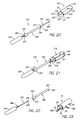
- Figs. 20-22 show a preferred embodiment of a collapsible retractor 210 with an accompanying collapsing tool 240.
- the retractor 210 includes a tube or elongate member 212 having an arcuate or "C" shaped cross-section and fabricated from a substantially resilient, semi-rigid material, preferably biased to resume its "C" shape.
- the tube 212 may be fabricated by extrusion from PVC material, possibly including an endoscope channel (not shown) simultaneously extruded and integrally formed along the inner surface 234 of the tube 212.
- the tube 212 may be extruded in its arcuate form, or a cylindrical tube (not shown) may be formed, with a lower portion of the periphery of the tube subsequently removed, such as by cutting longitudinally along the tube.
- One or more flexible wires, strings or cables may be attached to the tube 212 for collapsing the tube 212 to facilitate insertion of the retractor 210 into an anatomic space (not shown) and removal from the space.
- a pair of wires 230 and 231 are attached across the passage 218 above the longitudinal edges 222 near the proximal end 214 and the distal end 216 of the tube 212 respectively.
- the wires 230, 231 may be fused or bonded to the inner surface 234 of the tube 212, or may extend through holes (not shown) where they may be knotted or otherwise fastened to the outside of the tube 212.
- the wires 230, 231 may be fabricated from any suitable inelastic but flexible material, such as stainless steel, nitinol or plastic. Thus, when the wires 230, 231 are tensioned, that is are directed axially towards or away from one another, the edges 222 are drawn together, thereby reducing the profile of the retractor 210.
- a collapsing tool 240 may be provided, preferably including only three parts, namely a shaft 242, a tube 250, and a spring 260.
- the parts may be fabricated from conventional materials, such as any suitable medical quality metal or plastic, that are sufficiently durable to allow the tool 240 to be disassembled after use for cleaning and reassembled for subsequent reuse.
- the shaft 242 preferably is a substantially rigid elongate member having a notch 248, or alternatively a hook (not shown), adjacent its distal end 246, and having a proximal handle 244.
- the distal end 246 is rounded to minimize tissue trauma during use.
- the spring 260 is a conventional helical spring or similar resiliently compressible device that may be received over the shaft 242.
- the tool 240 may be provided without the spring 260, although the spring 260 is preferred for biasing the tool 240 to release a retractor 210 held thereon, as explained below.
- the tube 250 is a substantially rigid tubular member having a passage (not shown) extending longitudinally through it for slidably receiving the shaft 242 therein.
- the proximal end 252 includes an enlarged portion or grip 253 to facilitate holding the tube 250 and to abut the spring 260.
- the tube 250 also includes a hook 256 on its distal end 254 that points proximally, thereby defining a receiving region 258.
- the spring 260 is placed on the shaft 242, and the distal end 246 of the shaft 242 is inserted into the proximal end 252 of the passage in the tube 250 until the shaft 242 extends substantially beyond the distal end 254 of the tube 242.
- the tool 240 is in a first position for receiving a retractor 210 thereon ( Fig. 20 ).
- the respective lengths of the shaft 242 and tube 250 are such that the resulting distance between the notch 248 and hook 256 corresponds substantially to the distance between the wires 230 and 231 on the retractor 210.
- the wires 231 and 230 may be received respectively in the notch 248 and the hook 256.
- the grip 253 may then be pulled proximally towards the handle 244, compressing the spring 260, and increasing the distance between the notch 248 and the hook 256.
- the resulting tension draws the edges 222 of the retractor 210 together, thereby reducing the profile of the retractor 210 ( Fig. 21 ).
- the resulting collapsed condition of the retractor 210 thus facilitates insertion and removal of the retractor 210.
- the collapsed retractor 210 is deployed by releasing the grip 253.
- the spring 260 directs the hook 254 distally, the wires are released, allowing the retractor 210 to resiliently resume its "C" shape and consequently hold the anatomic space substantially open.
- the tool 240 may then be withdrawn from the space, and the desired endoscopic procedure performed.
- the retractor 210 may be removed by reinserting the tool 240 into the space until it receives the wires 230 and 231 once again, whereupon the grip 253 may be drawn proximally, drawing the wires and collapsing the retractor 210 for removal.
- the retractor 210 may be fabricated from a semi-rigid wire mesh, such as a material similar to those used for coronary stents. The retractor 210 would then be capable of maintaining a collapsed condition, having a reduced profile for facilitating insertion, and an expanded condition such as the "C" shape described above, for holding an anatomic space open.
- the tool 240 may also include an inflatable balloon (not shown) on the shaft 242, and the retractor 210 may be placed on the shaft 242 over the balloon. The retractor 210 may be held on the shaft 242 by the wires 230, 231 received within the notch 248 and hook 256 on the tool as described above.
- the retractor 210 may be provided without wires, and the notch 248 and hook 254 may engage the wire mesh of the retractor 210 directly.
- the distal end 246 of the tool with the retractor 210 thereon may be inserted into a dissected space to a desired location.
- the retractor 210 may then be deployed, for example, by releasing the retractor 210 and inflating the balloon, thereby expanding the retractor 210 to its expanded condition.
- the tool may be removed until completion of the procedure within the space, whereupon the tool may be inserted into the passage 18 to remove the retractor 210.
- the notch 248 and hook 252 may engage the wires or the wire mesh directly to collapse the retractor 210 for removal.
- the retractor 210 maybe provided from a substantially rigid material, such as polycarbonate, eliminating the need for the wires 230 and 231.
- the tool 240 may be used to facilitate insertion and removal of the retractor 210 within a dissected space.
- the retractor 210 may include elongate openings (not shown) adjacent the proximal and distal ends 214, 216 for receiving the notch 248 and the hook 254.
- the notch 248 and the hook 254 may be oriented towards one another (not shown), thereby allowing the tool 240 to directly grab the ends 214, 216 of the retractor 210.
- the notch 248 and hook 254 may be inserted into the openings, and the grip 253 may be pulled proximally, increasing the distance between the notch 248 and the hook, and thereby gripping the retractor 210.
- the grip 253 may be pulled, the retractor 210 placed between the notch 248 and the hook 254, and the grip 253 released, allowing the notch 248 and the hook 254 to engage the distal and proximal ends 216, 214 respectively, thereby substantially grabbing the retractor 210.
- the distal end 246 of the tool 240 with the retractor 210 thereon may be inserted into an anatomic space, the retractor 210 may be released, and the tool 240 removed. After the procedure is completed, the tool 240 may be introduced into the passage 18, and the retractor 210 may be gripped again for removal.
- notch and hook (or alternatively, a first and second hook) to be slid distally and proximally in relation to one another.
- a notch or hook may be placed on the end of a rail and a hook may then be slidably mounted on the rail, such as on a substantially rigid shaft that has a length smaller than the length of the rail.
- the tool may include a locking mechanism or detents, such as a detachable hook or a cooperating tab and slot, to hold the notch and hook in a predetermined position, for example in the hold or release positions.
- any of the embodiments of the retractor described herein may also include a built-in light source (not shown) to illuminate the passage 18 and/or the working window 20 to enhance visualization.
- a retractor 10 may include one or more notches 25 extending up from the longitudinal edges 22 of the retractor 10.
- the notches 25 may extend along a region of the retractor 10 to better expose side branches extending laterally from the working window 20, such as a tributary vein 284 that may feed into a vein 282 being harvested, as shown.
- a principal feature of a retractor in accordance with the present invention is providing a self-supporting device capable of holding open an anatomic space for endoscopic surgery.
- Conventional methods may be used to create an incision and dissect an anatomic space, for example for endoscopic vein harvesting in a patient's leg.
- U.S. Patent No. 5,601,581, issued to Fogarty et al. discloses an apparatus and method suitable for dissecting an anatomic space.
- a section of a tissue structure for example a nerve or vein, especially the saphenous vein, is selected to be harvested.
- An incision is created at a location adjacent to one end of the selected structure, such as at the groin or knee.
- a tunneling instrument such as a blunt or soft-tipped dissector including an inflatable balloon thereon, is inserted into the incision and advanced along between tissue layers to identify the selected structure, and then is advanced along the anterior surface of the structure to create a small tunnel.
- the balloon is inflated to enlarge the tunnel and may be used to dissect fat and skin overlying the structure to develop a tunnel of a desired size.
- the balloon is then deflated, and the tunneling instrument is removed from the dissected space.
- a retractor in accordance with the present invention may then be inserted into the incision and directed along the dissected space while orienting the longitudinal working window towards the structure.
- An endoscope may be inserted into the passage and retained by the channel member of the retractor, thereby allowing visualization of the space and along the working window.
- the arcuate shape of the described embodiments allow the tissues anterior to the surgical site, such as the tissues anterior to the saphenous vein, to be held up and away from the site without needing external support.
- the longitudinal edges of the arcuate retractor abut the subcutaneous tissues adjacent the anterior surface of the selected structure, the longitudinal working window defined by the edges providing access along a desired length, for example of the vein being harvested.
- Surgical instruments may be introduced into the incision and directed along the passage defined by the retractor to any point along the length of the working window without having to relocate the retractor, for example to perform an endoscopic vein harvesting procedure.
- a pivotable channel member is provided on the retractor, the endoscope may be pivoted, as well as being directed axially, to observe the procedure being performed within the space.
- a retractor in accordance with the present invention may allow a vein, nerve or similar elongate tissue structure to be harvested without having to relocate the retractor during the procedure.
Description
- The present invention relates generally to surgical retractors, and more particularly to vascular retractors that are self-supporting and provide a longitudinal working window for endoscopic vascular harvesting procedures.
- Numerous surgical procedures have been developed to replace arteries that have become blocked by disease. For example, in coronary bypass surgery, a vein may be harvested from elsewhere in the body and grafted into place between the aorta and the coronary artery. It is generally preferred to use a vein taken from the patient undergoing the surgery, as the patient is a ready source of suitable veins that will not be rejected by the body after grafting. In particular, the saphenous vein in the leg is often used for this procedure. The saphenous vein is typically 3-5 mm in diameter, comparable in size to the coronary arteries. Furthermore, the venous system of the legs is sufficiently redundant that the saphenous vein may be removed and the remaining veins in the leg will continue to provide adequate return blood flow. Alternatively, the cephalic vein in the arm may sometimes be used as well.
- Traditionally, to harvest the saphenous vein, an open surgical procedure has been used to expose and remove the vein from the leg. A series of incisions with skin bridges (and sometimes a long single incision) is made from the groin to the knee or to the ankle. Once the vein is exposed, the surgeon dissects the vein from the surrounding tissues, lifts the vein from the tissues, and divides and ligates the various tributary veins that feed into the saphenous vein. Once the vein is completely mobilized, the surgeon cuts the ends of the vein and removes it from the leg. The long incisions in the leg are closed, and the vein is prepared for implantation.
- More recently, vein harvesting has been accomplished using endoscopic procedures. One or more small incisions are made at selected target sites for providing access to the vein being harvested. For example, to harvest the saphenous vein, an incision may be made at the groin, at the knee, and/or at the ankle. A tunneling instrument, such as a blunt or soft-tipped dissector may be utilized to dissect a subcutaneous space along the anterior surface of the vein being harvested. Such instruments generally include a substantially transparent elongate member having a rounded distal end and a passage therein for receiving an endoscope, the endoscope providing visualization through the end and/or side walls of the dissector. The tunneling instrument is inserted into the incision and advanced or pushed along between tissue layers to identify the saphenous vein. The tip of the dissector is generally kept in contact with the vein and the dissector is advanced along the tissues, thereby creating a small tunnel along the anterior surface of the vein. An inflatable balloon may then be introduced into the tunnel (or alternatively provided in a collapsed condition on the tunneling instrument prior to insertion into the incision), and inflated to enlarge and further propagate the tunnel. The balloon may be used to dissect fat and skin overlying the vein and to enlarge the tunnel to an appropriate size.
- Once the desired length of vein is exposed and an appropriate tunnel developed, the balloon and/or dissector is removed, and a retractor, typically a wide flat shaft with a handle on its proximal end, is prepared. The retractor is inserted into the incision and directed along the dissected path over the section of vein to be harvested. The handle of the retractor may then be lifted away from the surface of the leg, creating a space under the shaft adjacent the vein.
- Surgical instruments, such as a vein harvesting hook, may then be inserted into the space to strip away tissues surrounding the vein, ligate tributary veins, and mobilize the vein. Typically, the retractor has substantially transparent walls and an endoscope is provided in a passage in the retractor, thereby allowing visualization during the harvesting procedure.
- Conventional retraction devices, such as those used in the vein harvesting procedure just described, often have limitations. For example, such retractors typically require external support to hold the retractor away from the surface of the vein and maintain the anatomic space. The surgeon may have to hold the handle on the retractor, preventing both hands from being free for the procedure or requiring an assistant. Alternatively, an external mechanical support may be provided to hold the retractor, but such a support may interfere with access to the operative site.
- Some retractors include a distal hood capable of maintaining a space thereunder. These hoods, however, only create a limited self-supported space, requiring that the retractor be moved when it is desired to work in a new location. Such retractors also generally require external support to provide a space along the retractor shaft between the incision and the hooded space.
- In addition, some retractors include a channel to direct an endoscope to the operative site. An endoscope inserted into such a conventional retractor, however, may not allow the surgeon to monitor the surgery as effectively as desired. For example, the walls of the retractor may cause glare or distortion impairing visualization of the vein. Further, although the endoscope may be moved axially within the channel in the retractor to view the section of vein, lateral movement may be limited without also moving the retractor itself. The proximal end of the endoscope may also partially obstruct the incision, and may impair introduction of surgical instruments into the anatomic space.
- United States patent
4,562,832 discloses a surgical retractor. The preamble ofclaim 1 is based on this document. - Accordingly, there is a need for a self-supporting retractor capable of holding open an anatomic space for endoscopic vascular procedures that does not require external support to maintain the space.
- In addition, there is a need for a retractor for holding open an anatomic space for endoscopic procedures that provides improved visualization within the space.
- The present invention provides a retractor according to
claim 1. - The present disclosure is directed to a retractor for holding open an anatomic space for performing endoscopic surgical procedures. Generally, the retractor comprises a substantially rigid elongate member, having proximal and distal ends, and having a tunnel or an arcuate, arch shaped or "C" shaped cross-section to hold the dissected space open. The distal end is preferably rounded or streamlined to facilitate insertion along a dissected space with minimal tissue trauma. The cross-section of the elongate member defines a passage therein within the "C" extending distally from the proximal end, and provides a longitudinal working window along the passage between the longitudinal edges of the arch, that is, below the edges of the "C". The elongate member may be fabricated from any metal or plastic material suitable for surgical devices, but preferably is formed from a substantially transparent plastic, such as polycarbonate, to facilitate illumination and/or visualization within the space.
- The elongate member may have a substantially uniform cross-section along its length, or it may be gradually tapered to suit particular applications where the anatomy of the patient requires large and small ends on the retractor. In addition, the elongate member may be a single formed piece, or it may include a plurality of cooperating segments. For example, the elongate member may include telescoping segments, allowing the length of the elongate member to be adjusted. Alternatively, and according to the claimed invention, the elongate member may include radially cooperating segments capable of being manipulated to increase or decrease the periphery of the arch, thereby adjusting the cross-sectional area of the anatomic space held open by the retractor.
- The elongate member need not have a uniform cross-section along its entire length. The edges of the "C" cross-section may only extend to a maximum periphery intermittently such that elsewhere along the length of the elongate member there is a greater degree of tissue exposure, hence greater working access to tissue. Preferably, the section of maximum peripheral extension is near the distal end of the elongate member. If so constructed, the self-retaining effect is gained for a substantial length adjacent the section of maximum peripheral extension.
- The retractor also may include a handle formed on or attached to the proximal end of the elongate member. A handle may be attached to the elongate member, for example substantially perpendicular to the longitudinal axis of the elongate member, to facilitate directing the retractor along the dissected space. In addition, the handle may include one or more finger grips pivotally attached to the proximal end of the elongate member to accommodate use with either the left or right hand of the surgeon performing the procedure.
- In a further aspect, the handle may have an ergonomic design. The ergonomic handle is designed to fit comfortably in one hand of a surgeon and provide the surgeon greater control of the retractor during insertion, placement, and removal. The ergonomic handle is adapted to receive a scope and may further include a receptacle for holding a scope light in a near vertical direction.
- Alternatively, a curved handle may be attached to or integrally formed on the proximal end, extending proximally therefrom and curving up and away from the passage defined by the elongate member. The handle may comprise an arch-shaped or curved proximal region that extends proximally from a straight distal region of the retractor. Such a curved handle or proximal region may hold open the incision accessing the dissected space, thereby facilitating insertion of the tools used to perform the intended procedure.
- In addition, the retractor may also include a channel for an endoscope, a light source, or similar visualization apparatus. The channel need not extend the full length of the retractor, and may even be a ring. The endoscope channel may be integrally formed along an inside surface of the elongate member. For example, the endoscope channel may be defined by a "C"-shaped member integrally formed along the top of the arch and extending distally from the proximal end.
- Alternatively, the endoscope channel may be pivotally attached to the elongate member. For example, a cylindrical sleeve, defining the endoscope channel therein, may be attached to the inside surface of the elongate member. The sleeve may include a tab extending therefrom that may be inserted into a similarly shaped hole or slot in the wall of the elongate member. The cooperating tab and hole frictionally engage one another, holding the sleeve in place. If the tab and hole are substantially round, they may also allow the sleeve, and consequently an endoscope inserted therein, to be pivoted about an axis defined by the tab and hole. Alternatively, the sleeve may be substantially permanently fixed to the elongate member, for example by force-fitting the tab into the hole, or by using suitable adhesives.
- The retractor may also include an enclosed distal end or hooded portion. A hooded portion may be integrally formed on the distal end of the elongate member or a hood may be formed from a separate component attached to the elongate member. The hooded portion substantially encloses the distal end of the elongate member and includes a rounded distal surface, thereby facilitating insertion along a dissected space with minimal tissue trauma. The hooded portion may have a width comparable to the width of the elongate member, or may have a larger width to provide a wider anatomic space, and therefore a wider working window within the hooded portion. The hooded portion may also be substantially transparent, allowing illumination and/or visualization distally therethrough to monitor insertion of the retractor along the dissected space.
- A retractor in accordance with the present disclosure may include other features as well. The retractor may include a light source built into the elongate member to provide illumination along the working window to aid in visualization. Alternatively, the proximal end may include a notched slot or other locking detents for holding a cable for a light source inserted into the passage. The proximal end may include a stand, such as a bipod, to help support the retractor and hold open the incision and/or the dissected space. The stand may be a concave-shaped balloon located at or near the proximal end or on the handle of the retractor. The inflatable stand is inflated upon insertion of the retractor into a portion of a patient's body. The inflatable stand rests on the patient thereby elevating and supporting the retractor. A proximal portion of the elongate member may include an elongate slot, for adjustably connecting the retractor to a support arch which may be attached to the patient adjacent the site of the incision.
- Thus, it is an object of the present invention to provide an improved retractor for endoscopic procedures.
- Additional objects and features of the present invention will become apparent from consideration of the following description taken in conjunction with the accompanying drawings.
-
-
Fig. 1 is a perspective view of a first oreferred embodiment of a vascular retractor in accordance with the present disclosure, with an endoscope received therein. -
Fig. 2 is a side view of the vascular retractor ofFig. 1 , without the endoscope. -
Figs. 3A and 3B are cross-sections of the retractor ofFig. 2 , taken along line 3-3, showing alternative embodiments of a channel for receiving an endoscope. -
Fig. 4 is a cross-section of the retractor ofFig. 2 , taken along line 4-4, showing circumferentially extended edges thereof. -
Fig. 5 is a perspective view of a second preferred embodiment of a retractor in accordance with the present disclosure, including a pivotable channel member for receiving an endoscope. -
Fig. 6 is a side view of the retractor ofFig. 5 . -
Fig. 7 is a cross-section of the retractor ofFig. 5 , taken along line 7-7. -
Fig. 8 is a top view of a retractor, including a locking mechanism for holding a light cable or like device. -
Fig. 9 is a side of view of another preferred embodiment of a retractor including a hooded portion and support legs. -
Fig. 10 is a side of a retractor with a hooded portion, and having an endoscope received therein. -
Fig. 11 is a perspective view of a retractor with a hooded portion, including a pivotable finger grip. -
Fig. 12 is a perspective view of an adjustable support device for holding a retractor in accordance with the present disclosure. -
Fig. 13 is an end view of the adjustable support device ofFig. 12 . -
Fig. 14 is a side view of the adjustable support device ofFig. 12 . -
Fig. 15 is a perspective view of an adjustable support device strapped to a patient's leg and holding a retractor and endoscope inserted into an incision in the patient's leg. -
Fig. 16 is a perspective view of a retractor including two slidably cooperating segments. -
Fig. 17 is a cross-sectional view of the retractor ofFig. 16 along line 17-17, showing the segments in a minimizing periphery position. -
Fig. 18 is a cross-sectional view of the retractor ofFig. 16 along line 17-17, showing the segments in a maximizing periphery position. -
Fig. 19 is a cross-sectional view of a retractor with a hooded portion which includes a lateral tunnel on the distal tip. -
Fig. 20 is a perspective view of a preferred embodiment of a collapsible retractor and a tool for collapsing the retractor. -
Fig. 21 is a perspective view of the tool ofFig. 20 holding the retractor in a collapsed condition. -
Fig. 22 is a perspective view of a partially disassembled tool for collapsing a retractor. -
Fig. 23 is a perspective view of a retractor in accordance with the present disclosure having extended notches for exposing a tributary vein. -
Fig. 24 is a perspective view of a retractor having an ergonomic handle in a accordance with the present invention. -
Fig. 25 is a perspective view of a retractor having an inflatable stand in accordance with the present disclosure. - Turning now to the drawings,
Figs. 1 and 2 show a first preferred embodiment of avascular retractor 10 in accordance with the present disclosure. Theretractor 10 includes anelongate member 12, ahandle 30, and anendoscope channel 40. Theelongate member 12 has aproximal end 14, adistal end 16, and an arcuate or "C" cross-section, as shown inFigs. 3A and 3B . The arcuate cross-section may define a portion of the periphery of a circle or an ellipse. Thedistal end 16 is preferably rounded or streamlined to minimize tissue trauma when theretractor 10 is directed along a dissected space in a patient (not shown). Theelongate member 12 defines apassage 18 therein extending distally from theproximal end 14, and includes a longitudinal workingwindow 20 along thepassage 18 between thelongitudinal edges 22 of theelongate member 12. Theelongate member 12 may be fabricated from any suitable metal or plastic material, but preferably is formed from a substantially transparent plastic, such as polycarbonate. Alternatively, the elongate member may be formed from a flexible or resilient, semi-rigid material, such as extruded polyvinyl chloride (PVC). - The
elongate member 12 includes circumferentially extended edges orcurved tabs 24 integrally formed along a portion of theedges 22 of theelongate member 12 and extending peripherally from theedges 22, thereby defining an extended periphery 26, as shown inFig. 4 . The extended edges 24 increase the anatomic space held open by theretractor 10 since the extended periphery further tents the anatomic space, particularly at the location adjacent the extended edges 24. Although theextended edges 24 are shown located on adistal region 28 of theelongate member 12, alternatively they may be located at any predetermined location along theelongate member 12. Furthermore, one or more additional sets of extended edges (not shown) may be provided in other regions of theelongate member 12 to further support the anatomic space being held open. - The
elongate member 12 also includes a curved proximal region or substantially rigidcurved handle 30 integrally formed therein. Thehandle 30 extends proximally from a straightdistal region 15 and curves up and away from thepassage 18, the curvedouter surface 32 being adapted to hold open or "tent" the incision (not shown) into which theretractor 10 is inserted, thereby facilitating introduction of surgical instruments for performing endoscopic procedures within the space held open by theretractor 10. - In addition, the
retractor 10 also includes achannel member 40 for receiving anendoscope 60, having an arbitrary length extending along a portion of theelongate member 12. Alternatively, a light source or other visualization apparatus (not shown) having a diameter similar to an endoscope may be received by thechannel member 40. As shown inFigs. 3A and 3B , thechannel member 40 is integrally formed along aninside surface 34 of theelongate member 12, thereby defining achannel 42 for receiving an endoscope (not shown inFigs. 3A and 3B). Fig. 3A shows thechannel member 40 as comprising acylindrical sleeve 44 defining thechannel 42, whileFig. 3B , shows a pair of curvedelongate tabs 46 together forming a "C"-shape and defining thechannel 42. Alternatively, as described below, a separate cylindrical sleeve or the like (not shown) may be pivotally attached to theelongate member 12 instead of the integral members shown. - An alternative configuration of the first preferred embodiment is shown in
Fig. 24 . Theretractor 10 ofFig. 24 is, in most respects, the same as theretractor 10 shown inFigs. 1-4 . Hence, throughout the description and figures, like reference numerals refer to like elements, and some elements are not explicitly described for all figures. Theretractor 10 ofFig. 24 has an innovative ergonomic handle 30a attached to, or integral with, the proximal end of theelongate member 12. - The ergonomic handle 30a may be made of any suitable material, including the materials appropriate for the
elongate member 12. The ergonomic handle 30a is shown in the preferred shape having a rounded distal side adapted to fit into the fingers of a hand gripping the handle 30a. This shape permits the surgeon to effectively grip theretractor 10 in one hand with enhanced maneuverability which affords precise motor control of theretractor 10 during insertion, placement, and removal into a body. The ergonomic handle 30a has anopening 41 through which a scope (not shown) or other visualization device may be inserted. The handle 30a further comprises areceptacle 21 adapted to receive and provide support for a scope light connector (not shown). The scope light connector may be secured by threads provided on thereceptacle 21 or by any other suitable fastening method. - Turning now to
Figs. 5 and 6 , a second preferred embodiment of aretractor 10 is shown. Theretractor 10 includes a substantially rigidelongate member 12 and achannel member 40. Theelongate member 12 has aproximal end 14 and adistal end 16, and has an arcuate or arch-shaped cross-section, as shown inFig. 7 . Theproximal end 14 may be held to manipulate theretractor 10 and may be rounded to facilitate gripping theretractor 10, although optionally, a handle (not shown) may also be provided on theproximal end 14. Thedistal end 16 is preferably rounded or streamlined to minimize tissue trauma when theretractor 10 is directed along a dissected space in a patient (not shown). Theelongate member 12 includes apassage 18 therein extending distally from theproximal end 14, defining a longitudinal workingwindow 20 along thepassage 18 between thelongitudinal edges 22 of theelongate member 12. Theelongate member 12 includes circumferentially extendededges 24 integrally formed along a portion of theedges 22 of theelongate member 12 and extending peripherally from theedges 22. - The
retractor 10 also includes achannel member 40 for receiving an endoscope (not shown). Thechannel member 40 includes acylindrical steeve 48, defining achannel 42 for receiving an endoscope, which is attachable to aninside surface 34 of theelongate member 12 by acylindrical tab 52 extending from thesleeve 48. Thetab 52 is inserted into a similarly shapedhole 36 in theelongate member 12. The cooperatingtab 52 andhole 36 frictionally engage one another, holding thesleeve 48 in place. Because thetab 52 andhole 36 are substantially round, thesleeve 48 may be pivoted about anaxis 54. Consequently, an endoscope inserted into thesleeve 48 may also be pivoted laterally, thereby providing an increased field of view. Alternatively, thesleeve 48 may be substantially permanently fixed to theelongate member 12, for example by force-fitting thetab 52 into thehole 36, or by using suitable adhesives. In the case of substantially permanent attachment, thetab 52 andhole 36 may have a number of possible configurations that sufficiently cooperate, for example an elongate tab and slot (not shown). - In addition, as shown in
Fig. 8 , theretractor 10 may include lockingdetents 70 or other locking mechanisms, for example, on theproximal end 14, to hold a cable for a light or other instrument (not shown) that may be inserted into the anatomic space held open by theretractor 10. Preferably, thedetents 70 are formed by anelongate slot 72 extending distally from theproximal end 14, and including a plurality of receivingregions 74 adapted to frictionally grip a cable inserted into theelongate slot 72. The detents may substantially fix the cable, minimizing obstruction within the anatomic space that could interfere with instruments inserted therein. - Turning now to
Figs. 9-11 , a third preferred embodiment of aretractor 10 in accordance with the present disclosure is shown. Similar to the previously described embodiments, theretractor 10 includes a substantially rigidelongate member 12 having aproximal end 14, adistal end 16, and an arcuate cross-section defining apassage 18. In this embodiment, theelongate member 12 also includes ahooded region 80 substantially enclosing thepassage 18 at thedistal end 16 of theelongate member 12. Preferably, thehooded region 80 is integrally formed on theelongate member 12, although alternatively, a separate hooded member (not shown) may be attached to theelongate member 12. - The
hooded region 80 has a substantially roundeddistal surface 82 to minimize tissue trauma when theretractor 10 is directed along a dissected space. In addition, thedistal surface 82 is preferably substantially transparent, thereby allowing illumination and/or visualization through thedistal surface 82 of thehooded region 80 of surrounding tissues when theretractor 10 is directed along the dissected space. - The
hooded region 80 also includes circumferentially extendededges 84 integrally formed along thelongitudinal edges 22 of theelongate member 12 and extending peripherally from theedges 22, thereby defining an extended periphery to increase the anatomic space held open by thehooded region 80. The extended edges 84 may extend all along theedge 86 of thedistal surface 82, thereby substantially enclosing thepassage 18 at thedistal end 16, or theedges 84 may be interrupted. For example, as inFig. 19 , a recessed region, such as the tunnel or notch 88, may be provided at thedistal end 16 of thehooded region 80 to accommodate a blood vessel or other tissue structure (not shown). Thetunnel 88 allows a structure therein to be accessed from within thehooded portion 80 without imposing an undesirable load directly onto the structure. Thehooded region 80 may have a width comparable to the other portions of theelongate member 12, or may have a larger width to create a wider working window (not shown) covered by thehooded region 80. - The
retractor 10 also includes afinger grip 92, to facilitate manipulation of theretractor 10 and/or theendoscope 60 received therein. Preferably, thefinger grip 92 includes a substantially rigidcurved handle 94 for being engaged by one or more fingers, although alternatively a ring or a straight handle (not shown) may also be provided. Thehandle 94 may be fixed to theproximal end 14 or, preferably, it may be pivotally attached thereto. For example, as shown inFig. 11 , thehandle 94 may be mounted on asleeve 96 that may rotate radially in relation to theelongate member 12, thereby allowing thefinger grip 92 to accommodate both a left hand and a right hand. Alternatively, theelongate member 12 andfinger grip 92 may include a cooperating slot and tab or other device (not shown) that allows rotation. - In addition, as shown in
Fig. 9 , theelongate member 12 may include additional support members or a stand, such as thelegs 90 which together provide a bipod, for elevating theproximal end 14 of theretractor 10, for example at a predetermined height above the surface of a patient's leg. Thelegs 90 are preferably detachable from theelongate member 12, such as by snaps or tabs, allowing thelegs 90 to be attached only when needed to tent the incision and facilitate the introduction of instruments into thepassage 18. - Referring to
Fig. 25 , analternative stand 300 for theretractor 10 is shown. Thestand 300 comprises aninflatable balloon 302 attached to theproximal end 14 of theelongate member 22 or, alternatively, attached to thehandle 32. Theballoon 302 may include a single inflatable chamber having two portions in which each portion constitutes one leg of a bipod, or theballoon 302 may include two separate inflatable chambers, each comprising one leg of the bipod. Theballoon 302 preferably forms a concave shape when inflated so that thestand 300 raises and supports the distal end of theretractor 10. The concave shape may be achieved by making theballoon 302 from a thin layer of sheet material attached to a thicker layer. When inflated, the thinner layer stretches more easily than the thick layer causing the balloon to become arched in a concave shape. The height of thestand 300 can be adjusted by controlling the inflation pressure. - An
inflation harness 304 is connected to theballoon 302 for inflating theballoon 302. The inflation harness is of the same type as described inus patent No. 5,928,730 . - The
stand 300 is operated by inflating the balloon(s) 302 after theretractor 10 has been inserted and placed into a patient's body. The balloon(s) 302 form legs which can rest on the patient's body or any other appropriate support structure. - To facilitate use of a retractor in accordance with the present invention, an adjustable support device may be provided to hold open or tent the incision into which the retractor is inserted and adjust the orientation of the retractor. For example,
Figs. 12-15 show asupport device 100 for use with aretractor 10 in accordance with the present invention. Thesupport device 100 generally includes afastening mechanism 110 for attaching the device, for example to a patient's leg 140 (Fig. 15 ), and asupport arch 120. Thefastening mechanism 110 includes a pair ofstraps 112 that may be wrapped around a leg, and a hook and eye (e.g. Velcro®)fastener 114 for securing thestraps 112. Alternatively, thefastening mechanism 110 may include ties, notch and pin belts, adhesive tapes or similar mechanical fasteners (not shown) that may securely hold thesupport arch 120 in a fixed relationship to the site of the surgical procedure. - The
support arch 120 is a substantially rigidarch member 122 attached to thefastening mechanism 110 at thebase 124 of thearch member 122, for example bytabs 126 that may be stitched, glued, riveted or otherwise fastened to thestraps 112. Thearch member 122 includes anelongate slot 128 extending radially along thearch member 122. Aconnector 130, such as a threaded rod with locking nuts, is provided that may travel in theslot 128. Theconnector 130 may be fixed in a desired position along theslot 128 by loosening, adjusting, and tightening theconnector 130. A retractor 10 (Fig. 15 ) may be attached to theconnector 130, for example by anelongate slot 78, which allows theretractor 10 to be adjusted axially in relation to theincision 150 into which theretractor 10 is introduced. - The
support device 100 may be provided from a variety of materials. For example, thestraps 112 may be formed from fabric or flexible plastic tape. Thesupport arch 120 may be made from substantially rigid materials, such as metal or engineered plastic, that provide sufficient support to hold a retractor attached thereto in a fixed position. - Thus, the
retractor 10 may be inserted into theincision 150, and connected to thesupport device 100, for example, to hold theincision 150 open to facilitate introduction of surgical instruments therein. As desired during a procedure, theconnector 130 may be loosened, allowing theretractor 10 to be adjusted proximally, distally, or laterally, and then may be fixed in a new position. - In addition to the single piece elongate member as described in the previous embodiments, the retractor may include multiple cooperating elongate members. For example, as shown in
Fig. 16 , the retractor 160 may include twoarcuate segments tabs 166 andslots 168. Thefirst segment 162 includes one or moreelongate slots 168, extending radially along thesegment 162. Thesecond segment 164 includes a tab or screw 166 that may be fixed in eachslot 168, but able to slidably travel along theslot 168. - As shown in
Figs. 17 and 18 , the retractor 160 may be provided with the segments in a first relative position minimizing theperiphery 170 defined by thesegments second segment 164 may be rotated to a position increasing theperiphery 170 to maximize thecross-sectional area 172 held open by the retractor 160. Theslots 168 may include alateral locking region 169 into which thetabs 166 may be received to lock thesegments - In another alternative embodiment, the retractor may be provided from a single piece of resilient, semi-rigid material, allowing the periphery to be minimized when the retractor is directed into and out of the anatomic space. For example, the longitudinal edges of the retractor may be rolled or compressed together, for example into a relatively small diameter cylinder, to facilitate the introduction of the retractor into a dissected space. Once in position, the elongate member may be released, and the edges may resiliently expand until the retractor assumes its arcuate or "C" shape, thereby holding the space open. Alternatively, only a distal-most portion of the retractor may be furnished from a resilient, semi-rigid material, that may be compressed to facilitate introduction of the retractor, while the remaining portion may be formed from a substantially rigid material as previously described.
- For example,
Figs. 20-22 show a preferred embodiment of acollapsible retractor 210 with an accompanying collapsingtool 240. Theretractor 210 includes a tube orelongate member 212 having an arcuate or "C" shaped cross-section and fabricated from a substantially resilient, semi-rigid material, preferably biased to resume its "C" shape. For example, thetube 212 may be fabricated by extrusion from PVC material, possibly including an endoscope channel (not shown) simultaneously extruded and integrally formed along theinner surface 234 of thetube 212. Thetube 212 may be extruded in its arcuate form, or a cylindrical tube (not shown) may be formed, with a lower portion of the periphery of the tube subsequently removed, such as by cutting longitudinally along the tube. - One or more flexible wires, strings or cables (shown, for example, as 230 and 231) may be attached to the
tube 212 for collapsing thetube 212 to facilitate insertion of theretractor 210 into an anatomic space (not shown) and removal from the space. Preferably, a pair ofwires longitudinal edges 222 near theproximal end 214 and thedistal end 216 of thetube 212 respectively. Thewires inner surface 234 of thetube 212, or may extend through holes (not shown) where they may be knotted or otherwise fastened to the outside of thetube 212. Thewires wires edges 222 are drawn together, thereby reducing the profile of theretractor 210. - To facilitate use of the collapsible aspect of the
retractor 210, a collapsingtool 240 may be provided, preferably including only three parts, namely ashaft 242, atube 250, and aspring 260. The parts may be fabricated from conventional materials, such as any suitable medical quality metal or plastic, that are sufficiently durable to allow thetool 240 to be disassembled after use for cleaning and reassembled for subsequent reuse. Theshaft 242 preferably is a substantially rigid elongate member having anotch 248, or alternatively a hook (not shown), adjacent itsdistal end 246, and having aproximal handle 244. Preferably, thedistal end 246 is rounded to minimize tissue trauma during use. - The
spring 260 is a conventional helical spring or similar resiliently compressible device that may be received over theshaft 242. Alternatively, thetool 240 may be provided without thespring 260, although thespring 260 is preferred for biasing thetool 240 to release aretractor 210 held thereon, as explained below. - The
tube 250 is a substantially rigid tubular member having a passage (not shown) extending longitudinally through it for slidably receiving theshaft 242 therein. Theproximal end 252 includes an enlarged portion orgrip 253 to facilitate holding thetube 250 and to abut thespring 260. Thetube 250 also includes ahook 256 on itsdistal end 254 that points proximally, thereby defining a receivingregion 258. - To assemble the collapsing
tool 240 prior to use, thespring 260 is placed on theshaft 242, and thedistal end 246 of theshaft 242 is inserted into theproximal end 252 of the passage in thetube 250 until theshaft 242 extends substantially beyond thedistal end 254 of thetube 242. When thespring 260 is engaged, but not compressed, between thehandle 244 and thegrip 253, thetool 240 is in a first position for receiving aretractor 210 thereon (Fig. 20 ). The respective lengths of theshaft 242 andtube 250 are such that the resulting distance between thenotch 248 andhook 256 corresponds substantially to the distance between thewires retractor 210. Thus, when thedistal end 246 of thetool 240 is directed into thepassage 18 of theretractor 210, thewires notch 248 and thehook 256. - The
grip 253 may then be pulled proximally towards thehandle 244, compressing thespring 260, and increasing the distance between thenotch 248 and thehook 256. As thewires edges 222 of theretractor 210 together, thereby reducing the profile of the retractor 210 (Fig. 21 ). The resulting collapsed condition of theretractor 210 thus facilitates insertion and removal of theretractor 210. - Once the
retractor 210 is delivered to a desired location within a dissected space, thecollapsed retractor 210 is deployed by releasing thegrip 253. As thespring 260 directs thehook 254 distally, the wires are released, allowing theretractor 210 to resiliently resume its "C" shape and consequently hold the anatomic space substantially open. Thetool 240 may then be withdrawn from the space, and the desired endoscopic procedure performed. Upon completion of the procedure, theretractor 210 may be removed by reinserting thetool 240 into the space until it receives thewires grip 253 may be drawn proximally, drawing the wires and collapsing theretractor 210 for removal. - In an alternative embodiment, the
retractor 210 may be fabricated from a semi-rigid wire mesh, such as a material similar to those used for coronary stents. Theretractor 210 would then be capable of maintaining a collapsed condition, having a reduced profile for facilitating insertion, and an expanded condition such as the "C" shape described above, for holding an anatomic space open. Thetool 240 may also include an inflatable balloon (not shown) on theshaft 242, and theretractor 210 may be placed on theshaft 242 over the balloon. Theretractor 210 may be held on theshaft 242 by thewires notch 248 and hook 256 on the tool as described above. Alternatively, theretractor 210 may be provided without wires, and thenotch 248 and hook 254 may engage the wire mesh of theretractor 210 directly. Thedistal end 246 of the tool with theretractor 210 thereon may be inserted into a dissected space to a desired location. Theretractor 210 may then be deployed, for example, by releasing theretractor 210 and inflating the balloon, thereby expanding theretractor 210 to its expanded condition. The tool may be removed until completion of the procedure within the space, whereupon the tool may be inserted into thepassage 18 to remove theretractor 210. Thenotch 248 and hook 252 may engage the wires or the wire mesh directly to collapse theretractor 210 for removal. - In a further alternative embodiment, the
retractor 210 maybe provided from a substantially rigid material, such as polycarbonate, eliminating the need for thewires tool 240 to collapse theretractor 210, thetool 240 may be used to facilitate insertion and removal of theretractor 210 within a dissected space. For example, theretractor 210 may include elongate openings (not shown) adjacent the proximal anddistal ends notch 248 and thehook 254. Alternatively, thenotch 248 and thehook 254 may be oriented towards one another (not shown), thereby allowing thetool 240 to directly grab theends retractor 210. Thenotch 248 and hook 254 may be inserted into the openings, and thegrip 253 may be pulled proximally, increasing the distance between thenotch 248 and the hook, and thereby gripping theretractor 210. Alternatively, if the ends 214, 216 are gripped directly, thegrip 253 may be pulled, theretractor 210 placed between thenotch 248 and thehook 254, and thegrip 253 released, allowing thenotch 248 and thehook 254 to engage the distal and proximal ends 216, 214 respectively, thereby substantially grabbing theretractor 210. Thedistal end 246 of thetool 240 with theretractor 210 thereon may be inserted into an anatomic space, theretractor 210 may be released, and thetool 240 removed. After the procedure is completed, thetool 240 may be introduced into thepassage 18, and theretractor 210 may be gripped again for removal. - Alternative configurations for the tool described herein may also be provided, if they allow the notch and hook (or alternatively, a first and second hook) to be slid distally and proximally in relation to one another. For example, a notch or hook may be placed on the end of a rail and a hook may then be slidably mounted on the rail, such as on a substantially rigid shaft that has a length smaller than the length of the rail. In addition, the tool may include a locking mechanism or detents, such as a detachable hook or a cooperating tab and slot, to hold the notch and hook in a predetermined position, for example in the hold or release positions.
- To facilitate performance of an endoscopic procedure, optionally, any of the embodiments of the retractor described herein may also include a built-in light source (not shown) to illuminate the
passage 18 and/or the workingwindow 20 to enhance visualization. In addition, as shown inFig. 23 , aretractor 10 may include one ormore notches 25 extending up from thelongitudinal edges 22 of theretractor 10. For example thenotches 25 may extend along a region of theretractor 10 to better expose side branches extending laterally from the workingwindow 20, such as atributary vein 284 that may feed into avein 282 being harvested, as shown. - A principal feature of a retractor in accordance with the present invention is providing a self-supporting device capable of holding open an anatomic space for endoscopic surgery. Conventional methods may be used to create an incision and dissect an anatomic space, for example for endoscopic vein harvesting in a patient's leg. For example,
U.S. Patent No. 5,601,581, issued to Fogarty et al. , discloses an apparatus and method suitable for dissecting an anatomic space. - To summarize, a section of a tissue structure, for example a nerve or vein, especially the saphenous vein, is selected to be harvested. An incision is created at a location adjacent to one end of the selected structure, such as at the groin or knee. A tunneling instrument, such as a blunt or soft-tipped dissector including an inflatable balloon thereon, is inserted into the incision and advanced along between tissue layers to identify the selected structure, and then is advanced along the anterior surface of the structure to create a small tunnel. The balloon is inflated to enlarge the tunnel and may be used to dissect fat and skin overlying the structure to develop a tunnel of a desired size. The balloon is then deflated, and the tunneling instrument is removed from the dissected space.
- A retractor in accordance with the present invention may then be inserted into the incision and directed along the dissected space while orienting the longitudinal working window towards the structure. An endoscope may be inserted into the passage and retained by the channel member of the retractor, thereby allowing visualization of the space and along the working window. The arcuate shape of the described embodiments allow the tissues anterior to the surgical site, such as the tissues anterior to the saphenous vein, to be held up and away from the site without needing external support. The longitudinal edges of the arcuate retractor abut the subcutaneous tissues adjacent the anterior surface of the selected structure, the longitudinal working window defined by the edges providing access along a desired length, for example of the vein being harvested. Surgical instruments may be introduced into the incision and directed along the passage defined by the retractor to any point along the length of the working window without having to relocate the retractor, for example to perform an endoscopic vein harvesting procedure. If a pivotable channel member is provided on the retractor, the endoscope may be pivoted, as well as being directed axially, to observe the procedure being performed within the space. Thus, a retractor in accordance with the present invention may allow a vein, nerve or similar elongate tissue structure to be harvested without having to relocate the retractor during the procedure.
Claims (8)
- A retractor (160) for holding open an anatomic space developed in a patient for performing an endoscopic procedure therein, said retractor characterised by comprising:a substantially rigid first elongate member (162) having proximal and distal ends (14, 16), said first elongate member having an arcuate cross-section partially defining a periphery of said retractor;a substantially rigid second elongate member (164) having proximal and distal ends (14, 16), said substantially rigid elongate second member slidably attached to said first elongate member, said second elongate member having an arcuate cross-section further defining the periphery of said retractor;wherein said second member may slide rotationally in relation to said first elongate member between first and second positions, thereby decreasing or increasing said periphery of said retractor, and
an ergonomic handle (94) located at said proximal end of said first elongate member. - The retractor of claim 1 wherein said first and second elongate members include a cooperating slot and tab (166, 168) for slidably attaching said second elongate member to said first elongate member.
- The retractor of claim 1 or 2 wherein said first and second elongate members provide a substantially rigid elongate member comprising an inside surface, said retractor comprising a channel on said inside surface and extending distally along a portion thereof, said channel comprising a "C"-shaped channel defining a passage therein for slidably receiving an endoscope.
- The retractor of any preceding claim wherein said first and second elongate members provide a substantially rigid elongate member having proximal and distal ends, wherein said distal end includes a substantially rounded distal end to facilitate insertion of said retractor into a dissected space in a patient.
- The retractor of any preceding claim wherein said first and second elongate members provide a substantially rigid elongate member wherein a distal region of said elongate member includes a hood enclosing said passage at said distal end,
wherein said hood is substantially transparent, thereby allowing visualization of tissues through said hood when said retractor is directed along a dissected space in a patient. - The retractor of any preceding claim wherein said first and second elongate members provide a substantially rigid elongate member wherein said elongate member has a tapered cross-section between said proximal and distal ends.
- The retractor of any preceding claim wherein said retractor is made of substantially transparent plastic.
- The retractor of any preceding claim wherein said first and second elongate members provide a substantially rigid elongate member having proximal and distal ends wherein said elongate member includes a finger grip attached to said proximal end for facilitating directing said elongate member during insertion into an anatomic space,
wherein said finger grip is rotationally attached to said proximal end, thereby facilitating gripping of said proximal end with either hand.
Applications Claiming Priority (3)
| Application Number | Priority Date | Filing Date | Title |
|---|---|---|---|
| US925967 | 1997-09-09 | ||
| US08/925,967 US5913818A (en) | 1997-06-02 | 1997-09-09 | Vascular retractor |
| PCT/US1998/017574 WO1999012477A1 (en) | 1997-09-09 | 1998-08-26 | Vascular retractor |
Publications (3)
| Publication Number | Publication Date |
|---|---|
| EP1011467A1 EP1011467A1 (en) | 2000-06-28 |
| EP1011467A4 EP1011467A4 (en) | 2007-06-13 |
| EP1011467B1 true EP1011467B1 (en) | 2008-08-06 |
Family
ID=25452507
Family Applications (1)
| Application Number | Title | Priority Date | Filing Date |
|---|---|---|---|
| EP98943375A Expired - Lifetime EP1011467B1 (en) | 1997-09-09 | 1998-08-26 | Vascular retractor |
Country Status (5)
| Country | Link |
|---|---|
| US (2) | US5913818A (en) |
| EP (1) | EP1011467B1 (en) |
| DE (1) | DE69839843D1 (en) |
| ES (1) | ES2308812T3 (en) |
| WO (1) | WO1999012477A1 (en) |
Families Citing this family (90)
| Publication number | Priority date | Publication date | Assignee | Title |
|---|---|---|---|---|
| US6196968B1 (en) * | 1997-06-02 | 2001-03-06 | General Surgical Innovations, Inc. | Direct vision subcutaneous tissue retractor and method for use |
| US5913818A (en) * | 1997-06-02 | 1999-06-22 | General Surgical Innovations, Inc. | Vascular retractor |
| US6200263B1 (en) | 1998-01-23 | 2001-03-13 | United States Surgical Corporation | Surgical instrument holder |
| US6059802A (en) | 1998-02-27 | 2000-05-09 | Cardiothoracic Systems, Inc. | Dissecting retractor for harvesting vessels |
| US6228025B1 (en) | 1998-05-01 | 2001-05-08 | Genzyme Corporation | Illuminated saphenous vein retractor |
| DE19827360C2 (en) * | 1998-06-19 | 2000-05-31 | Storz Karl Gmbh & Co Kg | Medical instrument for endoscopic removal of the saphenous vein |
| US6648815B2 (en) | 1998-06-19 | 2003-11-18 | Karl Storz Gmbh & Co. Kg | Medical instrument and method for endoscopic removal of the saphenous vein |
| US6159179A (en) | 1999-03-12 | 2000-12-12 | Simonson; Robert E. | Cannula and sizing and insertion method |
| AU5031900A (en) * | 1999-05-21 | 2000-12-12 | Cardiothoracic Systems, Inc. | Refractor apparatus for use in harvesting mammary arteries during heart by-pass surgery |
| US6585727B1 (en) | 1999-10-22 | 2003-07-01 | Genzyme Corporation | Surgical instrument light source and surgical illumination method |
| US6428473B1 (en) | 2000-02-18 | 2002-08-06 | Genzyme Corporation | Illuminated rectal retractor |
| US6497654B1 (en) | 2000-02-18 | 2002-12-24 | Genzyme Corporation | Illuminated rectal retractor |
| WO2002002022A1 (en) | 2000-06-30 | 2002-01-10 | Stephen Ritland | Polyaxial connection device and method |
| US6554768B1 (en) | 2000-09-05 | 2003-04-29 | Genzyme Corporation | Illuminated deep pelvic retractor |
| US7166073B2 (en) | 2000-09-29 | 2007-01-23 | Stephen Ritland | Method and device for microsurgical intermuscular spinal surgery |
| US6692434B2 (en) * | 2000-09-29 | 2004-02-17 | Stephen Ritland | Method and device for retractor for microsurgical intermuscular lumbar arthrodesis |
| US6929606B2 (en) * | 2001-01-29 | 2005-08-16 | Depuy Spine, Inc. | Retractor and method for spinal pedicle screw placement |
| CA2435718A1 (en) * | 2001-01-29 | 2002-08-08 | Stephen Ritland | Retractor and method for spinal pedicle screw placement |
| DE60236726D1 (en) | 2001-06-26 | 2010-07-29 | Tyco Healthcare | |
| US8328808B2 (en) * | 2001-06-27 | 2012-12-11 | Biomet, C.V. | Minimally invasive orthopaedic apparatus and methods |
| US7137949B2 (en) * | 2001-07-13 | 2006-11-21 | United States Surgical Corporation | Surgical instrument |
| WO2003013367A2 (en) | 2001-08-10 | 2003-02-20 | General Surgical Innovations Inc. | Vascular harvesting tool and methods |
| AU2002355439B2 (en) * | 2001-08-10 | 2007-11-15 | Covidien Lp | Retractor for vasculary surgery, and methods of use |
| EP2428171B1 (en) * | 2001-09-24 | 2014-02-19 | Applied Medical Resources Corporation | Bladeless Obturator |
| US6740102B2 (en) * | 2001-09-28 | 2004-05-25 | Ethicon, Inc. | Vessel harvesting retractor with bilateral electrosurgical ligation |
| JP4249021B2 (en) | 2001-09-28 | 2009-04-02 | リットランド、ステファン | Connecting rod for screw or hook multi-axis system and method of use |
| US6991632B2 (en) | 2001-09-28 | 2006-01-31 | Stephen Ritland | Adjustable rod and connector device and method of use |
| US7008431B2 (en) | 2001-10-30 | 2006-03-07 | Depuy Spine, Inc. | Configured and sized cannula |
| US6916330B2 (en) * | 2001-10-30 | 2005-07-12 | Depuy Spine, Inc. | Non cannulated dilators |
| US7824410B2 (en) * | 2001-10-30 | 2010-11-02 | Depuy Spine, Inc. | Instruments and methods for minimally invasive spine surgery |
| ATE476930T1 (en) | 2002-02-20 | 2010-08-15 | Stephen Ritland | DEVICE FOR CONNECTING HAND SCREWS |
| US20030187431A1 (en) * | 2002-03-29 | 2003-10-02 | Simonson Robert E. | Apparatus and method for targeting for surgical procedures |
| US6966910B2 (en) | 2002-04-05 | 2005-11-22 | Stephen Ritland | Dynamic fixation device and method of use |
| WO2003094699A2 (en) | 2002-05-08 | 2003-11-20 | Stephen Ritland | Dynamic fixation device and method of use |
| US7131973B2 (en) * | 2002-05-16 | 2006-11-07 | Boston Scientific Scimed, Inc. | Bone anchor implantation device |
| JP2005525860A (en) | 2002-05-16 | 2005-09-02 | アプライド メディカル リソーシーズ コーポレイション | An obturator with a conical tip |
| US6805666B2 (en) * | 2002-05-23 | 2004-10-19 | Donna D. Holland | Pivotal and illuminated saphenous vein retractor with tapered design |
| US20050182301A1 (en) * | 2003-01-31 | 2005-08-18 | Zimmer Technology, Inc. | Lit retractor |
| US7371213B2 (en) * | 2003-01-31 | 2008-05-13 | Zimmer Technology, Inc. | Lit retractor |
| US8262571B2 (en) | 2003-05-22 | 2012-09-11 | Stephen Ritland | Intermuscular guide for retractor insertion and method of use |
| US7138316B2 (en) * | 2003-09-23 | 2006-11-21 | Intel Corporation | Semiconductor channel on insulator structure |
| EP2545860B1 (en) | 2003-10-03 | 2014-02-12 | Applied Medical Resources Corporation | Bladeless optical obturator |
| US20050096670A1 (en) * | 2003-10-31 | 2005-05-05 | Parris Wellman | Surgical end effector |
| US20050096646A1 (en) * | 2003-10-31 | 2005-05-05 | Parris Wellman | Surgical system for retracting and severing tissue |
| US20050096671A1 (en) * | 2003-10-31 | 2005-05-05 | Parris Wellman | Control mechanism for a surgical instrument |
| US20050096645A1 (en) * | 2003-10-31 | 2005-05-05 | Parris Wellman | Multitool surgical device |
| US7314479B2 (en) * | 2003-10-31 | 2008-01-01 | Parris Wellman | Space-creating retractor with vessel manipulator |
| US20060173474A1 (en) * | 2003-10-31 | 2006-08-03 | Parris Wellman | Surgical device having a track to guide an actuator |
| US7846171B2 (en) | 2004-05-27 | 2010-12-07 | C.R. Bard, Inc. | Method and apparatus for delivering a prosthetic fabric into a patient |
| EP1765197B1 (en) | 2004-06-29 | 2017-03-29 | Applied Medical Resources Corporation | Insufflating optical surgical instrument |
| US7909843B2 (en) * | 2004-06-30 | 2011-03-22 | Thompson Surgical Instruments, Inc. | Elongateable surgical port and dilator |
| US7621916B2 (en) * | 2004-11-18 | 2009-11-24 | Depuy Spine, Inc. | Cervical bone preparation tool and implant guide systems |
| GB0502772D0 (en) * | 2005-02-10 | 2005-03-16 | Medical Device Innovations Ltd | Endoscopic dissector |
| EP1906885B2 (en) | 2005-07-19 | 2019-01-16 | Warsaw Orthopedic, Inc. | Rod extension for extending fusion construct |
| DE602005013777D1 (en) * | 2005-08-24 | 2009-05-20 | Alberto Terrini | Tissue separator, in particular for removing the saphenous vein |
| US20070118119A1 (en) * | 2005-11-18 | 2007-05-24 | Zimmer Spine, Inc. | Methods and device for dynamic stabilization |
| US8409088B2 (en) | 2006-01-18 | 2013-04-02 | Invuity, Inc. | Retractor illumination system |
| US8262567B2 (en) | 2006-03-31 | 2012-09-11 | Insightra Medical, Inc. | Tissue retractor, tissue retractor kit and method of use thereof |
| US8047987B2 (en) * | 2006-05-26 | 2011-11-01 | Invuity, Inc. | Blade insert illuminator |
| US7959564B2 (en) | 2006-07-08 | 2011-06-14 | Stephen Ritland | Pedicle seeker and retractor, and methods of use |
| US8517977B2 (en) | 2006-10-06 | 2013-08-27 | Applied Medical Resources Corporation | Visual insufflation port |
| US8029544B2 (en) * | 2007-01-02 | 2011-10-04 | Zimmer Spine, Inc. | Spine stiffening device |
| US8852089B2 (en) * | 2007-08-01 | 2014-10-07 | Warsaw Orthopedic, Inc. | Instrumentation for tissue retraction |
| US8088066B2 (en) | 2007-10-24 | 2012-01-03 | Invuity, Inc. | Blade insert illuminator |
| AU2008340311B2 (en) * | 2007-12-21 | 2014-12-18 | Smith & Nephew, Inc. | Cannula |
| US9381007B2 (en) | 2008-01-09 | 2016-07-05 | Specialty Surgical Instrumentation Inc. | Tissue retractor and method of use thereof |
| EP2837345B1 (en) | 2008-01-25 | 2016-10-05 | Applied Medical Resources Corporation | Insufflating access system |
| US11382711B2 (en) | 2008-08-13 | 2022-07-12 | Invuity, Inc. | Cyclo olefin polymer and copolymer medical devices |
| EP2328487B1 (en) | 2008-09-29 | 2018-04-18 | Applied Medical Resources Corporation | First-entry trocar system |
| US9339264B2 (en) | 2010-10-01 | 2016-05-17 | Cook Medical Technologies Llc | Port access visualization platform |
| US9232962B2 (en) * | 2009-10-02 | 2016-01-12 | Cook Medical Technologies Llc | Apparatus for single port access |
| US20110172688A1 (en) * | 2010-01-11 | 2011-07-14 | Tyco Healthcare Group Lp | Conduit Harvesting Instrument and Method |
| WO2012088501A2 (en) | 2010-12-23 | 2012-06-28 | Mayo Foundation For Medical Education And Research | Vessel dissection and harvesting apparatus, systems and methods |
| JP6066428B2 (en) | 2011-05-02 | 2017-01-25 | アプライド メディカル リソーシーズ コーポレイション | Low profile surgical universal access port |
| US9642606B2 (en) | 2012-06-27 | 2017-05-09 | Camplex, Inc. | Surgical visualization system |
| US8882662B2 (en) | 2012-06-27 | 2014-11-11 | Camplex, Inc. | Interface for viewing video from cameras on a surgical visualization system |
| WO2014189969A1 (en) | 2013-05-21 | 2014-11-27 | Camplex, Inc. | Surgical visualization systems |
| US10881286B2 (en) | 2013-09-20 | 2021-01-05 | Camplex, Inc. | Medical apparatus for use with a surgical tubular retractor |
| WO2015042460A1 (en) | 2013-09-20 | 2015-03-26 | Camplex, Inc. | Surgical visualization systems and displays |
| CN107072652B (en) * | 2014-06-18 | 2019-08-02 | 哈佛学院院长及董事 | Soft retractor |
| US10646210B2 (en) | 2014-10-14 | 2020-05-12 | Covidien Lp | Methods and devices for vein harvesting |
| US10575835B2 (en) | 2014-10-14 | 2020-03-03 | Covidien Lp | Methods and devices for vein harvesting |
| US10702353B2 (en) | 2014-12-05 | 2020-07-07 | Camplex, Inc. | Surgical visualizations systems and displays |
| CN104605901A (en) * | 2015-01-28 | 2015-05-13 | 上海交通大学医学院附属第九人民医院 | Pull hook for soft tissue channel |
| WO2016154589A1 (en) | 2015-03-25 | 2016-09-29 | Camplex, Inc. | Surgical visualization systems and displays |
| US10064611B2 (en) | 2015-07-22 | 2018-09-04 | Covidien Lp | Methods and devices for vein harvesting |
| WO2017091704A1 (en) | 2015-11-25 | 2017-06-01 | Camplex, Inc. | Surgical visualization systems and displays |
| WO2018208691A1 (en) | 2017-05-08 | 2018-11-15 | Camplex, Inc. | Variable light source |
| US11547466B2 (en) | 2018-06-20 | 2023-01-10 | Covidien Lp | Visualization devices and methods for use in surgical procedures |
| US11826036B2 (en) | 2021-12-03 | 2023-11-28 | Lsi Solutions, Inc. | Epigastric retractor |
Family Cites Families (29)
| Publication number | Priority date | Publication date | Assignee | Title |
|---|---|---|---|---|
| US2575253A (en) * | 1949-05-16 | 1951-11-13 | Joseph F Bicek | Vaginal speculum |
| US2829649A (en) * | 1956-01-17 | 1958-04-08 | Robert J Glenner | Hemostat-retractor |
| US2821190A (en) * | 1956-04-20 | 1958-01-28 | John S Chase | Catheterizing endoscope |
| US3638973A (en) * | 1969-06-04 | 1972-02-01 | Charles Ellis Poletti | Joint means for use in work supporting arm |
| US3626471A (en) * | 1969-10-13 | 1971-12-07 | Robert E Florin | Illuminated suction brain retractor |
| US3651800A (en) * | 1970-05-15 | 1972-03-28 | James L Wilbanks | Surgical instrument |
| CA999196A (en) * | 1974-08-12 | 1976-11-02 | Mcanally, Raymond H. | Multipurpose vaginal and cervical device |
| US4232660A (en) * | 1979-03-26 | 1980-11-11 | Coles Robert L | Winged irrigating surgical retractor |
| US4447227A (en) * | 1982-06-09 | 1984-05-08 | Endoscopy Surgical Systems, Inc. | Multi-purpose medical devices |
| US4562832A (en) * | 1984-01-21 | 1986-01-07 | Wilder Joseph R | Medical instrument and light pipe illumination assembly |
| US4686972A (en) * | 1986-04-30 | 1987-08-18 | Kurland Kenneth Z | Surgical deflector and drilling guide |
| US4683879A (en) * | 1986-10-20 | 1987-08-04 | Tudor Williams R | Dual function connector for use with endotracheal apparatus |
| US4807593A (en) * | 1987-05-08 | 1989-02-28 | Olympus Optical Co. Ltd. | Endoscope guide tube |
| FR2662929A1 (en) * | 1990-06-08 | 1991-12-13 | Berlinski Michel | Surgical instrument of the retractor or vaginal retractor type |
| US5379759A (en) * | 1991-02-04 | 1995-01-10 | Sewell, Jr.; Frank K. | Retractor for endoscopic surgery |
| US5370134A (en) * | 1991-05-29 | 1994-12-06 | Orgin Medsystems, Inc. | Method and apparatus for body structure manipulation and dissection |
| JPH0642889B2 (en) * | 1992-07-11 | 1994-06-08 | 日新器械株式会社 | Retractor used during surgery |
| US5337732A (en) * | 1992-09-16 | 1994-08-16 | Cedars-Sinai Medical Center | Robotic endoscopy |
| US5373840A (en) * | 1992-10-02 | 1994-12-20 | Knighton; David R. | Endoscope and method for vein removal |
| US5431153A (en) * | 1993-06-11 | 1995-07-11 | Lee; Hans | Surgical apparatus for assisting in the release of the carpal tunnel |
| FR2726993B1 (en) * | 1994-11-18 | 1997-04-25 | Sgro Jean Claude | SINGLE-USE INFLATABLE DEVICE FOR SPREADING ANATOMIC TISSUES ESPECIALLY IN COELIOSCOPIC SURGERY AND ITS APPLICATION EQUIPMENT |
| US5759150A (en) * | 1995-07-07 | 1998-06-02 | Olympus Optical Co., Ltd. | System for evulsing subcutaneous tissue |
| US5667480A (en) * | 1995-10-20 | 1997-09-16 | Ethicon Endo-Surgery, Inc. | Method and devices for endoscopic vessel harvesting |
| US5817013A (en) * | 1996-03-19 | 1998-10-06 | Enable Medical Corporation | Method and apparatus for the minimally invasive harvesting of a saphenous vein and the like |
| US5846187A (en) * | 1996-09-13 | 1998-12-08 | Genzyme Corporation | Redo sternotomy retractor |
| US5913818A (en) * | 1997-06-02 | 1999-06-22 | General Surgical Innovations, Inc. | Vascular retractor |
| US6033361A (en) * | 1997-06-02 | 2000-03-07 | General Surgical Innovations, Inc. | Vascular retractor |
| US5902315A (en) * | 1997-08-28 | 1999-05-11 | Ethicon Endo-Surgery, Inc. | Optical tissue dissector/retractor |
| US5922004A (en) * | 1997-08-28 | 1999-07-13 | Ethicon Endo-Surgery, Inc. | Method for performing optical tissue dissection/retraction |
-
1997
- 1997-09-09 US US08/925,967 patent/US5913818A/en not_active Expired - Lifetime
-
1998
- 1998-08-26 EP EP98943375A patent/EP1011467B1/en not_active Expired - Lifetime
- 1998-08-26 WO PCT/US1998/017574 patent/WO1999012477A1/en active Application Filing
- 1998-08-26 ES ES98943375T patent/ES2308812T3/en not_active Expired - Lifetime
- 1998-08-26 DE DE69839843T patent/DE69839843D1/en not_active Expired - Lifetime
-
1999
- 1999-04-26 US US09/299,693 patent/US6228024B1/en not_active Expired - Lifetime
Also Published As
| Publication number | Publication date |
|---|---|
| ES2308812T3 (en) | 2008-12-01 |
| EP1011467A1 (en) | 2000-06-28 |
| US5913818A (en) | 1999-06-22 |
| WO1999012477A9 (en) | 1999-06-17 |
| EP1011467A4 (en) | 2007-06-13 |
| US6228024B1 (en) | 2001-05-08 |
| WO1999012477A1 (en) | 1999-03-18 |
| DE69839843D1 (en) | 2008-09-18 |
Similar Documents
| Publication | Publication Date | Title |
|---|---|---|
| EP1011467B1 (en) | Vascular retractor | |
| EP0986329B1 (en) | Vascular retractor | |
| US6196968B1 (en) | Direct vision subcutaneous tissue retractor and method for use | |
| EP2156793B1 (en) | Apparatus for dissecting and retracting elongate structures | |
| EP1348379B1 (en) | Balloon loaded dissecting instruments | |
| US5954739A (en) | Method of dissecting tissue layers | |
| US5860997A (en) | Method of dissecting tissue layers | |
| US5163949A (en) | Fluid operated retractors | |
| JP3391824B2 (en) | Endoscope tissue manipulator | |
| US5938680A (en) | Devices and methods for harvesting vascular conduits | |
| US6602188B2 (en) | Surgical instrument and associated method | |
| AU2002355439B2 (en) | Retractor for vasculary surgery, and methods of use | |
| AU2002355439A1 (en) | Retractor for vasculary surgery, and methods of use | |
| EP1107701A1 (en) | Surgical instrument |
Legal Events
| Date | Code | Title | Description |
|---|---|---|---|
| PUAI | Public reference made under article 153(3) epc to a published international application that has entered the european phase |
Free format text: ORIGINAL CODE: 0009012 |
|
| 17P | Request for examination filed |
Effective date: 20000315 |
|
| AK | Designated contracting states |
Kind code of ref document: A1 Designated state(s): DE ES FR GB IT |
|
| A4 | Supplementary search report drawn up and despatched |
Effective date: 20070516 |
|
| 17Q | First examination report despatched |
Effective date: 20070530 |
|
| GRAP | Despatch of communication of intention to grant a patent |
Free format text: ORIGINAL CODE: EPIDOSNIGR1 |
|
| RTI1 | Title (correction) |
Free format text: VASCULAR RETRACTOR |
|
| GRAS | Grant fee paid |
Free format text: ORIGINAL CODE: EPIDOSNIGR3 |
|
| GRAA | (expected) grant |
Free format text: ORIGINAL CODE: 0009210 |
|
| AK | Designated contracting states |
Kind code of ref document: B1 Designated state(s): DE ES FR GB IT |
|
| REG | Reference to a national code |
Ref country code: GB Ref legal event code: FG4D |
|
| REF | Corresponds to: |
Ref document number: 69839843 Country of ref document: DE Date of ref document: 20080918 Kind code of ref document: P |
|
| REG | Reference to a national code |
Ref country code: ES Ref legal event code: FG2A Ref document number: 2308812 Country of ref document: ES Kind code of ref document: T3 |
|
| PLBE | No opposition filed within time limit |
Free format text: ORIGINAL CODE: 0009261 |
|
| STAA | Information on the status of an ep patent application or granted ep patent |
Free format text: STATUS: NO OPPOSITION FILED WITHIN TIME LIMIT |
|
| 26N | No opposition filed |
Effective date: 20090507 |
|
| PGFP | Annual fee paid to national office [announced via postgrant information from national office to epo] |
Ref country code: ES Payment date: 20110826 Year of fee payment: 14 |
|
| PGFP | Annual fee paid to national office [announced via postgrant information from national office to epo] |
Ref country code: IT Payment date: 20110824 Year of fee payment: 14 |
|
| PG25 | Lapsed in a contracting state [announced via postgrant information from national office to epo] |
Ref country code: IT Free format text: LAPSE BECAUSE OF NON-PAYMENT OF DUE FEES Effective date: 20120826 |
|
| REG | Reference to a national code |
Ref country code: ES Ref legal event code: FD2A Effective date: 20131021 |
|
| PG25 | Lapsed in a contracting state [announced via postgrant information from national office to epo] |
Ref country code: ES Free format text: LAPSE BECAUSE OF NON-PAYMENT OF DUE FEES Effective date: 20120827 |
|
| REG | Reference to a national code |
Ref country code: FR Ref legal event code: PLFP Year of fee payment: 19 |
|
| PGFP | Annual fee paid to national office [announced via postgrant information from national office to epo] |
Ref country code: GB Payment date: 20160726 Year of fee payment: 19 Ref country code: DE Payment date: 20160721 Year of fee payment: 19 |
|
| PGFP | Annual fee paid to national office [announced via postgrant information from national office to epo] |
Ref country code: FR Payment date: 20160720 Year of fee payment: 19 |
|
| REG | Reference to a national code |
Ref country code: DE Ref legal event code: R119 Ref document number: 69839843 Country of ref document: DE |
|
| GBPC | Gb: european patent ceased through non-payment of renewal fee |
Effective date: 20170826 |
|
| REG | Reference to a national code |
Ref country code: FR Ref legal event code: ST Effective date: 20180430 |
|
| PG25 | Lapsed in a contracting state [announced via postgrant information from national office to epo] |
Ref country code: GB Free format text: LAPSE BECAUSE OF NON-PAYMENT OF DUE FEES Effective date: 20170826 Ref country code: DE Free format text: LAPSE BECAUSE OF NON-PAYMENT OF DUE FEES Effective date: 20180301 |
|
| PG25 | Lapsed in a contracting state [announced via postgrant information from national office to epo] |
Ref country code: FR Free format text: LAPSE BECAUSE OF NON-PAYMENT OF DUE FEES Effective date: 20170831 |