EP1013366A2 - Keyless chuck - Google Patents
Keyless chuck Download PDFInfo
- Publication number
- EP1013366A2 EP1013366A2 EP00200430A EP00200430A EP1013366A2 EP 1013366 A2 EP1013366 A2 EP 1013366A2 EP 00200430 A EP00200430 A EP 00200430A EP 00200430 A EP00200430 A EP 00200430A EP 1013366 A2 EP1013366 A2 EP 1013366A2
- Authority
- EP
- European Patent Office
- Prior art keywords
- sleeve
- chuck
- nut
- body member
- manual
- Prior art date
- Legal status (The legal status is an assumption and is not a legal conclusion. Google has not performed a legal analysis and makes no representation as to the accuracy of the status listed.)
- Granted
Links
Images


Classifications
-
- B—PERFORMING OPERATIONS; TRANSPORTING
- B23—MACHINE TOOLS; METAL-WORKING NOT OTHERWISE PROVIDED FOR
- B23B—TURNING; BORING
- B23B31/00—Chucks; Expansion mandrels; Adaptations thereof for remote control
- B23B31/02—Chucks
- B23B31/10—Chucks characterised by the retaining or gripping devices or their immediate operating means
- B23B31/12—Chucks with simultaneously-acting jaws, whether or not also individually adjustable
- B23B31/1207—Chucks with simultaneously-acting jaws, whether or not also individually adjustable moving obliquely to the axis of the chuck in a plane containing this axis
- B23B31/1238—Jaws movement actuated by a nut with conical screw-thread
-
- B—PERFORMING OPERATIONS; TRANSPORTING
- B23—MACHINE TOOLS; METAL-WORKING NOT OTHERWISE PROVIDED FOR
- B23B—TURNING; BORING
- B23B2231/00—Details of chucks, toolholder shanks or tool shanks
- B23B2231/38—Keyless chucks for hand tools
-
- B—PERFORMING OPERATIONS; TRANSPORTING
- B23—MACHINE TOOLS; METAL-WORKING NOT OTHERWISE PROVIDED FOR
- B23B—TURNING; BORING
- B23B2231/00—Details of chucks, toolholder shanks or tool shanks
- B23B2231/44—Nose pieces
-
- Y—GENERAL TAGGING OF NEW TECHNOLOGICAL DEVELOPMENTS; GENERAL TAGGING OF CROSS-SECTIONAL TECHNOLOGIES SPANNING OVER SEVERAL SECTIONS OF THE IPC; TECHNICAL SUBJECTS COVERED BY FORMER USPC CROSS-REFERENCE ART COLLECTIONS [XRACs] AND DIGESTS
- Y10—TECHNICAL SUBJECTS COVERED BY FORMER USPC
- Y10S—TECHNICAL SUBJECTS COVERED BY FORMER USPC CROSS-REFERENCE ART COLLECTIONS [XRACs] AND DIGESTS
- Y10S279/00—Chucks or sockets
- Y10S279/902—Keyless type socket
-
- Y—GENERAL TAGGING OF NEW TECHNOLOGICAL DEVELOPMENTS; GENERAL TAGGING OF CROSS-SECTIONAL TECHNOLOGIES SPANNING OVER SEVERAL SECTIONS OF THE IPC; TECHNICAL SUBJECTS COVERED BY FORMER USPC CROSS-REFERENCE ART COLLECTIONS [XRACs] AND DIGESTS
- Y10—TECHNICAL SUBJECTS COVERED BY FORMER USPC
- Y10T—TECHNICAL SUBJECTS COVERED BY FORMER US CLASSIFICATION
- Y10T279/00—Chucks or sockets
- Y10T279/17—Socket type
- Y10T279/17615—Obliquely guided reciprocating jaws
- Y10T279/17623—Threaded sleeve and jaw
- Y10T279/17632—Conical sleeve
Definitions
- the present invention relates generally to chucks for use with drills or with electric or pneumatic power drivers. More particularly, the present invention relates to a chuck of the keyless type which may be tightened or loosened by hand or by actuation of the driver motor.
- twist drills are the most common tools of such drivers
- the tools may also comprise screwdrivers, nut drivers, burrs, mounted grinding stones, and other cutting or abrading tools. Since the tools may have shanks of varying diameter or the cross section of the tool shank may be polygonal, the device is usually provided with a chuck which is adjustable over a relatively wide range. The chuck may be attached to the driver by a threaded or tapered bore.
- chucks have been developed in the art.
- three jaws spaced circumferentially approximately 120° apart from each other are constrained by angularly disposed passageways in a body attached onto the drive shaft of a driver and configured so that rotation of the body in one direction with respect to a constrained nut engaging the jaws forces the jaws into gripping relationship with the cylindrical shank of a tool, while rotation in the opposite direction releases the gripping relationship.
- Such a chuck may be keyless if it is rotated by hand.
- the present invention recognizes and addresses the foregoing considerations, and others of prior art constructions and methods.
- a chuck for use with a manual or powered driver having a rotatable drive shaft, the chuck including a generally cylindrical body member, the body member having a forward section and rearward section.
- the rearward section has an axial bore formed therein to mate with the drive shaft of the driver and the forward section has an axial bore formed therein and a plurality of angularly disposed passageways formed therethrough and intersecting the axial bore.
- a plurality of jaws are provided slidably positioned in each of the angularly disposed passageways, each of the jaws having a jaw face formed on one side thereon and threads formed on the opposite side.
- a unitary nut is provided rotatably mounted relative the body so as to engage the jaw threads and a retaining member is located on the body member, the retaining member being located so as to contact a portion of the unitary nut to prevent axial movement of the nut in the forward direction.
- a generally cylindrical sleeve member is also provided received over the forward section of the body for engaging the nut so that when the sleeve member is rotated, the nut will be rotated therewith to operate the jaws.
- the nut includes a first portion of a first outside diameter and a second portion extending axially outward from the first portion with the second portion having an outside diameter less than the first outside diameter.
- a sleeve retaining snap ring is received on the body member engaging the sleeve for retaining the sleeve on the body member.
- a chuck with use with a manual or powered driver having a rotatable drive shaft, the chuck comprising a generally cylindrical body member, the body member having a forward section and a rearward section, the rearward section having an axial bore formed therein to mate with the drive shaft of the driver and the forward section having an axial bore formed therein with a plurality of angularly disposed passageways formed therethrough and intersecting the axial bore.
- a plurality of jaws are also provided slidably positioned in each of the angularly disposed passageways, each of the jaws having a jaw face formed on one side thereof and threads formed on the opposite side.
- a generally cylindrical sleeve member is also provided received over the forward section of the body, the sleeve member including a unitary nut retained therein so that when the sleeve is rotated, the nut will rotate therewith, the sleeve and nut being mounted relative the body to engage the jaw threads.
- the sleeve member further includes a bearing member retained in the forward section of the sleeve member and adapted to engage the forward section of the body member, the bearing member serving as a thrust bearing.
- a chuck for use with a manual or powered driver having a rotatable drive shaft, the chuck comprising a generally cylindrical body member, the body member having a forward section and a rearward section.
- the rearward section has an axial bore formed therein to mate with the drive shaft of the driver and the forward section has an axial bore formed therein and a plurality of angularly disposed passageways formed therethrough and intersecting the axial bore.
- a plurality of jaws are also provided slidably positioned in each of the angularly disposed passageways, each of the jaws having a jaw face formed on one side thereof and threads formed on the opposite side thereof.
- a nut is also provided rotatably mounted relative the body so as to engage the jaw threads.
- a generally cylindrical sleeve member is provided received over the forward section of the body for engaging the nut so that when the sleeve member is rotated, the nut will be rotated therewith to operate the jaws.
- a bearing member is received about the forward section of the body member and supporting the sleeve member rotatably thereon, and a retaining member is secured on the forward section of the body member for retaining the sleeve in place through the bearing member.
- the nut may be co-molded into the sleeve.
- Chuck 10 includes a front sleeve member 12, an optional rear sleeve member 14, a body member 16 and jaws 18.
- Body member 16 is generally cylindrical in shape and comprises a nose or forward section 20 and a tail or rearward section 22.
- An axial bore 24 is formed in the nose section 20 of the body member 16.
- Axial bore 24 is dimensioned somewhat larger than the largest tool shank that the chuck is designed to accommodate.
- a threaded bore 26 is formed in tail section 22 of body 16 and is of a standard size to mate with the drive shaft of a powered or hand driver (not shown).
- the bores 24, 26 may communicate at the central region 28 of body member 16. While a threaded bore 26 is illustrated, such bore could be replaced with a tapered bore of a standard size to mate with a tapered drive shaft.
- Passageways 30 are formed in body member 16 to accommodate each jaw 18.
- Three jaws 18 are employed and each jaw 18 is separated from the adjacent jaw by an arc of approximately 120 degrees.
- the axes of the passageways 30 and the jaws 18 are angled with respect to the chuck axis and intersect the chuck axis at a common point ahead of the chuck body 16.
- Each jaw 18 has a tool engaging face 32 which is generally parallel to the axis of the chuck body 16 and threads 34 on its opposite or outer surface. Threads 34 of any suitable type and pitch may be utilized within the scope of the present invention as would be readily apparent to one skilled in the art.
- body member 16 includes a thrust ring member 36 which, in a preferred embodiment, may be integral therewith. In an alternate embodiment, thrust ring member 36 may be a separate component from the body member. Thrust ring member 36 may also include a ledge portion 38. Ledge portion 38 is adapted for engagement with a portion of a bearing assembly such as illustrated at 62 and as will be described in more detail below. Thrust ring member 36 includes a plurality of jaw guideways 42 formed around the circumference to permit retraction of the jaws 18 therethrough.
- Body member 16 includes a rear cylindrical portion 22 with a knurled surface 46 thereon for receipt of optional rear sleeve 14 to be pressed thereon if so desired. It should be appreciated that rear sleeve 14 could also be retained in place by press fit without knurling or by use of a key. It could also be retained in place by crimping, staking, riveting, threading or any other suitable securing mechanism.
- Body 16 further includes a groove 44 in the forward section.
- Groove 44 is adapted to receive a snap ring 46 or the like for retaining a nut in place as will be described in more detail below.
- the present invention further includes a nut 48 which, in a preferred embodiment, is a one piece nut and which includes threads 50 for mating with threads 34 on jaws 18 whereby when nut 48 is rotated with respect to body 16, the jaws will be advanced or retracted.
- Nut 48 may include drive slots 52 for mating with drive ribs 54 on front sleeve 12 so that when front sleeve 12 is rotated, nut 48 will rotate therewith and move jaws 18 as set forth above.
- Nut 48 includes a first portion 56 and a second portion 58 extending axially outwardly from the first portion, the second portion having an outside diameter less than the outside diameter of the first portion.
- Nut 48 also may include a ledge portion 60 ( Figure 1) that is configured to mate with a portion of a bearing such as 62. It should be appreciated that although an antifriction bearing 62 is illustrated, a plain or coated bearing surface or friction reducing washer could be utilized in place of bearing 62. In addition, a self-contained baring assembly could also be utilized.
- front sleeve member 12 is adapted to be loosely fitted over nose section 20 of chuck 10.
- Multiple drive ribs 54 of front sleeve 12 engage drive slots 52 of nut 48 so that front sleeve 12 and nut 48 will be operatively connected, i.e., when front sleeve 12 is rotated, nut 48 will rotate therewith.
- drive ribs 54 may extend in an arcuate manner as shown in Figure 1A at 64 or in a substantially rectangular manner from said sleeve as illustrated in Figure 1B at 66.
- the drive slots 52 on the nut 48 may be configured to generally conform to the configuration of the drive ribs on the sleeve.
- Body member 16 may include an additional groove 68 on its forward section 20.
- a sleeve retaining snap ring 70 may be received in groove 68 for retaining front sleeve 12 in place.
- sleeve retaining snap ring 70 consists of a circular ring that is disconnected or broken along its circumference at 72. This disconnection allows snap ring 70 to fit into groove 68 on body member 16.
- Snap ring 70 includes a substantially circular first axial portion 74 adapted to be received in a groove 68 on body member 16.
- Snap ring 70 also includes a second substantially circular portion 76 extending from said first portion in an L-shaped manner ( Figure 1).
- Second substantially circular portion 76 includes a first portion 77 extending radially outwardly from first axial portion 74 and a second portion 79 extending axially outward from portion 77 in a cantilevered manner. Second portion 76 is flexible so that when said first portion 74 is received in groove 68 on body 16 and sleeve 12 is pressed over snap ring 70, a contact portion 78 of sleeve 12 will deflect second portion 76 to allow second portion 76 to be received in a groove 80 on sleeve 12. In this manner, sleeve 12 can be secured in place by snap ring 70. As can be appreciated, snap ring 70 is a one-way snap ring so that sleeve 12 is prevented from separating from the chuck.
- a portion of sleeve 12 may bear against the outer surface of a section of portion 74 to provide additional rotational stability to the sleeve 12. It would be preferable in this instance for at least this portion of snap ring 70 to be constructed of a friction reducing material.
- snap ring 70 is constructed of a polymeric material such as nylon and includes relief areas 82 to enhance the flexibility of portion 74.
- snap ring 70 could be constructed of any suitable single or composite material.
- rear sleeve member 14 is optional. If desired, rear sleeve member 14 may be omitted and the front sleeve member 12 extended to the tail end of body 16. This alternative is feasible when a spindle lock or the like is provided on the driver or when the driver is used to tighten or loosen the jaws.
- the circumferential surface of the front sleeve member 12 may be knurled or may be provided with longitudinal ribs or other protrusions to enable the operator to grip it securely.
- the circumferential surface of the rear sleeve member 14, if employed, may be knurled or ribbed if desired.
- the front and rear sleeves may be fabricated from a structural plastic such as polycarbonate, a filled polypropylene, for example, glass filled polypropylene, or a blend of structural plastic materials. Other composite materials such as, for example, graphite filled polymerics would also be suitable in certain environments.
- the materials from which the chuck of the present invention is fabricated will depend on the end use of the chuck, and the above are provided by way of example only.
- rear sleeve member 14 is fixed to body member 16 while front sleeve member 12 is operatively associated with nut 48 and secured to body member 16 for relative rotation therewith. Relative movement of the front and rear sleeve members, 12 and 14, due to the interaction between threads 34 on jaws 18 and threads 50 on nut 48 causes jaws 18 to be advanced or retracted, depending upon the direction of relative movement.
- FIG. 3 another embodiment of a chuck in accordance with the present invention is illustrated at 110.
- This embodiment also includes a front sleeve 112 and an optional rear sleeve 114 both received on body member 116.
- the operation of the chuck as illustrated in the embodiment of Figure 3 is the same as the embodiment of Figures 1 and 2 with respect to the interaction of the nut 148 with jaws 118, as well as retention of nut 148 in place by snap ring 146.
- the primary difference between the embodiment of Figure 1 and 2 and the embodiment of Figure 3 is that sleeve 112 is press fitted onto nut 148 to maintain sleeve 112 in place. This press fit arrangement also provides the drive engagement between front sleeve 112 and nut 148.
- Nut 148 may include a knurled portion 185 for engagement with outer sleeve 112 to prevent slippage upon rotation between sleeve 112 and nut 148.
- a sleeve retaining snap ring such as 70 illustrated in Figure 1, would not be necessary, but it should be appreciated that such could be utilized if desired.
- Chuck 210 includes body member 216, a front sleeve member 212 and a rear sleeve member 214.
- Body member 216 is generally cylindrical in shape and comprises a nose or forward section 220 and a tail or rear section 222.
- An axial bore 224 is formed in the nose section 220 of the body member 216.
- Bore 224 is configured in the same manner as bore 24 in the embodiment illustrated in Figures 1 and 2.
- the threaded bore 226 is formed in tail section 222 of body 216 in the same manner as illustrated with respect to Figures 1 and 2.
- Passageways 230 are formed in body member 216 to accommodate each jaw 218, again in the same manner as set forth with respect to the embodiment of Figures 1 and 2.
- nut 248 (preferably unitary) may be received in a nut receiving portion 249 in sleeve 212.
- Nut receiving portion includes a ledge 250 to prevent movement of the nut in the forward direction, and a snap ring 251 is provided in a groove 252 in sleeve 212 to prevent rearward movement of nut 248.
- Any type interengaging mechanism between sleeve 212 and nut 248 to provide for rotational movement of nut 248 when sleeve 212 is rotated could be utilized including, for example, drive ribs and drive grooves as described with respect to the embodiment of Figures 1 and 2, or press fit as described with respect to the embodiment of Figure 3.
- Sleeve 212 further includes a rear ledge portion 254 adapted to engage a bearing member 256 which is received between ledge portion 254 and a ledge 258 on rear sleeve member 214.
- bearing member 256 can be any type known bearing member including, if desired, a coated or uncoated bearing surface, or a self-contained bearing assembly.
- On the forward portion of sleeve 212 is another bearing receiving ledge 260 which receives a bearing member 262 which is retained therein by a retaining member 264.
- bearing member 262 could be a coated or uncoated bearing surface or any suitable bearing member in accordance with the above discussions.
- Front sleeve 212 further includes a retaining ledge 266.
- the forward section of body member 216 includes a groove 268 therein for receipt of a retaining member such as a snap ring 270 or the like.
- nut 248 is received in sleeve 212 and maintained in place by retaining member 251.
- Sleeve 212 is placed over the forward section of body member 216 and the rear portion of sleeve 212 engages a bearing member or bearing surface 256 which engages a portion of sleeve 214 thereon.
- a bearing member or surface 256 In the forward section of sleeve 212 there is another bearing member or surface 262, and where such is a bearing member, it is retained in place by a retaining member 264.
- the entire sleeve is maintained in place in the forward direction by retaining member 270 which is received in groove 268 on the forward section of the body and in the rearward direction by ledge 258.
- bearing 262 may be press fitted onto the body and retaining member 270 may be optional.
- FIG. 5 illustrates at 310 another embodiment of a chuck in accordance with the present invention.
- Chuck 310 includes a front sleeve member 312, an optional rear sleeve member 314, a body member 316 and jaws 318.
- Body member 316 is generally cylindrical in shape and comprises a nose or forward section 320 and a tail or rearward section 322.
- An axial bore 324 is formed in the nose section 320 of the body member 316, and a threaded bore 326 is formed in the tail section of body member 316 and is of a standard size to mate with the drive shaft of a power or hand driver (not shown).
- the bores 324, 326 may communicate at a central region 328 of the body member 316.
- Passageways 330 are formed in body member 316 to accommodate each jaw 318 as set forth with respect to the above embodiments.
- Body member 316 also includes a thrust ring portion 336.
- a bearing member 338 is received between thrust ring member 336 and a nut 340. While the bearing member 338 is illustrated, it should be appreciated that a coated or uncoated bearing surface could be utilized in place of the bearing member or a self-contained bearing assembly could be utilized.
- nut 340 is a one-piece nut and is prevented from forward movement by ledge 342 of sleeve 312.
- a bearing washer 344 is received about the nose section 320 of body member 316 and includes a ledge portion 346 which engages a forward portion of front sleeve 312.
- Member 344 may be plastic, nylon, teflon or any other suitable material and can, in general, be considered as a bearing washer to minimize friction when sleeve 312 is rotated.
- a nosepiece 348 is received on the forward section 320 of body member 316 by means of a press fit or the like.
- the rearward portion of nosepiece 348 contacts the forward portion of member 344 so that sleeve 312 is maintained in place through member 344 by nosepiece 348 that is pressed onto the forward section of body member 316.
- a one-piece nosepiece is illustrated at 348, such could be a multiple piece nosepiece or any other suitable retaining member.
- nut 340 is maintained in place by nosepiece 348 through member 344 and sleeve 312.
- the operation of the chuck as illustrated in the embodiment of Figure 5 is essentially as set forth with respect to the embodiment of Figures 1 and 2.
- Sleeve member 312 may have drive ribs and nut 340 may have drive rib receiving grooves so that when sleeve 312 is rotated, nut 340 will rotate therewith.
- sleeve 312 could be press fitted onto nut 340 or attached in any other suitable manner.
- Figure 6 illustrates an alternate embodiment of the present invention.
- the interior diameter of bore 405 in the forward section of the body may include a configuration such that a suitable tool may be utilized to rotate the body when the jaws are retracted into the chuck.
- a suitable tool may be utilized to rotate the body when the jaws are retracted into the chuck.
- Such a configuration may be such as a multi-sided star shape as illustrated in Figure 6, or a polygonal shape or any other suitable shape with which a tool could be inserted so as to rotate the body member to screw the chuck body onto a driver spindle.
- the wrench configuration could be adapted into the outside diameter of the forward portion of the body member so that a suitable socket or other mechanism could be received over the nose section of the body member to rotate the chuck body to thereby tighten it onto a spindle or the like.
Abstract
Description
- The present invention relates generally to chucks for use with drills or with electric or pneumatic power drivers. More particularly, the present invention relates to a chuck of the keyless type which may be tightened or loosened by hand or by actuation of the driver motor.
- Both hand and electric or pneumatic tool drivers are well known. Although twist drills are the most common tools of such drivers, the tools may also comprise screwdrivers, nut drivers, burrs, mounted grinding stones, and other cutting or abrading tools. Since the tools may have shanks of varying diameter or the cross section of the tool shank may be polygonal, the device is usually provided with a chuck which is adjustable over a relatively wide range. The chuck may be attached to the driver by a threaded or tapered bore.
- A variety of chucks have been developed in the art. In the simplest form of chuck, three jaws spaced circumferentially approximately 120° apart from each other are constrained by angularly disposed passageways in a body attached onto the drive shaft of a driver and configured so that rotation of the body in one direction with respect to a constrained nut engaging the jaws forces the jaws into gripping relationship with the cylindrical shank of a tool, while rotation in the opposite direction releases the gripping relationship. Such a chuck may be keyless if it is rotated by hand. One example of such a chuck is disclosed in U.S. Patent No. 5,125,673 entitled "Non-impact Keyless Chuck," commonly assigned to the present assignee, and whose entire disclosure is incorporated by reference herein.
- Despite the success of keyless of chucks such as set forth in U.S. Patent No. 5,125,673, varying configurations of keyless chucks are desirable for a variety of applications.
- The present invention recognizes and addresses the foregoing considerations, and others of prior art constructions and methods.
- Accordingly, it is an object of the present invention to provide an improved chuck.
- It is another object of the present invention to provide an improved chuck utilizing a unitary nut.
- It is another object of the present invention to provide a keyless chuck with an improved front sleeve retaining member.
- It is another object of the present invention to provide a keyless chuck that provides for efficient assembly.
- These and other objects are achieved by providing a chuck for use with a manual or powered driver having a rotatable drive shaft, the chuck including a generally cylindrical body member, the body member having a forward section and rearward section. The rearward section has an axial bore formed therein to mate with the drive shaft of the driver and the forward section has an axial bore formed therein and a plurality of angularly disposed passageways formed therethrough and intersecting the axial bore. A plurality of jaws are provided slidably positioned in each of the angularly disposed passageways, each of the jaws having a jaw face formed on one side thereon and threads formed on the opposite side. A unitary nut is provided rotatably mounted relative the body so as to engage the jaw threads and a retaining member is located on the body member, the retaining member being located so as to contact a portion of the unitary nut to prevent axial movement of the nut in the forward direction. A generally cylindrical sleeve member is also provided received over the forward section of the body for engaging the nut so that when the sleeve member is rotated, the nut will be rotated therewith to operate the jaws. In one preferred embodiment, the nut includes a first portion of a first outside diameter and a second portion extending axially outward from the first portion with the second portion having an outside diameter less than the first outside diameter. In addition, in an preferred embodiment, a sleeve retaining snap ring is received on the body member engaging the sleeve for retaining the sleeve on the body member.
- These and other objects are so achieved by providing a chuck with use with a manual or powered driver having a rotatable drive shaft, the chuck comprising a generally cylindrical body member, the body member having a forward section and a rearward section, the rearward section having an axial bore formed therein to mate with the drive shaft of the driver and the forward section having an axial bore formed therein with a plurality of angularly disposed passageways formed therethrough and intersecting the axial bore. A plurality of jaws are also provided slidably positioned in each of the angularly disposed passageways, each of the jaws having a jaw face formed on one side thereof and threads formed on the opposite side. A generally cylindrical sleeve member is also provided received over the forward section of the body, the sleeve member including a unitary nut retained therein so that when the sleeve is rotated, the nut will rotate therewith, the sleeve and nut being mounted relative the body to engage the jaw threads. The sleeve member further includes a bearing member retained in the forward section of the sleeve member and adapted to engage the forward section of the body member, the bearing member serving as a thrust bearing.
- These and other objects are also achieved by providing a chuck for use with a manual or powered driver having a rotatable drive shaft, the chuck comprising a generally cylindrical body member, the body member having a forward section and a rearward section. The rearward section has an axial bore formed therein to mate with the drive shaft of the driver and the forward section has an axial bore formed therein and a plurality of angularly disposed passageways formed therethrough and intersecting the axial bore. A plurality of jaws are also provided slidably positioned in each of the angularly disposed passageways, each of the jaws having a jaw face formed on one side thereof and threads formed on the opposite side thereof. A nut is also provided rotatably mounted relative the body so as to engage the jaw threads. A generally cylindrical sleeve member is provided received over the forward section of the body for engaging the nut so that when the sleeve member is rotated, the nut will be rotated therewith to operate the jaws. A bearing member is received about the forward section of the body member and supporting the sleeve member rotatably thereon, and a retaining member is secured on the forward section of the body member for retaining the sleeve in place through the bearing member. In one preferred embodiment, the nut may be co-molded into the sleeve.
- Other objects, features, and aspects of the present invention are discussed in greater detail below.
- A full and enabling disclosure of the present invention, including the best mode thereof to one of ordinary skill in the art, is set forth more particularly in the remainder of the specification, including reference to the accompanying figures in which:
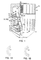
- Figure 1 is a longitudinal view, partly in section, of the chuck in accordance with an embodiment of the present invention;
- Figure 1A is a sectional view of the
embodiment of Figure 1 taken along
lines 1A-1A; - Figure 1B is a sectional view of an alternate
embodiment of the drive arrangement taken along
lines 1B-1B of Figure 1; - Figure 2 is an exploded view of a chuck in accordance with the embodiment in Figure 1;
- Figure 3 is a longitudinal cross sectional view of a chuck in accordance with another embodiment of the present invention;
- Figure 4 is a longitudinal cross sectional view of a chuck in accordance with still another embodiment of the present invention;
- Figure 5 is a longitudinal cross sectional view of another embodiment of the present invention;
- Figure 6 is a frontal view of a chuck in accordance with an embodiment of the present invention.
-
- Repeat use of reference characters in the present specification and drawings is intended to represent same or analogous features or elements of the invention.
- It is to be understood by one of ordinary skill in the art that the present discussion is a description of exemplary embodiments only, and is not intended as limiting the broader aspects of the present invention, which broader aspects are embodied in the exemplary construction.
- Referring to Figures 1 and 2, a
chuck 10 in accordance with the present invention is illustrated. Chuck 10 includes afront sleeve member 12, an optionalrear sleeve member 14, abody member 16 andjaws 18.Body member 16 is generally cylindrical in shape and comprises a nose orforward section 20 and a tail orrearward section 22. Anaxial bore 24 is formed in thenose section 20 of thebody member 16.Axial bore 24 is dimensioned somewhat larger than the largest tool shank that the chuck is designed to accommodate. A threadedbore 26 is formed intail section 22 ofbody 16 and is of a standard size to mate with the drive shaft of a powered or hand driver (not shown). Thebores central region 28 ofbody member 16. While a threadedbore 26 is illustrated, such bore could be replaced with a tapered bore of a standard size to mate with a tapered drive shaft. - Passageways 30 are formed in
body member 16 to accommodate eachjaw 18. Threejaws 18 are employed and eachjaw 18 is separated from the adjacent jaw by an arc of approximately 120 degrees. The axes of thepassageways 30 and thejaws 18 are angled with respect to the chuck axis and intersect the chuck axis at a common point ahead of thechuck body 16. Eachjaw 18 has atool engaging face 32 which is generally parallel to the axis of thechuck body 16 andthreads 34 on its opposite or outer surface.Threads 34 of any suitable type and pitch may be utilized within the scope of the present invention as would be readily apparent to one skilled in the art. - As illustrated in Figures 1 and 2,
body member 16 includes athrust ring member 36 which, in a preferred embodiment, may be integral therewith. In an alternate embodiment,thrust ring member 36 may be a separate component from the body member.Thrust ring member 36 may also include aledge portion 38.Ledge portion 38 is adapted for engagement with a portion of a bearing assembly such as illustrated at 62 and as will be described in more detail below.Thrust ring member 36 includes a plurality ofjaw guideways 42 formed around the circumference to permit retraction of thejaws 18 therethrough. -
Body member 16 includes a rearcylindrical portion 22 with aknurled surface 46 thereon for receipt of optionalrear sleeve 14 to be pressed thereon if so desired. It should be appreciated thatrear sleeve 14 could also be retained in place by press fit without knurling or by use of a key. It could also be retained in place by crimping, staking, riveting, threading or any other suitable securing mechanism. -
Body 16 further includes agroove 44 in the forward section.Groove 44 is adapted to receive asnap ring 46 or the like for retaining a nut in place as will be described in more detail below. - The present invention further includes a
nut 48 which, in a preferred embodiment, is a one piece nut and which includesthreads 50 for mating withthreads 34 onjaws 18 whereby whennut 48 is rotated with respect tobody 16, the jaws will be advanced or retracted.Nut 48 may include driveslots 52 for mating withdrive ribs 54 onfront sleeve 12 so that whenfront sleeve 12 is rotated,nut 48 will rotate therewith and movejaws 18 as set forth above. -
Nut 48 includes afirst portion 56 and asecond portion 58 extending axially outwardly from the first portion, the second portion having an outside diameter less than the outside diameter of the first portion.Nut 48 also may include a ledge portion 60 (Figure 1) that is configured to mate with a portion of a bearing such as 62. It should be appreciated that although anantifriction bearing 62 is illustrated,a plain or coated bearing surface or friction reducing washer could be utilized in place of bearing 62. In addition, a self-contained baring assembly could also be utilized. - In a preferred embodiment as set forth above,
front sleeve member 12 is adapted to be loosely fitted overnose section 20 ofchuck 10.Multiple drive ribs 54 offront sleeve 12 engagedrive slots 52 ofnut 48 so thatfront sleeve 12 andnut 48 will be operatively connected, i.e., whenfront sleeve 12 is rotated,nut 48 will rotate therewith. Referring to Figures 1A and 1B,drive ribs 54 may extend in an arcuate manner as shown in Figure 1A at 64 or in a substantially rectangular manner from said sleeve as illustrated in Figure 1B at 66. Thedrive slots 52 on thenut 48 may be configured to generally conform to the configuration of the drive ribs on the sleeve. -
Body member 16 may include anadditional groove 68 on itsforward section 20. A sleeve retainingsnap ring 70 may be received ingroove 68 for retainingfront sleeve 12 in place. Referring to Figures 1 and 2, sleeve retainingsnap ring 70 consists of a circular ring that is disconnected or broken along its circumference at 72. This disconnection allowssnap ring 70 to fit intogroove 68 onbody member 16.Snap ring 70 includes a substantially circular firstaxial portion 74 adapted to be received in agroove 68 onbody member 16.Snap ring 70 also includes a second substantiallycircular portion 76 extending from said first portion in an L-shaped manner (Figure 1). Second substantiallycircular portion 76 includes a first portion 77 extending radially outwardly from firstaxial portion 74 and asecond portion 79 extending axially outward from portion 77 in a cantilevered manner.Second portion 76 is flexible so that when saidfirst portion 74 is received ingroove 68 onbody 16 andsleeve 12 is pressed oversnap ring 70, a contact portion 78 ofsleeve 12 will deflectsecond portion 76 to allowsecond portion 76 to be received in agroove 80 onsleeve 12. In this manner,sleeve 12 can be secured in place bysnap ring 70. As can be appreciated,snap ring 70 is a one-way snap ring so thatsleeve 12 is prevented from separating from the chuck. As illustrated in Figure 1, a portion ofsleeve 12 may bear against the outer surface of a section ofportion 74 to provide additional rotational stability to thesleeve 12. It would be preferable in this instance for at least this portion ofsnap ring 70 to be constructed of a friction reducing material. - In a preferred embodiment,
snap ring 70 is constructed of a polymeric material such as nylon and includesrelief areas 82 to enhance the flexibility ofportion 74. Of course,snap ring 70 could be constructed of any suitable single or composite material. As set forth above,rear sleeve member 14 is optional. If desired,rear sleeve member 14 may be omitted and thefront sleeve member 12 extended to the tail end ofbody 16. This alternative is feasible when a spindle lock or the like is provided on the driver or when the driver is used to tighten or loosen the jaws. - The circumferential surface of the
front sleeve member 12 may be knurled or may be provided with longitudinal ribs or other protrusions to enable the operator to grip it securely. In like manner, the circumferential surface of therear sleeve member 14, if employed, may be knurled or ribbed if desired. The front and rear sleeves may be fabricated from a structural plastic such as polycarbonate, a filled polypropylene, for example, glass filled polypropylene, or a blend of structural plastic materials. Other composite materials such as, for example, graphite filled polymerics would also be suitable in certain environments. As will be appreciated by one skilled in the art, the materials from which the chuck of the present invention is fabricated will depend on the end use of the chuck, and the above are provided by way of example only. - It will be appreciated that
rear sleeve member 14 is fixed tobody member 16 whilefront sleeve member 12 is operatively associated withnut 48 and secured tobody member 16 for relative rotation therewith. Relative movement of the front and rear sleeve members, 12 and 14, due to the interaction betweenthreads 34 onjaws 18 andthreads 50 onnut 48causes jaws 18 to be advanced or retracted, depending upon the direction of relative movement. - Referring to Figure 3, another embodiment of a chuck in accordance with the present invention is illustrated at 110. This embodiment also includes a
front sleeve 112 and an optionalrear sleeve 114 both received onbody member 116. The operation of the chuck as illustrated in the embodiment of Figure 3 is the same as the embodiment of Figures 1 and 2 with respect to the interaction of thenut 148 withjaws 118, as well as retention ofnut 148 in place bysnap ring 146. The primary difference between the embodiment of Figure 1 and 2 and the embodiment of Figure 3 is thatsleeve 112 is press fitted ontonut 148 to maintainsleeve 112 in place. This press fit arrangement also provides the drive engagement betweenfront sleeve 112 andnut 148.Nut 148 may include aknurled portion 185 for engagement withouter sleeve 112 to prevent slippage upon rotation betweensleeve 112 andnut 148. Of course, in the embodiment illustrated in Figure 3, a sleeve retaining snap ring, such as 70 illustrated in Figure 1, would not be necessary, but it should be appreciated that such could be utilized if desired. - Referring to Figure 4, another embodiment of the chuck in accordance with the present invention is illustrated generally at 210.
Chuck 210 includesbody member 216, afront sleeve member 212 and arear sleeve member 214.Body member 216 is generally cylindrical in shape and comprises a nose orforward section 220 and a tail orrear section 222. Anaxial bore 224 is formed in thenose section 220 of thebody member 216.Bore 224 is configured in the same manner as bore 24 in the embodiment illustrated in Figures 1 and 2. The threaded bore 226 is formed intail section 222 ofbody 216 in the same manner as illustrated with respect to Figures 1 and 2. -
Passageways 230 are formed inbody member 216 to accommodate eachjaw 218, again in the same manner as set forth with respect to the embodiment of Figures 1 and 2. - In the embodiment illustrated in Figure 4, nut 248 (preferably unitary) may be received in a
nut receiving portion 249 insleeve 212. Nut receiving portion includes aledge 250 to prevent movement of the nut in the forward direction, and asnap ring 251 is provided in agroove 252 insleeve 212 to prevent rearward movement ofnut 248. Any type interengaging mechanism betweensleeve 212 andnut 248 to provide for rotational movement ofnut 248 whensleeve 212 is rotated could be utilized including, for example, drive ribs and drive grooves as described with respect to the embodiment of Figures 1 and 2, or press fit as described with respect to the embodiment of Figure 3. -
Sleeve 212 further includes arear ledge portion 254 adapted to engage a bearingmember 256 which is received betweenledge portion 254 and aledge 258 onrear sleeve member 214. It should be appreciated that bearingmember 256 can be any type known bearing member including, if desired, a coated or uncoated bearing surface, or a self-contained bearing assembly. On the forward portion ofsleeve 212 is anotherbearing receiving ledge 260 which receives a bearing member 262 which is retained therein by a retainingmember 264. Again, it should be appreciated that bearing member 262 could be a coated or uncoated bearing surface or any suitable bearing member in accordance with the above discussions.Front sleeve 212 further includes a retainingledge 266. The forward section ofbody member 216 includes agroove 268 therein for receipt of a retaining member such as a snap ring 270 or the like. - In operation,
nut 248 is received insleeve 212 and maintained in place by retainingmember 251.Sleeve 212 is placed over the forward section ofbody member 216 and the rear portion ofsleeve 212 engages a bearing member or bearingsurface 256 which engages a portion ofsleeve 214 thereon. In the forward section ofsleeve 212 there is another bearing member or surface 262, and where such is a bearing member, it is retained in place by a retainingmember 264. The entire sleeve is maintained in place in the forward direction by retaining member 270 which is received ingroove 268 on the forward section of the body and in the rearward direction byledge 258. It should be appreciated that bearing 262 may be press fitted onto the body and retaining member 270 may be optional. - Figure 5 illustrates at 310 another embodiment of a chuck in accordance with the present invention.
Chuck 310 includes afront sleeve member 312, an optionalrear sleeve member 314, abody member 316 andjaws 318.Body member 316 is generally cylindrical in shape and comprises a nose orforward section 320 and a tail or rearward section 322. Anaxial bore 324 is formed in thenose section 320 of thebody member 316, and a threadedbore 326 is formed in the tail section ofbody member 316 and is of a standard size to mate with the drive shaft of a power or hand driver (not shown). As discussed above with respect to the embodiments of Figures 1-4, thebores central region 328 of thebody member 316. -
Passageways 330 are formed inbody member 316 to accommodate eachjaw 318 as set forth with respect to the above embodiments.Body member 316 also includes athrust ring portion 336. A bearingmember 338 is received betweenthrust ring member 336 and anut 340. While the bearingmember 338 is illustrated, it should be appreciated that a coated or uncoated bearing surface could be utilized in place of the bearing member or a self-contained bearing assembly could be utilized. In a preferred embodiment,nut 340 is a one-piece nut and is prevented from forward movement byledge 342 ofsleeve 312. A bearingwasher 344 is received about thenose section 320 ofbody member 316 and includes aledge portion 346 which engages a forward portion offront sleeve 312.Member 344 may be plastic, nylon, teflon or any other suitable material and can, in general, be considered as a bearing washer to minimize friction whensleeve 312 is rotated. - A
nosepiece 348 is received on theforward section 320 ofbody member 316 by means of a press fit or the like. The rearward portion ofnosepiece 348 contacts the forward portion ofmember 344 so thatsleeve 312 is maintained in place throughmember 344 bynosepiece 348 that is pressed onto the forward section ofbody member 316. It should be appreciated that while a one-piece nosepiece is illustrated at 348, such could be a multiple piece nosepiece or any other suitable retaining member. - In the embodiment illustrated in Figure 5,
nut 340 is maintained in place bynosepiece 348 throughmember 344 andsleeve 312. The operation of the chuck as illustrated in the embodiment of Figure 5 is essentially as set forth with respect to the embodiment of Figures 1 and 2.Sleeve member 312 may have drive ribs andnut 340 may have drive rib receiving grooves so that whensleeve 312 is rotated,nut 340 will rotate therewith. In addition,sleeve 312 could be press fitted ontonut 340 or attached in any other suitable manner. - Figure 6 illustrates an alternate embodiment of the present invention. As illustrated in Figure 6 at 400, the interior diameter of
bore 405 in the forward section of the body may include a configuration such that a suitable tool may be utilized to rotate the body when the jaws are retracted into the chuck. Such a configuration may be such as a multi-sided star shape as illustrated in Figure 6, or a polygonal shape or any other suitable shape with which a tool could be inserted so as to rotate the body member to screw the chuck body onto a driver spindle. In addition, the wrench configuration could be adapted into the outside diameter of the forward portion of the body member so that a suitable socket or other mechanism could be received over the nose section of the body member to rotate the chuck body to thereby tighten it onto a spindle or the like. - While the above description is set forth with respect to a keyless chuck, it should be appreciated that many of the principles of the present invention are equally applicable to a keyed chuck, and such is within the scope of the present invention.
- These and other modifications and variations to the present invention may be practiced by those of ordinary skill in the art, without departing from the spirit and scope of the present invention, which is more particularly set forth in the appended claims. In addition, it should be understood that aspects of the various embodiments may be interchanged both in whole or in part. Furthermore, those of ordinary skill in the art will appreciate that the foregoing description is by way of example only, and is not intended to be limitative of the invention so further described in such appended claims.
Claims (14)
- A chuck (10,110,210,310) for use with a manual or powered driver having a rotatable drive shaft, said chuck comprising:a generally cylindrical body member (16,116,216,316), said body member (16,116,216,316) having a forward section (20,120,130) and a rearward section (22,222,322), said rearward section (22,222,322) having an axial bore (26,226,325) formed therein to mate with said drive shaft of said driver and said forward section (20,220,320) having an axial bore (24,224,324) formed therein and a plurality of angularly disposed passageways (30,230,330) formed therethrough and intersecting said axial bore (24,224,324):a plurality of jaws (18,118,218,318) slidably positioned in each of said angularly disposed passageways (30,230,330), each of said jaws (18,118,218,318) having a jaw face (32) formed on one side thereof and threads (34) formed on the opposite side thereof;a unitary nut (48,148,248,340) rotatably mounted relative to said body (16,116,216,316) so as to engage said jaw threads (34); anda generally cylindrical sleeve member (12,112,212,312) received over the forward section of said body member (16,116,216,316) for engaging said nut (48, 148,248,348) so that when said sleeve member (12,112,212,312) is rotated, said nut (48.148.248.340) will be rotated therewith to operate said jaws (18,118,218,318), characterised in that said sleeve member (212) further includes a bearing member (262) retained in the forward section of said sleeve member (212) and adapted to engage the forward section (220) of said body member (216), said bearing member (262) serving as a thrust bearing.
- A chuck for use with a manual or powered driver as in claim 1, wherein said bearing member (262) is pressed onto the forward portion (220) of said body. member (216) to retain said front sleeve (212) on the body member (216) during operation of the chuck.
- A chuck for use with a manual or powered driver as in claim 1, wherein said front sleeve (212) is retained on said body member (216) by a locking ring (270) received in a groove (268) on the forward section of the body member (216) and engaging a portion of the front sleeve (212).
- A chuck for use with a manual or powered driver as in claim 1, wherein said bearing member (262) is retained in said sleeve by a locking ring (264).
- A chuck for use with a manual or powered driver as in claim 1, wherein said unitary nut (248) is retained in said sleeve (212) by a locking ring (251) received in a groove (252) in said sleeve (212) and abutting a portion of said nut (248).
- A chuck for use with a manual or powered driver as in claim 1, and further including a rear sleeve (214) fixed to the rearward section (222) of the body member (216).
- A chuck for use with a manual or powered driver as in claim 6, and further including a bearing member (256) received between a rearward portion of said front sleev (212) and a forward portion of said rear sleeve (214).
- A chuck (10,110,210,310) for use with a manual or powered driver having a rotatable drive shaft, said chuck comprising:a generally cylindrical body member (16,116,216,316), said body member (16,116,216,316) having a forward section (20,120,130) and a rearward section (22,222,322), said rearward section (22,222,322) having an axial bore (26,226,325) formed therein to mate with said drive shaft of said driver and said forward section (20,220,320) having an axial bore (24,224,324) formed therein and a plurality of angularly disposed passageways (30,230,330) formed therethrough and intersecting said axial bore (24,224,324);a plurality of jaws (18,118,218,318) slidably positioned in each of said angularly disposed passageways (30,230,330), each of said jaws (18,118,218,318) having a jaw face (32) formed on one side thereof and threads (34) formed on the opposite side thereof;a unitary nut (48,148,248,340) rotatably mounted relative to said body (16,116,216,316) so as to engage said jaw threads (34); anda generally cylindrical sleeve member (12,112,212,312) received over the forward section of said body member (16,116,216,316) for engaging said nut (48,148,248,348) so that when said sleeve member (12,112,212,312) is rotated, said nut (48,148,248,340) will be rotated therewith to operate said jaws (18,118,218,318), characterised in that a bearing member (262) is received about the forward section (224) of said body member (216) and supports said sleeve member (212) rotatably thereon; anda retaining member (270) is secured on the forward section of the body member (216) for retaining said sleeve (212) in place through said bearing member (262).
- A chuck for use with a manual or powered driver as in claim 8, wherein said sleeve is polymeric and said nut is co-moulded into said sleeve.
- A chuck for use with a manual or powered driver as in claim 8 or 9, and further including a rear sleeve (314) fixed to the rearward section of said body member (316).
- A chuck for use with a manual or powered driver as in claim 8 to 10, and further including a thrust flange (336) fixed on said body member (316) and a bearing member (338) located between a face of said nut (340) and said thrust flange (336).
- A chuck for use with a manual or powered driver as in claims 8 to 11. wherein said retaining member is a decorative nosepiece (348) pressed onto the forward section of said body member (316).
- A chuck for use with a manual or powered driver as in claims 8 to 12, wherein the bearing member is a bearing washer (344).
- A chuck for use with a manual or powered driver as claimed in any preceding claim, said forward section being configured to receive a tool for tightening said body to said drive shaft.
Applications Claiming Priority (3)
| Application Number | Priority Date | Filing Date | Title |
|---|---|---|---|
| US269553 | 1994-07-01 | ||
| US08/269,553 US5553873A (en) | 1994-07-01 | 1994-07-01 | Keyless chuck |
| EP95918315A EP0768930B1 (en) | 1994-07-01 | 1995-04-26 | Chuck |
Related Parent Applications (1)
| Application Number | Title | Priority Date | Filing Date |
|---|---|---|---|
| EP95918315A Division EP0768930B1 (en) | 1994-07-01 | 1995-04-26 | Chuck |
Publications (3)
| Publication Number | Publication Date |
|---|---|
| EP1013366A2 true EP1013366A2 (en) | 2000-06-28 |
| EP1013366A3 EP1013366A3 (en) | 2000-07-05 |
| EP1013366B1 EP1013366B1 (en) | 2004-11-03 |
Family
ID=23027741
Family Applications (2)
| Application Number | Title | Priority Date | Filing Date |
|---|---|---|---|
| EP00200430A Expired - Lifetime EP1013366B1 (en) | 1994-07-01 | 1995-04-26 | Keyless chuck |
| EP95918315A Expired - Lifetime EP0768930B1 (en) | 1994-07-01 | 1995-04-26 | Chuck |
Family Applications After (1)
| Application Number | Title | Priority Date | Filing Date |
|---|---|---|---|
| EP95918315A Expired - Lifetime EP0768930B1 (en) | 1994-07-01 | 1995-04-26 | Chuck |
Country Status (11)
| Country | Link |
|---|---|
| US (1) | US5553873A (en) |
| EP (2) | EP1013366B1 (en) |
| JP (1) | JPH10504764A (en) |
| CN (1) | CN1061916C (en) |
| AU (1) | AU2428895A (en) |
| BR (1) | BR9508215A (en) |
| CA (1) | CA2193694A1 (en) |
| DE (2) | DE69533732T2 (en) |
| MX (1) | MX9700160A (en) |
| RU (1) | RU2124420C1 (en) |
| WO (1) | WO1996001165A1 (en) |
Families Citing this family (33)
| Publication number | Priority date | Publication date | Assignee | Title |
|---|---|---|---|---|
| USD386193S (en) * | 1996-08-09 | 1997-11-11 | Power Tool Holders Incorporated | Chuck |
| US5741016A (en) † | 1996-10-02 | 1998-04-21 | Power Tool Holders Incorporated | Chuck |
| US5816583A (en) * | 1996-12-04 | 1998-10-06 | Power Tool Holders, Inc. | Integral locking sleeve chuck |
| US5816584A (en) * | 1997-01-02 | 1998-10-06 | Power Tool Holders, Inc. | Chuck with improved jaw bite |
| US6010135A (en) * | 1997-05-29 | 2000-01-04 | Power Tool Holders, Inc. | Chuck |
| USD421615S (en) * | 1997-08-04 | 2000-03-14 | Black & Decker Inc. | Keyless chuck |
| US6045141A (en) * | 1997-08-06 | 2000-04-04 | Power Tool Holders, Inc. | Molded chuck |
| US6017039A (en) * | 1997-11-03 | 2000-01-25 | Power Tool Holders Incorporated | Nosepiece nut retainer chuck |
| US5934689A (en) * | 1998-02-17 | 1999-08-10 | Power Tool Holders, Inc. | Chuck having sleeve retaining nut |
| US5944328A (en) * | 1998-02-20 | 1999-08-31 | Chum Power Machinery Corp. | Chuck |
| US6102411A (en) * | 1998-08-14 | 2000-08-15 | Power Tool Holders, Inc. | Chuck with locking sleeve |
| US5934690A (en) * | 1998-09-02 | 1999-08-10 | Chum Power Machinery Corp. | Chuck unit of a power hand tool |
| US6354605B1 (en) | 2000-03-10 | 2002-03-12 | Power Tool Holders Incorporated | Chuck with improved jaw |
| US6540237B1 (en) | 2000-06-23 | 2003-04-01 | Power Tool Holders Incorporated | Chuck |
| AUPR272101A0 (en) * | 2001-01-24 | 2001-02-22 | Bayly Design Associates Pty Ltd | Power tool |
| US7451990B2 (en) * | 2004-04-29 | 2008-11-18 | Jacobs Chuck Manufacturing Company | Chuck with torque indicator |
| US20070063455A1 (en) * | 2004-09-17 | 2007-03-22 | Zhang Qiang J | Fastener with nutating gear reduction |
| US7331584B2 (en) * | 2004-09-17 | 2008-02-19 | Black & Decker Inc. | Chuck with nutating gear reduction |
| US7690658B2 (en) | 2004-09-20 | 2010-04-06 | Black & Decker Inc. | Tool chuck with power take off feature |
| US7243923B2 (en) | 2005-02-09 | 2007-07-17 | Black & Decker Inc. | Centering drill chuck |
| US7588398B2 (en) * | 2005-04-19 | 2009-09-15 | Black & Decker Inc. | Tool chuck with power take off and dead spindle features |
| US7645101B2 (en) * | 2005-09-16 | 2010-01-12 | Black & Decker Inc. | Chuck with internally threaded jaw in a PTO application |
| US7547165B2 (en) * | 2005-09-16 | 2009-06-16 | Black & Decker Inc. | PTO selector mechanism with brake |
| US7588399B2 (en) * | 2005-09-16 | 2009-09-15 | Black & Decker Inc. | PTO selector mechanism for parallel axis transmission |
| US7537421B2 (en) | 2005-09-16 | 2009-05-26 | Black & Decker Inc. | Dead spindle PTO with compliant grounding mechanism |
| US7637510B2 (en) * | 2005-10-12 | 2009-12-29 | Shandong Weida Machinery Company Limited | Chuck with gripping mechanism stop |
| DE102006011344A1 (en) * | 2006-03-11 | 2007-09-13 | Röhm Gmbh | Drill chuck, has rotating bush supported at axially rear end of chuck body and coupled with part of web retainer or locking device in torque transferable manner, where web retainer is utilized for actuating clamping jaw |
| US8075229B2 (en) * | 2007-06-26 | 2011-12-13 | Techtronic Power Tools Technology Limited | Multi-speed drill and chuck assembly |
| US8057134B2 (en) | 2007-06-26 | 2011-11-15 | Techtronic Power Tools Technology Limited | Chuck assembly |
| US20090200758A1 (en) * | 2008-02-07 | 2009-08-13 | Chin Hung Lam | Auto Locking Chuck |
| DE102010061466A1 (en) | 2010-12-22 | 2012-06-28 | Röhm Gmbh | chuck |
| DE102015102241A1 (en) * | 2015-02-17 | 2016-08-18 | Röhm Gmbh | chuck |
| RU191476U1 (en) * | 2019-04-29 | 2019-08-07 | Владимир Васильевич Галайко | Twist drill |
Citations (11)
| Publication number | Priority date | Publication date | Assignee | Title |
|---|---|---|---|---|
| US2292470A (en) * | 1939-03-16 | 1942-08-11 | Ostberg Karl Gustaf | Rotary clutching device |
| US3807745A (en) * | 1973-03-15 | 1974-04-30 | J Bent | Keyless drill chuck |
| US3934891A (en) * | 1973-04-11 | 1976-01-27 | The Jacobs Manufacturing Co., Ltd. | Drill chuck and method of assembly |
| US4097054A (en) * | 1975-10-07 | 1978-06-27 | The Jacobs Manufacturing Company, Limited | Drill chucks |
| FR2606691A1 (en) * | 1986-11-19 | 1988-05-20 | Black & Decker Inc | Quick-acting three-jaw chuck |
| EP0300375A1 (en) * | 1987-07-21 | 1989-01-25 | Yukiwa Seiko Inc. | Chuck for tools |
| EP0340310A1 (en) * | 1987-10-16 | 1989-11-08 | Sakamaki Mfg. Co., Ltd. | Chuck for tools |
| US5145192A (en) * | 1990-07-21 | 1992-09-08 | Roehm Guenter H | Lockable drill chuck |
| US5158306A (en) * | 1990-07-21 | 1992-10-27 | Roehm Guenter H | Drill chuck |
| US5193824A (en) * | 1992-08-07 | 1993-03-16 | Jacobs Chuck Technology Corp. | Chuck having a drive bit socket |
| EP0542165A1 (en) * | 1991-11-11 | 1993-05-19 | Jacobs Japan, Inc. | A tool chuck |
Family Cites Families (49)
| Publication number | Priority date | Publication date | Assignee | Title |
|---|---|---|---|---|
| US913059A (en) * | 1907-04-17 | 1909-02-23 | Edward S Savage | Chuck. |
| US911012A (en) * | 1908-03-16 | 1909-01-26 | Jacobs Mfg Co | Chuck. |
| US1123541A (en) * | 1912-09-19 | 1915-01-05 | Jacobs Mfg Co | Chuck. |
| US1417981A (en) * | 1921-05-27 | 1922-05-30 | Jacobs Mfg Co | Chuck |
| US1476903A (en) * | 1923-02-07 | 1923-12-11 | Mcconnell Browning Engineering | Chuck |
| US1784002A (en) * | 1926-09-08 | 1930-12-09 | Jacobs Mfg Co | Chuck |
| US1773034A (en) * | 1928-01-23 | 1930-08-12 | Jacobs Mfg Co | Chuck |
| US1970056A (en) * | 1931-06-17 | 1934-08-14 | Edward J O'flaherty | Tool chuck |
| US2684856A (en) * | 1950-03-18 | 1954-07-27 | Jacobs Mfg Co | Apparatus for tightening chucks of power drills |
| GB1330065A (en) * | 1971-07-21 | 1973-09-12 | Jacobs Mfg Co | Drill chucks |
| IT1077357B (en) * | 1977-03-14 | 1985-05-04 | Star Utensili Elett | SELF-CENTERING SPINDLE, IN PARTICULAR FOR PORTABLE ELECTRIC TOOLS |
| US4252333A (en) * | 1978-09-11 | 1981-02-24 | Black & Decker Inc. | Keyless chuck |
| US4381116A (en) * | 1979-05-07 | 1983-04-26 | Futter Friedrich P | Futter chuck |
| US4275893A (en) * | 1979-08-31 | 1981-06-30 | Black & Decker Inc. | Self-tightening keyless chuck |
| US4305597A (en) * | 1979-11-19 | 1981-12-15 | Black & Decker Inc. | Keyless self-tightening chuck |
| FR2485966A1 (en) * | 1980-07-04 | 1982-01-08 | Amyot Ets Sa | MANDREL FOR FIXING A TOOL ON A MACHINE TOOL |
| US4423881A (en) * | 1982-06-21 | 1984-01-03 | Whitehead Dennis M | Quick operating chuck |
| DE3411127A1 (en) * | 1984-03-26 | 1985-10-03 | Helmut Dipl.-Ing. Höger (FH), 7312 Kirchheim | Drill chuck |
| US4682918A (en) * | 1984-04-16 | 1987-07-28 | Milwaukee Electric Tool Corporation | Keyless impacting chuck |
| DE3439668A1 (en) * | 1984-09-17 | 1986-04-30 | Hilti Ag, Schaan | Keyless quick-action chuck |
| US4660841A (en) * | 1985-01-14 | 1987-04-28 | Chouinard Michael J | Hand tightenable device for holding a cutting implement |
| US4648608A (en) * | 1985-02-27 | 1987-03-10 | Black & Decker, Inc. | Low-cost, keyless chuck and method of manufacture |
| JPS62166906A (en) * | 1986-01-21 | 1987-07-23 | Matsushita Electric Works Ltd | Chucking tool |
| JPS63216604A (en) * | 1987-03-05 | 1988-09-08 | Sakamaki Seisakusho:Kk | Tool chuck |
| US4848779A (en) * | 1987-04-02 | 1989-07-18 | Black & Decker Inc. | Keyless chuck |
| JPH0192009A (en) * | 1987-06-12 | 1989-04-11 | Sakamaki Seisakusho:Kk | Chuck for tool |
| JPS649005U (en) * | 1987-07-03 | 1989-01-18 | ||
| US4817971A (en) * | 1987-07-16 | 1989-04-04 | Flynn Jerome R | Chuck actuator device and method |
| JPS6427804A (en) * | 1987-07-21 | 1989-01-30 | Sakamaki Seisakusho Kk | Chuck for tool |
| US5234223A (en) * | 1987-07-21 | 1993-08-10 | Sakamaki Mfg. Co., Ltd. | Chuck for tools |
| DE3727147A1 (en) * | 1987-08-14 | 1989-02-23 | Roehm Guenter H | TENSIONING DRILL CHUCK |
| US4840387A (en) * | 1988-01-20 | 1989-06-20 | The Jacobs Manufacturing Company | Self-actuating keyless chuck |
| DE3808155A1 (en) * | 1988-03-11 | 1989-09-21 | Roehm Guenter H | DRILL CHUCK SET UP FOR CONNECTION TO A DRILL SPINDLE |
| JPH0283105A (en) * | 1988-03-28 | 1990-03-23 | Matsushita Electric Works Ltd | Fastening tool |
| US5044643A (en) * | 1989-06-16 | 1991-09-03 | Daijiro Nakamura | Tool chuck |
| US5125673A (en) * | 1989-12-11 | 1992-06-30 | Huff Robert O | Non-impact keyless chuck |
| US5452906B1 (en) * | 1989-12-11 | 1997-07-29 | Power Tool Holders Inc | Non-impact keyless chuck |
| US5253879A (en) * | 1989-12-11 | 1993-10-19 | Jacobs Chuck Technology Corporation | Non-impact keyless chuck |
| FR2655581B1 (en) * | 1989-12-11 | 1993-12-31 | Amyot Sa Ets | TOOL HOLDER CHUCK FOR THE EQUIPMENT OF A ROTATING MACHINE SUCH AS A DRILL. |
| DE4005757A1 (en) * | 1990-02-23 | 1991-08-29 | Bosch Gmbh Robert | Hand-tool machine with drill chuck - incorporates locking device preventing loosening of chuck jaws during operation |
| DE4023303C1 (en) * | 1990-07-21 | 1991-09-26 | Guenter Horst 7927 Sontheim De Roehm | |
| JPH0783961B2 (en) * | 1991-06-13 | 1995-09-13 | ユキワ精工株式会社 | Tool chuck |
| JPH0538608A (en) * | 1991-07-31 | 1993-02-19 | Hitachi Koki Co Ltd | Chuck |
| US5215317A (en) * | 1992-05-18 | 1993-06-01 | Jacobs Chuck Technology Corp. | Keyless chuck |
| FR2702975B1 (en) * | 1993-03-26 | 1995-06-16 | Amyot Ets Sa | TOOL HOLDER CHUCK FOR THE EQUIPMENT OF A ROTATING MACHINE, SUCH AS A DRILL. |
| US5390940A (en) * | 1993-05-26 | 1995-02-21 | Jacobs Chuck Technology Corporation | Keyless chuck with integral threaded ring |
| US5348318A (en) * | 1993-08-13 | 1994-09-20 | Jacobs Chuck Technology Corporation | Chuck |
| US5348317A (en) * | 1993-08-13 | 1994-09-20 | Jacobs Chuck Technology Corporation | Chuck |
| DE9320006U1 (en) * | 1993-12-24 | 1994-02-10 | Roehm Guenter H | Drill chuck with dust cap |
-
1994
- 1994-07-01 US US08/269,553 patent/US5553873A/en not_active Expired - Lifetime
-
1995
- 1995-04-26 AU AU24288/95A patent/AU2428895A/en not_active Abandoned
- 1995-04-26 DE DE69533732T patent/DE69533732T2/en not_active Expired - Fee Related
- 1995-04-26 EP EP00200430A patent/EP1013366B1/en not_active Expired - Lifetime
- 1995-04-26 BR BR9508215A patent/BR9508215A/en not_active Application Discontinuation
- 1995-04-26 EP EP95918315A patent/EP0768930B1/en not_active Expired - Lifetime
- 1995-04-26 JP JP8503860A patent/JPH10504764A/en active Pending
- 1995-04-26 MX MX9700160A patent/MX9700160A/en unknown
- 1995-04-26 RU RU97101477A patent/RU2124420C1/en active
- 1995-04-26 DE DE69528980T patent/DE69528980T2/en not_active Expired - Lifetime
- 1995-04-26 WO PCT/US1995/005246 patent/WO1996001165A1/en active IP Right Grant
- 1995-04-26 CN CN95194804A patent/CN1061916C/en not_active Expired - Fee Related
- 1995-04-26 CA CA002193694A patent/CA2193694A1/en not_active Abandoned
Patent Citations (11)
| Publication number | Priority date | Publication date | Assignee | Title |
|---|---|---|---|---|
| US2292470A (en) * | 1939-03-16 | 1942-08-11 | Ostberg Karl Gustaf | Rotary clutching device |
| US3807745A (en) * | 1973-03-15 | 1974-04-30 | J Bent | Keyless drill chuck |
| US3934891A (en) * | 1973-04-11 | 1976-01-27 | The Jacobs Manufacturing Co., Ltd. | Drill chuck and method of assembly |
| US4097054A (en) * | 1975-10-07 | 1978-06-27 | The Jacobs Manufacturing Company, Limited | Drill chucks |
| FR2606691A1 (en) * | 1986-11-19 | 1988-05-20 | Black & Decker Inc | Quick-acting three-jaw chuck |
| EP0300375A1 (en) * | 1987-07-21 | 1989-01-25 | Yukiwa Seiko Inc. | Chuck for tools |
| EP0340310A1 (en) * | 1987-10-16 | 1989-11-08 | Sakamaki Mfg. Co., Ltd. | Chuck for tools |
| US5145192A (en) * | 1990-07-21 | 1992-09-08 | Roehm Guenter H | Lockable drill chuck |
| US5158306A (en) * | 1990-07-21 | 1992-10-27 | Roehm Guenter H | Drill chuck |
| EP0542165A1 (en) * | 1991-11-11 | 1993-05-19 | Jacobs Japan, Inc. | A tool chuck |
| US5193824A (en) * | 1992-08-07 | 1993-03-16 | Jacobs Chuck Technology Corp. | Chuck having a drive bit socket |
Also Published As
| Publication number | Publication date |
|---|---|
| MX9700160A (en) | 1997-04-30 |
| EP0768930A1 (en) | 1997-04-23 |
| DE69533732D1 (en) | 2004-12-09 |
| EP1013366B1 (en) | 2004-11-03 |
| DE69533732T2 (en) | 2005-10-27 |
| JPH10504764A (en) | 1998-05-12 |
| CN1061916C (en) | 2001-02-14 |
| RU2124420C1 (en) | 1999-01-10 |
| DE69528980D1 (en) | 2003-01-09 |
| CN1156423A (en) | 1997-08-06 |
| CA2193694A1 (en) | 1996-01-18 |
| EP1013366A3 (en) | 2000-07-05 |
| AU2428895A (en) | 1996-01-25 |
| BR9508215A (en) | 1998-07-14 |
| EP0768930B1 (en) | 2002-11-27 |
| US5553873A (en) | 1996-09-10 |
| WO1996001165A1 (en) | 1996-01-18 |
| DE69528980T2 (en) | 2003-07-17 |
Similar Documents
| Publication | Publication Date | Title |
|---|---|---|
| EP1013366B1 (en) | Keyless chuck | |
| US5348318A (en) | Chuck | |
| US5816583A (en) | Integral locking sleeve chuck | |
| EP1270119B1 (en) | Chuck | |
| EP0775033B1 (en) | Chuck | |
| US5816582A (en) | Chuck | |
| US5957469A (en) | Spring chuck | |
| US6311988B1 (en) | Chuck with locking sleeve | |
| US6017039A (en) | Nosepiece nut retainer chuck | |
| US6540237B1 (en) | Chuck | |
| WO1998047650A1 (en) | Chuck with locking nut | |
| GB2353238A (en) | Chuck | |
| GB2389809A (en) | Locking chuck | |
| GB2373745A (en) | Chuck With Locking Sleeve |
Legal Events
| Date | Code | Title | Description |
|---|---|---|---|
| PUAI | Public reference made under article 153(3) epc to a published international application that has entered the european phase |
Free format text: ORIGINAL CODE: 0009012 |
|
| PUAL | Search report despatched |
Free format text: ORIGINAL CODE: 0009013 |
|
| 17P | Request for examination filed |
Effective date: 20000302 |
|
| AC | Divisional application: reference to earlier application |
Ref document number: 768930 Country of ref document: EP |
|
| AK | Designated contracting states |
Kind code of ref document: A2 Designated state(s): CH DE FR GB IT LI NL |
|
| AK | Designated contracting states |
Kind code of ref document: A3 Designated state(s): CH DE FR GB IT LI NL |
|
| AKX | Designation fees paid |
Free format text: CH DE FR GB IT LI NL |
|
| 17Q | First examination report despatched |
Effective date: 20010716 |
|
| RAP1 | Party data changed (applicant data changed or rights of an application transferred) |
Owner name: POWER TOOL HOLDERS, INC. |
|
| GRAP | Despatch of communication of intention to grant a patent |
Free format text: ORIGINAL CODE: EPIDOSNIGR1 |
|
| GRAS | Grant fee paid |
Free format text: ORIGINAL CODE: EPIDOSNIGR3 |
|
| GRAA | (expected) grant |
Free format text: ORIGINAL CODE: 0009210 |
|
| AC | Divisional application: reference to earlier application |
Ref document number: 0768930 Country of ref document: EP Kind code of ref document: P |
|
| AK | Designated contracting states |
Kind code of ref document: B1 Designated state(s): CH DE FR GB IT LI NL |
|
| REG | Reference to a national code |
Ref country code: GB Ref legal event code: FG4D |
|
| REG | Reference to a national code |
Ref country code: CH Ref legal event code: EP |
|
| REF | Corresponds to: |
Ref document number: 69533732 Country of ref document: DE Date of ref document: 20041209 Kind code of ref document: P |
|
| REG | Reference to a national code |
Ref country code: CH Ref legal event code: NV Representative=s name: AMMANN PATENTANWAELTE AG BERN |
|
| PG25 | Lapsed in a contracting state [announced via postgrant information from national office to epo] |
Ref country code: IT Free format text: LAPSE BECAUSE OF NON-PAYMENT OF DUE FEES Effective date: 20050426 |
|
| PG25 | Lapsed in a contracting state [announced via postgrant information from national office to epo] |
Ref country code: LI Free format text: LAPSE BECAUSE OF NON-PAYMENT OF DUE FEES Effective date: 20050430 Ref country code: CH Free format text: LAPSE BECAUSE OF NON-PAYMENT OF DUE FEES Effective date: 20050430 |
|
| PLBE | No opposition filed within time limit |
Free format text: ORIGINAL CODE: 0009261 |
|
| STAA | Information on the status of an ep patent application or granted ep patent |
Free format text: STATUS: NO OPPOSITION FILED WITHIN TIME LIMIT |
|
| ET | Fr: translation filed | ||
| 26N | No opposition filed |
Effective date: 20050804 |
|
| PG25 | Lapsed in a contracting state [announced via postgrant information from national office to epo] |
Ref country code: NL Free format text: LAPSE BECAUSE OF NON-PAYMENT OF DUE FEES Effective date: 20051101 |
|
| REG | Reference to a national code |
Ref country code: CH Ref legal event code: PL |
|
| NLV4 | Nl: lapsed or anulled due to non-payment of the annual fee |
Effective date: 20051101 |
|
| REG | Reference to a national code |
Ref country code: FR Ref legal event code: ST Effective date: 20080229 |
|
| PGFP | Annual fee paid to national office [announced via postgrant information from national office to epo] |
Ref country code: GB Payment date: 20080317 Year of fee payment: 14 |
|
| PGFP | Annual fee paid to national office [announced via postgrant information from national office to epo] |
Ref country code: DE Payment date: 20080430 Year of fee payment: 14 |
|
| PG25 | Lapsed in a contracting state [announced via postgrant information from national office to epo] |
Ref country code: FR Free format text: LAPSE BECAUSE OF NON-PAYMENT OF DUE FEES Effective date: 20050430 |
|
| GBPC | Gb: european patent ceased through non-payment of renewal fee |
Effective date: 20090426 |
|
| PG25 | Lapsed in a contracting state [announced via postgrant information from national office to epo] |
Ref country code: DE Free format text: LAPSE BECAUSE OF NON-PAYMENT OF DUE FEES Effective date: 20091103 |
|
| PG25 | Lapsed in a contracting state [announced via postgrant information from national office to epo] |
Ref country code: GB Free format text: LAPSE BECAUSE OF NON-PAYMENT OF DUE FEES Effective date: 20090426 |