EP1015073B1 - Apparatus for diagnosis and treatment of arrhythmias - Google Patents
Apparatus for diagnosis and treatment of arrhythmias Download PDFInfo
- Publication number
- EP1015073B1 EP1015073B1 EP97952442A EP97952442A EP1015073B1 EP 1015073 B1 EP1015073 B1 EP 1015073B1 EP 97952442 A EP97952442 A EP 97952442A EP 97952442 A EP97952442 A EP 97952442A EP 1015073 B1 EP1015073 B1 EP 1015073B1
- Authority
- EP
- European Patent Office
- Prior art keywords
- atrial
- interval
- pacing
- responsive
- refractory
- Prior art date
- Legal status (The legal status is an assumption and is not a legal conclusion. Google has not performed a legal analysis and makes no representation as to the accuracy of the status listed.)
- Expired - Lifetime
Links
Images


Classifications
-
- A—HUMAN NECESSITIES
- A61—MEDICAL OR VETERINARY SCIENCE; HYGIENE
- A61N—ELECTROTHERAPY; MAGNETOTHERAPY; RADIATION THERAPY; ULTRASOUND THERAPY
- A61N1/00—Electrotherapy; Circuits therefor
- A61N1/18—Applying electric currents by contact electrodes
- A61N1/32—Applying electric currents by contact electrodes alternating or intermittent currents
- A61N1/36—Applying electric currents by contact electrodes alternating or intermittent currents for stimulation
- A61N1/362—Heart stimulators
- A61N1/3621—Heart stimulators for treating or preventing abnormally high heart rate
- A61N1/3622—Heart stimulators for treating or preventing abnormally high heart rate comprising two or more electrodes co-operating with different heart regions
Definitions
- This invention relates to devices which detect and/or treat tachyarrhythmias (rapid heart rhythms), and more specifically, to rate stabilization pacing modes in such devices.
- This device detects the presence of atrial tachyarrhythmia and a concurrent irregular ventricular heartbeat and raises the ventricular pacing rate until the ventricular rhythm is regularized.
- Both of these prior art approaches operate by analyzing a series of preceding ventricular heartbeats and gradually modulating the pacing rate until a stable ventricular rhythm is accomplished.
- U.S. Patent No. 4,971,471 issued to Mehra et al and U.S. Patent No. 5,545,185 issued to Denker disclose pacemakers designed to prevent the short-long heartbeat interval patterns accompanying PVCs, which are often associated with the onset of ventricular tachyarrhythmias. These pacemakers, unlike those in the Wittkampf and Greenhut references, modulate the pacing interval on a beat by beat basis to provide pacing interval slightly longer than a preceding intrinsic interval.
- the pacing modality is disclosed as continuously activated.
- the pacing modality is activated only on detection of a long-short interval pattern.
- a cardiac pacemaker comprising: a sense amplifier, responsive to depolarizations of a chamber of a heart; a pulse generator; interval determining means responsive to the pulse generator and the sense amplifier for determining heartbeat intervals separating sensed depolarizations and generated pacing pulses in said chamber; refractory means for defining refractory periods; and control means responsive to the heartbeat interval determining means for defining escape intervals following generated sensed depolarizations outside of said refractory periods, said escape intervals being set, according to a first method, to an interval equal to the value of the directly preceding atrial heartbeat interval plus a pre-programmed increment so long as the sum is between a lower programmed atrial pacing rate interval and a programmed minimum atrial rate, and is otherwise set to the lower programmed atrial pacing rate interval or the programmed minimum atrial rate, and comprising means for triggering the pulse generator on expirations of the defined escape intervals; characterized in that the control means further comprises means
- the present invention is thus directed to an improved arrhythmia prevention pacing modality, particularly optimized for inclusion in dual chamber pacemakers and anti-arrhythmia devices which include dual chamber pacemakers.
- the general pacing mode is adapted from that disclosed in U.S. Patent No. 4,971,471, issued to Mehra, but is modified to allow the pacemaker to better respond to depolarizations sensed during the refractory periods and to ventricular depolarizations sensed outside of the pacemaker's A-V escape intervals.
- the timing of atrial pacing pulses is varied as a function of sensed atrial and ventricular events.
- the improved ability of the device to respond to refractory sensed depolarizations and to ventricular depolarizations outside the AV interval are both valuable in dual chamber pacing modes such as DDD, DDDR, VDD, VDDR and so forth.
- the improved ability of the device to respond to refractory sensed events is also believed valuable in single chamber devices, such as AAI, AAIR, VVI and VVIR pacers.
- the arrhythmia prevention pacing modality is incorporated into a dual chamber pacemaker/cardioverter/defibrillator, as disclosed in prior filed, commonly assigned U.S. patent No. 5,755,736 by Gillberg et al, filed on May 14, 1996.
- the arrhythmia prevention pacing mode is activated and deactivated in conjunction with the operation of arrhythmia detection features also employed by the device to trigger delivery of anti-arrhythmia therapies.
- the criteria for activation and deactivation of the arrhythmia prevention pacing mode may also be usefully employed in dual chamber pacemakers which do not include anti-tachyarrhythmia therapies.
- Fig. 1 illustrates a first embodiment of an implantable pacemaker/cardioverter/ defibrillator of a type appropriate for use in practicing the present invention, in conjunction with a human heart.
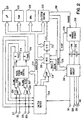
- Fig. 2 illustrates a functional schematic diagram of an implantable pacemaker/cardioverter/ defibrillator in which the invention may be practiced.
- Figures 3 - 7 illustrate the operation of an atrial rate stabilization feature of the preferred embodiment.
- Fig. 1 illustrates a defibrillator and lead set which may be used in realising the present invention.
- the ventricular lead includes an elongated insulative lead body 16, carrying three concentric coiled conductors, separated from one another by tubular insulative sheaths. Located adjacent the distal end of the lead are a ring electrode 24, an extendable helix electrode 26, mounted retractably within an insulative electrode head 28, and an elongated coil electrode 20. Each of the electrodes is coupled to one of the coiled conductors within the lead body 16. Electrodes 24 and 26 are employed for cardiac pacing and for sensing ventricular depolarizations.
- the defibrillation electrode 20 may be fabricated from platinum, platinum alloy or other materials known to be usable in implantable defibrillation electrodes and may be about 5 cm in length.
- the atrial/SVC lead includes an elongated insulative lead body 15, carrying three concentric coiled conductors, separated from one another by tubular insulative sheaths, corresponding to the structure of the ventricular lead. Located adjacent the J-shaped distal end of the lead are a ring electrode 21 and an extendable helix electrode 17, mounted retractably. within an insulative electrode head 19. Each of the electrodes is coupled to one of the coiled conductors within the lead body 15. Electrodes 17 and 21 are employed for atrial pacing and for sensing atrial depolarizations. An elongated coil electrode 23 is provided, proximal to electrode 21 and coupled to the third conductor within the lead body 15.
- Electrode 23 preferably is 10 cm in length or greater and is configured to extend from the SVC toward the tricuspid valve. In one preferred embodiment tested by the inventors, approximately 5 cm of the right atrium/SVC electrode was located in the right atrium, with the remaining 5 cm located in the SVC.
- a bifurcated connector 13 which carries three electrical connectors, each coupled to one of the coiled conductors.
- the coronary sinus lead includes an elongated insulative lead body 6, carrying one coiled conductor, coupled to an elongated coiled defibrillation electrode 8. Electrode 8, illustrated in broken outline, is located within the coronary sinus and great vein of the heart. At the proximal end of the lead is a connector plug 4 which carries an electrical connector, coupled to the coiled conductor.
- the coronary sinus/great vein electrode 8 may be about 5 cm in length.
- An implantable pacemaker/cardioverter/defibrillator 10 is shown in combination with the leads, with the lead connector assemblies 4, 13 and 14 inserted into the connector block 12.
- insulation of the outward facing portion of the housing 11 of the pacemaker/cardioverter/defibrillator 10 may be provided using a plastic coating, for example parylene or silicone rubber, as is currently employed in some unipolar cardiac pacemakers.
- the outward facing portion may instead be left uninsulated, or some other division between insulated and uninsulated portions may be employed.
- the uninsulated portion of the housing 11 optionally serves as a subcutaneous defibrillation electrode, used to defibrillate either the atria or ventricles.
- Atrial defibrillation and sensing electrodes might be added to either the coronary sinus lead or the right ventricular lead instead of being located on a separate atrial lead, allowing for a two-lead system.
- FIG. 2 is a functional schematic diagram of an implantable pacemaker/cardioverter/ defibrillator in which the present invention may usefully be practiced.
- This diagram should be taken as exemplary of the type of device in which the invention may be embodied, and not as limiting, as it is believed that the invention may usefully be practiced in a wide variety of device implementations, including devices providing therapies for treating atrial arrhythmias instead of or in addition to ventricular arrhythmias, cardioverters and defibrillators which do not provide antitachycardia pacing therapies, antitachycardia pacers which do not provide cardioversion or defibrillation, and devices which deliver different forms of anti-arrhythmia therapies such as nerve stimulation or drug administration.
- Electrode 311 corresponds to electrode 11, and is the uninsulated portion of the housing of the implantable pacemaker/cardioverter /defibrillator.
- Electrode 320 corresponds to electrode 20 and is a defibrillation electrode located in the right ventricle.
- Electrode 310 corresponds to electrode 8 and is a defibrillation electrode located in the coronary sinus.
- Electrode 318 corresponds to electrode 28 and is a defibrillation electrode located in the superior vena cava.
- Electrodes 324 and 326 correspond to electrodes 24 and 26, and are used for sensing and pacing in the ventricle.
- Electrodes 317 and 321 correspond to electrodes 19 and 21 and are used for pacing and sensing in the atrium.
- Electrodes 310 , 311, 318 and 320 are coupled to high voltage output circuit 234. Electrodes 324 and 326 are coupled to the R-wave amplifier 200, which preferably takes the form of an automatic gain controlled amplifier providing an adjustable sensing threshold as a function of the measured R-wave amplitude. A signal is generated on R-out line 202 whenever the signal sensed between electrodes 324 and 326 exceeds the present sensing threshold.
- Electrodes 317 and 321 are coupled to the P-wave amplifier 204. which preferably also takes the form of an automatic gain controlled amplifier providing an adjustable sensing threshold as a function of the measured R-wave amplitude. A signal is generated on P-out line 206 whenever the signal sensed between electrodes 317 and 321 exceeds the present sensing threshold.
- the general operation of the R-wave and P-wave amplifiers 200 and 204 may correspond to that disclosed in U.S. Patent No. 5,117,824, by Keimel, et al., issued June 2, 1992, for an Apparatus for Monitoring Electrical Physiologic Signals.
- Switch matrix 208 is used to select which of the available electrodes are coupled to wide band (0.5-200 Hz) amplifier 210 for use in digital signal analysis. Selection of electrodes is controlled by the microprocessor 224 via data/address bus 218, which selections may be varied as desired. Signals from the electrodes selected for coupling to bandpass amplifier 210 are provided to multiplexer 220, and thereafter converted to multi-bit digital signals by A/D converter 222, for storage in random access memory 226 under control of direct memory access circuit 228. Microprocessor 224 may employ digital signal analysis techniques to characterize the digitized signals stored in random access memory 226 to recognize and classify the patient's heart rhythm employing any of the numerous signal processing methodologies known to the art.
- the pacer timing/control circuitry 212 includes programmable digital counters which control the basic time intervals associated with DDD, VVI, DVI, VDD, AAI, DDI and other modes of single and dual chamber pacing well known to the art. Circuitry 212 also controls escape intervals associated with anti-tachyarrhythmia pacing in both the atrium and the ventricle, employing, any anti-tachyarrhythmia pacing therapies known to the art.
- Intervals defined by pacing circuitry 212 include atrial and ventricular pacing escape intervals, the refractory periods during which sensed P-waves and R-waves are ineffective to restart timing of the escape intervals and the pulse widths of the pacing pulses.
- the durations of these intervals are determined by microprocessor 224, in response to stored data in memory 226 and are communicated to the pacing circuitry 212 via address/data bus 218.
- Pacer circuitry 212 also determines the amplitude of the cardiac pacing pulses under control of microprocessor 224.
- the escape interval counters within pacer timing/control circuitry 212 are reset upon sensing of R-waves and P-waves as indicated by signals on lines 202 and 206, and in accordance with the selected mode of pacing on time-out trigger generation of pacing pulses by pacer output circuits 214 and 216, which are coupled to electrodes 317, 321, 324 and 326.
- the escape interval counters are also reset on generation of pacing pulses, and thereby control the basic timing of cardiac pacing functions, including anti-tachyarrhythmia pacing.
- the durations of the intervals defined by the escape interval timers are determined by microprocessor 224, via data/address bus 218.
- the value of the count present in the escape interval counters when reset by sensed R-waves and P-waves may be used to measure the durations of R-R intervals, P-P intervals, PR intervals and R-P intervals, which measurements are stored in memory 226 and used in conjunction with the present invention to diagnose the occurrence of a variety of tachyarrhythmias, as discussed in more detail below.
- Microprocessor 224 operates as an interrupt driven device, and is responsive to interrupts from pacer timing/control circuitry 212 corresponding to the occurrences of sensed P-waves and R-waves and corresponding to the generation of cardiac pacing pulses. These interrupts are provided via data/address bus 218. Any necessary mathematical calculations to be performed by microprocessor 224 and any updating of the values or intervals controlled by pacer timing/ control circuitry 212 take place following such interrupts.
- Microprocessor 224 includes associated ROM in which the stored program controlling its operation as described below resides. A portion of the memory 226 (Fig.
- 4) may be configured as a plurality of recirculating buffers, capable of holding series of measured intervals, which may be analyzed in response to the occurrence of a pace or sense interrupt to determine whether the patient's heart is presently exhibiting atrial or ventricular tachyarrhythmia.
- the arrhythmia detection method used by the present invention may include prior art tachyarrhythmia detection algorithms. As described below, the entire ventricular arrhythmia detection methodology of presently available Medtronic pacemaker/cardioverter/defibrillators is employed as part of the arrhythmia detection and classification method used by the disclosed preferred embodiment of the invention. However, any of the various arrhythmia detection methodologies known to the art, as discussed in the introduction above might also usefully be employed in alternative embodiments of the invention.
- timing intervals for controlling generation of anti-tachyarrhythmia pacing therapies are loaded from microprocessor 224 into the pacer timing and control circuitry 212, to control the operation of the escape interval counters therein and to define refractory periods during which detection of R-waves and P-waves is ineffective to restart the escape interval counters.
- circuitry for controlling the timing and generation of anti-tachycardia pacing pulses as described in U.S. Patent No. 4,577,633, issued to Berkovits et al on March 25, 1986, U.S. Patent No.
- microprocessor 224 In the event that generation of a cardioversion or defibrillation pulse is required, microprocessor 224 employs the escape interval counter to control timing of such cardioversion and defibrillation pulses, as well as associated refractory periods. In response to the detection of atrial or ventricular fibrillation or tachyarrhythmia requiring a cardioversion pulse, microprocessor 224 activates cardioversion/defibrillation control circuitry 230, which initiates charging of the high voltage capacitors 246, 248 via charging circuit 236, under control of high voltage charging control line 240.
- VCAP line 244 The voltage on the high voltage capacitors is monitored via VCAP line 244, which is passed through multiplexer 220 and in response to reaching a predetermined value set by microprocessor 224, results in generation of a logic signal on Cap Full (CF) line 254, terminating charging. Thereafter, timing of the delivery of the defibrillation or cardioversion pulse is controlled by pacer timing/control circuitry 212. Following delivery of the fibrillation or tachycardia therapy the microprocessor then returns the device to cardiac pacing and awaits the next successive interrupt due to pacing or the occurrence of a sensed atrial or ventricular depolarization.
- VCAP line 244 which is passed through multiplexer 220 and in response to reaching a predetermined value set by microprocessor 224, results in generation of a logic signal on Cap Full (CF) line 254, terminating charging.
- CF Cap Full
- high frequency pulse bursts may be delivered to electrodes 317 and 321 to terminate atrial tachyarrhythmias, as described in PCT Patent Publication No. WO95/28987, filed by Duffin et al and PCT Patent Publication No. WO95/28988, filed by Mehra et al.
- any known cardioversion or defibrillation pulse control circuitry is believed usable in conjunction with the present invention.
- circuitry controlling the timing and generation of cardioversion and defibrillation pulses as disclosed in U.S. Patent No. 4,384,585, issued to Zipes on May 24, 1983, in U.S. Patent No. 4,949,719 issued to Pless et al, cited above, and in U.S. Patent No. 4,375,817, issued to Engle et al.
- output circuit 234 determines whether a monophasic or biphasic pulse is delivered, whether the housing 311 serves as cathode or anode and which electrodes are involved in delivery of the pulse.
- An example of output circuitry for delivery of biphasic pulse regimens may be found in the above cited patent issued to Mehra and in U.S. Patent No. 4,727,877.
- circuitry which may be used to control delivery of monophasic pulses is set forth in commonly assigned U.S. Patent No. 5,163,427, by Keimel, issued November 17, 1992.
- output control circuitry as disclosed in U.S. Patent No. 4,953,551, issued to Mehra et al on September 4, 1990 or U.S. Patent No. 4,800,883, issued to Winstrom on January 31, 1989, may also be used in conjunction with a device embodying the present invention for delivery of biphasic pulses.
- an anti-tachycardia pacing therapy may be selected and delivered to the chamber in which the tachycardia is diagnosed or to both chambers.
- a more aggressive anti-tachycardia pacing therapy may be scheduled. If repeated attempts at anti-tachycardia pacing therapies fail, a higher level cardioversion pulse may be selected thereafter.
- Therapies for tachycardia termination may also vary with the rate of the detected tachycardia, with the therapies increasing in aggressiveness as the rate of the detected tachycardia increases. For example, fewer attempts at antitachycardia pacing may be undertaken prior to delivery of cardioversion pulses if the rate of the detected tachycardia is above a preset threshold.
- the references cited above in conjunction with descriptions of prior art tachycardia detection and treatment therapies are applicable here as well.
- the arrhythmia detection and classification system of the embodiment of the invention disclosed herein employs a prioritized set of inter-related rules for arrhythmia detection.
- Each rule contains a set of one or more "clauses" which must be satisfied (criteria which must be met). While all clauses of a rule are satisfied, the rule is indicated to be met. In the context of the present application this is referred to as the rule "firing". It is possible for multiple rules to be "firing" at the same time, with the highest priority rule taking precedence. Some rules trigger delivery of therapy when firing. Other rules inhibit delivery of therapy when firing. The highest priority rule firing at any specific time controls the behavior of the device. For example, the firing of a rule which triggers therapy is superseded by the firing of higher priority rules preventing delivery of therapy. Rules cease firing when their clauses cease to be satisfied, whether or not a therapy is triggered by the rule.
- Each rule includes a set of clauses or criteria which, when satisfied, indicate the likely occurrence of a specified type of heart rhythm, including various tachyarrhythmias, sinus tachycardia and normal sinus rhythm.
- a specific rhythm or tachyarrhythmia may have more than one associated rule.
- the rules are interrelated, such that progress toward meeting the requirements of a clause of one rule may also be the subject matter of a clause of a different rule.
- the present invention is directed toward the provision of an Atrial Rate Stabilization (ARS) pacing mode similar in some respects to that disclosed in the above-cited Mehra 471 patent.
- the rate stabilization mode is improved by providing for modified operation in the presence of refractory sensed atrial events and ventricular events occurring outside the device's defined AV escape intervals.
- the arrhythmia prevention pacing mode is particularly optimized for use in a dual chamber antitachyarrhythmia device.
- ARS is preferably programmable ON or OFF.
- ARS pacing is provided by the device in the same fashion as other pacing modalities, with the timing of escape intervals and refractory periods and the measurement of intervals between sensed and paced events accomplished by pacer timing and control circuitry 212, as described above and in WO 98/25669.
- Microprocessor 224 performs the requred calculations as described below, based on stored programming in its associated ROM and controls operation of the timers and associated logic in pacer timing and control circuitry 212.
- the various programmed and derived values described below are stored in RAM 226.
- ARS pacing is a pacing mode which eliminates long pauses following premature atrial beats by interpolating the long interval with an atrial paced beat with the goal of preventing or reducing the incidence of atrial tachyarrhythmias.
- the ARS mode like the rate stabilization mode describe in the above-cited Mehra patent eliminates the long pause and then gradually returns the atrial cycle length to the previous value by setting the atrial escape interval to the previous atrial cycle length plus a programmable ARS Interval Increment (AARS).
- AARS programmable ARS Interval Increment
- ARS is available when the permanent pacing mode is AAI or DDD.
- the atrial escape interval is set to the ARS interval (ARSI) which is computed from the measured previous A-A interval (AAlast), the programmed ARS Interval Increment (AARS), the programmed Lower Rate interval (LRIP) and the programmed Minimum ARS interval (ARSImin).
- ARSI interval is bounded to be greater than or equal to the ARSImin and less than or equal to the LR interval according to the following equation.
- ARSI Max[ARSImin,Min(AAlast+AARS, LRIP)].
- ARSI is set equal to the value of the previous A-A interval, paced or sensed, plus the programmed increment, so long as the sum is between the boundaries defined by LRIP and ARSImin, and is otherwise set equal to LRIP or ARSImin.
- Atrial Rate Stabilization feature corresponds exactly to the operation of the rate stabilization pacing mode set forth in the above-cited Mehra patent. If AAlast is unknown, for example following therapy or following the ARS pacing mode either being programmed ON, the ARSI will be LRIP.
- ARS is not supported in DDI mode using the specific atrial escape interval calculation method diclosed herein because atrial sensed events in DDI do not initiate atrial escape intervals.
- the basic improvements to rate stabilization pacing disclosed herein are applicable to DDI pacing, with the modification that the V-A escape interval would be adjusted, based on previous A-A intervals, with a corresponding correction for the programmed SAV and/or PAV intervals.
- the V-A escape interval could be set equal to AAlast - PAV + AARS, with other aspects of the interval timing methodology adjusted accordingly.
- an alternative method of calculating ARSI is to set it equal to Min[LRIP, Max(AAlast + AARS, ARSImin)], which will allow ARSImin to be less than the sensor-indicated LRIP without over-riding LRIP.
- the ARSI atrial escape interval in effect is canceled and the atrial escape interval (from the preceding non-refractory sensed atrial depolarization or atrial pacing pulse) is set to LRIP. This occurs in both AAI and DDD modes.
- the 'effective' Minimum ARS Interval is the atrial refractory period (ARP) plus AARS in AAI mode and the total atrial refractory period (TARP) Plus AARS in DDD mode.
- TARP in DDD mode is typically about 450 ms. In some patients, this may be too long for ARS to be effective. In these cases a shorter PVARP will have to be programmed if ARS pacing is desired.
- the ARP and TARP define minimum coupling intervals for sensed atrial events to which ARS pacing is applied. ARSmin limits the resulting atrial pacing escape interval.
- a long programmed TARP or ARP could functionally over-ride a short programmed ARSmin, and users should therefore program these two parameters in a coordinated fashion.
- the microprocessor prevents programming of ARSImin to be less than VTDI, as defined above, if VT Detection is ON, or less than VFDI, as defined above, if VF Detection is ON. These interlocks guard against atrial pacing cross talk to the ventricular sense amplifier resulting in inappropriate detection of VT or VF.
- Ventricular events sensed within the programmed, PAV and SAV intervals and ventricular pacing pulses delivered at the ends of the PAV and SAV intervals have no affect on timing of the ARSI underway.
- the effect of a ventricular sensed event, such as a PVC, outside the PAV or SAV interval in DDD mode depends upon the timing of the sensed ventricular event relative to expiration of the ARSI underway. If the ARSI underway expires at least 100 ms following expiration of the PVARP initiated by the sensed ventricular event, the ARSI underway is unaffected. If the ARSI underway expires sooner, it is lengthened to expire 100 ms following the end of PVARP.
- ARSI is set equal to LRIP minus PAV. If the SAV interval is extended to the expiration of UTRI, as occurs during "pseudo-Wenckebach" upper rate behavior, as described in U.S. Patent No.4,059,116, issued to Adams, a sensed depolarization occurring during the extension past the programmed value of SAV is considered to occur outside the SAV interval, and is treated as discussed above. A ventricular pacing pulse delivered at the end of an extended SAV interval is also treated the same as a sensed depolarization outside of the SAV interval.
- the ARS pacing mode is preferably automatically activated and deactivated, as opposed to being continuously in effect. If programmed ON, ARS pacing remains in effect unless suspended or programmed OFF. ARS is suspended if the RR median interval, as defined above, is less than the VTDI if VT detection is ON or is less than the VFDI if VF detection is ON, or the AT/AF sustained duration timer, as defined above, is non-zero, or a detected VT or VF episode is in progress, or a therapy or capacitor charging is in progress. When ARS is suspended the atrial escape interval following non-refractory atrial events is LRlP, the same as if ARS is OFF. When ARS pacing resumes from a suspended condition the AAlast will be unknown, with the result that the first ARS interval is set equal to LRIP, as discussed above. This prevents atrial events during the suspended condition from affecting ARS operation.
- FIG. 3 normal operation of ARS pacing in DDD mode is illustrated.
- the timing of the atrial escape interval ARSI0 (802) is halted, the ARSI1 cycle length (804) is calculated and is set equal to the preceding A-A interval AA0 (806) plus AARS.
- the scheduled ventricular pacing pulse on expiration of the SAV escape interval 810 is cancelled, and PVARP 812 is initiated.
- an atrial pacing pulse is delivered at 814, and ARSI2 (816) is set equal to the preceding A-A interval AA1 (818) plus AARS.
- a ventricular pacing pulse is delivered at 820, on expiration of the PAV escape interval 822 and PVARP 824 is initiated.
- ARSI would be gradually incremented to LRIP.
- a non-refractory atrial depolarization is sensed prior to ARS time-out, causing the value of ARSI3 (828) to be set to the preceding A-A interval AA2 (830) plus AARS.
- the effect of non-refractory atrial depolarizations in AAI mode is the same.
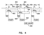
- Figure 4 illustrates the operation of ARS pacing in DDD mode, in response to a refractory sensed atrial depolarization.
- a non-refractory atrial depolarization is sensed, causing timing of the atrial escape interval ARSI0 (852) underway to be halted and ARSI1 (854)to be set to the preceding A-A interval AA0 (856) plus AARS.
- ARSI0 atrial escape interval
- ARSI1 ARSI1
- a ventricular pacing pulse is generated.
- an atrial depolarization is sensed within the PVARP 864.
- AAlast is set equal to AA1 (866) and the atrial escape interval is modified so that the next atrial pacing pulse is scheduled to occur on expiration of LRIP - AAlast (868) from refractory sensed atrial event 862, so that the next atrial pacing pulse is effectively scheduled to occur at LRIP following non-refractory sensed atrial event 850.
- a non-refractory atrial depolarization is sensed starting timing of ARSI2 (872), which is set equal to AA2 plus AARS.
- refractory sensed atrial depolarization 862 does not initiate timing of an ARSI, it is nonetheless employed for measuring the A-A interval to derive the value of AAlast.
- the effect of refractory sensed atrial depolarizations in AAI mode is the same.
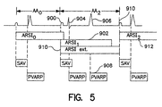
- FIG. 5 illustrates the operation of ARS pacing in DDD mode in response to the occurrence of PVC's or other ventricular events which occur outside of a PAV or SAV escape interval.
- an atrial event is sensed, initiating timing of ARSI1 (902).
- a ventricular depolarization is sensed, followed by a PVC at 906, initiating timing of a new PVARP 908, in this case equal to PVARPpvc.
- ARSI1 expires less than 100 ms following the expiration of the PVARP 908, ARSI1 is extended at 910 to expire 100 ms following expiration of the PVARP 908.
- ARSI1 would have expired 100 ms or more following expiration of PVARP 908, the duration of ARSI1 would not have been affected by the occurrence of the PVC.
- an atrial pacing pulse is delivered at 910, with ASRI2 (912) calculated based on AA2, which is equal to the extended duration of ASRI1.
- Figure 6 illustrates the effect of refractory sensed atrial events in conjunction with ventricular sensed events outside of the SAV and PAV intervals.
- a refractory sensed atrial event occurs, canceling timing of ARSI0 (922) as discussed above and resetting the atrial escape interval at 924 to expire at LRIP as measured from preceding non-refractory sensed atrial depolarization 926 as discussed above.
- a ventricular event is sensed, outside of the preceding SAV interval 930. Because ARSI0 (932) was previously cancelled by the refractory sensed atrial event 920, the next atrial pacing pulse is rescheduled to LRIP - PAV (934) following the sensed ventricular event 928.
- a non-refractory atrial event is sensed, canceling timing of the atrial escape interval in effect and setting ARSI1 (936)equal to the A-A interval AA1 plus AARS.
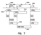
- FIG. 7 illustrates the effect of ventricular events occurring during extended SAV intervals.
- a non-refractory atrial event occurs, which terminates timing of ARSI0 (942) and sets ARSI1 (944) equal to AA0 (945) plus AARS.
- the SAV interval 946 would expire prior to UTRI 948, it is extended until expiration of UTRI.
- a ventricular depolarization is sensed, in the extended portion of the extended SAV interval 946 , and, as discussed above, it is treated as occurring outside of the SAV interval, resetting timing of the atrial escape interval to LRIP - PAV at 952, as timed from ventricular depolarization 950.
- a non-refractory atrial event is sensed, canceling timing of the atrial escape interval in effect and setting ARSI2 equal to the A-A interval AA1 (956) plus AARS.
- diagnostic data may optionally be recorded in RAM by the microprocessor, related to the operation of the ARS pacing feature.
- the microprocessor may be programmed to define an ARS Counter which counts the number of contiguous runs of ARS pacing since the counter was last reset. When ARS is ON the ARS Counter could be incremented on an atrial paced event if the preceding atrial event is a non-refractory sense, and the measured atrial sense to atrial pace (A-A interval) is less than the LRIP, and the measured A-A interval is equal to the ARSI calculated for the preceding atrial sense.
- a log (ARSLOG) of the most recent 25 times that ARS was activated may also be saved in RAM by the microprocessor.
- This log may include a time stamp, the number of consecutive ARS paces (i.e. consecutive atrial pace intervals less than the low rate interval), and intervals and markers for the 10 events prior to and 10 events following the first ARS pace.
- a buffer memory defined in RAM could give the number of ARS counts by the hour for a predetermined preceding period, or an atrial cycle length histogram based on the 5 A-A intervals before the ARS Counter is incremented could similarly be derived by the microprocessor and saved in RAM.
- the arrhythmia prevention pacing mode is also believed workable in conjunction with other arrhythmia detection methodologies, such as those disclosed in the above-cited WO92/18198 application by Adams et al and the above-cited 005 Pless et al patent, 006 Haluska et al patent, 402 Olson et al patent, 380 Vollman et al patent and 508 Gunderson patent, in which a measure of the intrinsic atrial or ventricular rate is provided and may similarly be employed to deactivate the arrhythmia prevention pacing mode.
- the arrhythmia prevention mode is included in a dual chamber pacemaker which does not include anti-arrhythmia therapies, a measurement of ventricular or atrial rate can still usefully be employed to activate and deactivate the arrhythmia prevention pacing mode.
- the disclosed embodiment of the invention includes an optimized method for responding to refractory sensed atrial depolarizations, an optimized method for responding to ventricular events occurring outside the device's defined AV escape intervals and a preferred method of activating and deactivating the arrhythmia pacing mode, each of these features is believed useful and valuable if employed individually.
- the improved response to refractory sensed depolarizations in the atrium is useful by itself in an AAI pacer. It is similarly believed that corresponding use of this feature to regulate escape intervals in a VVI pacer, in response to refractory sensed depolarizations in the ventricle is also valuable.
Description
Claims (4)
- A cardiac pacemaker, comprising:a sense amplifier (200, 204), responsive to depolarizations of a chamber of a heart;a pulse generator (10);interval determining means (212) responsive to the pulse generator and the sense amplifier for determining heartbeat intervals separating sensed depolarizations and generated pacing pulses in said chamber;refractory means for defining refractory periods; andcontrol means (224) responsive to the heartbeat interval determining means for defining escape intervals following generated sensed depolarizations outside of said refractory periods, said escape intervals being set, according to a first method, to an interval equal to the value of the directly atrial preceding heartbeat interval (AAlast) plus a pre-programmed increment (AARS) so long as the sum is between a lower programmed atrial pacing rate interval and a programmed minimum atrial rate (ARSImin), and is otherwise set to the lower programmed atrial pacing rate interval (LRIP) or the programmed minimum atrial rate (ARSImin), and comprising means for triggering the pulse generator on expirations of the defined escape intervals; characterized in thatthe control means further comprises means responsive to the sense amplifier and the refractory means for defining atrial escape intervals following atrial depolarizations sensed during said atrial refractory periods, said atrial escape intervals being set, according to a second, different method, to an interval equal to said lower programmed pacing rate interval (LRIP) minus said directly preceding atrial heartbeat interval (AAlast).
- A cardiac pacemaker according to claim 1, wherein:said sense amplifier is an atrial sense amplifier (204), responsive to atrial depolarizations;said pulse generator is an atrial pulse generator;said interval determining means is an A-A interval determination means responsive to the atrial pulse generator and the atrial sense amplifier for determining A-A intervals separating sensed atrial depolarizations and generated atrial pacing pulses;said pacemaker further comprises a ventricular sense amplifier (200) responsive to ventricular depolarizations and PVC detection means responsive to the ventricular sense amplifier for detecting PVCs;said refractory means comprises means responsive to the PVC detection means for defining atrial refractory periods following detections of PVCs, andsaid control means further comprises means responsive to the PVC detection means for comparing the A-A escape interval underway to the atrial refractory period following the detected PVC and extending the A-A interval underway if it expires less than a defined interval following the atrial refractory period.
- A cardiac pacemaker according to claim 1, wherein:said sense amplifier is an atrial sense amplifier (204), responsive to atrial depolarizations;said pulse generator is an atrial pulse generator;said interval determining means comprises A-A interval determination means responsive to the atrial pulse generator and the atrial sense amplifier for determining A-A intervals separating sensed atrial depolarizations and generated atrial pacing pulses;said pacemaker further comprises a ventricular sense amplifier (200) responsive to ventricular depolarizations; andsaid refractory means is responsive to the ventricular sense amplifier for defining atrial refractory periods following detections of ventricular depolarizations.
- A cardiac pacemaker according to any of claims 1 to 3, further comprising:wherein said control means comprises means responsive to said arrhythmia detection means for defining escape intervals equal to said base pacing intervals in response to detection of heart rhythms consistent with tachyarrhythmia.means for defining base pacing intervals;arrhythmia detection means for detecting heart rhythms consistent with tachyarrhythmia, and
Applications Claiming Priority (3)
| Application Number | Priority Date | Filing Date | Title |
|---|---|---|---|
| US08/764,568 US5846263A (en) | 1996-12-13 | 1996-12-13 | Apparatus for diagnosis and treatment of arrhythmias |
| US764568 | 1996-12-13 | ||
| PCT/US1997/023061 WO1998025670A1 (en) | 1996-12-13 | 1997-12-10 | Method and apparatus for diagnosis and treatment of arrhythmias |
Publications (2)
| Publication Number | Publication Date |
|---|---|
| EP1015073A1 EP1015073A1 (en) | 2000-07-05 |
| EP1015073B1 true EP1015073B1 (en) | 2003-11-12 |
Family
ID=25071098
Family Applications (1)
| Application Number | Title | Priority Date | Filing Date |
|---|---|---|---|
| EP97952442A Expired - Lifetime EP1015073B1 (en) | 1996-12-13 | 1997-12-10 | Apparatus for diagnosis and treatment of arrhythmias |
Country Status (5)
| Country | Link |
|---|---|
| US (1) | US5846263A (en) |
| EP (1) | EP1015073B1 (en) |
| AU (1) | AU5604298A (en) |
| DE (1) | DE69726195T2 (en) |
| WO (1) | WO1998025670A1 (en) |
Cited By (1)
| Publication number | Priority date | Publication date | Assignee | Title |
|---|---|---|---|---|
| US9533156B2 (en) | 2012-10-31 | 2017-01-03 | Medtronic, Inc. | Method for calculating an estimate of a time-varying physiological variable |
Families Citing this family (77)
| Publication number | Priority date | Publication date | Assignee | Title |
|---|---|---|---|---|
| US8036741B2 (en) | 1996-04-30 | 2011-10-11 | Medtronic, Inc. | Method and system for nerve stimulation and cardiac sensing prior to and during a medical procedure |
| US6195420B1 (en) * | 1996-06-26 | 2001-02-27 | Sun Microsystems, Inc. | Hotel check-out system |
| US6415180B1 (en) | 1997-04-04 | 2002-07-02 | Cardiac Pacemakers, Inc. | Device and method for ventricular tracking and pacing |
| FR2764810B1 (en) * | 1997-06-20 | 1999-08-13 | Ela Medical Sa | DEVICE AND METHOD FOR THE TREATMENT OF EAR RHYTHM DISORDERS |
| US6479523B1 (en) | 1997-08-26 | 2002-11-12 | Emory University | Pharmacologic drug combination in vagal-induced asystole |
| EP1105188B1 (en) | 1998-08-17 | 2005-05-25 | Medtronic, Inc. | apparatus for prevention of atrial tachyarrhythmias |
| US6205357B1 (en) | 1998-12-04 | 2001-03-20 | Uab Research Foundation | Methods and apparatus for detecting and treating medical conditions of the heart |
| US6434424B1 (en) | 1998-12-28 | 2002-08-13 | Medtronic, Inc. | Regularization of ventricular rate during atrial tachyarrhythmia |
| US6167308A (en) * | 1999-04-09 | 2000-12-26 | Medtronic, Inc. | Closed loop ATP |
| US6240313B1 (en) * | 1999-04-19 | 2001-05-29 | Cardiac Pacemakers, Inc. | Cardiac rhythm management system with prevention of double counting of events |
| US7181278B2 (en) | 1999-05-21 | 2007-02-20 | Cardiac Pacemakers, Inc. | Apparatus and method for ventricular rate regularization |
| US6285907B1 (en) | 1999-05-21 | 2001-09-04 | Cardiac Pacemakers, Inc. | System providing ventricular pacing and biventricular coordination |
| US6351669B1 (en) | 1999-05-21 | 2002-02-26 | Cardiac Pacemakers, Inc. | Cardiac rhythm management system promoting atrial pacing |
| US8064997B2 (en) | 1999-05-21 | 2011-11-22 | Cardiac Pacemakers, Inc. | Method and apparatus for treating irregular ventricular contractions such as during atrial arrhythmia |
| US6501988B2 (en) | 2000-12-26 | 2002-12-31 | Cardiac Pacemakers Inc. | Apparatus and method for ventricular rate regularization with biventricular sensing |
| US6430438B1 (en) | 1999-05-21 | 2002-08-06 | Cardiac Pacemakers, Inc. | Cardiac rhythm management system with atrial shock timing optimization |
| US7212860B2 (en) | 1999-05-21 | 2007-05-01 | Cardiac Pacemakers, Inc. | Apparatus and method for pacing mode switching during atrial tachyarrhythmias |
| US7142918B2 (en) | 2000-12-26 | 2006-11-28 | Cardiac Pacemakers, Inc. | Apparatus and method for pacing mode switching during atrial tachyarrhythmias |
| US6442429B1 (en) | 1999-06-18 | 2002-08-27 | Medtronic, Inc. | Method and apparatus for diagnosis and treatment of arrhythmias |
| JP2003503119A (en) | 1999-06-25 | 2003-01-28 | エモリ ユニバーシティ | Vagal nerve stimulation device and method |
| US6272380B1 (en) * | 1999-08-19 | 2001-08-07 | Medtronic, Inc. | Apparatus for treating atrial tachy arrhythmias with synchronized shocks |
| US6400986B1 (en) | 2000-04-10 | 2002-06-04 | Cardiac Pacemakers, Inc. | Adaptive anti-tachycardia therapy apparatus and method |
| US6556859B1 (en) * | 2000-04-24 | 2003-04-29 | Medtronic, Inc. | System and method for classifying sensed atrial events in a cardiac pacing system |
| US7039461B1 (en) | 2000-05-13 | 2006-05-02 | Cardiac Pacemakers, Inc. | Cardiac pacing system for prevention of ventricular fibrillation and ventricular tachycardia episode |
| US8512220B2 (en) | 2000-05-26 | 2013-08-20 | Cardiac Pacemakers, Inc. | Rate smoothing control |
| US6424865B1 (en) | 2000-07-13 | 2002-07-23 | Cardiac Pacemakers, Inc. | Ventricular conduction delay trending system and method |
| US6512951B1 (en) | 2000-09-14 | 2003-01-28 | Cardiac Pacemakers, Inc. | Delivery of atrial defibrillation shock based on estimated QT interval |
| US6829504B1 (en) | 2000-09-14 | 2004-12-07 | Cardiac Pacemakers, Inc. | System and method for preventing recurrence of atrial tachyarrhythmia |
| US6978177B1 (en) | 2000-11-14 | 2005-12-20 | Cardiac Pacemakers, Inc. | Method and apparatus for using atrial discrimination algorithms to determine optimal pacing therapy and therapy timing |
| US6957100B2 (en) | 2000-12-26 | 2005-10-18 | Cardiac Pacemakers, Inc. | Method and system for display of cardiac event intervals in a resynchronization pacemaker |
| US20040204985A1 (en) * | 2001-02-09 | 2004-10-14 | Gibson Donald P. | Digital image service and revenue generation |
| US6498949B2 (en) * | 2001-02-27 | 2002-12-24 | Pacesetter, Inc. | Implantable cardiac device providing repetitive non-reentrant ventriculo-atrial synchronous (RNRVAS) rhythm therapy using VA interval extension and method |
| US6963776B2 (en) | 2001-04-05 | 2005-11-08 | Cardiac Pacemakers, Inc. | Cardiac rhythm management system synchronizing atrial shock to ventricular depolarization based on length of sensing refractory |
| US6904319B2 (en) * | 2001-04-06 | 2005-06-07 | Cardiac Pacemakers, Inc. | Method and apparatus for inhibiting atrial tachyarrhythmia therapy |
| US6775572B2 (en) | 2001-10-25 | 2004-08-10 | Cardiac Pacemakers, Inc. | Method and system for automatic anti-tachycardia pacing |
| US6885890B2 (en) * | 2001-12-20 | 2005-04-26 | Cardiac Pacemakers, Inc. | Apparatus and method for multi-site anti-tachycardia pacing |
| US6909916B2 (en) | 2001-12-20 | 2005-06-21 | Cardiac Pacemakers, Inc. | Cardiac rhythm management system with arrhythmia classification and electrode selection |
| US7158827B2 (en) * | 2002-04-22 | 2007-01-02 | Medtronic, Inc. | Ventricular rate stabilization |
| DE10245852B4 (en) * | 2002-09-30 | 2007-04-05 | Biotronik Gmbh & Co. Kg | Pacemaker for atrial sensing, atrial pacing and termination of atrial tachycardia and atrial fibrillation |
| US20040073261A1 (en) * | 2002-10-09 | 2004-04-15 | Kroll Mark W. | Methods and systems for treating ventricular fibrillation |
| US8192358B2 (en) * | 2003-04-22 | 2012-06-05 | Patrick Leahy | Device and method for use in surgery |
| GB2404832A (en) * | 2003-08-09 | 2005-02-16 | Black & Decker Inc | Safety mechanism for power tool |
| US7496402B2 (en) * | 2004-04-29 | 2009-02-24 | Cardiac Pacemakers, Inc. | ATP pacing with entrainment monitoring |
| US7616994B2 (en) | 2004-05-24 | 2009-11-10 | Cardiac Pacemakers, Inc. | Fast post-antitachycardia pacing redetection algorithm |
| US7894893B2 (en) | 2004-09-30 | 2011-02-22 | Cardiac Pacemakers, Inc. | Arrhythmia classification and therapy selection |
| US7228173B2 (en) | 2004-11-23 | 2007-06-05 | Cardiac Pacemakers, Inc. | Cardiac tachyarrhythmia therapy selection based on patient response information |
| US7280869B2 (en) * | 2004-12-03 | 2007-10-09 | Medtronic, Inc. | Arrhythmia termination detection based on beat pattern |
| US7818056B2 (en) | 2005-03-24 | 2010-10-19 | Cardiac Pacemakers, Inc. | Blending cardiac rhythm detection processes |
| US7908001B2 (en) | 2005-08-23 | 2011-03-15 | Cardiac Pacemakers, Inc. | Automatic multi-level therapy based on morphologic organization of an arrhythmia |
| US7653431B2 (en) | 2005-12-20 | 2010-01-26 | Cardiac Pacemakers, Inc. | Arrhythmia discrimination based on determination of rate dependency |
| US7742812B2 (en) * | 2006-03-29 | 2010-06-22 | Medtronic, Inc. | Method and apparatus for detecting arrhythmias in a medical device |
| US7738950B2 (en) | 2006-09-13 | 2010-06-15 | Cardiac Pacemakers, Inc. | Method and apparatus for identifying potentially misclassified arrhythmic episodes |
| US7873414B2 (en) * | 2007-04-17 | 2011-01-18 | Cardiac Pacemakers, Inc. | Patient characteristic based adaptive anti-tachy pacing programming |
| US20090149904A1 (en) | 2007-12-11 | 2009-06-11 | Cardiac Pacemakers, Inc. | Lv unipolar sensing or pacing vector |
| US20090157133A1 (en) | 2007-12-13 | 2009-06-18 | Cardiac Pacemakers, Inc. | Supraventricular tachy sensing vector |
| US8706220B2 (en) * | 2008-04-09 | 2014-04-22 | Medtronic, Inc. | Method and apparatus for detecting and treating tachyarrhythmias incorporating diagnostic/therapeutic pacing techniques |
| US8560069B2 (en) * | 2010-01-05 | 2013-10-15 | Siemens Medical Solutions Usa, Inc. | System for cardiac arrhythmia detection |
| US8620425B2 (en) | 2010-04-29 | 2013-12-31 | Medtronic, Inc. | Nerve signal differentiation in cardiac therapy |
| US8639327B2 (en) | 2010-04-29 | 2014-01-28 | Medtronic, Inc. | Nerve signal differentiation in cardiac therapy |
| US8406868B2 (en) | 2010-04-29 | 2013-03-26 | Medtronic, Inc. | Therapy using perturbation and effect of physiological systems |
| US8781582B2 (en) | 2011-01-19 | 2014-07-15 | Medtronic, Inc. | Vagal stimulation |
| US8718763B2 (en) | 2011-01-19 | 2014-05-06 | Medtronic, Inc. | Vagal stimulation |
| US8706223B2 (en) | 2011-01-19 | 2014-04-22 | Medtronic, Inc. | Preventative vagal stimulation |
| US8781583B2 (en) | 2011-01-19 | 2014-07-15 | Medtronic, Inc. | Vagal stimulation |
| US8725259B2 (en) | 2011-01-19 | 2014-05-13 | Medtronic, Inc. | Vagal stimulation |
| US9050014B2 (en) | 2011-12-14 | 2015-06-09 | Siemens Medical Solutions Usa, Inc. | System for cardiac arrhythmia detection and characterization |
| US10376705B2 (en) | 2014-04-01 | 2019-08-13 | Medtronic, Inc. | Method and apparatus for discriminating tachycardia events in a medical device |
| US9526908B2 (en) | 2014-04-01 | 2016-12-27 | Medtronic, Inc. | Method and apparatus for discriminating tachycardia events in a medical device |
| US9808640B2 (en) | 2014-04-10 | 2017-11-07 | Medtronic, Inc. | Method and apparatus for discriminating tachycardia events in a medical device using two sensing vectors |
| US9352165B2 (en) | 2014-04-17 | 2016-05-31 | Medtronic, Inc. | Method and apparatus for verifying discriminating of tachycardia events in a medical device having dual sensing vectors |
| US10244957B2 (en) | 2014-04-24 | 2019-04-02 | Medtronic, Inc. | Method and apparatus for selecting a sensing vector configuration in a medical device |
| US10278601B2 (en) | 2014-04-24 | 2019-05-07 | Medtronic, Inc. | Method and apparatus for selecting a sensing vector configuration in a medical device |
| US9795312B2 (en) | 2014-04-24 | 2017-10-24 | Medtronic, Inc. | Method and apparatus for adjusting a blanking period for selecting a sensing vector configuration in a medical device |
| US10252067B2 (en) | 2014-04-24 | 2019-04-09 | Medtronic, Inc. | Method and apparatus for adjusting a blanking period during transitioning between operating states in a medical device |
| US9610025B2 (en) | 2014-07-01 | 2017-04-04 | Medtronic, Inc. | Method and apparatus for verifying discriminating of tachycardia events in a medical device having dual sensing vectors |
| US10449364B2 (en) * | 2016-10-28 | 2019-10-22 | Medtronic, Inc. | Pacemaker mediated tachycardia detection and intervention |
| US10555684B2 (en) * | 2017-04-25 | 2020-02-11 | Medtronic, Inc. | Supraventricular tachyarrhythmia discrimination |
Family Cites Families (9)
| Publication number | Priority date | Publication date | Assignee | Title |
|---|---|---|---|---|
| US4577633A (en) | 1984-03-28 | 1986-03-25 | Medtronic, Inc. | Rate scanning demand pacemaker and method for treatment of tachycardia |
| US4941471A (en) * | 1988-09-07 | 1990-07-17 | Medtronic, Inc. | Rate stabilization pacemaker |
| US4971471A (en) | 1988-09-07 | 1990-11-20 | Sloan David B | Disposable mop |
| US5117824A (en) | 1990-11-14 | 1992-06-02 | Medtronic, Inc. | Apparatus for monitoring electrical physiologic signals |
| FR2669829B1 (en) * | 1990-11-30 | 1996-09-13 | Ela Medical Sa | CALCULATION PROCESS OF THE EXHAUST INTERVAL AT THE END OF WHICH, IT IS NECESSARY TO STIMULATE THE HEART OF A HEART IN THE ABSENCE OF DEPOLARIZATION. |
| FR2669828B1 (en) * | 1990-11-30 | 1993-02-12 | Ela Medical Sa | METHOD FOR CONTROLLING A DOUBLE CHAMBER HEART STIMULATOR. |
| US5403356A (en) * | 1993-04-28 | 1995-04-04 | Medtronic, Inc. | Method and apparatus for prevention of atrial tachy arrhythmias |
| US5480413A (en) * | 1994-11-30 | 1996-01-02 | Telectronics Pacing Systems, Inc. | Apparatus and method for stabilizing the ventricular rate of a heart during atrial fibrillation |
| US5545185A (en) * | 1994-12-23 | 1996-08-13 | Stephen Denker | Cardiac pacer which compensates for effects of abrupt changes in heart rate |
-
1996
- 1996-12-13 US US08/764,568 patent/US5846263A/en not_active Expired - Lifetime
-
1997
- 1997-12-10 DE DE69726195T patent/DE69726195T2/en not_active Expired - Lifetime
- 1997-12-10 WO PCT/US1997/023061 patent/WO1998025670A1/en active IP Right Grant
- 1997-12-10 AU AU56042/98A patent/AU5604298A/en not_active Abandoned
- 1997-12-10 EP EP97952442A patent/EP1015073B1/en not_active Expired - Lifetime
Cited By (2)
| Publication number | Priority date | Publication date | Assignee | Title |
|---|---|---|---|---|
| US9533156B2 (en) | 2012-10-31 | 2017-01-03 | Medtronic, Inc. | Method for calculating an estimate of a time-varying physiological variable |
| US9895544B2 (en) | 2012-10-31 | 2018-02-20 | Medtronic, Inc. | Method for calculating an estimate of a time-varying physiological variable |
Also Published As
| Publication number | Publication date |
|---|---|
| WO1998025670A1 (en) | 1998-06-18 |
| DE69726195T2 (en) | 2004-08-19 |
| AU5604298A (en) | 1998-07-03 |
| EP1015073A1 (en) | 2000-07-05 |
| DE69726195D1 (en) | 2003-12-18 |
| US5846263A (en) | 1998-12-08 |
Similar Documents
| Publication | Publication Date | Title |
|---|---|---|
| EP1015073B1 (en) | Apparatus for diagnosis and treatment of arrhythmias | |
| EP1077740B1 (en) | Atrial anti-arrhythmia pacemaker | |
| US5893882A (en) | Method and apparatus for diagnosis and treatment of arrhythmias | |
| US6091988A (en) | Apparatus for treating atrial tachyarrhythmias with synchronized shocks | |
| EP1194183B1 (en) | Diagnosis and treatment of arrhythmias | |
| US5968079A (en) | Method and apparatus for diagnosis and treatment of arrhythmias | |
| US6272380B1 (en) | Apparatus for treating atrial tachy arrhythmias with synchronized shocks | |
| US5840079A (en) | Method and apparatus for treatment of atrial fibrillation | |
| EP1622678B1 (en) | System for elimination of ventricular pro-arrhythmic effect caused by atrial therapy | |
| US6081745A (en) | Method and apparatus for treatment of arrhythmias | |
| US6988000B2 (en) | Forced deceleration algorithm for synchronization of atrial cardioversion shock and technique for the implementation | |
| EP1150742B1 (en) | Implantation device with automatic sensing adjustment | |
| EP0759309A2 (en) | Device and algorithm for a combined cardiomyostimulator and a cardiac pacer-cardioverter-defibrillator | |
| CA2139656A1 (en) | Atrial defibrillator employing transvenous and subcutaneous electrodes and method of use | |
| WO2001070104A2 (en) | Method and apparatus for diagnosis and treatment of arrhythmias | |
| US6484058B1 (en) | Methods for sensing arrhythmias in a pacemaker/defibrillator and a pacemaker/defibrillator programmed to implement the same | |
| US6058327A (en) | Implantable device with automatic sensing adjustment | |
| WO2005107861A1 (en) | Atp pacing with entrainment monitoring | |
| US7313438B2 (en) | Selective chamber ATP pacing |
Legal Events
| Date | Code | Title | Description |
|---|---|---|---|
| PUAI | Public reference made under article 153(3) epc to a published international application that has entered the european phase |
Free format text: ORIGINAL CODE: 0009012 |
|
| 17P | Request for examination filed |
Effective date: 19990622 |
|
| AK | Designated contracting states |
Kind code of ref document: A1 Designated state(s): DE FR GB IT NL SE |
|
| 17Q | First examination report despatched |
Effective date: 20021007 |
|
| GRAH | Despatch of communication of intention to grant a patent |
Free format text: ORIGINAL CODE: EPIDOS IGRA |
|
| RTI1 | Title (correction) |
Free format text: APPARATUS FOR DIAGNOSIS AND TREATMENT OF ARRHYTHMIAS |
|
| GRAA | (expected) grant |
Free format text: ORIGINAL CODE: 0009210 |
|
| GRAS | Grant fee paid |
Free format text: ORIGINAL CODE: EPIDOSNIGR3 |
|
| AK | Designated contracting states |
Kind code of ref document: B1 Designated state(s): DE FR GB IT NL SE |
|
| REG | Reference to a national code |
Ref country code: GB Ref legal event code: FG4D |
|
| PGFP | Annual fee paid to national office [announced via postgrant information from national office to epo] |
Ref country code: SE Payment date: 20031126 Year of fee payment: 7 |
|
| REF | Corresponds to: |
Ref document number: 69726195 Country of ref document: DE Date of ref document: 20031218 Kind code of ref document: P |
|
| REG | Reference to a national code |
Ref country code: SE Ref legal event code: TRGR |
|
| ET | Fr: translation filed | ||
| RAP2 | Party data changed (patent owner data changed or rights of a patent transferred) |
Owner name: MEDTRONIC, INC. |
|
| PLBE | No opposition filed within time limit |
Free format text: ORIGINAL CODE: 0009261 |
|
| STAA | Information on the status of an ep patent application or granted ep patent |
Free format text: STATUS: NO OPPOSITION FILED WITHIN TIME LIMIT |
|
| NLT2 | Nl: modifications (of names), taken from the european patent patent bulletin |
Owner name: MEDTRONIC, INC. |
|
| 26N | No opposition filed |
Effective date: 20040813 |
|
| PG25 | Lapsed in a contracting state [announced via postgrant information from national office to epo] |
Ref country code: SE Free format text: LAPSE BECAUSE OF NON-PAYMENT OF DUE FEES Effective date: 20041211 |
|
| EUG | Se: european patent has lapsed | ||
| PGFP | Annual fee paid to national office [announced via postgrant information from national office to epo] |
Ref country code: GB Payment date: 20051104 Year of fee payment: 9 |
|
| PGFP | Annual fee paid to national office [announced via postgrant information from national office to epo] |
Ref country code: NL Payment date: 20061108 Year of fee payment: 10 |
|
| GBPC | Gb: european patent ceased through non-payment of renewal fee |
Effective date: 20061210 |
|
| PG25 | Lapsed in a contracting state [announced via postgrant information from national office to epo] |
Ref country code: GB Free format text: LAPSE BECAUSE OF NON-PAYMENT OF DUE FEES Effective date: 20061210 |
|
| PGFP | Annual fee paid to national office [announced via postgrant information from national office to epo] |
Ref country code: IT Payment date: 20071215 Year of fee payment: 11 |
|
| NLV4 | Nl: lapsed or anulled due to non-payment of the annual fee |
Effective date: 20080701 |
|
| PG25 | Lapsed in a contracting state [announced via postgrant information from national office to epo] |
Ref country code: NL Free format text: LAPSE BECAUSE OF NON-PAYMENT OF DUE FEES Effective date: 20080701 |
|
| PGFP | Annual fee paid to national office [announced via postgrant information from national office to epo] |
Ref country code: FR Payment date: 20130110 Year of fee payment: 16 |
|
| PGFP | Annual fee paid to national office [announced via postgrant information from national office to epo] |
Ref country code: DE Payment date: 20121231 Year of fee payment: 16 |
|
| PG25 | Lapsed in a contracting state [announced via postgrant information from national office to epo] |
Ref country code: IT Free format text: LAPSE BECAUSE OF NON-PAYMENT OF DUE FEES Effective date: 20081210 |
|
| REG | Reference to a national code |
Ref country code: DE Ref legal event code: R119 Ref document number: 69726195 Country of ref document: DE |
|
| REG | Reference to a national code |
Ref country code: FR Ref legal event code: ST Effective date: 20140829 |
|
| REG | Reference to a national code |
Ref country code: DE Ref legal event code: R119 Ref document number: 69726195 Country of ref document: DE Effective date: 20140701 |
|
| PG25 | Lapsed in a contracting state [announced via postgrant information from national office to epo] |
Ref country code: DE Free format text: LAPSE BECAUSE OF NON-PAYMENT OF DUE FEES Effective date: 20140701 |
|
| PG25 | Lapsed in a contracting state [announced via postgrant information from national office to epo] |
Ref country code: FR Free format text: LAPSE BECAUSE OF NON-PAYMENT OF DUE FEES Effective date: 20131231 |