EP1015213B1 - Solid imaging process using component homogenization - Google Patents
Solid imaging process using component homogenization Download PDFInfo
- Publication number
- EP1015213B1 EP1015213B1 EP98919933A EP98919933A EP1015213B1 EP 1015213 B1 EP1015213 B1 EP 1015213B1 EP 98919933 A EP98919933 A EP 98919933A EP 98919933 A EP98919933 A EP 98919933A EP 1015213 B1 EP1015213 B1 EP 1015213B1
- Authority
- EP
- European Patent Office
- Prior art keywords
- component
- dispersion
- homogenized
- alloy
- components
- Prior art date
- Legal status (The legal status is an assumption and is not a legal conclusion. Google has not performed a legal analysis and makes no representation as to the accuracy of the status listed.)
- Expired - Lifetime
Links
Images


Classifications
-
- C—CHEMISTRY; METALLURGY
- C23—COATING METALLIC MATERIAL; COATING MATERIAL WITH METALLIC MATERIAL; CHEMICAL SURFACE TREATMENT; DIFFUSION TREATMENT OF METALLIC MATERIAL; COATING BY VACUUM EVAPORATION, BY SPUTTERING, BY ION IMPLANTATION OR BY CHEMICAL VAPOUR DEPOSITION, IN GENERAL; INHIBITING CORROSION OF METALLIC MATERIAL OR INCRUSTATION IN GENERAL
- C23C—COATING METALLIC MATERIAL; COATING MATERIAL WITH METALLIC MATERIAL; SURFACE TREATMENT OF METALLIC MATERIAL BY DIFFUSION INTO THE SURFACE, BY CHEMICAL CONVERSION OR SUBSTITUTION; COATING BY VACUUM EVAPORATION, BY SPUTTERING, BY ION IMPLANTATION OR BY CHEMICAL VAPOUR DEPOSITION, IN GENERAL
- C23C26/00—Coating not provided for in groups C23C2/00 - C23C24/00
- C23C26/02—Coating not provided for in groups C23C2/00 - C23C24/00 applying molten material to the substrate
-
- B—PERFORMING OPERATIONS; TRANSPORTING
- B22—CASTING; POWDER METALLURGY
- B22F—WORKING METALLIC POWDER; MANUFACTURE OF ARTICLES FROM METALLIC POWDER; MAKING METALLIC POWDER; APPARATUS OR DEVICES SPECIALLY ADAPTED FOR METALLIC POWDER
- B22F1/00—Metallic powder; Treatment of metallic powder, e.g. to facilitate working or to improve properties
- B22F1/09—Mixtures of metallic powders
-
- B—PERFORMING OPERATIONS; TRANSPORTING
- B22—CASTING; POWDER METALLURGY
- B22F—WORKING METALLIC POWDER; MANUFACTURE OF ARTICLES FROM METALLIC POWDER; MAKING METALLIC POWDER; APPARATUS OR DEVICES SPECIALLY ADAPTED FOR METALLIC POWDER
- B22F1/00—Metallic powder; Treatment of metallic powder, e.g. to facilitate working or to improve properties
- B22F1/12—Metallic powder containing non-metallic particles
-
- B—PERFORMING OPERATIONS; TRANSPORTING
- B29—WORKING OF PLASTICS; WORKING OF SUBSTANCES IN A PLASTIC STATE IN GENERAL
- B29C—SHAPING OR JOINING OF PLASTICS; SHAPING OF MATERIAL IN A PLASTIC STATE, NOT OTHERWISE PROVIDED FOR; AFTER-TREATMENT OF THE SHAPED PRODUCTS, e.g. REPAIRING
- B29C64/00—Additive manufacturing, i.e. manufacturing of three-dimensional [3D] objects by additive deposition, additive agglomeration or additive layering, e.g. by 3D printing, stereolithography or selective laser sintering
- B29C64/10—Processes of additive manufacturing
- B29C64/165—Processes of additive manufacturing using a combination of solid and fluid materials, e.g. a powder selectively bound by a liquid binder, catalyst, inhibitor or energy absorber
-
- B—PERFORMING OPERATIONS; TRANSPORTING
- B33—ADDITIVE MANUFACTURING TECHNOLOGY
- B33Y—ADDITIVE MANUFACTURING, i.e. MANUFACTURING OF THREE-DIMENSIONAL [3-D] OBJECTS BY ADDITIVE DEPOSITION, ADDITIVE AGGLOMERATION OR ADDITIVE LAYERING, e.g. BY 3-D PRINTING, STEREOLITHOGRAPHY OR SELECTIVE LASER SINTERING
- B33Y10/00—Processes of additive manufacturing
-
- B—PERFORMING OPERATIONS; TRANSPORTING
- B33—ADDITIVE MANUFACTURING TECHNOLOGY
- B33Y—ADDITIVE MANUFACTURING, i.e. MANUFACTURING OF THREE-DIMENSIONAL [3-D] OBJECTS BY ADDITIVE DEPOSITION, ADDITIVE AGGLOMERATION OR ADDITIVE LAYERING, e.g. BY 3-D PRINTING, STEREOLITHOGRAPHY OR SELECTIVE LASER SINTERING
- B33Y70/00—Materials specially adapted for additive manufacturing
- B33Y70/10—Composites of different types of material, e.g. mixtures of ceramics and polymers or mixtures of metals and biomaterials
-
- C—CHEMISTRY; METALLURGY
- C22—METALLURGY; FERROUS OR NON-FERROUS ALLOYS; TREATMENT OF ALLOYS OR NON-FERROUS METALS
- C22C—ALLOYS
- C22C12/00—Alloys based on antimony or bismuth
-
- C—CHEMISTRY; METALLURGY
- C22—METALLURGY; FERROUS OR NON-FERROUS ALLOYS; TREATMENT OF ALLOYS OR NON-FERROUS METALS
- C22C—ALLOYS
- C22C21/00—Alloys based on aluminium
-
- C—CHEMISTRY; METALLURGY
- C22—METALLURGY; FERROUS OR NON-FERROUS ALLOYS; TREATMENT OF ALLOYS OR NON-FERROUS METALS
- C22C—ALLOYS
- C22C28/00—Alloys based on a metal not provided for in groups C22C5/00 - C22C27/00
-
- C—CHEMISTRY; METALLURGY
- C23—COATING METALLIC MATERIAL; COATING MATERIAL WITH METALLIC MATERIAL; CHEMICAL SURFACE TREATMENT; DIFFUSION TREATMENT OF METALLIC MATERIAL; COATING BY VACUUM EVAPORATION, BY SPUTTERING, BY ION IMPLANTATION OR BY CHEMICAL VAPOUR DEPOSITION, IN GENERAL; INHIBITING CORROSION OF METALLIC MATERIAL OR INCRUSTATION IN GENERAL
- C23C—COATING METALLIC MATERIAL; COATING MATERIAL WITH METALLIC MATERIAL; SURFACE TREATMENT OF METALLIC MATERIAL BY DIFFUSION INTO THE SURFACE, BY CHEMICAL CONVERSION OR SUBSTITUTION; COATING BY VACUUM EVAPORATION, BY SPUTTERING, BY ION IMPLANTATION OR BY CHEMICAL VAPOUR DEPOSITION, IN GENERAL
- C23C26/00—Coating not provided for in groups C23C2/00 - C23C24/00
-
- B—PERFORMING OPERATIONS; TRANSPORTING
- B22—CASTING; POWDER METALLURGY
- B22F—WORKING METALLIC POWDER; MANUFACTURE OF ARTICLES FROM METALLIC POWDER; MAKING METALLIC POWDER; APPARATUS OR DEVICES SPECIALLY ADAPTED FOR METALLIC POWDER
- B22F10/00—Additive manufacturing of workpieces or articles from metallic powder
- B22F10/20—Direct sintering or melting
- B22F10/28—Powder bed fusion, e.g. selective laser melting [SLM] or electron beam melting [EBM]
-
- B—PERFORMING OPERATIONS; TRANSPORTING
- B22—CASTING; POWDER METALLURGY
- B22F—WORKING METALLIC POWDER; MANUFACTURE OF ARTICLES FROM METALLIC POWDER; MAKING METALLIC POWDER; APPARATUS OR DEVICES SPECIALLY ADAPTED FOR METALLIC POWDER
- B22F10/00—Additive manufacturing of workpieces or articles from metallic powder
- B22F10/30—Process control
- B22F10/32—Process control of the atmosphere, e.g. composition or pressure in a building chamber
-
- B—PERFORMING OPERATIONS; TRANSPORTING
- B22—CASTING; POWDER METALLURGY
- B22F—WORKING METALLIC POWDER; MANUFACTURE OF ARTICLES FROM METALLIC POWDER; MAKING METALLIC POWDER; APPARATUS OR DEVICES SPECIALLY ADAPTED FOR METALLIC POWDER
- B22F12/00—Apparatus or devices specially adapted for additive manufacturing; Auxiliary means for additive manufacturing; Combinations of additive manufacturing apparatus or devices with other processing apparatus or devices
- B22F12/40—Radiation means
- B22F12/41—Radiation means characterised by the type, e.g. laser or electron beam
- B22F12/43—Radiation means characterised by the type, e.g. laser or electron beam pulsed; frequency modulated
-
- B—PERFORMING OPERATIONS; TRANSPORTING
- B22—CASTING; POWDER METALLURGY
- B22F—WORKING METALLIC POWDER; MANUFACTURE OF ARTICLES FROM METALLIC POWDER; MAKING METALLIC POWDER; APPARATUS OR DEVICES SPECIALLY ADAPTED FOR METALLIC POWDER
- B22F12/00—Apparatus or devices specially adapted for additive manufacturing; Auxiliary means for additive manufacturing; Combinations of additive manufacturing apparatus or devices with other processing apparatus or devices
- B22F12/40—Radiation means
- B22F12/44—Radiation means characterised by the configuration of the radiation means
-
- B—PERFORMING OPERATIONS; TRANSPORTING
- B22—CASTING; POWDER METALLURGY
- B22F—WORKING METALLIC POWDER; MANUFACTURE OF ARTICLES FROM METALLIC POWDER; MAKING METALLIC POWDER; APPARATUS OR DEVICES SPECIALLY ADAPTED FOR METALLIC POWDER
- B22F12/00—Apparatus or devices specially adapted for additive manufacturing; Auxiliary means for additive manufacturing; Combinations of additive manufacturing apparatus or devices with other processing apparatus or devices
- B22F12/60—Planarisation devices; Compression devices
- B22F12/67—Blades
-
- B—PERFORMING OPERATIONS; TRANSPORTING
- B22—CASTING; POWDER METALLURGY
- B22F—WORKING METALLIC POWDER; MANUFACTURE OF ARTICLES FROM METALLIC POWDER; MAKING METALLIC POWDER; APPARATUS OR DEVICES SPECIALLY ADAPTED FOR METALLIC POWDER
- B22F2998/00—Supplementary information concerning processes or compositions relating to powder metallurgy
-
- B—PERFORMING OPERATIONS; TRANSPORTING
- B29—WORKING OF PLASTICS; WORKING OF SUBSTANCES IN A PLASTIC STATE IN GENERAL
- B29K—INDEXING SCHEME ASSOCIATED WITH SUBCLASSES B29B, B29C OR B29D, RELATING TO MOULDING MATERIALS OR TO MATERIALS FOR MOULDS, REINFORCEMENTS, FILLERS OR PREFORMED PARTS, e.g. INSERTS
- B29K2105/00—Condition, form or state of moulded material or of the material to be shaped
- B29K2105/0058—Liquid or visquous
- B29K2105/0064—Latex, emulsion or dispersion
-
- B—PERFORMING OPERATIONS; TRANSPORTING
- B29—WORKING OF PLASTICS; WORKING OF SUBSTANCES IN A PLASTIC STATE IN GENERAL
- B29K—INDEXING SCHEME ASSOCIATED WITH SUBCLASSES B29B, B29C OR B29D, RELATING TO MOULDING MATERIALS OR TO MATERIALS FOR MOULDS, REINFORCEMENTS, FILLERS OR PREFORMED PARTS, e.g. INSERTS
- B29K2105/00—Condition, form or state of moulded material or of the material to be shaped
- B29K2105/0088—Blends of polymers
-
- Y—GENERAL TAGGING OF NEW TECHNOLOGICAL DEVELOPMENTS; GENERAL TAGGING OF CROSS-SECTIONAL TECHNOLOGIES SPANNING OVER SEVERAL SECTIONS OF THE IPC; TECHNICAL SUBJECTS COVERED BY FORMER USPC CROSS-REFERENCE ART COLLECTIONS [XRACs] AND DIGESTS
- Y02—TECHNOLOGIES OR APPLICATIONS FOR MITIGATION OR ADAPTATION AGAINST CLIMATE CHANGE
- Y02P—CLIMATE CHANGE MITIGATION TECHNOLOGIES IN THE PRODUCTION OR PROCESSING OF GOODS
- Y02P10/00—Technologies related to metal processing
- Y02P10/25—Process efficiency
Abstract
Description
- The invention relates to a process of making models, molds, near net shape parts, and other integral objects using an imagewise exposure of a dispersion of components to radiation. The process is based on homogenizing the components of the dispersion to form an alloy which have properties different from the properties of the dispersion or its individual components.
- Layer-by-layer solid imaging techniques, including stereolithography and selective laser sintering, have been used to produce models, mold patterns, and near net shape production parts. Stereolithography provides high accuracy and excellent surface finish, but does not normally allow for production of objects in engineering materials such as nylon or ABS. Selective laser sintering can produce objects in nylon or polycarbonate but cannot produce objects of full density, and generally produces objects having low surface quality.
-
U.S. Patent 5,354,414 describes imagewise formation of an integral object which can be separated from the non-imaged regions. Processes of brazing, soldering and welding are disclosed for producing the integral object. -
U.S. Patent 4,575,330 describes generation of three-dimensional objects by creating a cross-sectional pattern of the object on the surface of a fluid medium. The physical state of the medium is altered to form successive cross-sectional layers and provide a step-wise laminar buildup of the desired object. - As an example of a suitable change in physical state, the patent discloses free-radical curing of acrylate.
-
U. S. Patent 5,474,719 describes a solid imaging process wherein high viscosity liquids are viscosity-reduced during coating and allowed to increase in viscosity during imaging steps. In particular, the compositions contain a photohardenable monomer and a photoinitiator, and the photohardening methods suggested involved free-radical polymerization, cationic polymerization, anionic polymerization, condensation polymerization, addition polymerization, and the like. -
U.S. Patent 4,938,816 describes a process for selectively sintering a layer of powder to produce a part comprising a plurality of sintered layers. The bulk density of the powder is increased prior to sintering or melting the powder by exposure. - European patent application publication no.
EP 0 442 071 A2 discloses a process for the production of photostructured layers or three-dimensional objects. The use of photosensitive mixtures containing a thermally fusible polymer/plasticizer dispersion, at least one monomer, a photo initiator and a thermally reactive compound which can be imagewise photopolymerised, thermally fused and thermally polymerized, makes it possible to produce structured materials which have a higher mechanical strength. -
US-A-5143817 discloses a process as defined in the preamble ofclaim 1. - Attaining high bulk density of powders for sintering is difficult, however, and requires the use of substantial pressures.
- It is known in the art that certain advantages are associated with providing at least one above solidus temperature component in a dispersion to be sintered. The advantages are, for example, improved wetting between the components, reduction of friction between the components to allow for greater densification, capillary forces which draw the components together and drive densification, and greater molecular diffusion between components during sintering. See, for example, R. M. German, Liquid Phase Sintering, Plenum Press, New York, 1985; and Eremenko et al, Liquid Phase Sintering, Plenum Publishing Corp., New York, 1970. These disclosures do not teach imagewise layer-by-layer formation of three-dimensional integral articles.
- The invention comprises a process for producing three-dimensional integral objects by imagewise radiation of a dispersion of components A and B as defined in
claim 1. - Components A and B may be polymers, metals, ceramics, or combinations of these materials. The components A and B are capable of alloying, when exposed to imagewise radiation, to form an alloy of the two components A and B which is characterized by physical and/or chemical properties which are distinct from the physical and/or chemical properties of the dispersion of components A and B. The components are combined into intimate contact to form the dispersion, preferably with one component being in a liquid state or above solidus state, prior to homogenization. Following homogenization by imagewise exposure, the homogenized alloy article may be separated from the unexposed dispersion based on the difference in physical and/or chemical properties. For example, the homogenized alloy of components A and B may have a melting point different from the melting point of component A, the melting point of component B, or the melting point of an intimate dispersion of components A and B.
-
-
Figure 1 is sectional view of equipment suitable for carrying out the process of the invention -
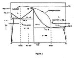
Figure 2 is a phase diagram illustrating homogenization of two components into an alloy. -
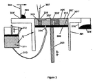
Figure 3 is sectional view of alternative equipment suitable for carrying out the process of the invention. -
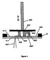
Figure 4 is sectional view of still further alternative equipment suitable for carrying out the process of the invention. -
Figure 5 is a phase diagram illustrating the phase relationship of gallium and aluminum. - The term "homogenized" or "homogenization", for the purposes of this disclosure, will refer to the formation of an alloy between the substances which are homogenized. This requires sufficient molecular or elemental mixing between the components to result in properties, either physical or chemical or both, which are different from the properties of the individual components in intimate contact in the form of a dispersion. The difference in properties of the alloy is preferably sufficient in itself to permit separation of the alloyed components from non-alloyed, surrounding regions of the dispersed components following imagewise exposure. In a particularly preferred embodiment, the alloyed (homogenized) material has a different melting point than the dispersion of components A and B, and thus, the alloyed three-dimensional article can be separated from the surrounding dispersion based on the difference in melting point.
- Components which can be alloyed from a dispersion of components in the manner described, and which may be used as component A and component B in the practice of the invention, include polymers, metals, and ceramics. In some instances, non-metal elements may be alloyed with metals. Preferred alloys formed by homogenization include polymer/polymer alloys, metal/metal alloys, ceramic/ceramic alloys, polymer/metal alloys, and metal/ceramic alloys. Choice of the particular material combination to be used depends on the nature and intended use of the three-dimensional part or object being produced. From within these classes of materials, the components A and B should be selected so as to be: capable of alloying under the exposure of imagewise radiation within a practical range of intensity; the alloy must have physical and/or chemical properties distinct from the properties of an intimate dispersion of A in B or B in A; and the alloy of A and B should preferably be separable from unalloyed dispersion of A and B based on the difference in physical and/or chemical properties.
- The components may consist of polymers, which can be dispersed together and alloyed by the application of radiation. In a preferred embodiment, a first particulate polymer (A) is dispersed in a second, liquid polymer (B) to form an intimate dispersion. Application of imaging radiation causes the particulate polymer to assume a different form in the liquid polymer, which changes the conformation of the particulate to allow for more intimate interaction between the first polymer and the liquid polymer. This interaction of the two polymers forms a polymer alloy having properties (for example melting point) different from polymer A, polymer B, and the intimate dispersion of polymer A in polymer B. The homogenization to form an alloy between polymers is a non-polymerization interaction, and polymerization techniques (free radical, condensation, and like mechanisms between monomers and/or oligomers and optionally initiators) are excluded from the definition of "homogenization" as used herein. The interaction between polymers upon imagewise exposure to radiation is primarily noncovalent, involving hydrogen bonding, n-pi complexing, pi-pi complexing, or dipole interactions, although incidental grafting, cross-linking or the like which may occur between the polymers is not excluded.
- The components may consist of metals or ceramics which, when contacted with appropriate imaging radiation of appropriate intensity, form a metal or ceramic alloy having properties distinguishable from the properties of the components. For example, powdered bismuth and powdered magnesium can be combined, in the ratios of about 30 atomic percent bismuth to about 70 atomic percent magnesium, as an intimate powder dispersion. Although the components are in intimate contact, the bismuth powder and the magnesium powder retain their characteristic, individual properties. Even if the bismuth powder (melting point 268.5 °C) is melted sufficiently to wet the magnesium powder (melting point 650 °C) and thus increase the intimate contact between the components, each component in the dispersion still retains its essential and unique properties. However, if the magnesium powder is also melted and mixing results between the melted bismuth and magnesium, then either the intermetallic compound Mg3Bi2 (melting point 823°C) is formed, or upon more intense radiation, a higher melting point alloy is formed. It will thus be understood that homogenization, in the case of metals and ceramics, is different from conventional sintering techniques, wherein powders are heated to essentially fuse or bond the particulates at their outermost points of contact into a solid mass. This also distinguishes the homogenization process of the invention from selective laser sintering (SLS) techniques. Thus, it will be understood that "homogenization" for purposes of the invention requires intimate mixing of at least two components with resultant formation of an alloy between the components, which cannot be achieved using conventional sintering techniques. Moreover, in the case of sintering, the sintered object cannot be separated from a surrounding powder bed based on melting temperature, whereas convenience of separation is an advantage associated with certain embodiments of the present invention.
- Techniques similar to sintering are "brazing", welding and soldering. Brazing is a metal joining process wherein a nonferrous filler metal wets a base metal when molten in a manner similar to a solder and its base metal. There is a slight diffusion of the filler metal into the hot, solid base metal, or a surface alloying of the base and filler metals. A surface bond is formed between materials that does not cause changes in physical properties in the individual components except at the surface. Brazing, welding and soldering are also different from homogenization as described herein.
- It should be noted that homogenization does not require complete mixing. It is recognized, for example, that solidified alloys may contain crystals or phases of varying composition. In the context of the present invention, homogenization progresses to the extent that the homogenized regions forming the three-dimensional integral object have different properties, and normally can be separated from the non-homogenized surrounding regions based on those different properties.
- Suitable polymer materials for components A and B are disclosed generally in the following disclosures, which are incorporated herein by reference. Polymer alloys are disclosed in Batelle, "Report on Major Developments in Polymer Blends", Vols. 1-3, Columbus Division, Columbus, Ohio, (1986); and Barlow et al., Polymer Blends and Alloys, A Review of Selected Considerations, Polymer Engineering and Science, 21: 985(1981). Polymers used as component A or B may comprise pure polymer or may comprise polymers and related monomers and solvents.
In the polymer alloys (sometimes called polymer blends) the repeating functional units of one polymer interact with the repeating units of the other polymer(s) in a manner which renders the polymers miscible and makes the alloy thermodynamically stable upon imaging. As noted, such interactions are primarily noncovalent. The polymer alloys have different properties than the individual polymers or the polymers in dispersion, such properties including, for example, melting temperature, glass transition temperature, heat distortion temperature, and the like. Exemplary of polymer pairs suitable for components A and B of the invention are the following: polycaprolactone/poly(vinylchloride); polycaprolactone/Saran; polycaprolactone/bisphenol A polycarbonate; poly(vinyl methyl ether)/phenoxy; poly(ethylene oxide)/phenoxy; poly(ethylene oxide)/poly (acrylic acid); BPA polycarbonate/PHFA; polystyrene/polyphenylene oxide. - Metallic alloys are disclosed in, for example, Hansen, "Constitution of Binary Alloys", McGraw-Hill (1958); and A.S.M. Metals Reference Book, ASM International, Materials Park, Ohio (1993).
- Preferred ceramic/ceramic and ceramic/metal alloys are disclosed in "Phase Diagrams for Ceramicists", Vols. 1-8, The American Ceramic Society, Columbus, Ohio.
- Material pairs selected from within the materials disclosed in these references should be selected to achieve the criteria described above, primarily, alloy formation upon imagewise exposure to radiation.
- In a currently preferred embodiment of the invention, the components A and B exhibit properties in accordance with the phase diagram shown in
Figure 2. Figure 2 illustrates certain preferred principles to be considered, but should not be understood as limiting the possible phase relationships between components.Figure 2 shows, by means of a phase diagram the characteristics of a binary alloy of component A and component B having properties particularly contemplated for use in this invention. The X-axis starts with 100% of component A at the left and increasing amounts of component B moving toward the right. The Y-axis shows increasing temperatures. Component A tends to crystallize in crystalline structure α especially when in pure form. Component B tends to crystallize in crystalline structure β especially when in pure form. Components A and B preferably form an intercomponent compound AB at a certain relative percentage of component A and component B. Intercomponent compounds AB may have different component ratios than the stochiometric ratios which are required with other chemical reactions and with other chemical compounds. In addition, the type of bonding for chemical compounds may be different from that of alloy crystals and intercomponent compounds. The intercomponent compound AB provides a thermodynamic barrier which allows a distinct separation based on melting point. Intercomponent compounds AB are not necessarily line compounds, as shown, but may exist over a broader composition range of component A and component B. The melting point of component A is shown as MpA, the melting point of component B is shown as MpB, and the melting point of intercomponent compound AB is shown as MpAB. Above the various melting points is a region shown as L (liquid) and may be interpreted as a liquid mixture of components A and B. At lower percentages of component B and at temperatures below a eutectic isotherm line EuA, components A and B form a crystalline alloy comprised of α and intercomponent crystal AB. At higher percentages of component B and at temperatures below a eutectic isotherm line EuB, components A and B form a crystalline alloy comprised of β and intercomponent crystal AB. At temperatures above these eutectic isothermal lines EuA and EuB or above the α and β solidus curves, the mixture of components forms either a liquid L or a dispersion of one of the solid crystalline components α, β, or AB and liquid L. In other words, above these eutectic isothermal lines Eu A and Eu B or solidus curves, melting begins to occur. As seen inFigure 2 , the melting point of intercomponent compound AB, MpAB is the highest, followed by MpA, then EuA, then MpB, with the melting point of EuB being the lowest. - Phase diagrams such as
Figure 2 represent the state of component mixtures under equilibrium conditions where the components are mixed on a molecular or atomic level in the liquid state and are allowed to cool slowly such that the crystalline structure and composition occur as depicted (or where solid state diffusion exists and sufficient time is allowed such that an equilibrium is reached). If cooling is fast, different crystalline structures or compositions may exist. If solid powders of component A are introduced into a liquid bath of component B at a temperature above MpB but below MpA, a dispersion of powdered A in liquid B may result rather than a molecular or atomic mix of components A and B. This is more likely when the solubility of liquid component B is low in solid component A since, under such temperature conditions, homogenization may not occur or may occur slowly. Homogenization may also be somewhat inhibited if liquid component B does not easily wet solid component A. However, it is preferred that good wetting exist between components A and B. - With reference to
Figure 5 , as another example, aluminum and gallium form a eutectic EuB with a melting point of roughly 26.6°C for weight percent compositions of approximately 20 to 92.2% gallium. However, there is a remarkable increase in melting point along the (Al)crystalline solidus line for alloys comprising less than approximately 20 weight % gallium. In this example, if a dispersion comprising an alloy AlBl of slightly more than 20 weight % gallium with aluminum as the liquid phase component B and a powdered component A of aluminum is provided and coated into a layer, then a homogenized alloy region A2B2 of the dispersion would have a significantly higher melting point. For example, consider the following dispersion AlBl + (S)A: - 50 parts of component B (Alloy AlBl containing
- 30% gallium and 70% aluminum)
- 50 parts of solid component A (powdered aluminum)
- The dispersion AlBl + (S)A would begin to form a liquid phase if heated to above 26.2°C. The amount of liquid can be calculated based upon tie-line calculations well known in the art. Above this temperature, the dispersion(L)AlBl + (S)A could be coated into a layer. Next, the layer could be imagewise homogenized forming an alloy region A2B2 having a composition of 85% aluminum and 15% gallium. This region A2B2 (assuming complete homogenization of the aluminum and gallium) would have a melting point of over 300°C. The difference between the homogenized alloy A2B2 melting point and the melting point EuB of the dispersion (L)AlBl + (S)A would allow separation of the homogenized region A2B2 from surrounding dispersion(L)AlBl + (S)A.
- In forming objects using alloys of aluminum and gallium, those skilled in the art would recognize that the liquids curve extends up to 99.2% by weight of gallium. This reduces the amount of liquid formed (based upon tie-line estimates) in the liquid component (L)AlBl + (S)A so that higher temperatures T1 should be used during coating. Alternatively, coating pressures, such as the use of a heated roller, could be used to aid the formation of the dispersion (L)AlBl + (S)A into a layer.
- Apparatus for carrying out imagewise formation of three dimensional parts are known in the art, and are described, for example, in
U.S. Pat. No. 5,354,414 ;5,474,719 ;4,575,330 ;4,938,816 ; and5,014,207 . Preferred apparatus is described below in connection with drawingFigure 1 . - The system illustrated in
Figure 1 utilizes focused radiation adapted to be scanned imagewise by means of, for example, an X-Y mirror scanning apparatus. As shown inFigure 1 , acylinder 101 and coating platform surface 101' are positioned such that the platform surface 101' is generally normal to and in the focal region ofbeam 107. Within thecylinder 101 ispiston 102, which is adapted to move up and down relative to the platform surface 101'. Thepiston 102 is driven by amotorized screw drive 103. Adoctor blade 104 is adapted such that the doctor blade edge 104' is slidably in close proximity with the platform surface 101' and traverses the platform surface 101' and the piston surface 102' or above the piston surface 102', should thepiston 102 be lower than the platform surface 101'. Thedoctor blade 104 is driven by a motor drive/linear bearing mechanism not shown. A portion of dispersion of components A andB 105 is placed on theplatform surface 101 in advance of the motion of thedoctor blade 104 such that the blade edge 104' can spread thedispersion 105 across the platform surface 101' and across the piston surface 102'.Enough dispersion 105 is placed forward of the motion of thedoctor blade 104 to fill in a cavity made within thecylinder 101 between the platform surface 101' and the surface of the piston 102'. Initially thepiston 102 is positioned within thecylinder 101 such that the piston surface 102' is approximately one layer thickness below the surface of the platform 101'.Doctor blade 104 traverses across the platform surface 101' and spreads thedispersion 105 into the cavity made by thepiston 102 and thecylinder 101. Thecoated dispersion 106 within the cavity is exposed imagewise bybeam 107 inpart regions 108 and 108', the part regions being shown as having different shapes. In the exposedregions 108 and 108', thecoated dispersion 106 is heated by thefocused beam 107 such that the components A and B are homogenized andform alloy regions 108 and 108' which are hardened and can be separated from the surroundingliquid dispersion 106. Normally, the first formedregions 108 and 108' are adhered to the piston surface 102'. Next,piston 102 is moved down another one layer thickness forming a cavity between the dispersion surface 106', thepart surface 108 and 108', and the platform surface 101'.More dispersion 105 is placed in advance of the motion of thedoctor blade 104. Thedispersion 105 is spread into the cavity forming a new coated dispersion surface 106'. Then this dispersion surface 106' is exposed imagewise withbeam 107 forming new homogenized part surfaces 108 and 108'. Adequate exposure is provided bybeam 107 to ensure adhesion between the new part surfaces 108 and 108' and the previously homogenized part surfaces exposed after the first coating step. This adhesion is assured by providing enough energy throughbeam 107 to make thenew layers 108 and 108' thicker than thecoated layer 106. The adhered layers formintegral parts 109 and 109'. By repeating the process of creating a cavity, forming a new coated surface 106' and exposing the surface 106' inimage regions 108 and 108' with thebeam 107, multilayer homogenizedintegral parts 109 and 109' are formed. Although in general heat Q is provided simply by ambient air surrounding the apparatus ofFigure 1 , it may be necessary in some cases to pre-heat the surface of piston 102' prior to coating the first layer to assure adhesion between thefirst image region 108 and 108' and the piston surface 102'. This preheating Q can be accomplished with a hot air gun, or can be applied to any portion of the apparatus ofFigure 1 by any heating method, for example resistance wires, ambient air, orexposure beam 107. - The
parts 109 and 109' as shown are cantilevered sections and other unsupported sections as depicted inFigure 1 . The parts formed may be solid parts, or may be partially hollow. There are no size limitations on the parts which can be formed other than the capacity of the equipment and the fineness of thedispersion 106. - A further preferred means of carrying out the invention is described with reference to both
Figure 1 andFigure 2 . Adispersion 105 is supplied beforedoctor blade 104. Thedispersion 105 comprises a dispersion of liquid alloy A1B1 which has a composition coincident with eutectic isothermal EuB at the eutectic point and also comprises a solid component of pure A (seeFigure 2 ). In this example, the composition of thedispersion 105 is such that, if completely homogenized bybeam 107, thedispersion 105 would form analloy region 108 having a composition A2B2, which is shown inFigure 2 as a composition coincident with the eutectic point on the eutectic isothermal line EuA. Heat Q is supplied to the apparatus such that the temperature of the apparatus inFigure 1 is at T1 inFigure 2 . Thedispersion 105 is also at temperature T1 as shown inFigure 2 during spreading bydoctor blade 104 over the platform surface 101' and piston surface 102', or over the previouscoated dispersion 106 orhomogenized objects 109 and 109'. Thereforedispersion 105 has a liquid phase component (L)A1B1 and a solid phase component (S)A at temperature T1 as shown inFigure 2 . Prior to coating thedispersion 105, thepiston 102 is moved down in the cylinder 101 a distance such that a cavity exists above the piston surface 102' and below the platform surface 101'. The distance is the depth of one layer of theobject 109 and 109' to be formed. After coating ofdispersion 105 withdoctor blade 104, a layer ofcoated dispersion 106 fills this cavity. Afocused beam 107 is then scanned imagewise over the surface of coated dispersion 106' such thathomogenized regions 108 and 108' are formed. Thefocused beam 107 supplies enough heat to raise the temperature of thedispersion 106 from temperature T1 to temperature T2, as shown onFigure 2 . At temperature T2 [or below if the melting point of component A is depressed in (L)A1B1] the solid component (S)A, of the composition (L)A1B1 + (S)A, melts forming the composition (L)A1B1 + (L)A. With all the components in the liquid state at temperature T2, rapid homogenization occurs creating a new composition (L)A2B2 at temperature T2. Upon cooling to below temperature EuA this composition (L) A2B2 solidifies to (S)A2B2 forming anobject layer 108 and 108' surrounded bydispersion 106. In this example, thelayer 108 and 108' would eventually cool to temperature T1. - Next the
piston 102 is moved down the distance of one layer creating a cavity between the surface of dispersion 106' or thelayer 108 and 108' and the platform surface 101'.New dispersion 105 is spread into this cavity creating an additional layer ofcoated dispersion 106. This layer ofdispersion 106 is scanned imagewise withbeam 107 such that all the components in thedispersion 106 are heated to temperature T2 causing melting and homogenization in theimage regions 108 and 108'. Thenew image regions 108 and 108' are allowed to cool until new solid homogenized alloy regions (S)A2B2 108 and 108' are formed. Theseregions 108 and 108' preferably adhere to the previous alloy (S)A2B2 regions forming part of theintegral objects 109 and 109'. Thepiston 102 is then lowered and all the coating and imagewise homogenization steps are repeated until completeintegral objects 109 and 109' have been formed. - Upon completion of fabrication of
integral objects 109 and 109', thepiston 102 is raised.Dispersion 106, maintained at temperature T1, is allowed to flow away thereby separating thedispersion 106 from theintegral objects - As an alternative to the above, only the
doctor blade 104 and thedispersion 105 are heated to a temperature T1 while the remainder of the equipment shown inFigure 1 is maintained at a temperature less than EuB. All the fabrication steps would be the same as described above, with the exception of the last step. In the last step, thepiston 102 would be raised. The solidified block consisting of solidifiedcoated dispersion 106 andintegral objects 109 and 109' would be removed from the piston surface 102'. The solidified block would then be placed in an oven at temperature T1 where thedispersion 106 would be melted away from theintegral objects 109 and 109'. As a further alternative, thepiston 102 could be placed in the oven with the solidified block attached. The dispersion would then melt and flow away leaving theintegral objects 109 and 109' which could be removed from thepiston 102. - For some components A and B there may be a significant difference in density making the
dispersion 106 unstable such that the liquid phase (L)A1B1 and the solid particles (S)A separate by gravity into separate layers. Such separation can be handled in different ways. One way would be to maintain thecoated dispersion 106 at a temperature below EuB or solid so separation cannot occur or even if separation occurred it would happen layer by layer. Thefocused beam 107 could still be used to melt both the low melting component and the solid particle component to perform imagewise homogenization. Another way would be to use solid particles (S)A which are a higher melting alloy, an alloy of A and B (e.g. A1' B1' as shown inFigure 2 ) than the liquid phase (L)A1B1 at temperature T1. The higher melting alloy would have a closer initial density with regard to the liquid phase density. - However, it is most preferred that the lower melting component(L)A1B1 be comprised of a significant amount of component A. This has two advantages, there is less of a density difference and less of component A need be present in order to enrich the alloy to a higher melting composition. Such a lower melting component (L)A1B1 would have a composition comprising component B in a % slightly more than intercomponent compound AB as shown in
Figure 2 . - Another method to carry out the process of the instant invention is shown in
Figure 3 . The apparatus ofFigure 3 is very similar to that ofFigure 1 . However, the operation is somewhat different. In this embodiment a solidpowdered component 306 has a lower density than that of aliquid phase 310.Piston 302 is positioned withincylinder 301 such that a cavity is formed between piston surface 302' and coating platform surface 301'. The thickness of the cavity is less than the thickness of one layer. Solid powdered component 305 [(S)A inFigure 2 ] is spread bydoctor blade 304 with tip 304' slidably in contact with coating platform surface 301' such that the cavity is filled with spread solid powder component 306 [(S)A inFigure 2 ]. Next thepiston 302 is translated down bydrive mechanism 303 the remaining thickness of the layer (i.e. the distance between the piston surface 302' and the platform surface 301' is one layer thickness).Pumping device 312 pumps liquid phase component 311 [(L)A1B1 inFigure 2 ] throughconnector hose 313 andplatform nozzle 314 into the cavity until thesolid powder component 306 is substantially even with the top of the platform surface 301'. Heat Q is supplied to the apparatus and thepump 312 to maintain a temperature of T1 (as inFigure 2 ). Since thesolid powder component 306 has a lower density than theliquid phase component 310, thepowder 306 floats at the surface but is preferably wetted by theliquid phase component 310.Focused beam 307 is scanned imagewise over the surface of thesolid powder component 306 causing it to melt (the temperature is raised to T2 as inFigure 2 ). The meltedpowder component 306 then rapidly homogenizes with theliquid phase component 310 in the image region and forms analloy region 308 and 308' [(L)A2B2 inFigure 2 ]. Thisalloy region 308 and 308' is allowed to cool to below temperature EuA inFigure 2 and becomes solidifiedalloy region 308 and 308'.Pump mechanism 312 pumpsliquid phase composition 311 into the cavity such that any remainingsolid powder component 306 is raised above coating platform surface 301'.Doctor blade 304 is translated across the coating platform surface 301' and the solidpowdered component 306 and some of theliquid phase component 310 are combined into adispersion 315 which is pushed intocontainer 316.Piston 302 is moved down less than the thickness of one layer. Newsolid powder component 305 is placed in front ofdoctor blade 304 where it is spread into the cavity made by the solidifiedalloy regions 308 and 308' and the surface ofliquid phase component 310. Next thepiston 302 is translated down the remaining distance of one layer.Pump mechanism 312 pumps moreliquid phase component 311 into the cavity adding toliquid phase component 310 in the cavity. Enoughliquid phase component 310 is pumped until the surface of thesolid powder component 306 is substantially level with the surface of the coating platform 301'.Focused beam 307 is then scanned imagewise forming newhomogenized alloy regions 308 and 308' which adhere to the previously formedimage regions 308 and 308', where they overlap, thereby formingintegral objects 309 and 309'. The steps of scraping off remainingdispersion 315, creating a cavity for coatingnew powder 306, creating a cavity for pumping in newliquid phase component 310, imagewise exposing withbeam 307 to homogenizenew regions 308 and 308' which adhere tointegral object 309 and 309' are repeated until theintegral objects 309 and 309' are completed. Finally, theintegral objects 309 and 309' are separated from thepowder 306 due to lack of inter-particle bonding, and from theliquid phase component 310 due to the difference in melting temperature. - As a further variation of the embodiment of
Figure 3 , it is envisioned that thesolid phase component 306 could be supplied in the form of a thin sheet which is melted imagewise byfocused beam 307 to formhomogenized alloy regions 308 and 308'. Anew sheet 306 could be supplied for each layer. Such a method could be used independent of the density of the material components. - Still another embodiment involves the addition of a material component A in either solid or liquid form, in an imagewise fashion, to the surface of a liquid phase component (L)A1B1 contained in a vat or a piston/cylinder cavity. In the regions where the material component A is placed, homogenization would result forming an alloy (S)A2B2 having a higher melting temperature than the temperature of surrounding liquid phase component (L)A1B1. The homogenized regions would harden into layers which would be built into integral objects. The integral objects could then be separated from the surrounding liquid phase component (L)A1B1 since the objects would be solid at that temperature. The imagewise addition of material component could be accomplished using ink jet technology or powder jet technology.
- In the practice of the invention the preferred property change for separation of imaged objects from non-imaged dispersion is a melting point change. The melting point change, assuming it is sufficiently large, allows a separation of the homogenized region from the unhomogenized region (unexposed to radiation) though the application of heat which causes the lower melting point region to melt away from the higher melting point region.
- The layer-by-layer process as described herein allows the production of objects with property changes that exist deep within the object and with property changes of specific shape within the object. Returning to the example of the dispersion of bismuth and magnesium, it is possible to produce shaped object regions, which are homogenized such that the intermetallic compound Mg3Bi2 (melting point 823°C) and dispersed Mg is the primary alloy, within an object which has greater homogenization such that an alloy having a temperature of 551°C is formed. For example, the homogenization time or temperature could be lower for the intermetallic compound region, such that some magnesium powder is surrounded by the intermetallic compound.
- In the practice of liquid phase sintering it is known that approximately 35% volume liquid is preferred, since this volume percent allows optimum rearrangement of the solid particles in the dispersion and therefore the greatest amount of densification. However, greater or lesser amounts of liquid may be present depending on the wetting characteristics of the particles with the liquid and the solubility characteristics of the components. In addition, since the process of the present invention involves a layer-by-layer processing of the dispersion or a surface liquid phase sintering process, rather than, for example, an impregnation of liquid into a compacted powder as in a bulk liquid phase sintering process, problems related to pore growth and such can be easily relieved through the surface during processing. Thus, the optimum liquid to solid ratios for surface liquid phase sintering are much broader than those ratios recommended for bulk liquid phase sintering. It is also important to note that a liquid phase need not be present just prior to the homogenization step when practicing the instant invention. Indeed it may be preferable to have the liquid phase present only during the coating steps, during the homogenization steps, and during the object separation steps when components A and B have a degree of solubility such that over a short period of time, premature homogenization occurs, since homogenization is usually greatly enhanced when at least one component is in the liquid state. Another method to prevent premature homogenization would be to use coated particles. The coating could be such that homogenization is only possible at elevated temperatures. An example coating would be an oxidized coated solid particle A. This oxide coating would be lost at the higher homogenization temperatures and could be reduced in an atmosphere of, for example, hydrogen. Or, the oxide coating could be incorporated as a third component into the homogenized alloy article.
- Furthermore, the liquid phase need not be comprised of a pure component B or a pure component A. The liquid phase may be comprised of, for example, an alloy of component A and component B at a eutectic point such that upon heating above the eutectic isothermal line EuB temperature the liquid phase does not have crystalline components AB or β. Such a condition ensures a greater amount of liquid to solid particle ratio and also reduces the amount of homogenization required to change the composition to a higher melting alloy.
- There are advantages when the solid particles are comprised of an alloy of components A and B at the eutectic point on the isothermal eutectic line EuA. With such an eutectic point alloy, the temperatures needed during the homogenization step or the amount of heat given during imagewise exposure can be lower since the alloy transitions directly to a liquid without containing some crystalline content of α or AB. However, use of an eutectic point alloy as the solid particle may require that more of the solid component be provided in the dispersion prior to homogenization since a certain amount of component A must be present in the imagewise homogenized region for a higher melting point alloy to be formed. A similar type situation occur, when starting with a lower melting alloy having a composition where the EuA line meets the α crystalline solidus curve and attempting to enrich this alloy with component A in order to form a higher melting alloy along the α solidus curve. Significant amounts of component A need to be homogenized into such an alloy. Such situations are less preferred since homogenization becomes more difficult.
- For many material components and alloys, the atmosphere surrounding the process is critical. For example, some components may easily oxidize and require the use of vacuum conditions, inert gases, or reducing atmospheres in order to form the integral objects. Atmosphere can be controlled in the process or used in the alloy reaction. For example, oxygen can be used to form a ceramic alloy on the surface of a layer of liquid phase metal. Such a ceramic alloy or cermet (metal ceramic) typically has a much higher melting point than the surrounding pool of metal, allowing easy separation of an integral object. The metal component in this case could be supplied in sheet form and the oxygen could be supplied with, for example, an acetylene torch (with excess oxygen for some materials which are easily reduced with heat or with insufficient oxygen for materials which oxidize in the presence of carbon oxides) which is translated imagewise over the surface of each sheet stacked one on another. The heat from the torch would create a localized liquid phase component which would react with oxygen forming a higher melting alloy region. A new sheet would then be applied to the previous sheet and higher melting alloy region. The torch would then be translated imagewise over the surface of the new sheet forming a higher melting alloy region which would preferentially adhere to the previous alloy regions forming part of an integral object. This process would continue until all the layers of the integral object are formed. Then the sheets and the integral object would be placed in an oven (with a vacuum, inert or reducing atmosphere) such that the non-oxidized portions of the sheets are melted and allowed to flow away from the higher melting alloy integral object.
- It is also possible to form regions of lower melting point by enriching a higher melting point layer with a component which, when homogenized with the higher melting point component, forms a lower melting point alloy. For example, a sheet of a higher melting point component A could be supplied. A second component B could be deposited imagewise on the surface of the sheet. The imagewise deposition of the second component could be a perimeter of the integral object to be formed or a region of greater area. The second component would be chosen such that, when the higher melting component and the second component are homogenized, a lower melting point alloy results. The second component would also be chosen such that the melting point of the sheet component would be depressed when in contact with the melted second component. The stacking of the sheets and the imagewise deposition of the second component would continue until all layers of the potential object have been applied. The stacked sheets (with the imagewise deposited second component) would then be placed in an oven at a temperature (above the depressed melting point temperature of the sheet but below the melting point of the sheet component) where the second component would melt and cause the stacked sheets to melt imagewise forming imagewise regions of relatively low melting alloy which would be drained away from the non-imaged stacked sheet regions. The non-imaged stacked sheet regions would then be heated to a temperature such the sheet layers sinter together and create an integral object. In a similar embodiment, the imagewise deposition step could be accompanied by an imagewise heat step such that a lower melting alloy results at each layer. If the temperature of the stacked sheets are above the melting point of the alloy, the alloy could be drained or removed by other means, such as by vacuum, at each layer.
- Separation of the dispersion from the homogenized object can also be enhanced by using a suitable solvent. For example, the melting point of the dispersion could be lowered after the homogenized object has been formed by homogenizing the dispersion with additional low melting component or by the addition of another component capable of lowering the dispersion melting point.
- Some homogenized regions and integral objects may be significantly soluble in the liquid phase component or even a solid phase component over a period of time. This condition would cause a loss of resolution in the object during manufacture since the object might dissolve in the liquid phase or the solid dispersion. In general, it is preferred that components are chosen such that the homogenized object is not significantly soluble in the dispersion of A and B. Problems in this regard can be avoided if the annealing temperature of the homogenized object is above the temperature required for separation of the homogenized object from the dispersion. For example, homogenized objects could be formed using nickel and copper as the components. Copper has a melting point of 1085°C and nickel has a melting point of 1455°C. The melting point of homogenized alloys of copper and nickel would increase roughly linearly as a function of increasing nickel. However, typical annealing temperatures for copper-nickel alloys are below 870°C indicating substantial solid solubility of copper with nickel. Therefore it is unlikely that a dispersion could be maintained or that the dispersion could be separated from the homogenized object, since the solubility of these components and alloys is high and the homogenized object would begin to lose resolution below the melting temperature of the low melting copper component.
-
Figure 4 illustrates a process embodiment designed to minimize the length of time that the integral object is in contact with a liquid phase component. In the embodiment ofFigure 4 aplatform 402, having a surface 402', is translated using amotorized drive 403 and positioned above and coplanar to aplate 417. Theplate 417 may be made of, for example, fused silica glass such that focusedbeam 407 can be transmitted through it, or for example a high melting but conductive material, such as tungsten, which would absorb the energy fromfocused beam 407 and conduct the energy in the form of heat through a plate surface 417' todispersion 405. Initially,platform 402 would be positioned in the liquid pool ofdispersion 405 such that the platform surface 402' would be one layer thickness from the surface of plate 417'. Referring toFigure 2 , the temperature of dispersion 405 (and preferably substantial portions of the apparatus ofFigure 4 as provided by heat Q) is T1 and the composition is (L)A1B1 + (S)A. Referring back toFigure 4 , focusedbeam 407 is then scanned imagewise onregions 408 of thedispersion 405 in this layer raising the temperature [to T2 ofFigure 2 ] of theseregions 408 and causing homogenization [and a new composition (L)A2B2 ofFigure 2 ] such that the melting point of theregions 408 is raised [to above the solidus lines of either α or EuA inFigure 2 ] and upon cooling below the solidus, form solid regions 408 [having a composition (S)A2B2 inFigure 2 ]. Preferably, thesolid regions 408 adhere to platform surface 402' but do not substantially adhere to plate surface 417'. Next,platform 402 is raised at least the distance of one layer such thatdispersion 405 forms a layer betweensolid region 408 and the surface of the plate 417'.Focused beam 407 is then scanned imagewise such that anew region 408 is homogenized and upon cooling preferentially adheres to thehomogenized region 408 of the previous layer thereby forming a part ofintegral objects 409 and 409'. The steps of positioning theplatform 402 such that a new layer ofdispersion 405 is formed between homogenizedsolid region 408 and exposing withfocused beam 407 imagewise such that newhomogenized regions 408 are adhered tointegral object 409 and 409' is continued until theobjects 409 and 409' are complete. The level ofdispersion 405 can be such thatadequate dispersion 405 is supplied to form theobject 409 and 409' but not enough to keep theobject 409 and 409' submerged for long periods of time. In order to give further assurance of limited contact, when an object 409' (shown in cross section) has an enclosedvolume 409" (a hollow region surrounded by part surfaces) such as shown with object 409', it may be necessary to raise theplatform 402 to a distance greater than one layer in order to allow theenclosed volume 409" to drain ofdispersion 405. Then theplatform 402 can be lowered to form the new layer thickness. - Although separation of an integral object from a lower melting point region has been stressed, there are useful modes of carrying out the instant invention that do not require object separation. For example, a region of an object formed in a layer-by-layer process as described herein may be enriched, with greater amounts of the same or another component, such that it has different magnetic properties than the remainder of the object. For example, a gear could be formed with a region of different magnetic susceptibility which when rotated past a magnetic sensor would create an electrical pulse like an encoder. As a further example, a turbine could be formed with an internal region of a lower melting alloy or density which would provide an automatic balancing mechanism for the turbine at its operating temperature. As another example, regions could be included in integral objects which have different hardness, ductility, electrical/thermal conductivity, elasticity, color, etc., than the remainder of the object.
- The foregoing disclosure will be illustrated by the following example, which is provided as illustration and not as limitation on the scope of the invention.
- The following dispersion was prepared by mixing: 300 grams of crystalline 400,000 MW polyethylene oxide, 120 mesh 700 grams of trimethylolpropane triacrylate 11 grams of fine graphite lubricant powder. The dispersion was mixed at room temperature to uniform consistency and moderate viscosity. Trimethylolpropane triacrylate is a liquid at room temperature and formed a liquid phase of the dispersion. Below approximately 43°C, the polyethylene oxide is essentially insoluble in the trimethylolpropane triacrylate. Above this temperature, sudden homogenization ensues with the homogenized region forming a rubbery solid having a higher melting point. The graphite was added to increase the surface absorption of the laser beam energy used (Argon Ion laser operating in the visible with all visible lines predominantly 488 and 514 nm). The graphite would not be necessary if laser wavelengths having greater surface absorbance were used or if other imagewise heating methods were employed.
- The surface of the dispersion was scanned with the laser beam in a series of parallel lines spaced approximately 0.002 inches apart. The diameter of the beam spot was approximately 167
µm 1/e2 and the power was 2.89 watts. The photospeed of the dispersion was obtained by pouring a portion of the dispersion in a petri-dish and exposing the surface of the dispersion in one inch square regions. Shortly after exposure, and after the region was allowed to cool, the exposed surface was removed. The bottom surface of the layer was scraped off with a spatula and the layer thickness was then measured with calipers. By scanning the surface of the dispersion at various scan speeds the photospeed of the dispersion was found to be Ec 2644 mJ/cm2 and Dp 21.7 mils. Scanning of the focused beam was achieved utilizing an X-Y mirror set which deflected the focus of the beam across the surface of the dispersion in an imagewise manner utilizing the scanning technology disclosed inUS patent 5,014,207 . Although it is preferred to modulate the beam at the end of vectors and while drawing the vector lines, in order to provide uniform exposure, the beam was not modulated while carrying out the steps in Example I. - While approximately 7 parts of trimethylolpropane triacrylate to 3 parts of polyethylene oxide were used for making the object in Example 1, greater amounts of polyethylene oxide in a composition can be used to make objects which retain some crystallinity, and lower amounts of polyethylene oxide may be used to form objects which are more rubbery (more plasticized by the un-alloyed triacrylate). Furthermore, other acrylates or diluents and other solid polymers are useful in the practice of the instant invention so long as the diluent and the solid polymer form an alloy having a higher melting temperature than at least the melting point of the diluent allowing easy separation of the alloy object from the diluent dispersion.
- Other objects, made simply by heat homogenizing 2 parts trimethylolpropane triacrylate and 1 part polyethylene oxide, were essentially insoluble in trimethylolpropane triacrylate or isopropyl alcohol and therefore these materials are suitable cleaning solvents when separating the homogenized objects from the dispersion. However, water tended to swell and soften a homogenized object made from this dispersion.
- The
parts 109 and 109' had cantilevered sections and other unsupported sections as depicted inFigure 1 . The size of the parts were as large as 2 inches (50 mm) square and 0.64 inches (16.3 mm) high. However, there was no identifiable limitation of size other than that of the capacity of the equipment used and the fineness of thedispersion 106. Thedispersion 106 was capable of producing unsupported, cantilevered and bridging, regions inparts 109 and 109' as large as 0.4 inches (10 mm). Theparts 109 and 109' were cleaned in isopropyl alcohol - The parts produced in this example can be used in an investment casting process where the parts are used as a pattern and dipped in a ceramic slurry. The pattern with the ceramic slurry shell can then be fired, burning off the pattern and hardening the ceramic shell. In order to prevent the water in the slurry from swelling the pattern, the pattern could first be dipped in a free radical initiator bath, for example a peroxide, which would tend to cross-link the trimethylolpropane triacrylate at the surface of the part. Alternatively, the pattern could be dipped in a free-radical photointiator liquid such as Irgacure (1173, 2-Hydroxy-2-methyl-1-phenyl-propan-1-one; Ciba Corporation, Hawthorne NY), or any liquefied free-radical photointiator, and then exposed to UV light in order to cross-link the outer portions of the pattern. Alternatively the pattern could be coated with, for example, a wax or a paint. During the firing process of a shell and pattern for investment casting, it is a known problem that the pattern may have a greater thermal coefficient of expansion than that of the ceramic shell. Under such conditions, the pattern may expand to such a degree that it cracks the shell before the pattern burns-off during firing. In the case of the example dispersion, the trimethylolpropane triacrylate will polymerize during the firing step and therefore the pattern will shrink. In fact, homogenized objects, made from the dispersion, were exposed to hot air from a hot air gun. The objects heated in this manner did not melt but became very stiff and then eventually charred. Alternatively, incorporation of a free-radical photointiator which is also thermally degradable, or a thermally degradable free-radical initiator, such as for example a Vazo®(Cyclohexanecarbonitrile, 1,1'-azobis, available from DuPont, Wilmington, Delaware) in the formulation would further ensure shrinkage, due to acrylate free-radical polymerization of the pattern during firing. In such a case for investment casting patterns, it is preferred that the photoinitiator not form significant quantities of free-radicals due to exposure by
beam 107, such as would occur when a dispersion containing a UV photoinitiator is exposed by visible or infra-red light, or that the temperature reached during the fabrication of theobject 109 not be high enough to cause the thermally degradable free-radical initiator to form significant quantities of free-radicals such that the acrylate is polymerized during object formation. For other object uses, some polymerization of the acrylate as well of homogenization of the dispersion may be advantageous and preferred. - The exposures necessary to produce a layer for the dispersion in Example I were somewhat higher than normally required. Light absorbers such as graphite are often not as efficient as certain thermal dyes which can be mixed on a molecular level, which have a greater yield for conversion of photon energy to phonon energy, and which may not have a large emittance. Although graphite and some other dyes have a fairly high and somewhat uniform absorption over the UV to near infrared spectrum, it should be appreciated that often other dyes have significantly greater absorption over a narrower wavelength region and are therefore optimally associated with lasers having an emission wavelength within the absorption wavelength of the dye. Examples of other thermal dyes are listed in
US 5,193,024 , with the squalarium dye SQS being preferred. Synthesis of SQS is disclosed in Kawamura (US Patent 4,283,475 ) and Gravesteijn (US Patent 4,508,811 ). SQS is best used with a diode laser emitting at a wavelength of approximately 830 nm. It should also be appreciated that in some cases the dispersion itself may have a significant absorption at the emission wavelength of some lasers. In such a case, it may not be necessary to add any other absorber in order to induce localized heat and subsequent homogenization of the dispersion in an imagewise manner. Furthermore, it should be appreciated that imagewise heat can be provided from other sources, such as for example an acetylene torch which, if fitted with a small tip, can produce a flame of resolution in the range of mils, for example "The Little Torch", manufactured by Smith Equipment, Waterton, South Dakota. Such a flame tip can be translated over the surface of the dispersion in an imagewise fashion by, for example, the adaptation of an X-Y pen plotter such that the flame tip replaces the pen. Or, if the dispersion and the homogenized region are electrically conductive and are adapted to form a ground plane, localized heat could be provided through the use of a translated carbon electrode, of opposite polarity to the ground plane, adapted to replace the pen in an X-Y pen plotter. The degree of homogenization may be controlled by, for example, homogenization temperature or homogenization time. The imagewise homogenization may also be aided through the use of localized ultrasonic energy, for example a modulated laser beam as taught inUS 4,330,699 by Farrow. - Other embodiments will be apparent to those skilled in the art from the foregoing description.
Claims (24)
- A process for producing a three-dimensional integral object 109,109', 309, 309', 409, 409' by imagewise radiation exposure of a dispersion 106, , 405, the dispersion 106, , 405 containing components A 305, 306 and B 310, 311, comprising the steps of:a) providing a dispersion 106, 405 of component A 305, 306 and component B 310, 311;b) forming the dispersion 106, 405 into a layer; characterized in that the process further comprises the steps of:steps a)-c) are repeated by applying each successive layer of dispersion 106, 405 of step b) onto the previous layer, such that each new homogenized region 108, 108', 308, 308', 408 becomes integral with the previous homogenized region 108, 108', 308, 308', 408 to form a homogenized, integral, three-dimensional object 109, 109', 309, 309', 409, 409', and wherein when the substances to be homogenized are polymers, the homogenization is accomplished by a non-polymerization interaction.c) homogenizing a region of the dispersion 106, 405 to a controlled degree of homogenization by the application of imagewise radiation exposure to heat said region to form a homogenized region 108, 108', 308, 308', 408 of an alloy of components A 305, 306 and B 310, 311; and
- The process as claimed in claim 1, wherein each homogenized region 108, 108', 308, 308', 408 has a different melting point than the dispersion 106, 405 of components A 305, 306 and B 310, 311.
- The process as claimed any of the previous claims, wherein components A 305, 306 and B 310, 311 are polymers, metals or ceramics.
- The process as claimed in any of the previous claims, wherein component A 305, 306 is a crystalline solid.
- The process as claimed in any of the previous claims, wherein component A 305, 306 and component B 310, 311 are metal powders.
- The process as claimed in any one of claims 1-4, wherein one of the components A 305, 306 and B 310, 311 is in an above solidus state in the dispersion 106, 405 of step (b).
- The process as claimed in claim 1, wherein component A 305, 306 is solid and component B 310, 311 is a liquid.
- The process as claimed in claim 7 wherein component A 306 and component B 310 differ in density, and the temperature of the dispersion 106, 405 is maintained so as to retard or prevent separation of the components 306, 310.
- The process as claimed in claim 7, wherein component A 305, 306 and component B 310, 311 differ in density and component A 305, 306 is a solid phase alloy of A and B dispersed in liquid component B 310, 311.
- The process as claimed in any one of claims 1-4 and 6-8, wherein component A 305, 306 has a melting point MpA, component B 310, 311 has a melting point MpB, and MpA is higher than MpB, and wherein homogenization forms an alloy 308,308' having a melting point which is different from MpB.
- The process as claimed in any one of claims 1-4 and 6-8, wherein the integral object 109, 109', 309, 309', 409, 409'is separated from the dispersion 106, 405 based on a difference in melting points.
- The process as claimed in any of the previous claims, wherein components A 305, 306 and B 310, 311 are polymers or a polymer and a monomer, each homogenized region 108, 108', 308, 308', 408 is formed by imagewise radiation exposure, and the homogenized object 109, 109', 309, 309', 409, 409' is a polymer alloy.
- The process as claimed in claim 12, wherein the polymer alloy of component A 305, 306/component B 310, 311 is polycaprolactone/poly(vinylchloride), polycaprolactone/Saran, polycaprolactone/bisphenol A polycarbonate, poly(vinyl methyl ether)/phenoxy, poly(ethylene oxide)/phenoxy, poly(ethyleneoxide)/poly(acrylic acid), BPA polycarbonate/PHFA, or polystyrene/polyphenylene oxide.
- The process as claimed by claim 1, wherein components A 305, 306 and B 310, 311 are metals, each homogenized region 108, 108', 308, 308', 408 is formed by imagewise radiation and the homogenized object 109, 109', 309, 309', 409, 409' is a metal alloy.
- The process as claimed in claim 14, wherein components A 305, 306 and B 310, 311 are bismuth and magnesium or aluminum and gallium.
- The process as claimed by claim 1, wherein the homogenized object 109, 109', 309, 309', 409, 409' is a metal or ceramic alloy.
- The process as claimed in claim 1, wherein one component of the region 108, 108', 308, 308', 408 is a polymer and the other component is a polymer or a metal.
- The process as claimed in any of the preceding claims, wherein the dispersion 106, 405 further comprises a thermal dye.
- The process as claimed in any of the preceding claims, wherein the process is carried out in an inert atmosphere, a reducing atmosphere, an oxidizing atmosphere, or under a vacuum.
- The process as claimed in any of the preceding claims, wherein said imagewise radiation exposure is applied as a series of lines defining an image.
- The process as claimed in any of the preceding claims, wherein said object 109, 109', 309, 309', 409, 409'has cantilevered or other unsupported sections.
- The process as claimed in any of the preceding claims wherein the imaging radiation exposure time or temperature of step c)is varied in a region of a layer.
- A process according to any one of claims 1-4, 6-8, 10-11 and 14-16, wherein the dispersion 106, 405 comprises a solidified alloy which contains crystals of varying composition.
- A process according to any one of claims 1-4, 6-8, 10-11 and, 14-16, wherein the dispersion 106, 405 comprises a solidified alloy which contains phases of varying composition.
Applications Claiming Priority (3)
| Application Number | Priority Date | Filing Date | Title |
|---|---|---|---|
| US08/846,271 US5980812A (en) | 1997-04-30 | 1997-04-30 | Solid imaging process using component homogenization |
| US846271 | 1997-04-30 | ||
| PCT/US1998/008490 WO1998048993A1 (en) | 1997-04-30 | 1998-04-28 | Solid imaging process using component homogenization |
Publications (3)
| Publication Number | Publication Date |
|---|---|
| EP1015213A1 EP1015213A1 (en) | 2000-07-05 |
| EP1015213A4 EP1015213A4 (en) | 2005-11-30 |
| EP1015213B1 true EP1015213B1 (en) | 2009-05-06 |
Family
ID=25297407
Family Applications (1)
| Application Number | Title | Priority Date | Filing Date |
|---|---|---|---|
| EP98919933A Expired - Lifetime EP1015213B1 (en) | 1997-04-30 | 1998-04-28 | Solid imaging process using component homogenization |
Country Status (9)
| Country | Link |
|---|---|
| US (2) | US5980812A (en) |
| EP (1) | EP1015213B1 (en) |
| JP (1) | JP4766723B2 (en) |
| AT (1) | ATE430648T1 (en) |
| AU (1) | AU7261298A (en) |
| CA (1) | CA2288153C (en) |
| DE (2) | DE98919933T1 (en) |
| ES (1) | ES2325696T3 (en) |
| WO (1) | WO1998048993A1 (en) |
Families Citing this family (39)
| Publication number | Priority date | Publication date | Assignee | Title |
|---|---|---|---|---|
| DE19846478C5 (en) * | 1998-10-09 | 2004-10-14 | Eos Gmbh Electro Optical Systems | Laser-sintering machine |
| US6547552B1 (en) * | 2000-02-08 | 2003-04-15 | Efrem V. Fudim | Fabrication of three-dimensional objects by irradiation of radiation-curable materials |
| WO2003000480A1 (en) * | 2001-06-22 | 2003-01-03 | The Regents Of The University Of Michigan | Methods of designing and fabricating molds |
| US6927018B2 (en) * | 2001-10-29 | 2005-08-09 | Hewlett-Packard Development Company, L.P. | Three dimensional printing using photo-activated building materials |
| US6865949B2 (en) * | 2003-01-31 | 2005-03-15 | Hewlett-Packard Development Company, L.P. | Transducer-based sensor system |
| US6913794B2 (en) * | 2002-01-14 | 2005-07-05 | Coherent, Inc. | Diode-laser curing of liquid epoxide encapsulants |
| US7306758B2 (en) | 2003-03-13 | 2007-12-11 | Hewlett-Packard Development Company, L.P. | Methods and systems for controlling printhead temperature in solid freeform fabrication |
| US7540996B2 (en) * | 2003-11-21 | 2009-06-02 | The Boeing Company | Laser sintered titanium alloy and direct metal fabrication method of making the same |
| KR100606457B1 (en) * | 2004-11-11 | 2006-11-23 | 한국기계연구원 | Three-dimensional printing prototyping system |
| DE102005022308B4 (en) * | 2005-05-13 | 2007-03-22 | Eos Gmbh Electro Optical Systems | Apparatus and method for manufacturing a three-dimensional object with a heated powder coating material build-up material |
| WO2007010598A1 (en) * | 2005-07-19 | 2007-01-25 | Homs Engineering Inc. | Process for producing stent and powder sintering apparatus |
| DE102005035987A1 (en) * | 2005-07-28 | 2007-02-01 | "Stiftung Caesar" (Center Of Advanced European Studies And Research) | Process for the preparation of three-dimensional shaped bodies |
| DE102006005500A1 (en) * | 2006-02-07 | 2007-08-09 | Degussa Gmbh | Use of polymer powder, prepared from a dispersion, in a molding process and molding, made from this polymer powder |
| DE102006023485A1 (en) * | 2006-05-18 | 2007-11-22 | Eos Gmbh Electro Optical Systems | Device and method for producing a three-dimensional object |
| DE102006049216A1 (en) * | 2006-10-18 | 2008-04-24 | Mtu Aero Engines Gmbh | High-pressure turbine rotor and method for producing a high-pressure turbine rotor |
| DE112008000475T5 (en) * | 2007-02-23 | 2010-07-08 | The Ex One Company | Replaceable manufacturing container for three-dimensional printer |
| KR100847550B1 (en) | 2007-04-27 | 2008-07-21 | 한국기계연구원 | Moulding roller device of three-dimensional printing prototyping system |
| EP2279499B1 (en) * | 2008-04-14 | 2016-11-23 | Rolls-Royce Corporation | Method for producing ceramic stereolithography parts |
| DE102008056336A1 (en) * | 2008-11-07 | 2010-05-12 | Mtu Aero Engines Gmbh | repair procedures |
| GB2472846A (en) * | 2009-08-21 | 2011-02-23 | Univ Loughborough | Solid freeform fabrication |
| US8186414B2 (en) | 2009-08-21 | 2012-05-29 | Loughborough University | Method for forming an object |
| CH705662A1 (en) * | 2011-11-04 | 2013-05-15 | Alstom Technology Ltd | Process for producing articles of a solidified by gamma-prime nickel-base superalloy excretion by selective laser melting (SLM). |
| GB201209415D0 (en) * | 2012-05-28 | 2012-07-11 | Renishaw Plc | Manufacture of metal articles |
| WO2015117125A1 (en) * | 2014-02-03 | 2015-08-06 | North Carolina State University | Three-dimensional printing of metallic materials |
| US11000992B2 (en) * | 2015-02-20 | 2021-05-11 | Carbon, Inc. | Methods and apparatus for continuous liquid interface printing with electrochemically supported dead zone |
| WO2016173668A1 (en) | 2015-04-30 | 2016-11-03 | Hewlett-Packard Development Company, L.P. | Misalignment detection for a 3d printing device |
| WO2016175817A1 (en) * | 2015-04-30 | 2016-11-03 | Hewlett-Packard Development Company, L.P. | Three-dimensional (3d) printing |
| US10449606B2 (en) * | 2015-06-19 | 2019-10-22 | General Electric Company | Additive manufacturing apparatus and method for large components |
| US11478983B2 (en) | 2015-06-19 | 2022-10-25 | General Electric Company | Additive manufacturing apparatus and method for large components |
| US10220468B2 (en) * | 2015-10-15 | 2019-03-05 | Lockheed Martin Corporation | Direct manufacturing systems and methods utilizing active guides and passive molds |
| CN109874321B (en) * | 2015-10-30 | 2021-12-24 | 速尔特技术有限公司 | Additive manufacturing system and method |
| KR20180109851A (en) * | 2015-11-06 | 2018-10-08 | 이노막 21, 소시에다드 리미타다 | METHOD FOR THE ECONOMIC MANUFACTURING OF METAL PARTS |
| TWI582885B (en) * | 2015-12-30 | 2017-05-11 | 國立中央大學 | Platform structure for low temperature manufacturing tissue engineering bracket and method for manufacturing low temperature manufacturing tissue engineering bracket |
| US11235520B2 (en) * | 2016-02-26 | 2022-02-01 | Trio Labs, Inc. | Method and apparatus for solid freeform fabrication of objects utilizing in situ infusion |
| DE102016113246A1 (en) * | 2016-07-19 | 2018-01-25 | GEFERTEC GmbH | Method and device for producing a metallic material mixture in additive manufacturing |
| WO2018193744A1 (en) * | 2017-04-19 | 2018-10-25 | 三菱電機株式会社 | Three-dimensional manufacturing device |
| TWI615448B (en) * | 2017-05-25 | 2018-02-21 | Donbon Paints Industrial Co Ltd | Method for preparing metal colloid for laser sintering molding |
| WO2021041154A1 (en) * | 2019-08-23 | 2021-03-04 | Indium Corporation | Thermally decomposing build plate for facile release of 3d printed objects |
| FR3116461B1 (en) | 2020-11-26 | 2022-12-23 | S A S 3Dceram Sinto | Machine for manufacturing raw parts in ceramic or metallic material |
Family Cites Families (50)
| Publication number | Priority date | Publication date | Assignee | Title |
|---|---|---|---|---|
| US3951651A (en) * | 1972-08-07 | 1976-04-20 | Massachusetts Institute Of Technology | Metal composition and methods for preparing liquid-solid alloy metal compositions and for casting the metal compositions |
| US4182299A (en) * | 1974-03-04 | 1980-01-08 | Caterpillar Tractor Co. | Engine valve |
| US4117302A (en) * | 1974-03-04 | 1978-09-26 | Caterpillar Tractor Co. | Method for fusibly bonding a coating material to a metal article |
| US4007770A (en) * | 1975-03-05 | 1977-02-15 | Amax Inc. | Semi-consumable electrode vacuum arc melting process for producing binary alloys |
| US4243867A (en) * | 1978-06-26 | 1981-01-06 | Caterpillar Tractor Co. | Apparatus for fusibly bonding a coating material to a metal article |
| US4276366A (en) | 1978-10-11 | 1981-06-30 | E. I. Du Pont De Nemours And Company | Process of using positive and negative working imaging systems from photoactive plastisols |
| GB2052566B (en) * | 1979-03-30 | 1982-12-15 | Rolls Royce | Laser aplication of hard surface alloy |
| US4330699A (en) * | 1979-07-27 | 1982-05-18 | The United States Of America As Represented By The Secretary Of The Navy | Laser/ultrasonic welding technique |
| US4283475A (en) * | 1979-08-21 | 1981-08-11 | Fuji Photo Film Co., Ltd. | Pentamethine thiopyrylium salts, process for production thereof, and photoconductive compositions containing said salts |
| US4323756A (en) * | 1979-10-29 | 1982-04-06 | United Technologies Corporation | Method for fabricating articles by sequential layer deposition |
| NL8300155A (en) * | 1983-01-17 | 1984-08-16 | Philips Nv | REGISTRATION ELEMENT WITH A PYRYLIUM OR THIOPYRYLIUM SQUARYLIUM DYE LAYER AND NEW PYRYLIUM OR THIOPYRYLIUM SQUARYLIUM COMPOUNDS. |
| US4474861A (en) * | 1983-03-09 | 1984-10-02 | Smith International, Inc. | Composite bearing structure of alternating hard and soft metal, and process for making the same |
| DE3328285A1 (en) | 1983-08-05 | 1985-02-21 | Basf Ag, 6700 Ludwigshafen | METHOD FOR PRODUCING LIGHT-CURED LAYERS WITH DEFINED HARDNESS |
| US4575330A (en) * | 1984-08-08 | 1986-03-11 | Uvp, Inc. | Apparatus for production of three-dimensional objects by stereolithography |
| ATE113746T1 (en) * | 1986-06-03 | 1994-11-15 | Cubital Ltd | DEVICE FOR DEVELOPING THREE-DIMENSIONAL MODELS. |
| US4752352A (en) * | 1986-06-06 | 1988-06-21 | Michael Feygin | Apparatus and method for forming an integral object from laminations |
| US5076869A (en) | 1986-10-17 | 1991-12-31 | Board Of Regents, The University Of Texas System | Multiple material systems for selective beam sintering |
| US4863538A (en) * | 1986-10-17 | 1989-09-05 | Board Of Regents, The University Of Texas System | Method and apparatus for producing parts by selective sintering |
| US5147587A (en) | 1986-10-17 | 1992-09-15 | Board Of Regents, The University Of Texas System | Method of producing parts and molds using composite ceramic powders |
| US4944817A (en) | 1986-10-17 | 1990-07-31 | Board Of Regents, The University Of Texas System | Multiple material systems for selective beam sintering |
| US4752498A (en) * | 1987-03-02 | 1988-06-21 | Fudim Efrem V | Method and apparatus for production of three-dimensional objects by photosolidification |
| US4818562A (en) | 1987-03-04 | 1989-04-04 | Westinghouse Electric Corp. | Casting shapes |
| US4845335A (en) | 1988-01-28 | 1989-07-04 | Microelectronics And Computer Technology Corporation | Laser Bonding apparatus and method |
| AU4504089A (en) * | 1988-10-05 | 1990-05-01 | Michael Feygin | An improved apparatus and method for forming an integral object from laminations |
| IL92427A0 (en) | 1989-02-08 | 1990-07-26 | Gen Electric | Laser welding apparatus and process |
| US5014207A (en) * | 1989-04-21 | 1991-05-07 | E. I. Du Pont De Nemours And Company | Solid imaging system |
| US5053195A (en) | 1989-07-19 | 1991-10-01 | Microelectronics And Computer Technology Corp. | Bonding amalgam and method of making |
| US5006364A (en) * | 1989-08-24 | 1991-04-09 | E. I. Du Pont De Nemours And Company | Solid imaging method utilizing compositions comprising thermally coalescible materials |
| US5182170A (en) | 1989-09-05 | 1993-01-26 | Board Of Regents, The University Of Texas System | Method of producing parts by selective beam interaction of powder with gas phase reactant |
| US5156697A (en) * | 1989-09-05 | 1992-10-20 | Board Of Regents, The University Of Texas System | Selective laser sintering of parts by compound formation of precursor powders |
| US5017317A (en) * | 1989-12-04 | 1991-05-21 | Board Of Regents, The Uni. Of Texas System | Gas phase selective beam deposition |
| US5143817A (en) * | 1989-12-22 | 1992-09-01 | E. I. Du Pont De Nemours And Company | Solid imaging system |
| DE4004620C1 (en) * | 1990-02-15 | 1991-09-05 | Du Pont De Nemours (Deutschland) Gmbh, 6380 Bad Homburg, De | Photo-structured layer of three=dimensional object prodn. - by using fusible plastisol or organosol contg. unsatd. monomer, photoinitiator and thermally reactive cpd. |
| US5193024A (en) * | 1990-10-31 | 1993-03-09 | E. I. Du Pont De Nemours And Company | Liquid/vapor optical modulator |
| ES2081564T3 (en) * | 1991-01-31 | 1996-03-16 | Texas Instruments Inc | METHOD AND SYSTEM FOR THE MANUFACTURE, CONTROLLED BY COMPUTER, OF THREE-DIMENSIONAL OBJECTS FROM COMPUTER DATA. |
| US5474719A (en) * | 1991-02-14 | 1995-12-12 | E. I. Du Pont De Nemours And Company | Method for forming solid objects utilizing viscosity reducible compositions |
| US5098469A (en) * | 1991-09-12 | 1992-03-24 | General Motors Corporation | Powder metal process for producing multiphase NI-AL-TI intermetallic alloys |
| US5314003A (en) | 1991-12-24 | 1994-05-24 | Microelectronics And Computer Technology Corporation | Three-dimensional metal fabrication using a laser |
| FR2685922B1 (en) | 1992-01-07 | 1995-03-24 | Strasbourg Elec | COAXIAL NOZZLE FOR SURFACE TREATMENT UNDER LASER IRRADIATION, WITH SUPPLY OF MATERIALS IN POWDER FORM. |
| DE4305201C1 (en) * | 1993-02-19 | 1994-04-07 | Eos Electro Optical Syst | Three dimensional component mfr with laser-cured resin and filler - involves mixing steel or ceramic powder in resin, laser curing given shape, heating in nitrogen@ atmosphere and nitric acid to remove resin and then sintering filler |
| FR2703945A1 (en) * | 1993-04-12 | 1994-10-21 | Du Pont | Exposure method for reducing the distortion of models manufactured by three-dimensional imaging |
| JPH07137141A (en) * | 1993-11-16 | 1995-05-30 | C Met Kk | Mirror type optical cure molder |
| JPH07205305A (en) * | 1994-01-14 | 1995-08-08 | Nippon Telegr & Teleph Corp <Ntt> | Method and apparatus for producing three-dimensional model |
| SE9403165D0 (en) | 1994-09-21 | 1994-09-21 | Electrolux Ab | Ways to sinter objects |
| US5622216A (en) | 1994-11-22 | 1997-04-22 | Brown; Stuart B. | Method and apparatus for metal solid freeform fabrication utilizing partially solidified metal slurry |
| US5837960A (en) | 1995-08-14 | 1998-11-17 | The Regents Of The University Of California | Laser production of articles from powders |
| JP3882147B2 (en) | 1995-09-09 | 2007-02-14 | バンティコ リミテッド | Method for producing a polymer layer having selectively colored regions |
| US5745834A (en) | 1995-09-19 | 1998-04-28 | Rockwell International Corporation | Free form fabrication of metallic components |
| US6046426A (en) | 1996-07-08 | 2000-04-04 | Sandia Corporation | Method and system for producing complex-shape objects |
| US6027699A (en) | 1997-07-28 | 2000-02-22 | Lockheed Martin Energy Research Corp. | Material forming apparatus using a directed droplet stream |
-
1997
- 1997-04-30 US US08/846,271 patent/US5980812A/en not_active Ceased
-
1998
- 1998-04-28 DE DE98919933T patent/DE98919933T1/en active Pending
- 1998-04-28 ES ES98919933T patent/ES2325696T3/en not_active Expired - Lifetime
- 1998-04-28 AT AT98919933T patent/ATE430648T1/en active
- 1998-04-28 JP JP54726498A patent/JP4766723B2/en not_active Expired - Fee Related
- 1998-04-28 WO PCT/US1998/008490 patent/WO1998048993A1/en active Application Filing
- 1998-04-28 CA CA002288153A patent/CA2288153C/en not_active Expired - Fee Related
- 1998-04-28 EP EP98919933A patent/EP1015213B1/en not_active Expired - Lifetime
- 1998-04-28 DE DE69840812T patent/DE69840812D1/en not_active Expired - Lifetime
- 1998-04-28 AU AU72612/98A patent/AU7261298A/en not_active Abandoned
-
2000
- 2000-11-13 US US09/711,128 patent/USRE37875E1/en not_active Expired - Lifetime
Also Published As
| Publication number | Publication date |
|---|---|
| EP1015213A4 (en) | 2005-11-30 |
| US5980812A (en) | 1999-11-09 |
| JP2001522326A (en) | 2001-11-13 |
| DE69840812D1 (en) | 2009-06-18 |
| JP4766723B2 (en) | 2011-09-07 |
| EP1015213A1 (en) | 2000-07-05 |
| DE98919933T1 (en) | 2006-06-22 |
| ATE430648T1 (en) | 2009-05-15 |
| AU7261298A (en) | 1998-11-24 |
| ES2325696T3 (en) | 2009-09-14 |
| CA2288153C (en) | 2007-09-04 |
| USRE37875E1 (en) | 2002-10-15 |
| CA2288153A1 (en) | 1998-11-05 |
| WO1998048993A1 (en) | 1998-11-05 |
Similar Documents
| Publication | Publication Date | Title |
|---|---|---|
| EP1015213B1 (en) | Solid imaging process using component homogenization | |
| US8738166B2 (en) | Method for manufacturing three-dimensional shaped object and three-dimensional shaped object obtained by the same | |
| US5393613A (en) | Composition for three-dimensional metal fabrication using a laser | |
| US5932055A (en) | Direct metal fabrication (DMF) using a carbon precursor to bind the "green form" part and catalyze a eutectic reducing element in a supersolidus liquid phase sintering (SLPS) process | |
| US5855836A (en) | Method for selective deposition modeling | |
| Song et al. | Experimental study of the basic process mechanism for direct selective laser sintering of low-melting metallic powder | |
| JP4314396B2 (en) | Method for producing metal and ceramic-containing parts produced from powder using a binder obtained from salt | |
| US5997795A (en) | Processes for forming photonic bandgap structures | |
| US7540996B2 (en) | Laser sintered titanium alloy and direct metal fabrication method of making the same | |
| EP0454223B1 (en) | Laser drilling | |
| EP2359958A1 (en) | Method for production of a ceramic casting mold system | |
| JP2011021218A (en) | Powder material for laminate molding, and powder laminate molding method | |
| JPH09111308A (en) | Method for freely molding metallic component | |
| JP2007016312A (en) | Method for forming sintered compact | |
| WO1995030503A1 (en) | Binder compositions for selective laser sintering processes | |
| JP4737007B2 (en) | Metal powder for metal stereolithography | |
| JP4640216B2 (en) | Metal powder for metal stereolithography | |
| JP3752427B2 (en) | Solid object modeling method | |
| JP2004277877A (en) | Metal powder for metal light mold molding, method of producing the same, method of producing molding with three-dimensional shape by metal light molding and metal light molding | |
| Kathuria | Metal rapid prototyping via a laser generating/selective sintering process | |
| US7854885B2 (en) | Method of making an article | |
| JP6724974B2 (en) | Sinter modeling method, liquid binder, and sinter model | |
| Kathuria | Selective laser sintering of metallic powder for microfabrication technology | |
| Eane | Metal powder effects on selective laser sintering | |
| Agarwala | Synthesis, selective laser sintering and post-processing of metal and ceramic composites |
Legal Events
| Date | Code | Title | Description |
|---|---|---|---|
| PUAI | Public reference made under article 153(3) epc to a published international application that has entered the european phase |
Free format text: ORIGINAL CODE: 0009012 |
|
| 17P | Request for examination filed |
Effective date: 19991103 |
|
| AK | Designated contracting states |
Kind code of ref document: A1 Designated state(s): AT BE CH DE DK ES FI FR GB GR IE IT LI LU MC NL PT SE |
|
| RIC1 | Information provided on ipc code assigned before grant |
Ipc: 7B 29C 67/00 B Ipc: 7B 29C 41/02 B Ipc: 7B 29C 35/08 A |
|
| A4 | Supplementary search report drawn up and despatched |
Effective date: 20051012 |
|
| EL | Fr: translation of claims filed | ||
| REG | Reference to a national code |
Ref country code: SE Ref legal event code: TRCL |
|
| DET | De: translation of patent claims | ||
| 17Q | First examination report despatched |
Effective date: 20060328 |
|
| GRAP | Despatch of communication of intention to grant a patent |
Free format text: ORIGINAL CODE: EPIDOSNIGR1 |
|
| GRAS | Grant fee paid |
Free format text: ORIGINAL CODE: EPIDOSNIGR3 |
|
| GRAA | (expected) grant |
Free format text: ORIGINAL CODE: 0009210 |
|
| AK | Designated contracting states |
Kind code of ref document: B1 Designated state(s): AT BE CH DE DK ES FI FR GB GR IE IT LI LU MC NL PT SE |
|
| REG | Reference to a national code |
Ref country code: GB Ref legal event code: FG4D |
|
| REG | Reference to a national code |
Ref country code: CH Ref legal event code: EP |
|
| REG | Reference to a national code |
Ref country code: IE Ref legal event code: FG4D |
|
| REF | Corresponds to: |
Ref document number: 69840812 Country of ref document: DE Date of ref document: 20090618 Kind code of ref document: P |
|
| REG | Reference to a national code |
Ref country code: CH Ref legal event code: NV Representative=s name: HEPP WENGER RYFFEL AG |
|
| REG | Reference to a national code |
Ref country code: SE Ref legal event code: TRGR |
|
| REG | Reference to a national code |
Ref country code: ES Ref legal event code: FG2A Ref document number: 2325696 Country of ref document: ES Kind code of ref document: T3 |
|
| PG25 | Lapsed in a contracting state [announced via postgrant information from national office to epo] |
Ref country code: PT Free format text: LAPSE BECAUSE OF FAILURE TO SUBMIT A TRANSLATION OF THE DESCRIPTION OR TO PAY THE FEE WITHIN THE PRESCRIBED TIME-LIMIT Effective date: 20090906 |
|
| PG25 | Lapsed in a contracting state [announced via postgrant information from national office to epo] |
Ref country code: DK Free format text: LAPSE BECAUSE OF FAILURE TO SUBMIT A TRANSLATION OF THE DESCRIPTION OR TO PAY THE FEE WITHIN THE PRESCRIBED TIME-LIMIT Effective date: 20090506 |
|
| PLBE | No opposition filed within time limit |
Free format text: ORIGINAL CODE: 0009261 |
|
| STAA | Information on the status of an ep patent application or granted ep patent |
Free format text: STATUS: NO OPPOSITION FILED WITHIN TIME LIMIT |
|
| 26N | No opposition filed |
Effective date: 20100209 |
|
| PG25 | Lapsed in a contracting state [announced via postgrant information from national office to epo] |
Ref country code: GR Free format text: LAPSE BECAUSE OF FAILURE TO SUBMIT A TRANSLATION OF THE DESCRIPTION OR TO PAY THE FEE WITHIN THE PRESCRIBED TIME-LIMIT Effective date: 20090807 |
|
| PG25 | Lapsed in a contracting state [announced via postgrant information from national office to epo] |
Ref country code: MC Free format text: LAPSE BECAUSE OF NON-PAYMENT OF DUE FEES Effective date: 20100430 |
|
| PGFP | Annual fee paid to national office [announced via postgrant information from national office to epo] |
Ref country code: BE Payment date: 20120426 Year of fee payment: 15 Ref country code: NL Payment date: 20120426 Year of fee payment: 15 Ref country code: CH Payment date: 20120425 Year of fee payment: 15 Ref country code: IE Payment date: 20120425 Year of fee payment: 15 |
|
| REG | Reference to a national code |
Ref country code: DE Ref legal event code: R082 Ref document number: 69840812 Country of ref document: DE Representative=s name: SCHWABE SANDMAIR MARX, DE |
|
| PGFP | Annual fee paid to national office [announced via postgrant information from national office to epo] |
Ref country code: FI Payment date: 20120427 Year of fee payment: 15 Ref country code: GB Payment date: 20120425 Year of fee payment: 15 Ref country code: FR Payment date: 20120503 Year of fee payment: 15 |
|
| PG25 | Lapsed in a contracting state [announced via postgrant information from national office to epo] |
Ref country code: LU Free format text: LAPSE BECAUSE OF NON-PAYMENT OF DUE FEES Effective date: 20100428 |
|
| PGFP | Annual fee paid to national office [announced via postgrant information from national office to epo] |
Ref country code: IT Payment date: 20120424 Year of fee payment: 15 |
|
| PGFP | Annual fee paid to national office [announced via postgrant information from national office to epo] |
Ref country code: ES Payment date: 20120426 Year of fee payment: 15 |
|
| PGFP | Annual fee paid to national office [announced via postgrant information from national office to epo] |
Ref country code: AT Payment date: 20120403 Year of fee payment: 15 |
|
| BERE | Be: lapsed |
Owner name: LAWTON, JOHN A. Effective date: 20130430 |
|
| REG | Reference to a national code |
Ref country code: NL Ref legal event code: V1 Effective date: 20131101 |
|
| REG | Reference to a national code |
Ref country code: CH Ref legal event code: PL |
|
| REG | Reference to a national code |
Ref country code: AT Ref legal event code: MM01 Ref document number: 430648 Country of ref document: AT Kind code of ref document: T Effective date: 20130430 |
|
| GBPC | Gb: european patent ceased through non-payment of renewal fee |
Effective date: 20130428 |
|
| REG | Reference to a national code |
Ref country code: IE Ref legal event code: MM4A |
|
| PG25 | Lapsed in a contracting state [announced via postgrant information from national office to epo] |
Ref country code: AT Free format text: LAPSE BECAUSE OF NON-PAYMENT OF DUE FEES Effective date: 20130430 Ref country code: CH Free format text: LAPSE BECAUSE OF NON-PAYMENT OF DUE FEES Effective date: 20130430 Ref country code: BE Free format text: LAPSE BECAUSE OF NON-PAYMENT OF DUE FEES Effective date: 20130430 Ref country code: GB Free format text: LAPSE BECAUSE OF NON-PAYMENT OF DUE FEES Effective date: 20130428 Ref country code: LI Free format text: LAPSE BECAUSE OF NON-PAYMENT OF DUE FEES Effective date: 20130430 |
|
| REG | Reference to a national code |
Ref country code: FR Ref legal event code: ST Effective date: 20131231 |
|
| PG25 | Lapsed in a contracting state [announced via postgrant information from national office to epo] |
Ref country code: FR Free format text: LAPSE BECAUSE OF NON-PAYMENT OF DUE FEES Effective date: 20130430 Ref country code: IT Free format text: LAPSE BECAUSE OF NON-PAYMENT OF DUE FEES Effective date: 20130428 Ref country code: FI Free format text: LAPSE BECAUSE OF NON-PAYMENT OF DUE FEES Effective date: 20130428 Ref country code: NL Free format text: LAPSE BECAUSE OF NON-PAYMENT OF DUE FEES Effective date: 20131101 |
|
| PG25 | Lapsed in a contracting state [announced via postgrant information from national office to epo] |
Ref country code: IE Free format text: LAPSE BECAUSE OF NON-PAYMENT OF DUE FEES Effective date: 20130428 |
|
| REG | Reference to a national code |
Ref country code: ES Ref legal event code: FD2A Effective date: 20140609 |
|
| PG25 | Lapsed in a contracting state [announced via postgrant information from national office to epo] |
Ref country code: ES Free format text: LAPSE BECAUSE OF NON-PAYMENT OF DUE FEES Effective date: 20130429 |
|
| PGFP | Annual fee paid to national office [announced via postgrant information from national office to epo] |
Ref country code: SE Payment date: 20140429 Year of fee payment: 17 Ref country code: DE Payment date: 20140429 Year of fee payment: 17 |
|
| REG | Reference to a national code |
Ref country code: DE Ref legal event code: R119 Ref document number: 69840812 Country of ref document: DE |
|
| REG | Reference to a national code |
Ref country code: SE Ref legal event code: EUG |
|
| PG25 | Lapsed in a contracting state [announced via postgrant information from national office to epo] |
Ref country code: DE Free format text: LAPSE BECAUSE OF NON-PAYMENT OF DUE FEES Effective date: 20151103 |
|
| PG25 | Lapsed in a contracting state [announced via postgrant information from national office to epo] |
Ref country code: SE Free format text: LAPSE BECAUSE OF NON-PAYMENT OF DUE FEES Effective date: 20150429 |