BACKGROUND OF THE INVENTION
-
This invention generally relates to ink jet printer apparatus and
methods and more particularly relates to an ink jet printer with cleaning
mechanism having a wiper blade and transducer, and method of assembling the
printer.
-
An ink jet printer produces images on a receiver by ejecting ink
droplets onto the receiver in an imagewise fashion. The advantages of non-impact,
low-noise, low energy use, and low cost operation in addition to the
capability of the printer to print on plain paper are largely responsible for the wide
acceptance of ink jet printers in the marketplace.
-
In this regard, "continuous" ink jet printers utilize electrostatic
charging tunnels placed close to the point where ink droplets are being ejected in
the form of a stream. Selected ones of the droplets are electrically charged by the
charging tunnels. The charged droplets are deflected downstream by the presence
of deflector plates that have a predetermined electric potential difference between
them. A gutter may be used to intercept the charged droplets, while the uncharged
droplets are free to strike the recording medium.
-
In the case of "on demand" ink jet printers, at every orifice a
pressurization actuator is used to produce the ink jet droplet. In this regard, either
one of two types of actuators may be used. These two types of actuators are heat
actuators and piezoelectric actuators. With respect to heat actuators, a heater
placed at a convenient location heats the ink and a quantity of the ink will phase
change into a gaseous steam bubble and raise the internal ink pressure sufficiently
for an ink droplet to be expelled to the recording medium. With respect to
piezoelectric actuators, a piezoelectric material is used, which piezoelectric
material possess piezoelectric properties such that an electric field is produced
when a mechanical stress is applied. The converse also holds true; that is, an
applied electric field will produce a mechanical stress in the material. Some
naturally occurring materials possessing this characteristics are quartz and
tourmaline. The most commonly produced piezoelectric ceramics are lead
zirconate titanate, lead metaniobate, lead titanate, and barium titanate.
-
Inks for high speed ink jet printers, whether of the "continuous" or
"piezoelectric" type, have a number of special characteristics. For example, the
ink should incorporate a nondrying characteristic, so that drying of ink in the ink
ejection chamber is hindered or slowed to such a state that by occasional spitting
of ink droplets, the cavities and corresponding orifices are kept open. The
addition of glycol facilitates free flow of ink through the ink jet chamber.
-
Of course, the ink jet print head is exposed to the environment
where the ink jet printing occurs. Thus, the previously mentioned orifices are
exposed to many kinds of air born particulates. Particulate debris may accumulate
on surfaces formed around the orifices and may accumulate in the orifices and
chambers themselves. That is, the ink may combine with such particulate debris
to form an interference burr that blocks the orifice or that alters surface wetting to
inhibit proper formation of the ink droplet. Also, the ink may simply dry-out and
form hardened deposits on the print head surface and in the ink channels. The
particulate debris and deposits should be cleaned from the surface and orifice to
restore proper droplet formation. In the prior art, this cleaning is commonly
accomplished by brushing, wiping, spraying, vacuum suction or spitting of ink
through the orifice.
-
Thus, inks used in ink jet printers can be said to have the following
problems: the inks tend to dry-out in and around the orifices resulting in clogging
of the orifices; the wiping of the orifice plate causes wear on plate and wiper and
the wiper itself produces particles that clog the orifice; cleaning cycles are time
consuming and slow productivity of ink jet printers. Moreover, printing rate
declines in large format printing where frequent cleaning cycles interrupt the
printing of an image. Printing rate also declines in the case when a special
printing pattern is initiated to compensate for plugged or badly performing
orifices.
-
Ink jet print head cleaners are known. A wiping system for ink jet
print heads is disclosed in U.S. Patent 5,614,930 titled "Orthogonal Rotary Wiping
System For Inkjet Printheads" issued March 25,1997 in the name of William S.
Osborne et al. This patent discloses a rotary service station that has a wiper
supporting tumbler. The tumbler rotates to wipe the print head along a length of
linearly aligned nozzle. In addition, a wiper scraping system scrapes the wipers to
clean the wipers. However, Osborne et al. do not disclose use of an external
solvent to assist cleaning and also does not disclose complete removal of the
external solvent.
-
Therefore, an object of the present invention is to provide a suitable
ink jet printer with cleaning mechanism having a wiper blade and transducer, and
method of assembling the printer, which cleaning mechanism is capable of
simultaneously cleaning the print head surface and ink channels.
SUMMARY OF THE INVENTION
-
With the above object in view, the invention resides in an ink jet
printer, comprising a print head having a surface thereon and an ink channel
therein; and a cleaning mechanism associated with said print head and adapted to
simultaneously clean contaminant from the surface and the ink channel, said
cleaning mechanism including a wiper having a plurality of wicking channels
therein alignable with the surface, the wicking channels communicating with a
passageway formed in said cleaning mechanism; and a sonic vibrator connected to
said wiper for vibrating said wiper, so that said vibrator cleans the contaminant
from the surface.
-
According to an exemplary embodiment of the invention, an ink jet
printer comprises a print head having a surface thereon surrounding a plurality of
ink ejection orifices. The orifices are in communication with respective ones of a
plurality of ink channels formed in the print head. A solvent delivering wiper has a
plurality of internal passageways formed therethrough alignable with the surface
which delivers a liquid solvent cleaning agent to the surface to flush contaminant
from the surface. In this manner, contaminant residing on the surface is entrained
in the solvent while the wiper flushes contaminant from the surface. A transducer
is integrated in the wiper blade, which is capable of serving three functions. The
transducer can be used to produce a mechanical vibration in the wiper, it can be
used as the means to pump the cleaning solvent, or it can be used to ultrasonically
energize the cleaning solvent. The solvent delivering wiper has a second
passageway alignable with the surface which vacuums solvent and entrained
contaminant from the surface. To aid in the removal of cleaning solvent and
contaminant, wicking channels or groves are provided on the beveled edge of the
wiper blade. The previously described wiper and transducer will here-in-below
be referred to as a cleaning block. Moreover, a piping circuit is provided for
filtering the particulate matter from the solvent and for recirculating clean solvent
to the surface of the print head.
-
In addition, a translation mechanism is connected to the wiper for
translating, the wiper across the print head surface. In this regard, the translation
mechanism may comprise a lead-screw threadably engaging the wiper. Moreover,
a displacement mechanism is connected to the wiper for displacing the wiper to a
position proximate the surface of the print head to enable cleaning of the ink
channels and the surface of the print head. The cleaning block, associated
translation mechanism, and plumbing will be referred to hereinbelow as a
cleaning mechanism.
-
A feature of the present invention is the provision of a cleaning
mechanism associated with the print head, which cleaning mechanism is adapted
to simultaneously clean contaminant from the print head surface and ink channels.
-
An advantage of the present invention is that cleaning time is
reduced because the print head surface and ink channels are cleaned
simultaneously.
-
These and other objects, features and advantages of the present
invention will become apparent to those skilled in the art upon a reading of the
following detailed description when taken in conjunction with the drawings
wherein there are shown and described illustrative embodiments of the invention.
BRIEF DESCRIPTION OF THE DRAWINGS
-
While the specification concludes with claims particularly
pointing-out and distinctly claiming the subject matter of the present invention, it
is believed the invention will be better understood from the following detailed
description when taken in conjunction with the accompanying drawings wherein:
- Figure 1 is a view in plan of a first embodiment ink jet printer, the
printer having a reciprocating print head and a pivotable platen roller disposed
adjacent the print head;
- Figure 2 is a view in plan of the first embodiment of the printer
showing the pivotable platen roller pivoting in an arc outwardly from the print
head;
- Figure 3 is a view taken along section line 3-3 of Figure 1, this
view showing a cleaning mechanism poised to move to a position adjacent the
print head to clean the print head;
- Figure 4 is a view in partial elevation of the print head and adjacent
platen roller;
- Figure 5 is a view in elevation of the first embodiment printer, this
view showing the cleaning mechanism having been moved into position to clean
the print head;
- Figure 6 is a view in perspective of a first embodiment cleaning
block belonging to the cleaning mechanism, the first embodiment cleaning block
here shown cleaning the print head;
- Figure 7A is an isometric view of the first embodiment cleaning
block;
- Figure 7B is an isometric view of the second embodiment cleaning
block;
- Figure 7C is an isometric view of the third embodiment cleaning
block;
- Figure 8A is a view in vertical section of the first embodiment
cleaning block while the first embodiment cleaning block cleans the print head;
- Figure 8B is a view in vertical section of a second embodiment
cleaning block while the second embodiment cleaning block cleans the print head;
- Figure 9 is a view in elevation of a second embodiment ink jet
printer, this view showing the cleaning mechanism disposed in an upright position
and poised to move to a location adjacent the print head to clean the print head,
which print head is capable of being pivoted into an upright position;
- Figure 10 is a view in elevation of the second embodiment printer,
this view showing the cleaning mechanism having been moved into position to
clean the print head not pivoted into an upright position;
- Figure 11 is a view in elevation of a third embodiment ink jet
printer, this view showing the print head pivoted into an upright position and
poised to move to a location adjacent the upright cleaning mechanism to clean the
print head;
- Figure 12 is a view in elevation of the third embodiment printer,
this view showing the print head having been moved into position to clean the
print head;
- Figure 13 is a view in elevation of a fourth embodiment ink jet
printer, this view showing the print head in a horizontal position and poised to
move laterally to a location adjacent the cleaning mechanism to clean the print
head;
- Figure 14 is a view in elevation of the fourth embodiment printer,
this view showing the print head having been moved into position to clean the
print head;
- Figure 15 is a view in plan of a fifth embodiment ink jet printer, the
printer having a non-reciprocating "page-width" print head;
- Figure 16 is a view taken along section line 16-16 of Figure 15, this
view showing the print head in a horizontal position and poised to move laterally
to a location adjacent the cleaning mechanism to clean the print head; and
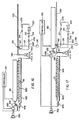
- Figure 17 is a view in elevation of the fifth embodiment printer,
this view showing the print head having been moved into position to clean the
print head.
-
DETAILED DESCRIPTION OF THE INVENTION
-
The present description will be directed in particular to elements
forming part of, or cooperating more directly with, apparatus in accordance with
the present invention. It is to be understood that elements not specifically shown
or described may take various forms well known to those skilled in the art.
-
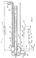
Therefore, referring to Figs. 1 and 2, there is shown a first
embodiment ink jet printer, generally referred to as 10, for printing an image 20
(shown in phantom) on a receiver 30 (also shown in phantom), which may be a
reflective-type receiver (e.g., paper) or a transmissive-type receiver (e.g.,
transparency). Receiver 30 is supported on a platen roller 40 capable of being
rotated by a platen roller motor 50 engaging platen roller 40. Thus, when platen
roller motor 50 rotates platen roller 40, receiver 30 will advance in a direction
illustrated by a first arrow 55. Platen roller 40 is adapted to pivot outwardly about
a pivot shaft 57 along an arc 59 for reasons disclosed hereinbelow. Many designs
for feeding paper for printing are possible. Another mechanism utilizes a first set
of feed rollers to dispose receiver onto a plate for printing. A second set of feed
rollers remove the receiver when printing is completed.
-
Referring to Figs. 1, 3 and 4, printer 10 also comprises a
reciprocating print head 60 disposed adjacent to platen roller 40. Print head 60
includes a plurality of ink channels 70 formed therein (only six of which are
shown), each channel 70 terminating in a channel outlet 75. In addition, each
channel 70, which is adapted to hold an ink body 77 therein, is defined by a pair of
oppositely disposed parallel side walls 79a and 79b. Print head 60 may further
include a cover plate 80 having a plurality of orifices 90 formed therethrough
colinearly aligned with respective ones of channel outlets 75, such that each
orifice 90 faces receiver 30. A surface 95 of cover plate 80 surrounds all orifices
90 and also faces receiver 30. Of course, in order to print image 20 on receiver 30,
an ink droplet 100 is released from ink channel 70 through orifice 90 in direction
of receiver 30 along a preferred axis 105 normal to surface 95, so that droplet 100
is suitably intercepted by receiver 30. To achieve this result, print head 60 may be
a "piezoelectric ink jet" print head formed of a piezoelectric material, such as lead
zirconium titanate (PZT). Such a piezoelectric material is mechanically
responsive to electrical stimuli so that side walls 79a/b simultaneously inwardly
deform when electrically stimulated. When side walls 79a/b simultaneously
inwardly deform, volume of channel 70 decreases to squeeze ink droplet 100 from
channel 70 and through orifice 90.
-
Referring again to Figs. 1, 3 and 4, a transport mechanism,
generally referred to as 110, is connected to print head 60 for reciprocating print
head 60 between a first position 115a thereof and a second position 115b (shown
in phantom). In this regard, transport mechanism 110 reciprocates print head 60 in
direction of a second arrow 117. Print head 60 slidably engages an elongate guide
rail 120, which guides print head 60 parallel to platen roller 40 while print head 60
is reciprocated. Transport mechanism 110 also comprises a drive belt 130
attached to print head 60 for reciprocating print head 60 between first position
115a and second position 115b, as described presently. In this regard, a reversible
drive belt motor 140 engages belt 130, such that belt 130 reciprocates in order that
print head 60 reciprocates with respect to platen 40. Moreover, an encoder strip
150 coupled to print head 60 monitors position of print head 60 as print head 60
reciprocates between first position 115a and second position 115b. In addition, a
controller 160 is connected to platen roller motor 50, drive belt motor 140,
encoder strip 150 and print head 60 for controlling operation thereof to suitably
form image 20 on receiver 30. Such a controller may be a Model CompuMotor
controller available from Parker Hannifin, Incorporated located in Rohnert Park,
California, U.S.A.
-
As best seen in Fig. 4, it has been observed that surface 95 may
have contaminant thereon, such as particulate matter 165. Such particulate matter
165 also may partially or completely obstruct orifice 90. Particulate matter 165
may be, for example, particles of dirt, dust, metal and/or encrustations of dried
ink. The contaminant may also be an unwanted film (e.g., grease, oxide, or the
like). Although the description herein refers to particulate matter, it is to be
understood that the invention pertains to such unwanted film, as well. Presence of
particulate matter 165 is undesirable because when particulate matter 165
completely obstructs orifice 90, ink droplet 100 is prevented from being ejected
from orifice 90. Also, when particulate matter 165 partially obstructs orifice 90,
flight of ink droplet 105 may be diverted from preferred axis 105 to travel along a
non-preferred axis 167 (as shown). If ink droplet 100 travels along non-preferred
axis 167, ink droplet 100 will land on receiver 30 in an unintended location. In
this manner, such complete or partial obstruction of orifice 90 leads to printing
artifacts such as "banding", a highly undesirable result. Also, presence of
particulate matter 165 on surface 95 may alter surface wetting and inhibit proper
formation of droplet 100. Therefore, it is desirable to clean (i.e., remove)
particulate matter 165 to avoid printing artifacts and improper formation of droplet
100.
-
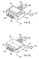
Referring to Figs. 3, 5, 6, 7A, 8A and 8B, first embodiment
cleaning block 175 includes a solvent delivering wiper 210 with a transducer 180
mounted atop the wiper. Wiper 210 has a first set of multiple internal areaways
220 formed therethrough. Solvent delivering wiper 210 is oriented with respect to
surface 95 such that first areaways 220 are alignable with surface 95 for reasons
disclosed presently. In this regard, first areaways 220 are alignable with surface
95 for delivering a liquid solvent cleaning agent to surface 95 in order to flush
particulate matter 165 from surface 95 (as shown). Of course, particulate matter
165 will be entrained in the solvent as the solvent flushes particulate matter 165
from surface 95. Wiper 210 may also include a blade portion 225 integrally
formed therewith for lifting contaminant 165 from surface 95 as cleaning wiper
blade 210 traverses surface 95 in direction of a third arrow 227. The transducer
180 is mounted atop the cleaning wiper blade 210 by any suitable means known in
the art, such as by a suitable screw fastener (not shown). The transducer has a
wire harness 195 extending from it, leading to a controller 190. The transducer is
driven via the controller, which produces a mechanical vibration in the cleaning
wiper blade 210. This mechanical vibration produces a shearing type effect in the
blade portion 225 as it transverses the printhead surface 95, which aids in the
removal of stubborn particulate matter 165. It may be understood that wicking
channels 230 and a second set of multiple internal cuts 240 in combination with
vacuum pump 290 co-act to remove solvent and particulate matter 165 which may
have been left by blade portion 225 as blade portion 225 traverses surface 95 (as
shown).
-
As best seen in Fig. 7, a second embodiment cleaning block 242
includes a solvent delivering wiper 210 with a transducer 180 mounted internal to
the wiper. The second embodiment cleaning block 242 serves the same function
as first embodiment cleaning block 235 with the only exception being in the
placement and functionality of transducer 180. In the second embodiment, the
transducer 180 is mounted internal to solvent delivering wiper 210 and serves as
an extra means of controlling the solvent flow through first set of multiple internal
areaways 220. The transducer is activated via controller 190 and wiring harness
195, and is capable of controlling the solvent delivered to the surface 95.
-
As best seen in Fig. 7C, a third embodiment cleaning block 244
includes a solvent delivering wiper 210, a solvent manifold 200 and transducer
180 mounted behind the solvent manifold. The third embodiment cleaning block
244 serves the same function as first embodiment cleaning block 235 and second
embodiment 242. In the third embodiment, solvent manifold 200 is attached to
the solvent delivering wiper 210 by any suitable means known in the art, such as
by a suitable screw fastener (not shown). Attached to the rear of manifold 200 is
transducer 180 also connected by any suitable means known in the art, such as by
a suitable screw fastener (not shown). The transducer is connected to and
controlled by controller 190 via wiring harness 195. When the transducer is
activated, it ultrasonically energizes the solvent in the manifold. The solvent is
ejected onto surface 95 and the removal of particulate 165 is enhanced by the
energized solvent.
-
Fig 8A shows first embodiment cleaning block 175 in a scraping
mode defined as having an angle less than 90 degrees. Fig. 8B shows first
embodiment cleaning block 175 in a wiping mode defined as having an angle
greater than 90 degrees.
-
Returning to Figs. 3, 5, 6, 7A, 7B, 8A, and 8B, a piping circuit,
generally referred to as 250, is associated with print head 60 for reasons disclosed
momentarily. In this regard, piping circuit 250 includes a first piping segment
260 coupled to first areaway 220 formed through wiper 210. A discharge pump
270 is connected to first piping segment 260 for discharging the solvent into first
piping segment 260. In this manner, the solvent discharges into first set of
areaways 220 formed within the wiper 210 and onto surface 95 while discharge
pump 270 discharges the solvent into first piping segment 260. It may be
appreciated that the solvent discharged onto surface 95 is chosen such that the
solvent also, at least in part, acts as lubricant to lubricate surface 95. Surface 95 is
lubricated in this manner, so that previously mentioned blade portion 225 will not
substantially mar, scar, or otherwise damage surface 95 and any electrical circuitry
which may be present on surface 95. In addition, a second piping segment 280 is
coupled to a second set of cuts 240 formed within the wiper 210. A vacuum pump
290 is connected to second piping segment 280 for inducing negative pressure
(i.e., pressure less than atmospheric pressure) in second piping segment 280.
Thus, negative pressure is induced in second set of cuts 240 and in second piping
segment 280. As negative pressure is induced on second piping segment 280, the
solvent and entrained particulate matter 165 are vacuumed from surface 95 to
enter second set of cuts 240.
-
Referring now to third embodiment cleaning block 244, shown in
Fig. 7C, the piping circuit generally referred to as 250 is similar to that in the first
and second embodiments previously discussed in detail. The difference in the
third embodiment is that first piping segment 260 is coupled to the first set of
multiple internal areaways 220 via a passageway internal to solvent manifold 200.
Likewise, second piping segment 280 is coupled to the second set of multiple
internal cuts 240 via a passageway internal to solvent manifold 200. It should be
noted that the two passageways in manifold 200 are unconnected, with one being
used for the fresh solvent introduced to the wiper and the other used for the "dirty"
solvent sucked from surface 95.
-
Referring yet again to Figs. 3, 5, 6, 7A, 7B, 7C, 8A, and 8B,
interposed between first piping segment 260 and second piping segment 280 is a
solvent supply reservoir 300 having a supply of the solvent therein. Discharge
pump 270, which is connected to first piping segment 260, draws the solvent from
reservoir 300 and discharges the solvent into second areaways 220 by means of
first piping circuit 260. Hence, it may be appreciated that first piping circuit 260
extends from wiper 210 to reservoir 300. In addition, vacuum pump 290, which is
connected to second piping segment 280, pumps the solvent and particulate matter
165 from print head surface 95 toward reservoir 300. Connected to second piping
segment 280 and interposed between vacuum pump 290 and reservoir 300 is a
filter 310 for capturing (i.e., separating-out) particulate matter 165 from the
solvent, so that the solvent supply in reservoir 300 is free of particulate matter
165. Of course, when filter 310 becomes saturated with particulate matter 165,
filter 310 is replaced by an operator of printer 10. Thus, circuit 250 defines a
recirculation loop for recirculating contaminant-free solvent across surface 95 to
efficiently clean surface 95. In addition, connected to first segment 260 is a first
valve 314, which first valve 314 is interposed between wiper 210 and discharge
pump 270. Moreover, connected to second segment 280 is a second valve 316,
which second valve 316 is interposed between reservoir 300 and vacuum pump
290. Presence of first valve 314 and second valve 316 make it more convenient
to perform maintenance on cleaning mechanism 170. That is, first valve 314 and
second valve 316 allow cleaning mechanism 170 to be easily taken out-of service f
or maintenance. For example, to replace filter 310, discharge pump 270 is shut-off
and first valve 314 is closed. Vacuum pump 290 is operated until solvent and
particulate matter are substantially evacuated from second piping segment 280. At
this point, second valve 316 is closed and vacuum pump 290 is shut-off. Next,
saturated filter 310 is replaced with a clean filter 310. Thereafter, cleaning
mechanism 170 is returned to service substantially in reverse to steps used to take
cleaning mechanism 170 out-of service.
-
Still referring to Figs. 3, 5, 6, 7A, 8A, and 8B, a translation
mechanism, generally referred to as 320, is connected to cleaning block 175 for
translating cleaning block 175 across surface 95 of print head 60. In this regard,
translation mechanism 320 comprises an elongate externally threaded lead-screw
330 threadably engaging cleaning block 175. Engaging lead-screw 330 is a motor
340 capable of rotating lead-screw 330, so that cleaning block 175, traverses
surface 95 as lead-screw 330 rotates. In this regard, cleaning block 175 traverses
surface 95 in direction of a fourth arrow 345. In addition, cleaning block 175 is
capable of being translated to any location on lead-screw 330, which preferably
extends the length of guide rail 120. Being able to translate cleaning block 175 to
any location on lead-screw 330 allows cleaning block 175 to clean print head 60
wherever print head 60 is located on guide rail 120. Moreover, connected to
motor 340 is a displacement mechanism 350 for displacing cleaning block 175 to
a position proximate surface 95 of print head 60.
-
Referring now to Figs. 2, 3 and 5, platen roller 40 is disposed
adjacent to print head 60 and, unless appropriate steps are taken, will interfere
with displacing cleaning block 175 to a position proximate surface 95. Therefore,
it is desirable to move platen roller 40 out of interference with cleaning block 175
so that cleaning block 175 can be displaced proximate surface 95. Therefore,
according to the first embodiment of printer 10, platen roller 40 is pivoted
outwardly about previously mentioned pivot shaft 57 along arc 59. After platen
roller 40 has been pivoted, displacement mechanism 350 is operated to displace
cleaning block 175 to a position proximate surface 95 to begin removal of
particulate matter 165 from ink channel 70 and surface 95.
-
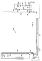
Turning now to Figs. 9 and 10, there is shown a second
embodiment ink jet printer 360 capable of simultaneously removing particulate
matter 165 from ink channel 70 and surface 95. Second embodiment ink jet
printer 360 is substantially similar to first embodiment ink jet printer 10, except
that platen roller 40 is fixed (i.e., non-pivoting). Also, according to this second
embodiment printer, print head 60 pivots about a pivot pin 370 to an upright
position (as shown). Moreover, cleaning mechanism 170 is oriented in an upright
position (as shown) and displacement mechanism 350 displaces cleaning block
175, so that cleaning block is moved to a location proximate surface 95.
-
Referring to Figs. 11 and 12, there is shown a third embodiment ink
jet printer 400 capable of simultaneously removing particulate matter 165 from ink
channel 70 and surface 95. Third embodiment ink jet printer 400 is substantially
similar to first embodiment ink jet printer 10, except that platen roller 40 is fixed
(i.e., non-pivoting). Also, according to this third embodiment printer, print head
60 pivots about pivot pin 370 to an upright position (as shown) and displacement
mechanism 350 displaces printer 400 (except for platen roller 40), so that printer
400 is moved to a location proximate cleaning mechanism 170. Moreover,
cleaning mechanism 170 is oriented in a fixed upright position (as shown).
-
Referring to Figs. 13 and 14, there is shown a fourth embodiment
ink jet printer 410 capable of simultaneously removing particulate matter 165 from
ink channel 70 and surface 95. Fourth embodiment ink jet printer 410 is
substantially similar to first embodiment ink jet printer 10, except that platen roller
40 is fixed (i.e., non-pivoting) and cleaning assembly 170 is off-set from an end
portion of platen roller 40 by a distance "X". Also, according to this third
embodiment printer, displacement mechanism 350 displaces printer 410 (except
for platen roller 40), so that printer 410 is moved to a location proximate cleaning
mechanism 170.
-
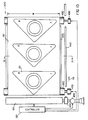
Referring to Figs. 15, 16 and 17, there is shown a fifth embodiment
ink jet printer, generally referred to as 420, for printing image 20 on receiver 30.
Second printer 400 is a so-called "page-width" printer capable of printing across
width W of receiver 30 without reciprocating across width W. That is, printer 420
comprises print head 60 of length substantially equal to width W. Connected to
print head 60 is a carriage 430 adapted to carry print head 60 in direction of first
arrow 55. In this regard, carriage 430 slidably engages an elongate slide member
440 extending parallel to receiver 30 in direction of first arrow 55. A print head
drive motor 450 is connected to carriage 430 for operating carriage 430, so that
carriage 430 slides along slide member 440 in direction of first arrow 55. As
carriage 430 slides along slide member 440 in direction of first arrow 55, print
head 60 also travels in direction of first arrow 55 because print head 60 is
connected to carriage 430. In this manner, print head 60 is capable of printing a
plurality of images 20 (as shown) in a single printing pass along length of receiver
30. In addition, a first feed roller 460 engages receiver 30 for feeding receiver 30
in direction of first arrow 55 after all images 20 have been printed. In this regard,
a first feed roller motor 470 engages first feed roller 460 for rotating first feed
roller 460, so that receiver 30 feeds in direction of first arrow 55. Further, a
second feed roller 480, spaced-apart from first feed roller 460, may also engage
receiver 30 for feeding receiver 30 in direction of first arrow 55. In this case, a
second feed roller motor 490, synchronized with first feed roller motor 470,
engages second feed roller 480 for rotating second feed roller 480, so that receiver
30 smoothly feeds in direction of first arrow 55. Interposed between first feed
roller 460 and second feed roller 480 is a support member, such as a stationary flat
platen 500, for supporting receiver 30 thereon as receiver feeds from first feed
roller 460 to second feed roller 480. Of course, previously mentioned controller
160 is connected to print head 60, print head drive motor 450, first feed roller
motor 470 and second feed roller motor 490 for controlling operation thereof in
order to suitably form images 20 on receiver 30.
-
Still referring to Figs. 15, 16 and 17, according to this fifth
embodiment printer 420, displacement mechanism 350 displaces printer 410
(except for feed rollers 460/480 and platen 500), so that printer 410 is moved to a
location proximate cleaning mechanism 170.
-
The solvent cleaning agent mentioned hereinabove may be any
suitable liquid solvent composition, such as water, isopropanol, diethylene glycol,
diethylene glycol monobutyl ether, octane, acids and bases, surfactant solutions
and any combination thereof. Complex liquid compositions may also be used,
such as microemulsions, micellar surfactant solutions, vesicles and solid particles
dispersed in the liquid.
-
It may be understood from the teachings hereinabove, that an
advantage of the present invention is that cleaning time is reduced. This is so
because surface 95 of print head 60 is cleaned of contaminant simultaneously with
cleaning ink channels 70 formed in the print head 60.
-
While the invention has been described with particular reference to
its preferred embodiments, it will be understood by those skilled in the art that
various changes may be made and equivalents may be substituted for elements of
the preferred embodiments without departing from the invention. For example,
with respect to the second embodiment printer 360, displacement mechanism 350
may be foldable to the upright position from a substantially horizontal position.
This configuration of the invention will minimize the external envelope of printer
360 when print head 60 is not being cleaned by cleaning mechanism 170, so that
printer 360 can be located in a confined space with limited headroom.
-
Therefore, what is provided is an ink jet printer with cleaning
mechanism having a wiper blade and transducer, and method of assembling the
printer, which cleaning mechanism is capable of simultaneously cleaning the print
head surface and ink channels.