EP1016608A1 - Rewinding method and machine for making logs of paper web and the like - Google Patents
Rewinding method and machine for making logs of paper web and the like Download PDFInfo
- Publication number
- EP1016608A1 EP1016608A1 EP98830813A EP98830813A EP1016608A1 EP 1016608 A1 EP1016608 A1 EP 1016608A1 EP 98830813 A EP98830813 A EP 98830813A EP 98830813 A EP98830813 A EP 98830813A EP 1016608 A1 EP1016608 A1 EP 1016608A1
- Authority
- EP
- European Patent Office
- Prior art keywords
- web
- roller
- winding
- cutting
- counter support
- Prior art date
- Legal status (The legal status is an assumption and is not a legal conclusion. Google has not performed a legal analysis and makes no representation as to the accuracy of the status listed.)
- Granted
Links
- 238000000034 method Methods 0.000 title claims abstract description 14
- 238000004804 winding Methods 0.000 claims abstract description 85
- 238000005520 cutting process Methods 0.000 claims abstract description 58
- 238000011144 upstream manufacturing Methods 0.000 claims abstract description 7
- 238000004519 manufacturing process Methods 0.000 claims abstract description 3
- 239000004745 nonwoven fabric Substances 0.000 claims abstract description 3
- 238000007664 blowing Methods 0.000 claims description 3
- 230000001133 acceleration Effects 0.000 claims 1
- 230000000694 effects Effects 0.000 description 2
- 230000006978 adaptation Effects 0.000 description 1
- 230000002411 adverse Effects 0.000 description 1
- 230000005540 biological transmission Effects 0.000 description 1
- 239000000463 material Substances 0.000 description 1
- 238000012986 modification Methods 0.000 description 1
- 230000004048 modification Effects 0.000 description 1
- 238000003825 pressing Methods 0.000 description 1
- 230000001360 synchronised effect Effects 0.000 description 1
Images


Classifications
-
- B—PERFORMING OPERATIONS; TRANSPORTING
- B65—CONVEYING; PACKING; STORING; HANDLING THIN OR FILAMENTARY MATERIAL
- B65H—HANDLING THIN OR FILAMENTARY MATERIAL, e.g. SHEETS, WEBS, CABLES
- B65H19/00—Changing the web roll
- B65H19/22—Changing the web roll in winding mechanisms or in connection with winding operations
- B65H19/26—Cutting-off the web running to the wound web roll
-
- B—PERFORMING OPERATIONS; TRANSPORTING
- B65—CONVEYING; PACKING; STORING; HANDLING THIN OR FILAMENTARY MATERIAL
- B65H—HANDLING THIN OR FILAMENTARY MATERIAL, e.g. SHEETS, WEBS, CABLES
- B65H2301/00—Handling processes for sheets or webs
- B65H2301/40—Type of handling process
- B65H2301/41—Winding, unwinding
- B65H2301/414—Winding
- B65H2301/4148—Winding slitting
- B65H2301/4149—Winding slitting features concerning supply of cores
-
- B—PERFORMING OPERATIONS; TRANSPORTING
- B65—CONVEYING; PACKING; STORING; HANDLING THIN OR FILAMENTARY MATERIAL
- B65H—HANDLING THIN OR FILAMENTARY MATERIAL, e.g. SHEETS, WEBS, CABLES
- B65H2301/00—Handling processes for sheets or webs
- B65H2301/40—Type of handling process
- B65H2301/41—Winding, unwinding
- B65H2301/417—Handling or changing web rolls
- B65H2301/418—Changing web roll
- B65H2301/4181—Core or mandrel supply
- B65H2301/41816—Core or mandrel supply by core magazine within winding machine, i.e. horizontal or inclined ramp holding cores
-
- B—PERFORMING OPERATIONS; TRANSPORTING
- B65—CONVEYING; PACKING; STORING; HANDLING THIN OR FILAMENTARY MATERIAL
- B65H—HANDLING THIN OR FILAMENTARY MATERIAL, e.g. SHEETS, WEBS, CABLES
- B65H2301/00—Handling processes for sheets or webs
- B65H2301/40—Type of handling process
- B65H2301/41—Winding, unwinding
- B65H2301/417—Handling or changing web rolls
- B65H2301/418—Changing web roll
- B65H2301/4182—Core or mandrel insertion, e.g. means for loading core or mandrel in winding position
- B65H2301/41826—Core or mandrel insertion, e.g. means for loading core or mandrel in winding position by gripping or pushing means, mechanical or suction gripper
-
- B—PERFORMING OPERATIONS; TRANSPORTING
- B65—CONVEYING; PACKING; STORING; HANDLING THIN OR FILAMENTARY MATERIAL
- B65H—HANDLING THIN OR FILAMENTARY MATERIAL, e.g. SHEETS, WEBS, CABLES
- B65H2301/00—Handling processes for sheets or webs
- B65H2301/40—Type of handling process
- B65H2301/41—Winding, unwinding
- B65H2301/417—Handling or changing web rolls
- B65H2301/4187—Relative movement of core or web roll in respect of mandrel
- B65H2301/4189—Cutting
- B65H2301/41892—Cutting knife located in winding or guiding roller and protruding therefrom
- B65H2301/418925—Cutting knife located in winding or guiding roller and protruding therefrom and cooperating with second assembly located in another roller
-
- B—PERFORMING OPERATIONS; TRANSPORTING
- B65—CONVEYING; PACKING; STORING; HANDLING THIN OR FILAMENTARY MATERIAL
- B65H—HANDLING THIN OR FILAMENTARY MATERIAL, e.g. SHEETS, WEBS, CABLES
- B65H2408/00—Specific machines
- B65H2408/20—Specific machines for handling web(s)
- B65H2408/23—Winding machines
- B65H2408/235—Cradles
Definitions
- the present invention relates to a rewinding method for making logs starting from a web, for example used for the production of rolls of toilet paper, rolls of all purpose wipers, household non woven fabric, industrial rolls and the like.
- the invention relates to a rewinding machine that carries out this method.
- Rewinding machines wherein a winding step is carried out on a log which is in contact surface with winding rollers. More precisely, the log is formed starting from a web of paper, continuous or with transversal perforations, which is carried by first dragging means, is wound partially on an upper winding roller, is in contact with a lower winding roller and is kept against the two upper and lower winding rollers by means of a pressure roller.
- the three rollers define a channel, or winding cradle, wherein the log is formed and the web of paper is supplied continuously and pulled by the surface frictional contact of the rollers on the log.
- the log is formed on a tubular core.
- a predetermined diameter normally calculated by checking the length of the developed paper, the web is cut or torn and the log is pushed away from the winding cradle at the side of the lower winding roller and, at the same time, a new core is supplied into the cradle by a pusher. It is possible, however, to wind the log without core as well.
- Some types of rewinding machines at the end of each roll winding step, provide a blade that cuts transversally the web by pressing against the upper winding roller.
- the upper winding roller has one or more cutting slits with which a retractable blade engages mounted on an adjacent cutting roller. This system has the drawback that it does not allow cuts having length not multiple of the circumference of the upper winding roller, or not multiple of the distance between two successive cutting slits when several cutting slits are provided for.
- rolls can be obtained whose development is multiple of the pitch between two transversal perforations only.
- rolls without transversal perforations for example industrial rolls, in order to effect the tearing it is necessary to make a special auxiliary perforation on the web at the end of the development of each roll.
- the web winding method for making a log whose characteristic is that it comprises the steps of:
- the front end is pulled towards the winding cradle by a suction step carried out by the counter support roller.
- the winding cradle comprises an upper winding roller, a lower winding roller and a pressure roller, the upper winding roller comprising suction means for capturing at least the front end of the web and starting the winding of the new log.
- the upper winding roller has a plurality of radial holes, the front end of the web being captured by a predetermined sector of said holes belonging to an outer drum by means of an inner drum rotatable coaxially but in a way independent from the outer drum and suitable for selectively connecting the predetermined sector of the holes with a suction chamber.
- the synchronisation between the inner drum, the cutting roller and the counter support roller is obtained by a control step of driven axes operated by a computer, whereby, for every chosen web development between two successive cuts the computer arranges a reset phase of the counter support roller with respect to the blade and a relative rotation between the outer drum and the inner drum.
- a rewinding apparatus of a web for making logs comprises:
- the cutting blade urges against the counter support roller for cutting the web creating a tail end of the previous log and a front end of a new log.
- the counter support roller comprises suction means for dragging the front end towards the winding cradle.
- the winding cradle comprises an upper winding roller, a lower winding roller and a pressure roller, the upper winding roller comprising means for capturing the front end of the web, said means for capturing may be suction means.
- the upper winding roller comprises preferably an outer drum having a plurality of holes and an inner drum rotatable independently from the outer drum and suitable for connecting a predetermined sector of the holes with a suction chamber, whereby it is possible in turn to capture the front end by means of a predetermined sector of the outer drum.
- the inner drum, the counter support roller and the cutting roller are brought into rotation by axes driven by at least a motor operated by a control unit that adjusts the cutting length of the web of said log, the motor decelerating or accelerating the rotation of said axes and causing said counter support roller to slide with respect to said web.
- the counter support roller has a surface with a plurality of small air blowing holes for reducing further the friction with respect to said web during the sliding step.
- a rewinding apparatus of a web 1 for making a log 2a comprises a feeding roller 3 of web 1 and, downstream of it, a winding cradle 4 wherein log 2a is wound.
- Cradle 4 comprises an upper winding roller 5, a lower winding roller 6 and a pressure roller 7.
- the latter follows the growth of log 2a with the tasks of assuring its continuous contact with winding rollers 5 and 6 and of controlling its diameter growth.
- a counter support roller 8 is provided on which web 1 rests.
- Counter support roller 8 is driven independently and has at least a cutting slit 9 in which a retractable blade 10 of a cutting roller 11 can engage.
- Cutting roller 11 brings periodically blade 10 against counter support roller 8 at the slit 9 for cutting web 1. When the cut has not to be carried out blade 11 retracts for not causing an undesired cut of the paper.
- blade 10 urges against counter support roller 8 for cutting web 1 creating a tail end 1a of previous log 2a and a front end 1b of a new log.
- counter support roller 8 has suction holes 12a and 12b along the edges of slit 9, suitable for capturing and dragging respectively tail end 1a and front end 1b of web 1.
- upper winding roller 5 comprises suction means comprising an outer drum 14 having a plurality of holes 15 and an inner drum 16 rotatable coaxially and independently from outer drum 14 and suitable for connecting, by means of radial walls 17, a chosen sector S of holes 15 with a suction chamber 18. This way it is possible in turn to capture front end 1b by means of a different chosen sector S of holes 15 of outer drum 14.
- Log 2a already wound is dragged continuously rotating within cradle 4 by tangential friction against upper winding roller 5, lower winding roller 6 and pressure roller 7.
- the winding started about a core 20a, which had been supplied into cradle 4 by a loading unit 21 that draws cores 20 from a chute guide 22.
- a core 20b is ready for being wound around to form a log starting from front end 1b of web 1.
- Counter support roller 8 has a smooth surface, continuous or discontinued by circumferential grooves, for providing a support to web 1, for allowing the cutting or tearing and for permitting, at predetermined moments, the sliding of the web thereon.
- its surface can also have a plurality of small air blowing holes.
- the winding steps of web 1 for making a log 2a are the following.
- the web of paper 1 is supplied into winding cradle 4 about core 20a up to a chosen length development predetermined upstream of feeding roller 3.
- counter support roller 8 slides relatively to web 1, rotating of a relative angle 23a without braking or accelerating the web, since there is only a slight friction between web 1 and roller 8 surface. Also cutting roller 11 and inner drum 16, in a way independent from outer drum 14, make a relative rotation 24a and 25a of equal linear development with respect to the movement of web 1.
- the synchronisation between inner drum 14, cutting roller 11 and counter support roller 8 is obtained by means of a control of the axes 23, 24 and 25 operated by the CPU 26, not shown in more detail since easily obtainable by a man of the art. Therefore, for every length of web chosen between two following cuts, CPU 26 arranges the phase reset of counter support roller 8 with respect to web 1, calculating the speed of the same for example starting from the speed of axis 27 of feeding roller 3 in synchronism with a relative rotation of cutting roller 11 and of inner drum 16 with respect to outer drum 14.
- the three axes are driven by distinct motors, for example DC motors, even of brushless type, and brought into rotation in synchronism by CPU 26, which always operates their rotation responsive to the speed of web 1.
- DC motors for example DC motors, even of brushless type
- counter support roller 8 has more than one cutting slit 9 for reducing further the time during which the web slides on roller 8
Abstract
Description
- The present invention relates to a rewinding method for making logs starting from a web, for example used for the production of rolls of toilet paper, rolls of all purpose wipers, household non woven fabric, industrial rolls and the like.
- Furthermore, the invention relates to a rewinding machine that carries out this method.
- Rewinding machines are known wherein a winding step is carried out on a log which is in contact surface with winding rollers. More precisely, the log is formed starting from a web of paper, continuous or with transversal perforations, which is carried by first dragging means, is wound partially on an upper winding roller, is in contact with a lower winding roller and is kept against the two upper and lower winding rollers by means of a pressure roller. The three rollers define a channel, or winding cradle, wherein the log is formed and the web of paper is supplied continuously and pulled by the surface frictional contact of the rollers on the log.
- Normally, in the winding cradle the log is formed on a tubular core. Once the log has reached a predetermined diameter, normally calculated by checking the length of the developed paper, the web is cut or torn and the log is pushed away from the winding cradle at the side of the lower winding roller and, at the same time, a new core is supplied into the cradle by a pusher. It is possible, however, to wind the log without core as well.
- Some types of rewinding machines, at the end of each roll winding step, provide a blade that cuts transversally the web by pressing against the upper winding roller. The upper winding roller has one or more cutting slits with which a retractable blade engages mounted on an adjacent cutting roller. This system has the drawback that it does not allow cuts having length not multiple of the circumference of the upper winding roller, or not multiple of the distance between two successive cutting slits when several cutting slits are provided for.
- In the case, instead, of rewinding machines in which the web is torn, there is the drawback that the tearing step is subject to being carried out incorrectly. Actually, the web is stopped upstream of, or onto, the upper winding roller and the tearing is caused by the pulling action, on the web kept still, of the lower winding roller, on which the log is pushed by the pressure roller. Normally, it is sufficient to create a speed difference between said two rollers at the moment of the exchange in order to effect the tearing. However, the tearing sometimes cannot be made correctly, since it depends on the correct growth of the log being wound as well as on the presence and quality of the transversal perforation. Furthermore, with the tearing method rolls can be obtained whose development is multiple of the pitch between two transversal perforations only. Finally, in case of rolls without transversal perforations, for example industrial rolls, in order to effect the tearing it is necessary to make a special auxiliary perforation on the web at the end of the development of each roll.
- It is an object of the present invention to provide a rewinding method of a web of paper for making logs, wherein the passage from a roll to the successive one is carried out by cutting the web and wherein the development of the web wound on the log after the cutting step has whichever desired length.
- It is another object of the present invention to provide a rewinding machine of a web of paper for making logs that is capable of cutting the web upstream the winding zone in a desired location.
- These and other objects are achieved by the web winding method for making a log whose characteristic is that it comprises the steps of:
- feeding a web of paper in a winding cradle;
- arranging upstream of the cradle a counter support roller that comprises at least a cutting slit transversal to the web;
- arranging a cutting roller that faces the counter support roller and comprises at least a blade transversal to the web, the web running between the counter support roller and the cutting roller;
- cutting or locally tearing the web for contact of the blade with the web in a predetermined moment at the slit of the counter support roller, the cut creating in the web a tail end and a front end;
- concluding the winding of the log that comprises the tail end and introducing the front end in the cradle for starting the winding of a new log;
- winding the new log up to a predetermined development of the web;
- decelerating or accelerating the counter support roller making it slide on the web while winding the new log so that the blade is ready to cut the web at a desired chosen location.
- Preferably, the front end is pulled towards the winding cradle by a suction step carried out by the counter support roller.
- Always preferably, the winding cradle comprises an upper winding roller, a lower winding roller and a pressure roller, the upper winding roller comprising suction means for capturing at least the front end of the web and starting the winding of the new log.
- In a preferred embodiment, the upper winding roller has a plurality of radial holes, the front end of the web being captured by a predetermined sector of said holes belonging to an outer drum by means of an inner drum rotatable coaxially but in a way independent from the outer drum and suitable for selectively connecting the predetermined sector of the holes with a suction chamber.
- The synchronisation between the inner drum, the cutting roller and the counter support roller is obtained by a control step of driven axes operated by a computer, whereby, for every chosen web development between two successive cuts the computer arranges a reset phase of the counter support roller with respect to the blade and a relative rotation between the outer drum and the inner drum.
- According to another aspect of the present invention, a rewinding apparatus of a web for making logs comprises:
- means for feeding and dragging a web of paper;
- a winding cradle wherein the winding of the log is carried out downstream the means for feeding;
- a counter support roller on which the web lays located in the space interval between the means for feeding and the cradle, the counter support roller having at least a cutting slit;
- a cutting roller suitable for bringing periodically a cutting blade against the counter support roller at its slit for cutting the web;
- means for accelerating or decelerating the counter support roller and the cutting roller with respect to the web.
- The cutting blade urges against the counter support roller for cutting the web creating a tail end of the previous log and a front end of a new log. Preferably, the counter support roller comprises suction means for dragging the front end towards the winding cradle.
- Always preferably, the winding cradle comprises an upper winding roller, a lower winding roller and a pressure roller, the upper winding roller comprising means for capturing the front end of the web, said means for capturing may be suction means.
- The upper winding roller comprises preferably an outer drum having a plurality of holes and an inner drum rotatable independently from the outer drum and suitable for connecting a predetermined sector of the holes with a suction chamber, whereby it is possible in turn to capture the front end by means of a predetermined sector of the outer drum.
- In an advantageous embodiment of the invention the inner drum, the counter support roller and the cutting roller are brought into rotation by axes driven by at least a motor operated by a control unit that adjusts the cutting length of the web of said log, the motor decelerating or accelerating the rotation of said axes and causing said counter support roller to slide with respect to said web.
- In order to make the sliding lighter the counter support roller has a surface with a plurality of small air blowing holes for reducing further the friction with respect to said web during the sliding step.
- Further characteristics and/or advantages of the rewinding method and of the rewinding apparatus according to the present invention will be made clearer with the following description of an embodiment thereof, exemplifying but not limitative, with reference to attached drawings wherein:
- figure 1 shows a cross sectional view of a rewinding machine according to the present invention;
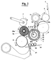
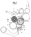
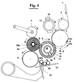
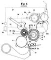
- figures from 2 to 5 show four different positions of the tail end of the web of the log being wound and of the front end of the web of the new log to be wound, as well as supplying steps of the core;
- figure 6 shows the position of the rewinding machine of the previous figures ready for a cut at the conclusion of a log winding phase and a diagrammatical view of the means for adjusting the cutting length.
- With reference to figure 1, a rewinding apparatus of a
web 1 for making alog 2a comprises afeeding roller 3 ofweb 1 and, downstream of it, a windingcradle 4 whereinlog 2a is wound. -
Cradle 4, according to the prior art, comprises an upperwinding roller 5, alower winding roller 6 and apressure roller 7. The latter follows the growth oflog 2a with the tasks of assuring its continuous contact withwinding rollers - According to the invention, between
feeding roller 3 and upper winding roller 5 acounter support roller 8 is provided on whichweb 1 rests.Counter support roller 8 is driven independently and has at least acutting slit 9 in which aretractable blade 10 of acutting roller 11 can engage.Cutting roller 11 brings periodicallyblade 10 againstcounter support roller 8 at theslit 9 for cuttingweb 1. When the cut has not to be carried outblade 11 retracts for not causing an undesired cut of the paper. - At the conclusion of each log,
blade 10 urges againstcounter support roller 8 for cuttingweb 1 creating atail end 1a ofprevious log 2a and afront end 1b of a new log. - Always according to the invention,
counter support roller 8 hassuction holes slit 9, suitable for capturing and dragging respectivelytail end 1a andfront end 1b ofweb 1. Also upper windingroller 5 comprises suction means comprising anouter drum 14 having a plurality ofholes 15 and aninner drum 16 rotatable coaxially and independently fromouter drum 14 and suitable for connecting, by means ofradial walls 17, a chosen sector S ofholes 15 with asuction chamber 18. This way it is possible in turn to capturefront end 1b by means of a different chosen sector S ofholes 15 ofouter drum 14. -
Log 2a already wound is dragged continuously rotating withincradle 4 by tangential friction against upper windingroller 5,lower winding roller 6 andpressure roller 7. The winding started about acore 20a, which had been supplied intocradle 4 by aloading unit 21 that drawscores 20 from achute guide 22. In particular, acore 20b is ready for being wound around to form a log starting fromfront end 1b ofweb 1. -
Counter support roller 8 has a smooth surface, continuous or discontinued by circumferential grooves, for providing a support toweb 1, for allowing the cutting or tearing and for permitting, at predetermined moments, the sliding of the web thereon. In order to make easier the sliding for certain types of web having a greater friction factor its surface can also have a plurality of small air blowing holes. - The winding steps of
web 1 for making alog 2a are the following. - The web of
paper 1 is supplied into windingcradle 4 aboutcore 20a up to a chosen length development predetermined upstream of feedingroller 3. - Then, as shown in figure 1, after that a desired amount of
web 1 has been developed upstream ofcradle 4,counter support roller 8, at cuttingslit 9, andtransversal blade 10 of cuttingroller 11 cut or tearweb 1 separatingtail end 1a fromfront end 1b. Cutting or tearing are equivalent at this stage since, with the presence of transversal perforations on the web, the action of the blade makes easier the tearing, whereas without perforation the blade carries out an actual cutting. - Then the various steps of bringing the front end towards the cradle are successively carried out, and precisely:
-
suction holes tail end 1a andfront end 1b allowing to countersupport roller 8 to pull them (fig. 2) up to bring them into contact with upper windingroller 5; - then, holes 15 of
outer drum 14 of upper windingroller 5, at the sector S for draggingfront end 1b, become active owing to the position ofwalls 17 of the inner drum 16 (fig. 3) and taketail end 1a andfront end 1b; the latter is either folded, (like in figure 4) by means of suction by a portion of sector S at a certain distance from the transversal edge, or dragged just starting from the edge, according to how the outset of winding oncore 20b is made; - the rotation between
outer drum 14 andinner drum 16 is synchronous for bringing (fig. 4)front end 1b towardscradle 4; - at the same
time loading unit 21 pushes a core 20b oflog 2b so that this encounters (fig. 5)front end 1b at the entrance ofcradle 4, which is at the same time freed fromlog 2a already wound. - Once started winding
log 2b (fig. 6),inner drum 14,counter support roller 8 and cuttingroller 11, withblade 10 retracted (fig. 5) continue to rotate, up to the conclusion oflog 2b same. - Always as shown in figure 6, during the winding of
log 2binner drum 14,counter support roller 8 and cuttingroller 11, for going back to the starting position of figure 1, by means of a check on the rotation of theiraxes web 1, but do different rotations, variable in turn according to the position of the cut to make. - More precisely,
counter support roller 8 slides relatively toweb 1, rotating of arelative angle 23a without braking or accelerating the web, since there is only a slight friction betweenweb 1 androller 8 surface. Also cuttingroller 11 andinner drum 16, in a way independent fromouter drum 14, make arelative rotation web 1. - The synchronisation between
inner drum 14, cuttingroller 11 andcounter support roller 8 is obtained by means of a control of theaxes CPU 26, not shown in more detail since easily obtainable by a man of the art. Therefore, for every length of web chosen between two following cuts,CPU 26 arranges the phase reset ofcounter support roller 8 with respect toweb 1, calculating the speed of the same for example starting from the speed ofaxis 27 of feedingroller 3 in synchronism with a relative rotation of cuttingroller 11 and ofinner drum 16 with respect toouter drum 14. - It is possible, as shown diagrammatically in figure 6, that axes 23, 24 and 25 of
counter support roller 8, of cuttingroller 11 and ofinner drum 16 are driven by asingle motor 28 and connected by means of transmissions of suitable ratio,CPU 26 operating the rotation of the motor responsive to the speed ofweb 1. - Alternatively, the three axes are driven by distinct motors, for example DC motors, even of brushless type, and brought into rotation in synchronism by
CPU 26, which always operates their rotation responsive to the speed ofweb 1. - In both cases, the result is achieved that every log is wound with a web development having desired length. In fact, after rotation according to
angles CPU 26, there is the possibility of cutting the web at a chosen location. All this is done independently from the circumference ofroller 5 and without adversely affecting the winding phase of the log withincradle 4 byrollers - It is possible that counter
support roller 8 has more than one cutting slit 9 for reducing further the time during which the web slides onroller 8 - The foregoing description of a specific embodiment will so fully reveal the invention according to the conceptual point of view, so that others, by applying current knowledge, will be able to modify and/or adapt for various applications such an embodiment without further research and without parting from the invention, and it is therefore to be understood that such adaptations and modifications will have to be considered as equivalent to the specific embodiment. The means and the materials to realise the different functions described herein could have a different nature without, for this reason, departing from the field of the invention. It is to be understood that the phraseology or terminology employed herein is for the purpose of description and not of limitation.
Claims (16)
- Winding method of a web (1) for making a log (2a), in particular for the production of rolls of toilet paper, rolls of all purpose wipers or household non woven fabric, industrial rolls and the like, characterised in that it comprises the steps of:feeding a web (1) of paper in a winding cradle (4);arranging upstream of said cradle (4) a counter support roller (8) comprising at least a cutting slit (9) transversal to the web (1);arranging a cutting roller (11) that faces said counter support roller and comprises at least a blade (10) transversal to the web (1), said web running between said counter support roller (8) and said cutting roller (11);cutting or tearing said web (1) by contact of said blade (10) with said web (1) in a predetermined moment (8) at said slit (9), the cut or tearing creating in said web (1) a tail end (1a) and a front end (1b);conclusion of the winding of the log (2a) having said tail end (1a) and introducing said front end (1b) into said cradle (4) for starting the winding of a new log (2b);winding the new log (2b) up to a chosen length development of said web (1);rotation with sliding of said counter support roller (8) on said web (1) during the winding of said new log (2b) for allowing the blade (10) to cut the web in a desired chosen location.
- Winding method according to claim 1, wherein at least said front end (1b) is dragged towards said winding cradle (4) by a suction step (12a, 12b) carried out by said counter support roller (1).
- Winding method according to claim 1, wherein said winding cradle (4) comprises an upper winding roller (5), a lower winding roller (6) and a pressure roller (7), said upper winding roller (5) for starting the winding of said new log capturing by suction means at least said front end (1b) of said web (1).
- Winding method according to claim 3, wherein said upper winding roller (5) has a plurality of radial holes (15) made on an outer drum (14), said front end being captured by a chosen field (S) of holes (15) of said outer drum (14) by means of a co-axial inner drum (16) rotatable independently from the outer drum (14) and suitable for selectively connecting said chosen field (S) of said holes (15) with a suction chamber (18) present in said inner drum (16) .
- Winding method according to claim 4, wherein a step of synchronisation between said inner drum (16), said cutting roller (11) and said counter support roller (8) is provided whereby, for every chosen web length development between two successive cuts an acceleration or deceleration of said counter support roller (8), of said cutting roller (11) and of said inner drum (16) with respect to said web (1) is done.
- Winding method according to claim 5, wherein said step of synchronisation is obtained by means of a control operated by a computer (26) of the driven axes of rotation (23,24,25) of said counter support roller (8), of said cutting roller (11) and of said inner drum (16).
- Rewinding apparatus of a web for making a log comprising:means for feeding (3) and dragging a web (1);a winding cradle (4) within which said log (2a, 2b) grows downstream said means for feeding (3); characterised in that it comprisesa counter support roller (8) on which said web (1) rests in the space interval between said means for feeding (3) and said cradle (4), said counter support roller (8) having at least a cutting slit (9);a cutting roller (11) suitable for bringing periodically a cutting blade (10) against said counter support roller (8) at said slit (9) for cutting or tearing said web (1);means for decelerating or accelerating said cutting roller (11) and said counter support roller (8) between one cut or tear and the successive one.
- Rewinding apparatus according to claim 7, wherein said cutting blade (10) urges against said counter support roller (8) for cutting or tearing said web (1) creating a tail end (1a) of the previous log (2a) and a front end (1b) of a new log (2b).
- Rewinding apparatus according to claim 7, wherein said counter support roller (8) comprises means for dragging said tail end (1a) and said front end (1b) towards said winding cradle (4).
- Rewinding apparatus according to claim 9, wherein said means for dragging said tail end (1a) and said front end (1b) towards said cradle (4) comprises suction holes (12a, 12b).
- Rewinding apparatus according to claim 7, wherein said winding cradle (4) comprises an upper winding roller (5), a lower winding roller (6) and a pressure roller (7), said upper winding roller (5) comprising means for capturing at least said front end (1b) of said web (1).
- Rewinding apparatus according to claim 11, wherein said means for capturing at least said front end (1b) of said web (1) comprises suction means.
- Rewinding apparatus according to claim 11 or 12, wherein said upper winding roller comprises an outer drum (14) having a plurality of holes (15) and an inner coaxial drum (16) rotatable independently from the outer drum and comprising means (17) for connecting a predetermined sector (S) of said holes with a suction chamber (18), whereby it is possible in turn to capture at least said front end (1b) by means of a different chosen field (S) of said outer drum (14).
- Rewinding apparatus according to claim 12, wherein said inner drum (16), said counter support roller (8) and said cutting roller (11) are brought into rotation by driven axes (23,24,25) operated by at least a motor (28) operated by a control unit (26) that adjusts the cutting length of the web (1) of said log (2a, 2b), said motor (28) decelerating or accelerating the rotation of said axes (23,24,25) causing said counter support roller (8) to slide (23a) with respect to said web (1).
- Rewinding apparatus according to claim 11, wherein said counter support roller (8) has a low friction smooth surface, continuous or comprising a plurality of circumferential grooves.
- Rewinding apparatus according to claim 11, wherein said low friction smooth surface has a plurality of small air blowing holes.
Priority Applications (3)
| Application Number | Priority Date | Filing Date | Title |
|---|---|---|---|
| DE69819535T DE69819535T2 (en) | 1998-12-31 | 1998-12-31 | Rewinding method and apparatus for forming web rolls and the like |
| EP98830813A EP1016608B1 (en) | 1998-12-31 | 1998-12-31 | Rewinding method and machine for making logs of paper web and the like |
| US09/475,513 US6494398B1 (en) | 1998-12-31 | 1999-12-30 | Rewinding method and machine for making logs of paper and the like |
Applications Claiming Priority (1)
| Application Number | Priority Date | Filing Date | Title |
|---|---|---|---|
| EP98830813A EP1016608B1 (en) | 1998-12-31 | 1998-12-31 | Rewinding method and machine for making logs of paper web and the like |
Publications (2)
| Publication Number | Publication Date |
|---|---|
| EP1016608A1 true EP1016608A1 (en) | 2000-07-05 |
| EP1016608B1 EP1016608B1 (en) | 2003-11-05 |
Family
ID=8236956
Family Applications (1)
| Application Number | Title | Priority Date | Filing Date |
|---|---|---|---|
| EP98830813A Expired - Lifetime EP1016608B1 (en) | 1998-12-31 | 1998-12-31 | Rewinding method and machine for making logs of paper web and the like |
Country Status (3)
| Country | Link |
|---|---|
| US (1) | US6494398B1 (en) |
| EP (1) | EP1016608B1 (en) |
| DE (1) | DE69819535T2 (en) |
Cited By (6)
| Publication number | Priority date | Publication date | Assignee | Title |
|---|---|---|---|---|
| DE10119460A1 (en) * | 2001-04-17 | 2002-10-31 | Lothar Niewald | Procedure for winding of material web onto tube acting as core entails transfer of material web by powerful, sucking airflow which penetrates tube carrier provided with holes and draws start of material web through openings in tube |
| WO2004005172A1 (en) * | 2002-07-09 | 2004-01-15 | Fabio Perini S.P.A. | Rewinding machine for producing logs of wound web material and relative method |
| EP1659080A1 (en) * | 2004-11-18 | 2006-05-24 | Kiefel Extrusion Gmbh | Method and apparatus for clockwise and anticlockwise winding of web materials. |
| ITFI20080181A1 (en) * | 2008-09-24 | 2010-03-25 | Perini Fabio Spa | "REWINDING MACHINE AND WINDING METHOD" |
| EP2559642A1 (en) * | 2010-04-10 | 2013-02-20 | Foshan Baosuo Paper Machinery Manufacture Co. Ltd | Coreless scroll rewinding machine without winding assisting plate |
| ITAR20130039A1 (en) * | 2013-09-27 | 2015-03-28 | Idea Pcm Srl | REWINDING MACHINE OF THE PERFECT TYPE, PARTICULARLY FOR THE PRODUCTION OF TISSUE AND SIMILAR ROLLS. |
Families Citing this family (15)
| Publication number | Priority date | Publication date | Assignee | Title |
|---|---|---|---|---|
| ITMI20010306U1 (en) * | 2001-06-01 | 2002-12-02 | Gambini Giovanni | DEVICE FOR REWINDING AND FORMING A CARTAIN ROLL A REWINDING MACHINE |
| US6629902B2 (en) * | 2001-09-04 | 2003-10-07 | Wilson Sporting Goods Co. | Game ball lacing |
| US7441681B2 (en) * | 2003-08-29 | 2008-10-28 | The Procter & Gamble Company | Apparatus for separating a web material |
| DE102004050255A1 (en) * | 2004-10-14 | 2006-04-20 | Plamex Maschinenbau Gmbh | Suction roller for winding paper or plastic film contains two adjustable radial partitions which can be moved to increase or decrease section of roller to which suction is applied |
| ITFI20050087A1 (en) * | 2005-05-02 | 2006-11-03 | Perini Fabio Spa | METHOD AND DEVICE TO PRODUCE ROLLS OF MATERIAL COMPLETED WITH AN EXTERNAL WRAPPING |
| ITFI20060262A1 (en) * | 2006-10-27 | 2008-04-28 | Perini Fabio Spa | METHOD AND DEVICE FOR BONDING THE BOND OF A ROLL OF MATTRESS MATCHING IN A REWINDING MACHINE |
| EP2045201A1 (en) * | 2007-10-02 | 2009-04-08 | M T C - Macchine Trasformazione Carta S.r.l. | Rewinding method and rewinding machine that carries out this method |
| CN101983907A (en) * | 2010-10-28 | 2011-03-09 | 佛山市南海区德昌誉机械制造有限公司 | Double-purpose rewinding machine for preparing cored toilet paper and coreless toilet paper and method thereof |
| ITPI20110027A1 (en) | 2011-03-22 | 2012-09-23 | Mtc Macchine Trasformazione Carta S R L | PERFECT MACHINE STRUCTURE FOR PAPER TRANSFORMATION |
| ITTO20110444A1 (en) * | 2011-05-19 | 2012-11-20 | Tecnau Srl | "EQUIPMENT FOR TRANSVERSAL PERFORATION OF VARIABLE LENGTHS ON CONTINUOUS MODULES IN MOTION" |
| CN102303787B (en) * | 2011-08-23 | 2013-07-31 | 王良忠 | Automatic bobbin paper slitting and rewinding machine |
| CN103407822B (en) * | 2013-07-10 | 2015-12-30 | 吴兆广 | A kind of production has core and coreless rolls rewinding machine |
| US10427902B2 (en) | 2016-03-04 | 2019-10-01 | The Procter & Gamble Company | Enhanced introductory portion for a surface winder |
| US10427903B2 (en) | 2016-03-04 | 2019-10-01 | The Procter & Gamble Company | Leading edge device for a surface winder |
| US10442649B2 (en) | 2016-03-04 | 2019-10-15 | The Procter & Gamble Company | Surface winder for producing logs of convolutely wound web materials |
Citations (6)
| Publication number | Priority date | Publication date | Assignee | Title |
|---|---|---|---|---|
| US1719830A (en) * | 1926-07-28 | 1929-07-09 | Cameron Machine Co | Winding machine |
| US4687153A (en) * | 1985-06-18 | 1987-08-18 | The Procter & Gamble Company | Adjustable sheet length/adjustable sheet count paper rewinder |
| GB2188911A (en) * | 1986-04-09 | 1987-10-14 | Jagenberg Ag | Automatic separating and winding of a material web |
| EP0454633A2 (en) * | 1990-04-27 | 1991-10-30 | FABIO PERINI S.p.A. | Rewinder with means for changing the number of perforations provided around each log in the course of formation |
| GB2247670A (en) * | 1990-07-25 | 1992-03-11 | Kawanoe Zoki Kk | Cut-web tall edge holding means for web winding apparatus |
| EP0507749A1 (en) * | 1991-04-03 | 1992-10-07 | FABIO PERINI S.p.A. | Method and apparatus for cutting web material |
Family Cites Families (8)
| Publication number | Priority date | Publication date | Assignee | Title |
|---|---|---|---|---|
| US3869095A (en) * | 1973-10-23 | 1975-03-04 | Beloit Corp | Three drum winder |
| IT1165998B (en) * | 1979-09-21 | 1987-04-29 | Fabio Perini | CONTINUOUS WRAPPING DEVICE FOR PAPER TAPES AND MORE IN THE PRODUCTION OF TOILET PAPER AND SIMILAR MANUFACTURES |
| IT1167967B (en) * | 1981-08-26 | 1987-05-20 | Fabio Perini | HIGH SPEED REWINDER FOR PAPER TAPES IN SPECIES WITH CROSS PERFORATIONS |
| US4909452A (en) * | 1988-02-29 | 1990-03-20 | Paper Converting Machine Company | Surface winder and method |
| US5639046A (en) * | 1992-07-21 | 1997-06-17 | Fabio Perini S.P.A. | Machine and method for the formation of coreless logs of web material |
| IT1265843B1 (en) * | 1993-02-15 | 1996-12-12 | Perini Fabio Spa | METHOD AND MACHINE FOR THE PRODUCTION OF ROLLS OF TAPE MATERIAL AND FOR THE TEAR OF THE MATERIAL AT THE END OF THE WINDING OF EACH |
| US5505405A (en) * | 1993-02-18 | 1996-04-09 | Paper Converting Machine Company | Surface rewinder and method having minimal drum to web slippage |
| IT1262046B (en) * | 1993-03-24 | 1996-06-18 | Guglielmo Biagiotti | REWINDING MACHINE FOR THE FORMATION OF ROLLS OF TAPE MATERIAL WITH MEANS FOR THE INTERRUPTION OF THE TAPE MATERIAL AND RELATIVE WINDING METHOD. |
-
1998
- 1998-12-31 EP EP98830813A patent/EP1016608B1/en not_active Expired - Lifetime
- 1998-12-31 DE DE69819535T patent/DE69819535T2/en not_active Expired - Lifetime
-
1999
- 1999-12-30 US US09/475,513 patent/US6494398B1/en not_active Expired - Fee Related
Patent Citations (6)
| Publication number | Priority date | Publication date | Assignee | Title |
|---|---|---|---|---|
| US1719830A (en) * | 1926-07-28 | 1929-07-09 | Cameron Machine Co | Winding machine |
| US4687153A (en) * | 1985-06-18 | 1987-08-18 | The Procter & Gamble Company | Adjustable sheet length/adjustable sheet count paper rewinder |
| GB2188911A (en) * | 1986-04-09 | 1987-10-14 | Jagenberg Ag | Automatic separating and winding of a material web |
| EP0454633A2 (en) * | 1990-04-27 | 1991-10-30 | FABIO PERINI S.p.A. | Rewinder with means for changing the number of perforations provided around each log in the course of formation |
| GB2247670A (en) * | 1990-07-25 | 1992-03-11 | Kawanoe Zoki Kk | Cut-web tall edge holding means for web winding apparatus |
| EP0507749A1 (en) * | 1991-04-03 | 1992-10-07 | FABIO PERINI S.p.A. | Method and apparatus for cutting web material |
Cited By (12)
| Publication number | Priority date | Publication date | Assignee | Title |
|---|---|---|---|---|
| DE10119460A1 (en) * | 2001-04-17 | 2002-10-31 | Lothar Niewald | Procedure for winding of material web onto tube acting as core entails transfer of material web by powerful, sucking airflow which penetrates tube carrier provided with holes and draws start of material web through openings in tube |
| DE10119460B4 (en) * | 2001-04-17 | 2004-09-16 | Sca Hygiene Products Gmbh | Method and device for winding a material web onto a sleeve serving as a winding core |
| WO2004005172A1 (en) * | 2002-07-09 | 2004-01-15 | Fabio Perini S.P.A. | Rewinding machine for producing logs of wound web material and relative method |
| EP1731459A1 (en) * | 2002-07-09 | 2006-12-13 | Fabio Perini S.p.A. | Rewinding machine for producing logs of wound web material and relative method |
| EP1659080A1 (en) * | 2004-11-18 | 2006-05-24 | Kiefel Extrusion Gmbh | Method and apparatus for clockwise and anticlockwise winding of web materials. |
| ITFI20080181A1 (en) * | 2008-09-24 | 2010-03-25 | Perini Fabio Spa | "REWINDING MACHINE AND WINDING METHOD" |
| WO2010035301A2 (en) * | 2008-09-24 | 2010-04-01 | Fabio Perini S.P.A. | Rewinding machine and winding method |
| CN102232044A (en) * | 2008-09-24 | 2011-11-02 | 法比奥·泼尼股份公司 | Rewinding machine and winding method |
| WO2010035301A3 (en) * | 2008-09-24 | 2014-09-04 | Fabio Perini S.P.A. | Rewinding machine and winding method |
| EP2559642A1 (en) * | 2010-04-10 | 2013-02-20 | Foshan Baosuo Paper Machinery Manufacture Co. Ltd | Coreless scroll rewinding machine without winding assisting plate |
| EP2559642A4 (en) * | 2010-04-10 | 2014-01-15 | Foshan Baosuo Paper Machinery Manufacture Co Ltd | Coreless scroll rewinding machine without winding assisting plate |
| ITAR20130039A1 (en) * | 2013-09-27 | 2015-03-28 | Idea Pcm Srl | REWINDING MACHINE OF THE PERFECT TYPE, PARTICULARLY FOR THE PRODUCTION OF TISSUE AND SIMILAR ROLLS. |
Also Published As
| Publication number | Publication date |
|---|---|
| DE69819535T2 (en) | 2004-09-30 |
| US6494398B1 (en) | 2002-12-17 |
| DE69819535D1 (en) | 2003-12-11 |
| EP1016608B1 (en) | 2003-11-05 |
Similar Documents
| Publication | Publication Date | Title |
|---|---|---|
| EP1016608B1 (en) | Rewinding method and machine for making logs of paper web and the like | |
| US5538199A (en) | Rewinding machine for coreless winding of a log of web material with a surface for supporting the log in the process of winding | |
| US4775110A (en) | Method of and apparatus for the automatic winding of a web of sheet material | |
| EP2539259B1 (en) | Rewinding machine and method | |
| JP3341301B2 (en) | Method and machine for forming rolls or logs of web material | |
| EP1150912B1 (en) | Web rewinder with chop-off and transfer assembly | |
| US4327877A (en) | Winding device | |
| US5421536A (en) | Surface winder with recycled mandrels and method | |
| US5497959A (en) | Coreless winding method and apparatus | |
| US7802748B2 (en) | Core feeding method in a rewinding machine for making logs of sheet material | |
| JP3516842B2 (en) | Winding apparatus, particularly a method for passing a paper web or equivalent web-like material in a slitter winder, and apparatus for performing the method | |
| JPH0158098B2 (en) | ||
| US6659387B2 (en) | Peripheral rewinding machine and method for producing logs of web material | |
| KR100548751B1 (en) | Single station continuous log roll winder | |
| JPH07206231A (en) | Winder with support roll | |
| EP0616965B1 (en) | Coreless winding method | |
| EP1205414B1 (en) | Peripheral rewinding machine and method for producing logs of web material | |
| JPH0530042Y2 (en) | ||
| JPS61124460A (en) | Automatic winding and changing device | |
| JPH0530043Y2 (en) | ||
| JPH07115785B2 (en) | Winder paper feeding device |
Legal Events
| Date | Code | Title | Description |
|---|---|---|---|
| PUAI | Public reference made under article 153(3) epc to a published international application that has entered the european phase |
Free format text: ORIGINAL CODE: 0009012 |
|
| AK | Designated contracting states |
Kind code of ref document: A1 Designated state(s): CH DE ES FR GB GR IT LI NL SE |
|
| AX | Request for extension of the european patent |
Free format text: AL;LT;LV;MK;RO;SI |
|
| 17P | Request for examination filed |
Effective date: 20010105 |
|
| AKX | Designation fees paid |
Free format text: CH DE ES FR GB GR IT LI NL SE |
|
| 17Q | First examination report despatched |
Effective date: 20021111 |
|
| GRAH | Despatch of communication of intention to grant a patent |
Free format text: ORIGINAL CODE: EPIDOS IGRA |
|
| GRAS | Grant fee paid |
Free format text: ORIGINAL CODE: EPIDOSNIGR3 |
|
| GRAA | (expected) grant |
Free format text: ORIGINAL CODE: 0009210 |
|
| AK | Designated contracting states |
Kind code of ref document: B1 Designated state(s): CH DE ES FR GB GR IT LI NL SE |
|
| PG25 | Lapsed in a contracting state [announced via postgrant information from national office to epo] |
Ref country code: NL Free format text: LAPSE BECAUSE OF FAILURE TO SUBMIT A TRANSLATION OF THE DESCRIPTION OR TO PAY THE FEE WITHIN THE PRESCRIBED TIME-LIMIT Effective date: 20031105 Ref country code: LI Free format text: LAPSE BECAUSE OF FAILURE TO SUBMIT A TRANSLATION OF THE DESCRIPTION OR TO PAY THE FEE WITHIN THE PRESCRIBED TIME-LIMIT Effective date: 20031105 Ref country code: CH Free format text: LAPSE BECAUSE OF FAILURE TO SUBMIT A TRANSLATION OF THE DESCRIPTION OR TO PAY THE FEE WITHIN THE PRESCRIBED TIME-LIMIT Effective date: 20031105 |
|
| REG | Reference to a national code |
Ref country code: GB Ref legal event code: FG4D |
|
| REG | Reference to a national code |
Ref country code: CH Ref legal event code: EP |
|
| REF | Corresponds to: |
Ref document number: 69819535 Country of ref document: DE Date of ref document: 20031211 Kind code of ref document: P |
|
| PG25 | Lapsed in a contracting state [announced via postgrant information from national office to epo] |
Ref country code: SE Free format text: LAPSE BECAUSE OF FAILURE TO SUBMIT A TRANSLATION OF THE DESCRIPTION OR TO PAY THE FEE WITHIN THE PRESCRIBED TIME-LIMIT Effective date: 20040205 Ref country code: GR Free format text: LAPSE BECAUSE OF FAILURE TO SUBMIT A TRANSLATION OF THE DESCRIPTION OR TO PAY THE FEE WITHIN THE PRESCRIBED TIME-LIMIT Effective date: 20040205 |
|
| PG25 | Lapsed in a contracting state [announced via postgrant information from national office to epo] |
Ref country code: ES Free format text: LAPSE BECAUSE OF FAILURE TO SUBMIT A TRANSLATION OF THE DESCRIPTION OR TO PAY THE FEE WITHIN THE PRESCRIBED TIME-LIMIT Effective date: 20040216 |
|
| NLV1 | Nl: lapsed or annulled due to failure to fulfill the requirements of art. 29p and 29m of the patents act | ||
| REG | Reference to a national code |
Ref country code: CH Ref legal event code: PL |
|
| ET | Fr: translation filed | ||
| PLBE | No opposition filed within time limit |
Free format text: ORIGINAL CODE: 0009261 |
|
| STAA | Information on the status of an ep patent application or granted ep patent |
Free format text: STATUS: NO OPPOSITION FILED WITHIN TIME LIMIT |
|
| 26N | No opposition filed |
Effective date: 20040806 |
|
| PGFP | Annual fee paid to national office [announced via postgrant information from national office to epo] |
Ref country code: GB Payment date: 20131213 Year of fee payment: 16 |
|
| PGFP | Annual fee paid to national office [announced via postgrant information from national office to epo] |
Ref country code: DE Payment date: 20131224 Year of fee payment: 16 |
|
| PGFP | Annual fee paid to national office [announced via postgrant information from national office to epo] |
Ref country code: FR Payment date: 20131224 Year of fee payment: 16 |
|
| REG | Reference to a national code |
Ref country code: DE Ref legal event code: R119 Ref document number: 69819535 Country of ref document: DE |
|
| GBPC | Gb: european patent ceased through non-payment of renewal fee |
Effective date: 20141231 |
|
| REG | Reference to a national code |
Ref country code: FR Ref legal event code: ST Effective date: 20150831 |
|
| PG25 | Lapsed in a contracting state [announced via postgrant information from national office to epo] |
Ref country code: DE Free format text: LAPSE BECAUSE OF NON-PAYMENT OF DUE FEES Effective date: 20150701 Ref country code: GB Free format text: LAPSE BECAUSE OF NON-PAYMENT OF DUE FEES Effective date: 20141231 |
|
| PG25 | Lapsed in a contracting state [announced via postgrant information from national office to epo] |
Ref country code: FR Free format text: LAPSE BECAUSE OF NON-PAYMENT OF DUE FEES Effective date: 20141231 |
|
| PGFP | Annual fee paid to national office [announced via postgrant information from national office to epo] |
Ref country code: IT Payment date: 20171221 Year of fee payment: 20 |