EP1020391A1 - Unit for and method of feeding a web unwound from a winding roll to a processing machine - Google Patents
Unit for and method of feeding a web unwound from a winding roll to a processing machine Download PDFInfo
- Publication number
- EP1020391A1 EP1020391A1 EP99124513A EP99124513A EP1020391A1 EP 1020391 A1 EP1020391 A1 EP 1020391A1 EP 99124513 A EP99124513 A EP 99124513A EP 99124513 A EP99124513 A EP 99124513A EP 1020391 A1 EP1020391 A1 EP 1020391A1
- Authority
- EP
- European Patent Office
- Prior art keywords
- winding roll
- web
- material web
- deflection device
- fluctuations
- Prior art date
- Legal status (The legal status is an assumption and is not a legal conclusion. Google has not performed a legal analysis and makes no representation as to the accuracy of the status listed.)
- Granted
Links
Images


Classifications
-
- B—PERFORMING OPERATIONS; TRANSPORTING
- B65—CONVEYING; PACKING; STORING; HANDLING THIN OR FILAMENTARY MATERIAL
- B65H—HANDLING THIN OR FILAMENTARY MATERIAL, e.g. SHEETS, WEBS, CABLES
- B65H23/00—Registering, tensioning, smoothing or guiding webs
- B65H23/04—Registering, tensioning, smoothing or guiding webs longitudinally
- B65H23/048—Registering, tensioning, smoothing or guiding webs longitudinally by positively actuated movable bars or rollers
-
- B—PERFORMING OPERATIONS; TRANSPORTING
- B65—CONVEYING; PACKING; STORING; HANDLING THIN OR FILAMENTARY MATERIAL
- B65H—HANDLING THIN OR FILAMENTARY MATERIAL, e.g. SHEETS, WEBS, CABLES
- B65H2511/00—Dimensions; Position; Numbers; Identification; Occurrences
- B65H2511/10—Size; Dimensions
- B65H2511/16—Irregularities, e.g. protuberances
- B65H2511/166—Irregularities, e.g. protuberances relative to diameter, eccentricity or circularity
Definitions
- the invention relates to a method and an apparatus for feeding one of Wound roll drawn material web to a processing machine according to the The preamble of claim 1 or claim 2.
- material webs for example paper or cardboard webs, plastic or Metal foils, continuously fed to a subsequent processing machine, these are known to be unwound from winding rolls, which are in an unwinder are attached.
- DE 37 04 677 describes a method and a device of the generic type known, in which the material web after Unwinding to compensate for length fluctuations performed around a deflection device becomes movable with a component in the direction of the incoming material web is stored.
- the deflection device is a pendulum-mounted compensating roller, the Pendulum movement is dampened by a damping cylinder, its counterforce is proportional to the web tension.
- the material web is soothed and with constant Voltage supplied to the processing machine.
- the invention is therefore based on the object of a method and an apparatus Generic type to create with the (large) changes in length high frequencies can be compensated.
- a compensation device deflecting the web is used, which are not freely movable, but by means of a controlled or regulated actuator is positioned with a component in the feed direction of the material web.
- a Measuring device determines the fluctuations in the diameter of the winding roll, and in The actuator is dependent on the measured values from a control device controlled or regulated so that the compensation device in each case in the required position is moved.
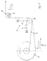
- the device according to the invention includes an unwinding device into which a Winding roll 1 is suspended for unwinding the material web 2.
- a measuring device 3 continuously measures the diameter of the winding roll 1, and a control device determines the fluctuations in diameter from the measured values, caused by out of roundness in the winding roll 1.
- the fluctuations in Diameters of the winding roll 1 lead to changes in length in the running web 2, compensated by the compensation device 4 arranged below become.
- the compensation device 4 arranged behind the unwinding device consists of a roller 5 deflecting the web 2, the position of which with a component in Feed direction of the material web 2 is changeable.
- a change in the position of the Roller 4 leads to a change in length of the railway line, with which there is a change in length the web 2 can compensate.
- the roller 5 is as in the Position changeable deflector mounted on the free end of a lever 6, the extending downward in the direction of the winding roll 1 is pivotally suspended.
- a control device For this purpose, its position is continuously determined and sent to a control device
- a hydraulic piston-cylinder unit is used as the actuator or a position-controlled linear motor is used.
- suspended roller 5 can also be a linearly movable roller or another deflecting element which can be moved linearly or along a curved path be used to change the length of the railway line.
- the load cell 9 detects the amount of tension in the web 2.
- the measurement signal is used to control the speed of the winding roll 1 and thus used for the control of the tension in the web 2.
- the roller 5 is preset to a middle position.
- the control device determines from the measurement signals of the measuring device 3 the fluctuations in the winding roll diameter and controls the actuator 7, the if necessary, the position of the roller 5 changed so that the fluctuations in the Web length can be compensated.
- the compensation system (measuring device 3, Control device, actuator 7, roller 5) is designed so dynamically that fluctuations can be compensated with a frequency of up to 8 Hz.
- FIG. 2 shows an expanded version of a device according to the invention, which an additional compensation device 10 to compensate for short pulsation waves higher frequency does not contain that of the compensation device 4 can be corrected.
- the additional compensation device 10 consists of a deflection tube 11 which a compressed air supply is connected and the pipe wall of the web 2 wrapped area has a plurality of passage openings for the compressed air.
- the web 2 is so contactless on a compressed air cushion 12 floating around the tube 11 steered.
- the height of the air cushion 12 can depend on the performance of the compressed air blower can be varied between 3 mm and 12 mm. Since the air volume under the material web 2 is almost massless, very high-frequency vibrations with small amplitude be compensated very largely.
- the interaction of the position-controlled roller 5 with the air cushion 12 allows fluctuations in the web length over a very to compensate for a wide frequency and amplitude range caused by non-roundness in the Winding roll 1 are caused.
- the pressure of the air cushion 12 is dependent on the tensile stress in the web 2, can the value advantageously as a control variable for controlling the tension in the web 2 be used.
- the pressure in the air cushion 12 is a Probe 13 measured and fed to a pressure / current converter 14. There will be a generates an appropriate electrical signal, which - as described above - for Regulation of the speed of the winding roll 1 and thus to regulate the tension in the Lane 2 is used.
- FIG. 3 shows an embodiment in which the two compensation devices 5, 10 according to FIG. 2 are combined in a single device:
- the position-controlled roller is replaced by an air tube 15 as a deflection device, the Structure corresponds to the air tube 11 according to FIG. 2, and this additionally corresponds to the roller 5 Figure 2 is changeable in its position.
- the web 2 is contactless on one Air cushion 12 guided around the pipe 15 to a subsequent deflecting roller 16 and from this is directed to the processing machine.
- the position of the air tube 15 is on the in the embodiment of Figure 1 described manner depending on the Measuring signal of the measuring device 3 controlled, that is, from the fluctuations in the diameter the winding roll 1.
- the air cushion 12 automatically compensates for high-frequency pulsations with low amplitude. In this embodiment too, the value of Pressure in the air cushion 12 used to control the tension of the web 2, as in the embodiment of Figure 3 described.
Abstract
Description
Die Erfindung betrifft ein Verfahren und eine Vorrichtung zum Zuführen einer von einer
Wickelrolle abgezogenen Materialbahn zu einer Verarbeitungsmaschine gemäß dem
Oberbegriff des Patentanspruchs 1 bzw. des Patentanspruchs 2.The invention relates to a method and an apparatus for feeding one of
Wound roll drawn material web to a processing machine according to the
The preamble of
Um Materialbahnen, beispielsweise Papier- oder Kartonbahnen, Kunststoff- oder Metallfolien, kontinuierlich einer nachfolgenden Verarbeitungsmaschine zuzuführen, werden diese bekannterweise von Wickelrollen abgewickelt, die in eine Abwickelvorrichtung eingehängt sind.To material webs, for example paper or cardboard webs, plastic or Metal foils, continuously fed to a subsequent processing machine, these are known to be unwound from winding rolls, which are in an unwinder are attached.
Sind die Wickelrollen nicht gleichmäßig rund, so führt dies beim Abwickeln zu Längenänderungen in der ablaufenden Materialbahn, die zu Störungen in der nachfolgenden Verarbeitungsmaschine führen können. Aus der DE 37 04 677 sind ein Verfahren und eine Vorrichtung der gattungsgemäßen Art bekannt, bei der die Materialbahn nach dem Abwickeln zum Ausgleich von Längenschwankungen um eine Umlenkeinrichtung geführt wird, die mit einer Komponente in Richtung der zulaufenden Materialbahn bewegbar gelagert ist. Die Umlenkeinrichtung ist eine pendelnd aufgehängte Ausgleichswalze, deren Pendelbewegung von einem Dämpfungszylinder gedämpft wird, dessen Gegenkraft proportional der Bahnspannung ist. Die Materialbahn wird so beruhigt und mit konstanter Spannung der Verarbeitungsmaschine zugeführt.If the winding rolls are not evenly round, this leads to unwinding Changes in length in the running material web, which lead to disturbances in the following Processing machine can lead. DE 37 04 677 describes a method and a device of the generic type known, in which the material web after Unwinding to compensate for length fluctuations performed around a deflection device becomes movable with a component in the direction of the incoming material web is stored. The deflection device is a pendulum-mounted compensating roller, the Pendulum movement is dampened by a damping cylinder, its counterforce is proportional to the web tension. The material web is soothed and with constant Voltage supplied to the processing machine.
Diese bekannte Lösung mit einem Luftzylinder als Dämpfungselement ist nur in der Lage, von Unrundheiten in der Wickelrolle ausgelöste Pulsationen in der Materialbahn mit begrenzten Frequenzen und Amplituden zufriedenstellend auszugleichen. Bei hohen Frequenzen (beispielsweise größer als 3 Hz) und großen Längenänderungen kann die Ausgleichswalze aufgrund ihrer Massenträgheit die erforderlichen Ausgleichsbewegungen nicht ausreichend schnell durchzuführen.This known solution with an air cylinder as a damping element is only able to pulsations in the material web triggered by out-of-roundness in the winding roll to adequately compensate for limited frequencies and amplitudes. At high Frequencies (for example greater than 3 Hz) and large changes in length can Compensating roller due to its inertia the necessary compensating movements not performing quickly enough.
Der Erfindung liegt daher die Aufgabe zugrunde, ein Verfahren und eine Vorrichtung der gattungsgemäßen Art zu schaffen, mit dem (der) auch große Längenänderungen mit hohen Frequenzen ausgeglichen werden können.The invention is therefore based on the object of a method and an apparatus Generic type to create with the (large) changes in length high frequencies can be compensated.
Diese Aufgabe wird mit den Merkmalen des Patentanspruchs 1 bzw. des Patentanspruchs
2 gelöst.This object is achieved with the features of
Nach der Erfindung wird eine die Bahn umlenkende Kompensationseinrichtung eingesetzt, die nicht frei bewegbar, sondern mittels eines gesteuerten oder geregelten Stellantriebs mit einer Komponente in Zulaufrichtung der Materialbahn positionierbar gelagert ist. Eine Meßeinrichtung bestimmt die Schwankungen im Durchmesser der Wickelrolle, und in Abhängigkeit von den gemessenen Werten wird der Stellantrieb von einer Steuereinrichtung so gesteuert oder geregelt, dass die Kompensationseinrichtung jeweils in die erforderliche Position bewegt wird.According to the invention, a compensation device deflecting the web is used, which are not freely movable, but by means of a controlled or regulated actuator is positioned with a component in the feed direction of the material web. A Measuring device determines the fluctuations in the diameter of the winding roll, and in The actuator is dependent on the measured values from a control device controlled or regulated so that the compensation device in each case in the required position is moved.
Die Unteransprüche enthalten bevorzugte, da besonders vorteilhafte Ausgestaltungen der Erfindung.The subclaims contain preferred, since particularly advantageous, configurations of the Invention.
Die Zeichnung dient zur Erläuterung der Erfindung anhand schematisch dargestellter Ausführungsbeispiele:
Figur 1- zeigt die Seitenansicht einer Abwickelvorrichtung mit einer nachfolgenden an einem Hebel aufgehängten Ausgleichswalze mit einem Stellantrieb.
- Figur 2
- zeigt eine Vorrichtung mit einer zusätzlichen Einrichtung zur Kompensation von kurzen Pulsationswellen in der Materialbahn.
Figur 3- zeigt eine Ausführungsform, bei der vorteilhaft sowohl kurze als auch lange Pulsationswellen mit einer einzigen Kompensationseinrichtung ausgeglichen werden.
- Figure 1
- shows the side view of an unwinder with a subsequent compensating roller suspended on a lever with an actuator.
- Figure 2
- shows a device with an additional device for compensating for short pulsation waves in the material web.
- Figure 3
- shows an embodiment in which both short and long pulsation waves are advantageously compensated for with a single compensation device.
Die Vorrichtung gemäß der Erfindung enthält eine Abwickelvorrichtung, in die eine
Wickelrolle 1 zum Abwickeln der Materialbahn 2 eingehängt wird. Eine Meßeinrichtung 3
mißt beim Abwickeln berührungslos kontinuierlich den Durchmesser der Wickelrolle 1, und
eine Steuereinrichtung bestimmt aus den Meßwerten die Schwankungen im Durchmesser,
die durch Unrundheiten in der Wickelrolle 1 verursacht werden. Die Schwankungen im
Durchmesser der Wickelrolle 1 führen zu Längenänderungen in der ablaufenden Bahn 2,
die von der nachfolgend angeordneten Kompensationseinrichtung 4 ausgeglichen
werden.The device according to the invention includes an unwinding device into which a
Die hinter der Abwickelvorrichtung angeordnete Kompensationseinrichtung 4 besteht aus
einer die Bahn 2 umlenkenden Walze 5, deren Position mit einer Komponente in
Zulaufrichtung der Materialbahn 2 veränderbar ist. Eine Veränderung der Position der
Walze 4 führt zu einer Längenänderung der Bahnstrecke, mit der sich eine Längenänderung
der Bahn 2 ausgleichen läßt. Im vorliegenden Beispiel ist die Walze 5 als in der
Position veränderbare Umlenkeinrichtung am freien Ende eines Hebels 6 gelagert, der
sich nach unten erstreckend in Richtung zur Wickelrolle 1 hin schwenkbar aufgehängt ist.
Am Hebel 6 greift ein Stellantrieb 7 an, der von einer Steuereinrichtung gesteuert oder
geregelt die Position der Walze 5 einstellt. Bevorzugt wird die Position des Stellantriebs 7
geregelt. Dazu wird kontinuierlich seine Stellung bestimmt und an eine Regeleinrichtung
gemeldet.Als Stellantrieb wird beispielsweise eine hydraulische Kolben-Zylinder-Einheit
oder ein stellungsgeregelter Linearmotor verwendet. Alternativ zu einer an einem
Schwenkhebel 6 aufgehängten Walze 5 kann auch eine linear verschiebbare Walze oder
ein anderes linear oder entlang einer gekrümmten Bahn bewegbares Umlenkelement
eingesetzt werden, um die Länge der Bahnstrecke zu verändern.The
In Bahnlaufrichtung hinter der Umlenkwalze 5 folgt eine weitere Umlenkwalze 8, die mit
einer Kraftmeßdose 9 verbunden ist. Die Kraftmeßdose 9 erfaßt die Höhe der Zugspannung
in der Bahn 2. Das Meßsignal wird für die Regelung der Drehzahl der Wickelrolle 1
und somit für die Regelung der Zugspannung in der Bahn 2 herangezogen.In the web running direction behind the deflecting
Die in Figur 1 dargestellte Vorrichtung arbeitet wie folgt:The device shown in Figure 1 operates as follows:
Zunächst wird die Walze 5 auf eine Mittellage voreingestellt. Beim Abwickeln mißt die
Meßeinrichtung 3 kontinuierlich berührungslos den Radius der Wickelrolle 1 an der
Bahnablaufstelle. Aus den Meßsignalen der Meßeinrichtung 3 bestimmt die Steuereinrichtung
die Schwankungen im Wickelrollendurchmesser und regelt den Stellantrieb 7, der
erforderlichenfalls die Position der Walze 5 so verändert, dass die Schwankungen in der
Bahnlänge ausgeglichen werden. Das Kompensationssystem (Meßeinrichtung 3,
Steuereinrichtung, Stellantrieb 7, Walze 5) ist so dynamisch ausgelegt, dass Schwankungen
mit einer Frequenz bis zu 8 Hz ausgeglichen werden können.First, the
In Figur 2 ist eine erweiterte Ausführung einer erfindungsgemäßen Vorrichtung dargestellt,
die eine zusätzliche Kompensationseinrichtung 10 zum Ausgleich von kurzen Pulsationswellen
höherer Frequenz enthält, die von der Kompensationseinrichtung 4 nicht
ausgeregelt werden können.FIG. 2 shows an expanded version of a device according to the invention,
which an
Die zusätzliche Kompensationseinrichtung 10 besteht aus einem Umlenkrohr 11, das an
eine Druckluftzufuhr angeschlossen ist und dessen Rohrwand im von der Bahn 2
umschlungenen Bereich eine Vielzahl von Durchtrittsöffnungen für die Druckluft aufweist.
Die Bahn 2 wird so berührungslos auf einem Druckluftpolster 12 schwebend um das Rohr
11 gelenkt. Die Höhe des Luftpolsters 12 kann über die Leistung des Druckluftgebläses
zwischen 3 mm und 12 mm variiert werden. Da das Luftvolumen unter der Materialbahn 2
annähernd masselos ist, können sehr hochfrequente Schwingungen mit kleiner Amplitude
sehr weitgehend kompensiert werden. Das Zusammenwirken der lagegeregelten Walze 5
mit dem Luftpolster 12 ermöglicht es, Schwankungen in der Bahnlänge über einen sehr
weiten Frequenz- und Amplitudenbereich auszugleichen, die durch Unrundheiten in der
Wickelrolle 1 verursacht werden.The
Da der Druck des Luftpolsters 12 von der Zugspannung in der Bahn 2 abhängig ist, kann
der Wert vorteilhaft als Steuergröße zur Steuerung der Zugspannung in der Bahn 2
verwendet werden. Wie in Figur 2 angedeutet, wird der Druck im Luftpolster 12 über eine
Sonde 13 gemessen und einem Druck-/Strom-Wandler 14 zugeführt. Dort wird ein
entsprechendes elektrisches Signal erzeugt, das - wie vorstehend beschrieben - zur
Regelung der Drehzahl der Wickelrolle 1 und somit zur Regelung der Zugspannung in der
Bahn 2 verwendet wird.Since the pressure of the
In Figur 3 ist eine Ausführungsform dargestellt, bei der die beiden Kompensationseinrichtungen
5, 10 nach Figur 2 in einer einzigen Einrichtung zusammengefaßt sind: FIG. 3 shows an embodiment in which the two
Die lagegesteuerte Walze ist durch ein Luftrohr 15 als Umlenkeinrichtung ersetzt, dessen
Aufbau dem Luftrohr 11 nach Figur 2 entspricht und das zusätzlich wie die Walze 5 nach
Figur 2 in seiner Position veränderbar ist. Die Bahn 2 wird berührungslos auf einem
Luftpolster 12 um das Rohr 15 zu einer nachfolgenden Umlenkwalze 16 geführt und von
dieser zu der Verarbeitungsmaschine geleitet. Die Position des Luftrohrs 15 wird auf die
bei der Ausführungsform nach Figur 1 beschriebene Weise in Abhängigkeit von dem
Meßsignal der Meßeinrichtung 3 gesteuert, also von den Schwankungen im Durchmesser
der Wickelrolle 1. Das Luftpolster 12 kompensiert automatisch hochfrequente Pulsationen
mit geringer Amplitude. Auch bei dieser Ausführungsform wird vorteilhaft der Wert des
Drucks im Luftpolster 12 zur Steuerung der Zugspannung der Bahn 2 verwendet, wie bei
der Ausführungsform nach Figur 3 beschrieben.The position-controlled roller is replaced by an
Claims (6)
Die Umlenkeinrichtung (5, 15) ist mittels eines gesteuerten oder geregelten Stellantriebs (7) positionierbar gelagert,
The deflection device (5, 15) is positioned so that it can be positioned by means of a controlled or regulated actuator (7),
Applications Claiming Priority (2)
| Application Number | Priority Date | Filing Date | Title |
|---|---|---|---|
| DE19900536 | 1999-01-11 | ||
| DE19900536A DE19900536A1 (en) | 1999-01-11 | 1999-01-11 | Method and device for feeding a web of material drawn from a winding roll to a processing machine |
Publications (2)
| Publication Number | Publication Date |
|---|---|
| EP1020391A1 true EP1020391A1 (en) | 2000-07-19 |
| EP1020391B1 EP1020391B1 (en) | 2003-05-02 |
Family
ID=7893830
Family Applications (1)
| Application Number | Title | Priority Date | Filing Date |
|---|---|---|---|
| EP99124513A Expired - Lifetime EP1020391B1 (en) | 1999-01-11 | 1999-12-09 | Unit for and method of feeding a web unwound from a winding roll to a processing machine |
Country Status (2)
| Country | Link |
|---|---|
| EP (1) | EP1020391B1 (en) |
| DE (2) | DE19900536A1 (en) |
Cited By (1)
| Publication number | Priority date | Publication date | Assignee | Title |
|---|---|---|---|---|
| FR2849649A1 (en) * | 2003-01-08 | 2004-07-09 | Komori Chambon | Shaping apparatus with interchangeable plates |
Citations (5)
| Publication number | Priority date | Publication date | Assignee | Title |
|---|---|---|---|---|
| US4657198A (en) * | 1984-05-18 | 1987-04-14 | Fuji Photo Film Co., Ltd. | Apparatus for measuring the thickness of a roll winding on or unwinding from a core |
| DE3704677A1 (en) * | 1986-12-27 | 1988-07-07 | Kampf Gmbh & Co Maschf | Process and device for the edge-regulated introduction of a material web into a processing machine |
| DE4425355A1 (en) * | 1993-07-16 | 1995-01-26 | Siemens Ag | Regulation for the drive of a winder (coiler) |
| DE19614300A1 (en) * | 1995-04-21 | 1996-10-24 | Abb Patent Gmbh | Automatic compensation of out of round roller rotation, esp. for winding webs of paper or plastics film |
| US5659229A (en) * | 1995-01-31 | 1997-08-19 | Kimberly-Clark Worldwide, Inc. | Controlling web tension by actively controlling velocity of dancer roll |
-
1999
- 1999-01-11 DE DE19900536A patent/DE19900536A1/en not_active Withdrawn
- 1999-12-09 DE DE59905311T patent/DE59905311D1/en not_active Expired - Fee Related
- 1999-12-09 EP EP99124513A patent/EP1020391B1/en not_active Expired - Lifetime
Patent Citations (5)
| Publication number | Priority date | Publication date | Assignee | Title |
|---|---|---|---|---|
| US4657198A (en) * | 1984-05-18 | 1987-04-14 | Fuji Photo Film Co., Ltd. | Apparatus for measuring the thickness of a roll winding on or unwinding from a core |
| DE3704677A1 (en) * | 1986-12-27 | 1988-07-07 | Kampf Gmbh & Co Maschf | Process and device for the edge-regulated introduction of a material web into a processing machine |
| DE4425355A1 (en) * | 1993-07-16 | 1995-01-26 | Siemens Ag | Regulation for the drive of a winder (coiler) |
| US5659229A (en) * | 1995-01-31 | 1997-08-19 | Kimberly-Clark Worldwide, Inc. | Controlling web tension by actively controlling velocity of dancer roll |
| DE19614300A1 (en) * | 1995-04-21 | 1996-10-24 | Abb Patent Gmbh | Automatic compensation of out of round roller rotation, esp. for winding webs of paper or plastics film |
Cited By (1)
| Publication number | Priority date | Publication date | Assignee | Title |
|---|---|---|---|---|
| FR2849649A1 (en) * | 2003-01-08 | 2004-07-09 | Komori Chambon | Shaping apparatus with interchangeable plates |
Also Published As
| Publication number | Publication date |
|---|---|
| DE19900536A1 (en) | 2000-07-13 |
| EP1020391B1 (en) | 2003-05-02 |
| DE59905311D1 (en) | 2003-06-05 |
Similar Documents
| Publication | Publication Date | Title |
|---|---|---|
| DE3539980C2 (en) | Method and device for controlling a paper web rewinder | |
| DE3214396C2 (en) | Device for winding up a web, such as a paper web | |
| DE3114056C2 (en) | ||
| DE3812449C2 (en) | Method and device for regulating the thread tension in a winding unit of an automatic winder | |
| EP0026335A1 (en) | Control device on apparatuses for winding webs of material on rolls and method of winding pressure-sensitive webs of material on rolls | |
| AT506493B1 (en) | METHOD FOR ROLLING A PAPER OR CARDBOARD, AND ROLLING DEVICE | |
| DE3639244A1 (en) | ROLLING DEVICE FOR MOVING RAILWAYS | |
| EP0289776B1 (en) | Device for winding and unwinding a web | |
| WO1991016257A1 (en) | Process and device for winding continuous webs of material, in particular paper or carton | |
| DE3805950A1 (en) | DISCONNECTING AND REWINDING DEVICE FOR RAILWAYS | |
| EP0792714A1 (en) | Wire electrode feeding arrangement for electric discharge machining apparatus | |
| EP1484443B1 (en) | Device and method for controlling the tension force of a moving web | |
| DE10250863B4 (en) | Winding device for web-shaped materials, in particular plastic films | |
| EP0988121A1 (en) | Unwinding adjustment device for wire or materials containing several wires | |
| DE4131760C2 (en) | Method and device for regulating the tension of a textile web | |
| DE3426976A1 (en) | DEVICE FOR CARRYING OUT A ROLE CHANGE | |
| EP1020391B1 (en) | Unit for and method of feeding a web unwound from a winding roll to a processing machine | |
| WO2013029734A1 (en) | 2‑drum winder | |
| EP1826002B1 (en) | Printing press with web tension control | |
| DE19524729A1 (en) | Method and device for rolling strips with a non-uniform thickness and / or length distribution across their width | |
| EP0158199A1 (en) | Yarn-sensing device | |
| EP0625473A2 (en) | Method and device for uniforming the winding density of a winding profile of a film roll | |
| EP2565136A1 (en) | Method for coiling cut transported coil windings and two-drum winder | |
| DE10310399A1 (en) | Device and method for rolling metal strips | |
| DE19946400B4 (en) | Method for winding a material web |
Legal Events
| Date | Code | Title | Description |
|---|---|---|---|
| PUAI | Public reference made under article 153(3) epc to a published international application that has entered the european phase |
Free format text: ORIGINAL CODE: 0009012 |
|
| AK | Designated contracting states |
Kind code of ref document: A1 Designated state(s): DE ES FI FR GB IT |
|
| AX | Request for extension of the european patent |
Free format text: AL;LT;LV;MK;RO;SI |
|
| 17P | Request for examination filed |
Effective date: 20000809 |
|
| AKX | Designation fees paid |
Free format text: DE ES FI FR GB IT |
|
| GRAH | Despatch of communication of intention to grant a patent |
Free format text: ORIGINAL CODE: EPIDOS IGRA |
|
| GRAH | Despatch of communication of intention to grant a patent |
Free format text: ORIGINAL CODE: EPIDOS IGRA |
|
| GRAA | (expected) grant |
Free format text: ORIGINAL CODE: 0009210 |
|
| AK | Designated contracting states |
Designated state(s): DE ES FI FR GB IT |
|
| PG25 | Lapsed in a contracting state [announced via postgrant information from national office to epo] |
Ref country code: FR Free format text: LAPSE BECAUSE OF FAILURE TO SUBMIT A TRANSLATION OF THE DESCRIPTION OR TO PAY THE FEE WITHIN THE PRESCRIBED TIME-LIMIT Effective date: 20030502 Ref country code: FI Free format text: LAPSE BECAUSE OF FAILURE TO SUBMIT A TRANSLATION OF THE DESCRIPTION OR TO PAY THE FEE WITHIN THE PRESCRIBED TIME-LIMIT Effective date: 20030502 |
|
| REG | Reference to a national code |
Ref country code: GB Ref legal event code: FG4D Free format text: NOT ENGLISH |
|
| GBT | Gb: translation of ep patent filed (gb section 77(6)(a)/1977) |
Effective date: 20030502 |
|
| REF | Corresponds to: |
Ref document number: 59905311 Country of ref document: DE Date of ref document: 20030605 Kind code of ref document: P |
|
| PG25 | Lapsed in a contracting state [announced via postgrant information from national office to epo] |
Ref country code: ES Free format text: LAPSE BECAUSE OF FAILURE TO SUBMIT A TRANSLATION OF THE DESCRIPTION OR TO PAY THE FEE WITHIN THE PRESCRIBED TIME-LIMIT Effective date: 20030813 |
|
| PLBE | No opposition filed within time limit |
Free format text: ORIGINAL CODE: 0009261 |
|
| STAA | Information on the status of an ep patent application or granted ep patent |
Free format text: STATUS: NO OPPOSITION FILED WITHIN TIME LIMIT |
|
| 26N | No opposition filed |
Effective date: 20040203 |
|
| EN | Fr: translation not filed | ||
| PGFP | Annual fee paid to national office [announced via postgrant information from national office to epo] |
Ref country code: DE Payment date: 20051212 Year of fee payment: 7 |
|
| PGFP | Annual fee paid to national office [announced via postgrant information from national office to epo] |
Ref country code: GB Payment date: 20051222 Year of fee payment: 7 |
|
| PG25 | Lapsed in a contracting state [announced via postgrant information from national office to epo] |
Ref country code: DE Free format text: LAPSE BECAUSE OF NON-PAYMENT OF DUE FEES Effective date: 20070703 |
|
| GBPC | Gb: european patent ceased through non-payment of renewal fee |
Effective date: 20061209 |
|
| PG25 | Lapsed in a contracting state [announced via postgrant information from national office to epo] |
Ref country code: GB Free format text: LAPSE BECAUSE OF NON-PAYMENT OF DUE FEES Effective date: 20061209 |
|
| PGFP | Annual fee paid to national office [announced via postgrant information from national office to epo] |
Ref country code: IT Payment date: 20171221 Year of fee payment: 19 |
|
| PG25 | Lapsed in a contracting state [announced via postgrant information from national office to epo] |
Ref country code: IT Free format text: LAPSE BECAUSE OF NON-PAYMENT OF DUE FEES Effective date: 20181209 |